


Statement:
This manual is the intellectual property of Foxconn, Inc. Although the information in this manual may be changed or modified at any time, Foxconn does not obligate itself to inform the user of these changes.
Trademark:
All trademarks are the property of their respective owners.
Version:
User’s Manual V1.2 for N570SM2AA motherboard.
P/N: 3A220BA00-000-G
Symbol description:
 Note: refers to important information that can help you to use motherboard better.
 Attention: indicates that it may damage hardware or cause data loss, and tells you how to avoid such problems.
 Warning: means that a potential risk of property damage or physical injury exists.
More information:
If you want more information about our products, please visit Foxconn’s website: http://www.foxconnchannel.com
This product and its accessories are produced after 13th Aug., 2005 and comply with the WEEE2002/96EC directive.

Declaration of conformity
HON HAI PRECISION INDUSTRY COMPANY LTD
66 , CHUNG SHAN RD., TU-CHENG INDUSTRIAL DISTRICT,
TAIPEI HSIEN, TAIWAN, R.O.C.
declares that the product
Motherboard
N570SM2AA
is in conformity with
(reference to the specification under which conformity is declared in accordance with 89/336 EEC-EMC Directive)
þ EN |
55022: 1998/A2: 2003 |
Limits and methods of measurements of radio disturbance |
||||
þ EN |
|
|
characteristics of information technology equipment |
|||
61000-3-2/:2000 |
Electromagnetic compatibility (EMC) |
|||||
|
|
|
Part 3: Limits |
|||
|
|
|
Section 2: Limits for harmonic current emissions |
|||
þ EN |
|
|
(equipment input current <= 16A per phase) |
|||
61000-3-3/A1:2001 |
Electromagnetic compatibility (EMC) |
|||||
|
|
|
Part 3: Limits |
|||
|
|
|
Section 2: Limits of voltage fluctuations and flicker in low-voltage |
|||
þ EN |
|
|
supply systems for equipment with rated current <= 16A |
|||
55024/A2:2003 |
Information technology equipment-Immunity characteristics limits |
|||||
|
|
|
and methods of measurement |
|||
Signature : |
|
|
Place / Date : TAIPEI/2007 |
|||
|
|
|
|
|
|
|
Printed Name : James Liang |
Position/ Title : Assistant President |
|
|
|
|

Declaration of conformity
Trade Name: |
WinFast |
Model Name: |
N570SM2AA |
Responsible Party: |
PCE Industry Inc. |
Address: |
458 E. Lambert Rd. |
|
Fullerton, CA 92835 |
Telephone: |
714-738-8868 |
Facsimile: |
714-738-8838 |
Equipment Classification: |
FCC Class B Subassembly |
Type of Product: |
Motherboard |
Manufacturer: |
HON HAI PRECISION INDUSTRY |
|
COMPANY LTD |
Address: |
66 , CHUNG SHAN RD., TU-CHENG |
|
INDUSTRIAL DISTRICT, TAIPEI HSIEN, |
|
TAIWAN, R.O.C. |
SupplementaryInformation: |
|
This device complies with Part 15 of the FCC Rules. Operation is subject to the following two conditions : (1) this device may not cause harmful interference, and (2) this device must accept any interference received, including interference that may cause undesired operation.
Tested to comply with FCC standards.
Signature : |
Date : 2007 |

|
|
Table of Contents |
|
Chapter |
1 |
Product Introduction |
|
Main Features ......................................................................................... |
|
2 |
|
Layout ....................................................................................................... |
|
|
4 |
Rear Panel Ports |
.................................................................................... |
5 |
|
Chapter |
2 |
Installation Instructions |
|
CPU .......................................................................................................... |
|
|
8 |
Memory................................................................................................... |
|
|
11 |
Power Supply ....................................................................................... |
|
13 |
|
Other Connectors |
................................................................................ |
14 |
|
Expansion Slots ................................................................................... |
|
18 |
|
Jumpers ............................................................................................... |
|
|
19 |
Chapter |
3 |
BIOS Description |
|
Enter BIOS Setup |
................................................................................. |
21 |
|
Main menu ............................................................................................ |
|
|
21 |
Standard CMOS Features ................................................................... |
23 |
||
Tiger Central Control Unit ...................................................................... |
25 |
||
Advanced BIOS Features .................................................................... |
28 |
||
Advanced Chipset Features ............................................................... |
31 |
||
Integrated Peripherals ........................................................................ |
32 |
||
Power Management Setup ................................................................. |
37 |
||
PnP/PCI Configurations ...................................................................... |
40 |
||
PC Health Status |
................................................................................. |
41 |
|
Load Fail-Safe Defaults ..................................................................... |
42 |
||
Load Optimized |
Defaults .................................................................. |
42 |
|
Set Supervisor/User Password ......................................................... |
42 |
||
Save & Exit Setup |
................................................................................. |
43 |
|
Exit Without Saving .............................................................................. |
43 |
||

|
|
Table of Contents |
|
Chapter |
4 |
Driver CD Introduction |
|
Utility CD content |
................................................................................. |
45 |
|
Installing drivers .................................................................................. |
|
46 |
|
Installing Utilities |
................................................................................. |
46 |
|
Chapter |
5 |
Directions for Bundled Software |
|
TIGER ONE ............................................................................................. |
|
48 |
|
Fox LiveUpdate .............................................................................. |
...... |
55 |
|
|
|
Appendix |
|
NVIDIA SLITM Technology .................................................................... |
62 |
||
NVIDIA RAID......................................................................................... |
|
65 |
|
Audio Configuration ............................................................................. |
77 |
||

 Attention:
1.Attach the CPU and heatsink using silica gel to ensure full contact.
2.It is suggested to select high-quality, certified fans in order to avoid damage to the motherboard and CPU due high temperatures.
3.Never turn on the machine if the CPU fan is not properly installed.
4.Ensure that the DC power supply is turned off before inserting or removing expansion cards or other peripherals, especially when you insert or remove a memory module. Failure to switch off the DC power supply may result in serious damage to your system or memory module.
 Attention:
We cannot guarantee that your system will operate normally while over-clocked. Normal operation depends on the over-clock capacity of your device.
 Attention:
Since BIOS programs are upgraded from time to time, the BIOS description in this manual is just for reference. We do not guarantee that the content of this manual will remain consistent with the actual BIOS version at any given time in the future.
 Attention:
The pictures of objects used in this manual are just for your reference. Please refer to the physical motherboard.

This manual is suitable for motherboard of N570SM2AA. Each motherboard is carefully designed for the PC user who wants diverse features.
-6 with 6-Channel audio (Default iomitted.) -8 with 8-Channel audio
-E with 1394 function
-L with onboard 10/100M LAN (Default is omitted.) -K with onboard Gigabit LAN
-R with RAID function -S with SATA function -2 with DDR2 slots
-H comply with RoHS directive
You can find PPID label on the motherboard. It indicates the functions that the motherboard has.
For example:
The latters on the black mark of the PPID label mean that the motherboard supports 6-channel Audio (-6, Default is omitted), onboard 10/100M LAN (-L, Default is omitted), 1394 function (- E), SATA function (-S), DDR2 Slots(-2), RoHS Directive(-H).

Chapter1
Thank you for buying FOXCONN N570SM2AA series motherboard. This series of motherboard is one of our new products, offers superior performance, and uses the advanced NVIDIA nForce® 570 SLI MCP.
This chapter includes the following information:
vMain Features
vLayout
vRear I/O Ports

Chapter 1 Product Introduction
Main Features
Size
·ATX form factor of 12 inch x 9.6 inch
Microprocessor
·Supports AMD® Socket AM2 AthlonTM 64 X2 Dual-Core, AthlonTM 64 FX, AthlonTM 64 and SempronTM processors
·Supports HyperTransportTM up to 2000MT/s
MCP
· NVIDIA nForce® 570 SLI MCP
System Memory
·Four 240-pin DIMM slots
·Supports Dual-Channel DDR2 533/667/800
·Supports up to 8GB DDR2 memory
USB 2.0 Ports
·Supports hot plug
·Ten USB 2.0 ports (four rear panel ports, three onboard USB headers providing six extra ports)
·Supports wake-up from S1 and S3 mode
·Supports USB 2.0 protocol up to 480Mb/s transmission rate
Onboard Serial ATA II
·300MB/s data transfer rate
·Seven Serial ATA II and one E-SATA1 connectors
·NVIDIA MediaShieldTM RAID with support for RAID 0, RAID 1, RAID 0+1, RAID 5
Dual Onboard LAN (-K)
·Two LAN interface built-in onboard
·Supports 10/100/1000(-K)Mb/s Ethernet
 2
2 

Chapter 1 Product Introduction
Onboard 1394 (-E ) (optional)
·Supports hot plug
·Two 1394a ports with rate of transmission at 400Mb/s
Onboard Audio (-8)
·Supports 8-channel audio
·Supports S/PDIF output
·Supports Jack-Sensing function
Dual PCI Express x16
·Slot PCI-E1_X16 supports PCI Express X16 ·Supports 4 GB/s bandwidth
·Slot PCI-E2_X16 supports PCI Express X8 ·Supports 2 GB/s bandwidth
· Low power consumption and power management features
Green Function
·Supports ACPI (Advanced Configuration and Power Interface)
·Supports S0 (normal), S1 (power on suspend), S3 (suspend to RAM), S4 (Suspend to disk - depends on OS), and S5 (soft - off)
·Supports AMD® Cool ‘n’ QuietTM technology
Expansion Slots
·Two PCI slots
·Two PCI Express x1 slots
·Two PCI Express x16 Graphics slots
 3
3
Chapter 1 Product Introduction
Layout
27 |
26 |
25 |
24 |
23 22 |
21 |
1 
 20
20
2 
 19
19
18
3
|
|
|
|
|
17 |
4 |
|
|
|
|
|
|
|
|
|
|
16 |
5 |
|
|
|
|
15 |
6 |
|
|
|
|
|
7 |
|
|
|
|
14 |
8 |
9 |
10 |
11 |
12 |
13 |
1.CD_IN Connector 2.Front Audio Connector 3.Speaker Connector
4.Front 1394 Connector(optional) 5.SYS_ FAN Connector
6.Front USB Connectors 7.Front Panel Connector 8.Chassis Intruder Connector 9.Clear CMOS Jumper 10.Serial ATA II Connectors 11.FAN Connector
12.ATA 133/100/66 IDE Connectors 13.FDD Connector
14.24-pin ATX Power Connector
 Note: The above motherboard layout is provided for reference only, please refer to the physical motherboard.
 4
4 

Chapter 1 Product Introduction
Rear I/O Ports
This motherboard provides the ports as below:
10 |
9 |
1
 8
8
2
3 |
4 |
5 |
6 |
7 |
1. PS/2 Mouse Port
This port is used to connect a PS/2 mouse.
2. PS/2 Keyboard Port
This port is used to connect a PS/2 keyboard.
3. External SATA Port
This port is used to connect an external SATA box or a Serial ATA port multiplier and enables smart setup and hot-plug function.
4. Coaxial S/PDIF Out Port
This port is used to connect an external audio output device via a coaxial S/P- DIF cable.
5. Optical S/PDIF Out Port
This port is used to connect an external audio output device via a optical S/P- DIF cable.
6. 1394a Port(optional)
This port is used to connect a 1394 device.
7. USB 2.0 Ports
The four ports are used to connect USB 2.0/1.1 devices.
 5
5

Chapter 1 Product Introduction
8. Line in, Line out, Microphone, Rear, LEF/CEN, Side Jacks
Port |
2-channel |
|
4-channel |
|
6-channel |
8-channel |
||
Blue |
Line In |
|
Line In |
|
Line In |
Line In |
|
|
Green |
Line Out |
Front Speaker Out |
Front Speaker Out |
Front Speaker Out |
||||
Pink |
Mic In |
|
Mic In |
|
Mic In |
Mic In |
|
|
Orange |
- |
- |
|
|
Center/Subwoofer |
Center/Subwoofer |
||
Black |
- |
Rear Speaker Out |
Rear Speaker Out |
Rear Speaker Out |
||||
Grey |
- |
- |
|
|
- |
Side Speaker Out |
||
9. LAN Ports |
|
|
|
|
|
|
|
|
Left : Link/Active LED |
|
Right: Speed LED |
Link/Active |
Speed |
||||
Status |
Description |
|
Status |
|
Description |
LED |
LED |
|
|
|
|
|
|||||
Off |
No Link |
|
Off |
|
10 Mbps Connection |
|
|
|
Green |
Linked |
|
Green |
|
100 Mbps Connection |
LAN Port |
||
Blinking |
Data Activity |
|
Orange |
|
1 Gbps Connection |
|||
|
|
|
|
|||||
|
|
|
|
|
|
|
|
|
10. Parallel Port
The port is used to connect a parallel port device, such as a printer.
 6
6 
Chapter 1 Product Introduction
Chapter2
This chapter introduces the hardware installation process, including the installation of the CPU, memory, power supply, slots, and pin headers, and the mounting of jumpers. Caution should be exercised during the installation of these modules. Please refer to the motherboard layout prior to
any installation and read the contents in this chapter carefully.
This chapter includes the following information:
vCPU
vMemory
vPower supply
vOther Connectors
vExpansion Slots
vJumpers
 7
7
Chapter 2 Installation Instructions
CPU
This motherboard supports AMD Socket AM2 AthlonTM 64 X2 Dual-Core, AthlonTM 64 FX, AthlonTM 64 and SempronTM processors with HyperTransportTM Technology.
 Attention:
The CPU pins must be properly aligned with the holes in the socket, otherwise the CPU may be damaged.
For the detailed CPU vendor list qualified on this motherboard, please visit the website: http://www.foxconnchannel.com
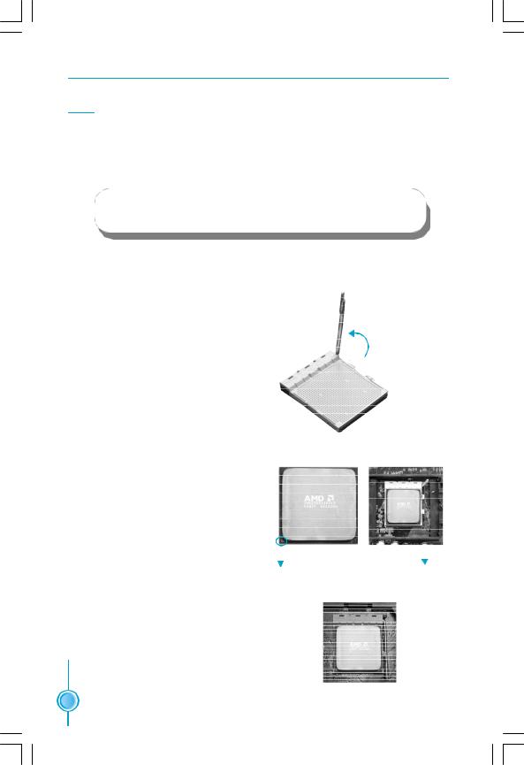
Installation of CPU
Follow these steps to install the CPU.
90o
1. Unlock the socket by pressing the lever sideways, then lift it up to a 90o angle.

 Gap in the base
2.Align the cut edge to the gap in the base of the socket. Carefully insert the CPU into the socket until it fits in place.
Cut edge
3.When the CPU is in place, press it firmly on the socket while you push down the socket lever to secure the CPU. The lever clicks on the side tab to indicate that it is locked.
Push down the socket lever to secure the CPU.
 8
8 

Chapter 2 Installation Instructions
Installation of CPU Fan
New technology allows processors to run at higher and higher frequencies. To avoid problems arising from high-speed operation, for example, overheating, you need to install the proper fan. The following procedure is provided for reference only, please refer to your CPU fan user guide for the actual procedure.
CPU Fan 
CPU Heatsink
CPU Retention |
|
Mechanism |
|
CPU Retention Bracket |
|
|
CPU Retention Lock |
1.Locate the CPU retention mecha- |
2.If required, apply a light coating of |
nism base (surrounds the CPU |
silica gel to the top of the CPU. |
socket). |
|
NOTE: The CPU heatsink may have a pre-applied thermal compound. In that case, the silica gel is not required.
 9
9

Chapter 2 Installation Instructions
3. Place the cooling set onto the retention mechanism. Attach one end of the retention bracket to retention mechanism.
5.Push down the retention bracket lock on the retention mechanism to secure the heatsink and fan to module base.
4.Align the other end of the retention bracket to fasten the cooling set on the top of the retention mechanism.
6.Connect the fan’s power cable to the appropriate 4-pin terminal on the motherboard.
 10
10 

Chapter 2 Installation Instructions
Memory
This motherboard includes four 240-pin slots with 1.8V for DDR2. These slots support 256 Mb, 512 Mb and 1 Gb DDR2 technologies for x8 and x16 devices, and support dual channel DDR2 memory technology up to 10.7GB/s. You must install at least one memory bank to ensure normal operation.
Recommended Memory Configurations
The following table list is the recommended memory configurations. Please install the memory according to the list.
Mode |
DIMM1 |
DIMM2 |
DIMM3 |
DIMM4 |
|
Populated |
|
|
|
|
|
Populated |
|
|
|
|
|
Populated |
|
Single Channel |
|
|
|
Populated |
Populated |
|
Populated |
|
|
|
|
|
||
|
|
Populated |
|
Populated |
|
Populated |
|
|
Populated |
|
|
Populated |
Populated |
|
|
Populated |
Populated |
|
|
Dual Channel |
|
|
Populated |
Populated |
|
Populated |
Populated |
Populated |
Populated |
Installation of DDR2 Memory
1.There is only one gap near the center of the DIMM slot, and the memory module can be fixed in one direction only. Unlock a DIMM slot by pressing the module clips outward.
2.Align the memory module to the DIMM slot, and insert the module vertically into the DIMM slot.
128 Pins |
112 Pins |
3. The plastic clips at both sides of the DIMM slot will lock automatically.
 11
11 

Chapter 2 Installation Instructions
 Warning :
Be sure to unplug the AC power supply before adding or removing expansion cards or other system peripherals, especially the memory devices, otherwise your motherboard or the system memory might be seriously damaged.
For the detailed memory support list on this motherboard, please visit the website: http://www.foxconnchannel.com
 12
12 
Chapter 2 Installation Instructions
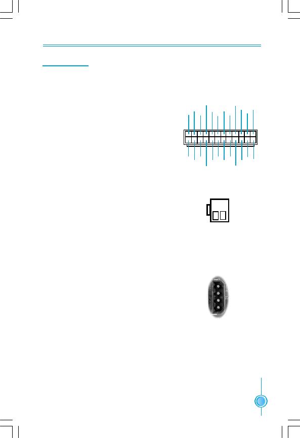
Power Supply
This motherboard uses an ATX power supply. In order to avoid damaging any devices, make sure that they have been installed properly prior to connecting the power supply.
24-pin ATX power connector: PWR1
PWR1 is the ATX power supply connector. Make sure that the power supply cable and pins are properly aligned with the connector on the motherboard. Firmly plug the power supply cable into the connector and make sure it is secure.
|
+5V |
|
+5V_AUX |
+3.3V |
|||
+3.3V |
GND |
GND |
|
+12V |
|||
|
+12V |
||||||
+ 3. 3 V |
GND |
+5V PWROK |
|||||
|
|
||||||
1 |
|
|
|
|
|
12 |
|
13 |
|
|
|
|
|
24 |
|
+3.3V |
GND |
GND |
NC |
+5V |
|||
-12V |
GND |
GND |
|
+5V |
GND |
||
|
PSON |
|
+5V |
|
|||
4-pin ATX_12 V Power Connector: PWR2
The 4-pin ATX 12V power supply connects to PWR2 and provides power to the CPU.
PWR1
3 1
12V
 GND
GND
12V
 GND
GND
4 2
PWR2
Exclusive Graphics Power Connector: PWR3
This connector is a auxiliary power for graphics card. Exclusive power for graphics card is for better graphics performance and for future upgrade usage.
Exclusive Graphics Power Connector
4 + 5 V
+ 5 V
 GN D
GN D
 GN D
GN D
 +1 2V
+1 2V
1
 13
13 
Chapter 2 Installation Instructions
Other Connectors
This motherboard includes connectors for FDD device, IDE devices, Serial ATA devices, USB devices and others.
FDD Connector: FLOPPY
This motherboard includes a standard FDD connector, supporting 360K, 720K, 1.2M, 1.44M, and 2.88M FDDs.
IDE Connector: PIDE & SIDE
The IDE connector supports Ultra ATA 133/100/66 IDE hard disk drives. Connect the cable’s blue connector to the IDE connector, then connect the gray connector to the slave device (hard disk drive) and the black connector to the Ultra ATA master device. If you install two hard disks, you must configure the second drive as a slave device by setting its jumper accordingly. Refer to the hard disk documentation for the jumper settings.
 Attention:
Ribbon cables are directional, therefore, make sure to always connect with the cable on the same side as pin 1 of the PIDE or FLOPPY connector on the motherboard.
 14
14 

Chapter 2 Installation Instructions
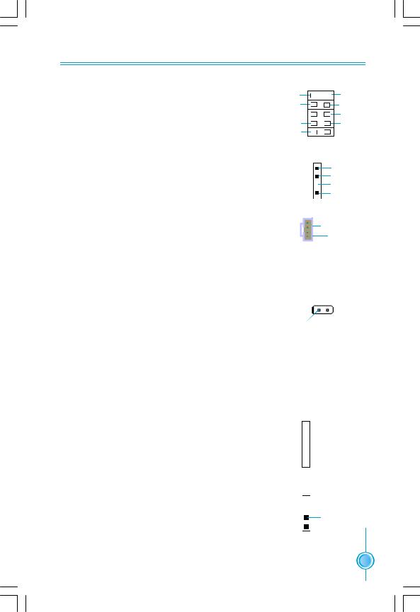
Front Panel Connector: FP1
This motherboard includes one connector for connecting the front panel switch and LED indicators.
|
PWRSW |
|
PWRLED |
Empty |
|
+ |
- |
|
2 |
|
10 |
1 |
|
9 |
+ |
- |
|
HDD-LED |
|
|
|
RESET NC |
|
FP1
HDD LED Connector (HDD-LED)
The connector connects to the case’s HDD indicator LED indicating the activity status of hard disks.
Reset Switch (RESET)
Attach the connector to the Reset switch on the front panel of the case; the system will restart when the switch is pressed.
Power LED Connector (PWRLED)
Attach the connector to the power LED on the front panel of the case. The Power LED indicates the system’s status. When the system is in S0 status, the LED is on. When the system is in S1, S3, S4, S5 status, the LED is off.
Power Switch Connector (PWRSW)
Attach the connector to the power button of the case. Pushing this switch allows the system to be turned on and off rather than using the power supply button.
Audio Connector: F_AUDIO_1
The audio connector supports HD audio standard. It provides two kinds of audio output choices: the Front Audio, the Rear Audio. Front Audio supports re-tasking function.
1 |
2 |
PORT1_L |
AUD_GND |
PORT1_R |
PRESENCE_J |
PORT2_R |
SENSE1_RETURN |
SENSE_SEND |
Empty |
PORT2_L |
SENSE2_RETURN |
9 |
10 |
F_AUDIO_1
 15
15 

Chapter 2 Installation Instructions
Serial ATA II Connectors: SATA_1, SATA_2, SATA_3, SATA_4, SATA_5, SATA_6,
The Serial ATA II connectors are used to connect the Serial ATA II devices to the motherboard. These connectors support the thin Serial ATA II cables for primary storage devices. The current Serial ATA II interface allows up to 300MB/s data transfer rate.
The serial ATA II connectors support RAID 0, RAID 1, RAID 0+1, RAID 5 Function.
RX+GND RX-
RX-
TX- GND
TX+GND 1
1
SATA _1/2/3/4/5/6
Fan Connectors: CPU_FAN, SYS_FAN, FAN
The fan speed can be detected and viewed in “PC Health Status” section of the CMOS Setup. These fans will be automatically turned off after the system enters S3, S4 and S5 mode.
USB Headers: F_USB1, F_USB2, F_USB3
Besides four USB ports on the rear panel, the series of motherboards also have three 10-pin headers on board which may connect to front panel USB cable to provide additional six USB ports.
GND +12V SENSE
|
SYS-FAN |
1 |
FAN |
GND SENSE |
|
1 |
CPU_FAN |
POWER CONTROL |
|
10 |
9 |
NC |
Empty |
GND
 GND
GND
D+
 D+
D+
D- 
 D-
D-
5V_DUAL
 5V_DUAL
2 1
F_USB 1/2/3
Additional COM Connector: COM1
This motherboard provides an additional COM header for your machine.
Connect one side of a switching cable to the header, then attach the COM device to the other side of the cable.
DTR# CTS#
SIN DSR# |
Empty |
2 |
10 |
1 |
9 |
RLSD GND RI#
SOUT RTS#
COM1
 16
16 
Chapter 2 Installation Instructions
IEEE 1394a Connector: F_1394_1 (optional)
The 1394 expansion cable can be connected to either the front (provided that the front panel of your chassis is equipped with the appropriate interface) or real panel of the chassis.
Speaker Connector: SPEAKER
The speaker connector is used to connect speaker of the chassis.
Audio Connectors: CD_IN
CD_IN is Sony standard CD audio connectors, it can be connected to a CD-ROM drive through a CD audio cable.
10 |
9 |
GND |
Empty |
+12V |
+12V |
TPB - |
TPB + |
GND |
GND |
TPA - |
TPA + |
2 |
1 |
F_1394_1 |
|
|
SPKJ |
|
NC |
|
Empty |
1 |
+5V |
SPEAKER
1 CD_L
CD_L
 GND
GND
CD_R
CD_IN
Chassis Intruder Connector: INTR
The connector connects to the chassis security switch on the case.The system can detect the chassis intrusion through the status of this connector. If the connector has been closed once, the system will send a message. To utilize this function, set “Case Open Warning” to “Enabled” in the “Power Management Setup” section of the CMOS Setup. Save and exit, then boot the operating system once to make sure this function takes effect.
1 INTRUDERJ 2 GND
INTR
IrDA Connector: IR
This header supports wireless transmitting and receiving device. Before using this function, configure the s- ettings of IR Mode from the “Integrated Peripherals” s- ection of the CMOS Setup.
S/PDIF-OUT Connector: SPDIF _OUT
The SPDIF OUT Connector is capable of providing digital audio to external speakers or compressed AC3 data to an external Dolby digital decoder.

 IRTX
IRTX

 GND
GND

 IRRX
IRRX
 Key 1
Key 1 
 +5V
+5V
IR
1  +5V
+5V
 Empty
Empty
1 SPDIF_OUT
 GND
GND
SPDIF_OUT
 17
17 

Chapter 2 Installation Instructions
Expansion Slots
This motherboard includes two 32-bit master PCI bus slots, two PCI Express x1 slots, and two PCI Express x16 slots.
PCI Slots
The expansion cards can be installed in the two PCI slots. PCI slots support cards such as a LAN card, USB card, SCSI card and other cards that comply with PCI specifications.
PCI Express x1 Slots
This motherboard has Two PCI Express x1 slots that designed to accommodate less bandwidth-intensive cards, such as a modem or LAN card.
PCI Express x16 Slots
This motherboard has two PCI Express x16 slots that reserved for graphics or video cards. The difference in bandwidth between the x16 and x1 slots is notable to be sure. This motherboard design enables the support of dual PCI-Ex- press graphics cards technology such as “SLI technology” and multiple display.
For the detailed PCI Express x16 graphics cards support list on this motherboard, please visit the website: http://www.foxconnchannel.com
 18
18 

Chapter 2 Installation Instructions
Jumpers
The users can change the jumper settings on this motherboard if needed. This section explains how to use the various functions of this motherboard by changing the jumper settings. Users should read the following content carefully prior to modifying any jumper settings.
Description of Jumpers
1.For the jumpers on this motherboard, pin 1 can be identified by the bold silk-screen next to it. However, in this manual, pin 1 is simply labeled as
“1”.
2.The following table provides some explanation of the jumper pin settings. User should refer to this when adjusting jumper settings.
Jumper |
Diagram |
Definition |
Description |
|
1 |
1 |
1-2 |
Set pin1 and pin2 closed |
|
1 |
2-3 |
Set pin2 and pin3 closed |
||
|
||||
1 |
1 |
Closed |
Set the pin closed |
|
1 |
Open |
Set the pin opened |
||
|
Clear CMOS Jumper: CLR_CMOS
The motherboard uses the CMOS RAM to store all the set parameters. The CMOS can be cleared by removing the CMOS jumper.
How to clear CMOS?
1.Turn off the AC power supply and connect pins 1 and 2 together using the jumper cap.
2.Return the jumper setting to normal (pins 2 and 3 together with the jumper cap).
3.Turn the AC power supply back on.
NORMAL
(Default) |
1 2 3 |
CLEAR
1 2 3
CLR_CMOS
 Warning:
1.Disconnect the power cable before adjusting the jumper settings.
2.Do not clear the CMOS while the system is turned on.
 19
19 

Chapter 3 BIOS Description
Chapter3
This chapter tells how to change system settings through the BIOS Setup menus. Detailed descriptions of the BIOS parameters are also provided.
You have to run the Setup Program when the following cases occur:
1.An error message appears on the screen during the system POST process.
2.You want to change the default CMOS settings.
This chapter includes the following information:
vEnter BIOS Setup
vMain Menu
vStandard CMOS Features
vTiger Central Control Unit
vAdvanced BIOS Features
vAdvanced Chipset Features
vIntegrated Peripherals
vPower Management Setup
vPnP/PCI Configurations
vPC Health Status
vLoad Fail-Safe Defaults
vLoad Optimized Defaults
vSet Supervisor/User Password
20 |
v |
Save & Exit Setup |
|
v |
Exit Without Saving |
 Loading...