


Statement:
This manual is the intellectual property of Foxconn, Inc. Although the information in this manual may be changed or modified at any time, Foxconn does not obligate itself to inform the user of these changes.
Trademark:
All trademarks are the property of their respective owners.
Version:
User’s Manual V1.0 in English for 661FX7MF/648FX7MF/648C7MF series motherboard.
P/N: 91-181-U48-M0-0E
Symbol description:
 Note: refers to important information that can help you to use motherboard better.
 Attention: indicates that it may damage hardware or cause data loss, and tells you how to avoid such problems.
 Warning: means that a potential risk of property damage or physical injury exists.
More information:
If you want more information about our products, please visit Foxconn’s
website: http://www.foxconnchannel.com
Item Checklist:
Thank for your purchasing Foxconn’s 661FX7MF/648FX7MF/648C7MF series motherboard. Please check the package; if there are missing or damaged items, contact your distributor as soon as possible.
661FX7MF/648FX7MF/648C7MF series motherboard (x1)
Foxconn Utility CD (x1)
User’s Manual (x1)
RAID Manual (x1) (optional)
IDE Ribbon Cable (x1)
FDD Ribbon Cable (x1)
I/O Shield (x1)
S-ATA Signal Cable (x1) (optional)
S-ATA Power Cable (x1) (optional)

Declaration of conformity
HON HAI PRECISION INDUSTRY COMPANY LTD
66 , CHUNG SHAN RD., TU-CHENG INDUSTRIAL DISTRICT,
TAIPEI HSIEN, TAIWAN, R.O.C.
declares that the product
Motherboard 661FX7MF/648FX7MF/648C7MF series
is in conformity with
(reference to the specification under which conformity is declared in accordance with 89/336 EEC-EMC Directive)
EN 55022/A1: 2000 Limits and methods of measurements of radio disturbance characteristics of information technology equipment
EN 61000-3-2/A14:2000 Electromagnetic compatibility (EMC) Part 3: Limits
Section 2: Limits for harmonic current emissions (equipment input current <= 16A per phase)
EN 61000-3-3/A1:2001 Electromagnetic compatibility (EMC) Part 3: Limits
Section 2: Limits of voltage fluctuations and flicker in low-voltage supply systems for equipment with rated current <= 16A
EN 55024/A1:2001 Information technology equipment-Immunity characteristics limits and methods of measurement
Signature : |
Place / Date : TAIPEI/2004 |
Printed Name : James Liang |
Position/ Title : Assistant President |
|
|
|
|

Declaration of conformity
Trade Name: |
Foxconn |
Model Name: |
661FX7MF/648FX7MF/648C7MF |
Responsible Party: |
PCE Industry Inc. |
Address: |
458 E. Lambert Rd. |
|
Fullerton, CA 92835 |
Telephone: |
714-738-8868 |
Facsimile: |
714-738-8838 |
Equipment Classification: |
FCC Class B Subassembly |
Type of Product: |
Motherboard |
Manufacturer: |
HON HAI PRECISION INDUSTRY |
|
COMPANY LTD |
Address: |
66 , CHUNG SHAN RD., TU-CHENG |
|
INDUSTRIAL DISTRICT, TAIPEI HSIEN, |
|
TAIWAN, R.O.C. |
Supplementary Information:
This device complies with Part 15 of the FCC Rules. Operation is subject to the following two conditions : (1) this device may not cause harmful interference, and (2) this device must accept any interference received, including interference that may cause undesired operation.
Tested to comply with FCC standards.
Signature : |
Date : |
2004 |

Table of Contents
Chapter |
Product Introduction |
Chapter |
Installation Instructions |


 Supply ............................................................................................
Chapter |
BIOS Description |
Standard CMOS Features .......................................................................... |
28 |
BIOS Features ........................................................................................... |
|
Advanced BIOS Features .......................................................................... |
|
Advanced Chipset Features ...................................................................... |
|
Integrated Peripherals ................................................................................ |
|
Power Management Setup ......................................................................... |
|
PnP/PCIConfigurations ............................................................................... |
|
PC Health Status ........................................................................................ |
|
Frequency/Voltage Control ......................................................................... |
|
Load Fail-Safe Defaults ............................................................................. |
|
Load Optimized Defaults ............................................................................ |
|
Set Supervisor/User Password ................................................................. |
52 |
Save & Exit Setup ...................................................................................... |
|
Exit Without Saving .................................................................................... |
|

Table of Contents
Chapter |
Driver CD Introduction |
Utility CD content ........................................................................................ |
|
Start to install drivers ................................................................................. |
|

 Warning:
1.Attach the CPU and heatsink using silica gel to ensure full contact.
2.It is suggested to select high-quality, certified fans in order to avoid damage to the motherboard and CPU due to high temperatures.
3.Never turn on the machine if the CPU fan is not properly installed.
4.Ensure that the DC power supply is turned off before inserting or removing expansion cards or other peripherals, especially when you insert or remove a memory module. Failure to switch off the DC power supply may result in serious damage to your system or memory module.
 Warning:
We cannot guarantee that your system will operate normally while over-clocked. Normal operation depends on the over-clock capacity of your device.
 Attention:
Since BIOS programs are upgraded from time to time, the BIOS description in this manual is just for reference. We do not guarantee that the content of this manual will remain consistent with the actual BIOS version at any given time in the future.
 Attention:
The pictures of objects used in this manual are just for your reference. Please refer to the physical motherboard.

Chapter
Thank you for your buying Foxconn’s 661FX7MF/ 648FX7MF/648C7MF series motherboard. This series of motherboard is one of our new products and offers superior performance, reliability and quality, at a reasonable price. This motherboard adopts the advanced SiS 661FX/648FX/648 + 964/964L chipset, providing users a computer platform with a high integration-compatibility-
performance price ratio.
This chapter includes the following information:
Main Features
Motherboard Layout

Chapter 1 Product Introduction
Main Features
Size
 mATX form factor of 9.6” x 8.3”
Microprocessor
 Supports Intel® Prescott-T processor in an LGA775 package
 Supports FSB at 533MHz/800MHz
 Supports Hyper-Threading technology
Note: 648C7MF series motherboard do not support FSB 800MHz CPU.
Chipset
 661FX7MF Series: SiS 661FX (North Bridge) + SiS 964 (South Bridge)
 648FX7MF Series: SiS 648FX (North Bridge) + SiS 964 (South Bridge)
  648C7MF Series: SiS 648 (North Bridge) + SiS 964L (South Bridge)
System Memory
 Two 184-pin DIMM slots
 Supports PC 3200/PC 2700/PC 2100 memory
 Supports 128 Mb/256 Mb/512 Mb/1 Gb technology up to 2GB
Note: 648C7MF series motherboard do not support PC3200 memory.
USB 2.0 Ports
 Supports hot plug
 Eight USB 2.0 ports (four rear panel ports, two onboard USB header providing four extra ports)
 Supports wake-up from S1 and S3 mode
 Supports USB 2.0 protocol up to 480 Mbps transmission rate
Onboard Serial ATA (optional)
 150MBps transfer rate
 Supports two S-ATA devices, such as HDD, etc.
 Supports RAID 0, RAID 1 and JBOD (optional)
2
661FX7MF/648FX7MF/648C7MF Series User Manual
Chapter 1 Product Introduction
 Supports hot plug
 With rate of transmission up to 400Mbps
 Self-configured addressing
 Can connect with 2 independent 1394 units synchronously at most, such as HDD, CD-ROM
Onboard LAN (-L)
 Supports 10/100Mbit/sec Ethernet
 LAN interface built-in on board
AGP 8X
 AGP 8X (AGP 3.0) is the VGA interface specification that enabled enhanced graphics performance with high bandwidth speeds up to 2.12 GB/s
Onboard Audio (-6)
 AC’ 97 2.3 Specification Compliant
 Supports S/PDIF output
 Onboard Line-in jack, Microphone jack, Line-out jack
 Supports 5.1 channels audio (setting via software)
Expansion Slots
 Three PCI slots
 One AGP slot
BIOS
 Licensed advanced AWARD (Phoenix) BIOS, supports flash ROM, plug-and- play ready
 Supports HDD, CD-ROM or USB device boot up
Green Function
 Supports ACPI (Advanced Configuration and Power Interface)
 Supports S0 (normal), S1 (power on suspend), S3 (suspend to RAM), S4 (suspend to disk – depends on OS) and S5 (soft-off)
3
661FX7MF/648FX7MF/648C7MF Series User Manual

Chapter 1 Product Introduction
Advanced Features
 PCI 2.2 Specification Compliant
 Supports Windows 98/2000/ME/XP soft-off
 Supports Wake-on-LAN
 Supports PC Health function (capable of monitoring system voltage, CPU temperature, system temperature and fan speed)
4
661FX7MF/648FX7MF/648C7MF Series User Manual

Chapter 1 Product Introduction
Motherboard Layout
|
1 |
|
|
24 |
|
2 |
|
|
23 |
|
3 |
|
|
22 |
|
4 |
|
|
|
|
|
|
21 |
|
|
5 |
|
|
|
|
|
|
|
|
|
6 |
|
|
20 |
|
|
|
|
19 |
|
7 |
|
|
|
|
8 |
|
|
18 |
|
|
|
|
|
|
|
|
|
17 |
|
9 |
|
|
|
|
10 |
|
|
|
|
11 |
12 13 14 |
15 |
16 |
1. |
CD_IN Connector |
13 Clear CMOS Jumper |
||
2. 1394 Header (optional) |
14. IrDA Header (optional) |
|||
3. PCI Slots |
|
15. HDD Connector |
||
4. |
COM2 Connector |
16. 20-pin ATX Power Connector |
||
5. |
S/PDIF OUT Connector (optional) |
17. SATA Connector |
||
6. |
FDD Connector |
18. Memory Slots |
||
7. |
South Bridge: SiS 964/964L |
19. North Bridge: SiS 661FX/648FX/648 |
||
8. |
Front USB Headers |
20. CPU Socket |
|
|
9. Speaker Connector |
21. AGP 8X Slot |
|
||
10. Chassis Intruder Connector |
22. CPU Fan Connector |
|||
11. Front Panel Connector |
23. 4-pin ATX 12V Power Connector |
|||
12. System Fan Connector |
24. Front Audio Connector |
|||
 Note:
Note:
The above motherboard layout is provided for reference only; please refer to the physical motherboard.
5
661FX7MF/648FX7MF/648C7MF Series User Manual
Chapter 2 Installation Instructions
Chapter
This chapter introduces the hardware installation process, including the installation of the CPU and memory. It also addresses the connection of your power supply, use of the rear panel connectors, connection of hard drive and floppy drive data cables, and setting up various other feature of the motherboard. Caution should be exercised during the installation process. Please refer to the motherboard layout prior to any installation and read the contents in
this chapter carefully.
 This chapter includes the following information:
CPU
Memory
Power Supply
Rear Panel Connectors
Other Connectors
Expansion Slots
Jumpers
6
661FX7MF/648FX7MF/648C7MF Series User Manual

Chapter 2 Installation Instructions
Take note of the following precautions before you install components or change settings.
1.Use a grounded wrist strap or touch a safely grounded object, such as an attached power supply, before handling components to avoid damaging them due to static electricity.
2.Unplug the power cord before opening your chassis or touching any component.
3.Hold components by their edges to avoid touching any exposed integrated circuits (ICs).
4.Whenever you uninstall a component, place it on a grounded anti-static pad or into anti-static bag that it came in.
7
661FX7MF/648FX7MF/648C7MF Series User Manual

Chapter 2 Installation Instructions
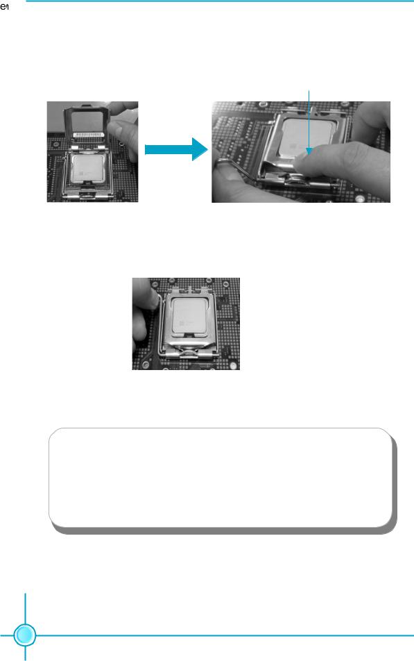
CPU
This motherboard supports single Pentium® 4 Processor including Prescott desktop CPUs in an LGA 775 package. It also supports Hyper-Threading Technology and FSB Dynamic Bus Inversion (DBI).
Installation of |
CPU |
||||
Load lever |
|
|
|
|
Load plate |
|
|
|
|
||
|
|
|
|||
Load cap
Load stiffener
 Lifted tab
8
661FX7MF/648FX7MF/648C7MF Series User Manual

Chapter 2 Installation Instructions
|
|
|
|
|
|
|
|
|
|
|
|
|
|
|
|
|
|
|
|
|
|
Correct |
|
|
|
Wrong |
|
|
|
|
|
|
|
|
|
|
|
|
|
|
|
|
|
|
|
|
|
|
9
661FX7MF/648FX7MF/648C7MF Series User Manual
Chapter 2 Installation Instructions
 Note :
Excessive temperatures will severely damage the CPU and system. Therefore, you should install CPU cooling fan and make sure that the cooling fan works normally at all times in order to prevent overheating and damaging to the CPU. Please refer to your CPU fan user guide to install it properly.
10
661FX7MF/648FX7MF/648C7MF Series User Manual

Chapter 2 Installation Instructions
CPU Qualified Vendor List
The following table lists the CPUs that have been tested and qualified for use with this motherboard.
661FX7MF & 648FX7MF Series:
Vendor |
Type |
FSB |
Frequence |
|
|
|
|
|
|
Intel |
Pentium |
(prescott) |
800MHz |
3.0G |
Intel |
Pentium |
(prescott) |
800MHz |
3.2G |
Intel |
Pentium |
(prescott) |
800MHz |
3.6G |
Intel |
Celeron -D |
533MHz |
2.93G |
|
Intel |
Celeron -D |
533MHz |
3.06G |
|
Intel |
Pentium |
(prescott) |
800MHz |
3.4G |
|
|
|
|
|
11
661FX7MF/648FX7MF/648C7MF Series User Manual

Chapter 2 Installation Instructions
Memory
This motherboard includes two, 184-pin, dual in-line memory module (DIMM) sockets. You can install corresponding PC 3200 (DDR400), PC 2700 (DDR333), or PC 2100 (DDR266) memory modules. You must install at least one memory module to ensure normal operation. If you install two modules, they must be the same speed. Mixed memory modules from different manufacturers is not recommended.
Installation of DDR Memory
1.There is only one gap in the center of the DIMM socket, and the memory module can be fixed in one direction only. Unlock a DIMM socket by pressing the module clips outward.
2.Align the memory module to the DIMM socket and insert the module vertically into the DIMM socket.
104 |
80 |
Pins |
Pins |
3. The plastic clips at both sides of the DIMM socket will lock automatically.
 Warning :
Be sure to unplug the AC power supply before adding or removing expansion cards or other system peripherals, especially the memory devices, otherwise your motherboard or the system memory might be seriously damaged.
12
661FX7MF/648FX7MF/648C7MF Series User Manual
 Loading...