


Escort 1986-1989
Chapter 1
Routine maintenance and servicing
Air cleaner element renewal . . . . . . . . . . . . . . . . . . . . . . . . . . . . . . .34
Alternator drivebelt check . . . . . . . . . . . . . . . . . . . . . . . . . . . . . . . .20
Automatic transmission fluid level check . . . . . . . . . . . . . . . . . . . . .27
Automatic transmission selector mechanism check . . . . . . . . . . . .28
Battery check . . . . . . . . . . . . . . . . . . . . . . . . . . . . . . . . . . . . . . . . . . .5
Brake components check . . . . . . . . . . . . . . . . . . . . . . . . . . . . . . . .38
Brake fluid renewal . . . . . . . . . . . . . . . . . . . . . . . . . . . . . . . . . . . . . .39
Contact breaker points adjustment - models with contact
breaker distributor . . . . . . . . . . . . . . . . . . . . . . . . . . . . . . . . . . . .13
Contact breaker points renewal . . . . . . . . . . . . . . . . . . . . . . . . . . . .25
Coolant renewal . . . . . . . . . . . . . . . . . . . . . . . . . . . . . . . . . . . . . . . .33
Crankcase emission control filter renewal . . . . . . . . . . . . . . . . . . . .35
Distributor lubrication - models with contact breaker distributor . .12
Driveshaft check . . . . . . . . . . . . . . . . . . . . . . . . . . . . . . . . . . . . . . . .29
Engine oil and filter renewal . . . . . . . . . . . . . . . . . . . . . . . . . . . . . . . .6
Exhaust manifold nut check - RS Turbo models . . . . . . . . . . . . . . . .9
Exhaust system check . . . . . . . . . . . . . . . . . . . . . . . . . . . . . . . . . . .22
Fluid leak check . . . . . . . . . . . . . . . . . . . . . . . . . . . . . . . . . . . . . . . . .8
Fluid level checks . . . . . . . . . . . . . . . . . . . . . . . . . . . . . . . . . . . . . . . .3
Front brake disc pad check . . . . . . . . . . . . . . . . . . . . . . . . . . . . . . .16
Fuel filter renewal - fuel injection engines . . . . . . . . . . . . . . . . . . . .36
Hinge and lock check and lubrication . . . . . . . . . . . . . . . . . . . . . . .31
Idle speed and mixture adjustment . . . . . . . . . . . . . . . . . . . . . . . . .10
Ignition system components check . . . . . . . . . . . . . . . . . . . . . . . . .11
Ignition timing check - models with contact breaker distributor . . .14
Intensive maintenance . . . . . . . . . . . . . . . . . . . . . . . . . . . . . . . . . . . .2
Introduction . . . . . . . . . . . . . . . . . . . . . . . . . . . . . . . . . . . . . . . . . . . .1
Manual transmission oil level check . . . . . . . . . . . . . . . . . . . . . . . . .26
Oil filler cap cleaning - OHV and HCS engines . . . . . . . . . . . . . . . . .7
Rear brake shoe lining check . . . . . . . . . . . . . . . . . . . . . . . . . . . . . .17
Road test . . . . . . . . . . . . . . . . . . . . . . . . . . . . . . . . . . . . . . . . . . . . .32
Roadwheel check . . . . . . . . . . . . . . . . . . . . . . . . . . . . . . . . . . . . . . .30
Seat belt check . . . . . . . . . . . . . . . . . . . . . . . . . . . . . . . . . . . . . . . . .19
Spark plug renewal . . . . . . . . . . . . . . . . . . . . . . . . . . . . . . . . . . . . . .24
Spark plug renewal - RS Turbo models . . . . . . . . . . . . . . . . . . . . . .15
Suspension and steering check . . . . . . . . . . . . . . . . . . . . . . . . . . . .18
Timing belt renewal . . . . . . . . . . . . . . . . . . . . . . . . . . . . . . . . . . . . .37
Turbocharger-to-manifold nut check - RS Turbo models . . . . . . . .23
Tyre checks . . . . . . . . . . . . . . . . . . . . . . . . . . . . . . . . . . . . . . . . . . . .4
Valve clearance adjustment - OHV and HCS engines . . . . . . . . . . .21
1•1
Easy, suitable for
novice with little
experience
Fairly easy, suitable
for beginner with
some experience
Fairly difficult, suitable
for competent DIY
mechanic
Difficult, suitable for
experienced DIY
mechanic
Very difficult,
suitable for expert DIY
or professional
Degrees of difficulty
Contents
1

Engine
Oil filter type . . . . . . . . . . . . . . . . . . . . . . . . . . . . . . . . . . . . . . . . . . . . . . Champion C104
Valve clearances (cold):
OHV engines:
Inlet . . . . . . . . . . . . . . . . . . . . . . . . . . . . . . . . . . . . . . . . . . . . . . . . . 0.22 mm (0.008 in)
Exhaust . . . . . . . . . . . . . . . . . . . . . . . . . . . . . . . . . . . . . . . . . . . . . . 0.59 mm (0.023 in)
HCS engines:
Inlet . . . . . . . . . . . . . . . . . . . . . . . . . . . . . . . . . . . . . . . . . . . . . . . . . 0.22 mm (0.008 in)
Exhaust . . . . . . . . . . . . . . . . . . . . . . . . . . . . . . . . . . . . . . . . . . . . . . 0.32 mm (0.012 in)
Cooling system
Recommended antifreeze concentration . . . . . . . . . . . . . . . . . . . . . . . . 45% by volume
Fuel system
Idle speed:
Carburettor models:
All except Weber 2V TLDM carburettor . . . . . . . . . . . . . . . . . . . . . 750 to 850 rpm
Weber 2V TLDM carburettor . . . . . . . . . . . . . . . . . . . . . . . . . . . . . . 700 to 800 rpm
Bosch K-Jetronic fuel injection models . . . . . . . . . . . . . . . . . . . . . . . 750 to 850 rpm
Bosch KE-Jetronic fuel injection models:
1985 models . . . . . . . . . . . . . . . . . . . . . . . . . . . . . . . . . . . . . . . . . . 800 to 900 rpm
1986 models onwards . . . . . . . . . . . . . . . . . . . . . . . . . . . . . . . . . . . 920 to 960 rpm
Electronic Fuel Injection (EFI) models . . . . . . . . . . . . . . . . . . . . . . . . . 900 ± 50 rpm
Idle mixture CO content:
Bosch K-Jetronic fuel injection models . . . . . . . . . . . . . . . . . . . . . . . 1.0 to 1.5 %
Bosch KE-Jetronic fuel injection models:
1985 models . . . . . . . . . . . . . . . . . . . . . . . . . . . . . . . . . . . . . . . . . . 0.25 to 0.75%
1986 models onwards . . . . . . . . . . . . . . . . . . . . . . . . . . . . . . . . . . . 0.5 to 1.1%
Electronic Fuel Injection (EFI) models . . . . . . . . . . . . . . . . . . . . . . . . . 0.8 ± 0.25% (cooling fan running)
Air filter element type:
1.1 litre and 1.3 litre OHV engines . . . . . . . . . . . . . . . . . . . . . . . . . . . Champion W153
1.1 litre and 1.3 litre HCS engines . . . . . . . . . . . . . . . . . . . . . . . . . . . Champion W225
1.1 litre and 1.3 litre CVH engines . . . . . . . . . . . . . . . . . . . . . . . . . . . Champion W127
1.4 litre CVH engine:
Carburettor engines . . . . . . . . . . . . . . . . . . . . . . . . . . . . . . . . . . . . Champion W179
Central Fuel Injection (CFI) engines . . . . . . . . . . . . . . . . . . . . . . . . Champion W201
1.6 litre CVH engine (except XR3 models):
Up to 1986 . . . . . . . . . . . . . . . . . . . . . . . . . . . . . . . . . . . . . . . . . . . Champion W169
1986 to October 1988 . . . . . . . . . . . . . . . . . . . . . . . . . . . . . . . . . . . Champion W201
October 1988 on . . . . . . . . . . . . . . . . . . . . . . . . . . . . . . . . . . . . . . . Champion W226
1.6 litre CVH engine (XR3 models) . . . . . . . . . . . . . . . . . . . . . . . . . Champion W201
Ignition system
Contact breaker points gap:
Bosch distributor . . . . . . . . . . . . . . . . . . . . . . . . . . . . . . . . . . . . . . . . . 0.40 to 0.50 mm (0.016 to 0.02 in)
Lucas distributor . . . . . . . . . . . . . . . . . . . . . . . . . . . . . . . . . . . . . . . . . 0.40 to 0.59 mm (0.016 to 0.023 in)
Dwell angle (contact breaker ignition system) . . . . . . . . . . . . . . . . . . . . 48º to 52º
Ignition timing *:
OHV engines:
Up to 1984 (contact breaker) . . . . . . . . . . . . . . . . . . . . . . . . . . . . . . . 12º BTDC at idle speed
1984-on (contact breaker) and all electronic ignition . . . . . . . . . . . . . 6º BTDC at idle speed
CVH engines (all models) . . . . . . . . . . . . . . . . . . . . . . . . . . . . . . . . . . . . 12º BTDC at idle speed
* Note:
Ignition timing on models with either a Distributorless Ignition Sytem (DIS) or a programmed ignition system (ESC) cannot be adjusted.
Refer to Chapter 5, Part B for further information.
Spark plugs:
Type:
OHV and HCS engines . . . . . . . . . . . . . . . . . . . . . . . . . . . . . . . . . . . . Champion RS9YCC or RS9YC
CVH engines:
Carburettor models . . . . . . . . . . . . . . . . . . . . . . . . . . . . . . . . . . . . . Champion RC7YCC or RC7YC
Bosch K-Jetronic fuel injection and
Electronic Fuel Injection (EFI) models . . . . . . . . . . . . . . . . . . . . . . . Champion C6YCC or RC6YC
Bosch KE-Jetronic fuel injection models . . . . . . . . . . . . . . . . . . . . Champion C61YC
Central Fuel Injection (CFI) models . . . . . . . . . . . . . . . . . . . . . . . . . Champion RC7YCC or RC7YC4
Electrode gap:
All except HCS and CFI models:
RS9YCC, RC7YCC, C6YCC spark plugs . . . . . . . . . . . . . . . . . . . . 0.8 mm (0.032 in)
RS9YC, RC7YC, RC6YC, . . . . . . . . . . . . . . . . . . . . . . . . . . . . . . . . 0.7 mm (0.028 in)
HCS and CFI models . . . . . . . . . . . . . . . . . . . . . . . . . . . . . . . . . . . . . 1.0 mm (0.039 in)
1•2 Servicing Specifications

Servicing Specifications 1•3
1
Brakes
Minimum front brake disc pad thickness . . . . . . . . . . . . . . . . . . . . . . . . 1.5 mm (0.06 in)
Minimum rear brake shoe lining thickness . . . . . . . . . . . . . . . . . . . . . . . 1.0 mm (0.04 in)
Tyres
Tyre pressures . . . . . . . . . . . . . . . . . . . . . . . . . . . . . . . . . . . . . . . . . . . . See “Weekly checks” on page 0•16
Torque wrench settings Nm lbf ft
Exhaust manifold nuts - RS Turbo models . . . . . . . . . . . . . . . . . . . . . . . 14 to 17 10 to 13
Turbocharger-to-manifold nuts . . . . . . . . . . . . . . . . . . . . . . . . . . . . . . . 21 to 26 15 to 19
Spark plugs:
OHV and HCS engines . . . . . . . . . . . . . . . . . . . . . . . . . . . . . . . . . . . . 13 to 20 10 to 15
CVH engines . . . . . . . . . . . . . . . . . . . . . . . . . . . . . . . . . . . . . . . . . . . . 25 to 38 18 to 28
Seat belt anchor bolts . . . . . . . . . . . . . . . . . . . . . . . . . . . . . . . . . . . . . . . 29 to 41 21 to 30
Roadwheel bolts . . . . . . . . . . . . . . . . . . . . . . . . . . . . . . . . . . . . . . . . . . . 70 to 100 52 to 74
Capacities
Engine oil (drain and refill)
OHV engine:
With filter change . . . . . . . . . . . . . . . . . . . . . . . . . . . . . . . . . . . . . . . . 3.25 litres (5.7 pints)
Without filter change . . . . . . . . . . . . . . . . . . . . . . . . . . . . . . . . . . . . . . 2.75 litres (4.8 pints)
CVH engine:
Carburettor engines with filter change:
Pre-July 1982 . . . . . . . . . . . . . . . . . . . . . . . . . . . . . . . . . . . . . . . . . 3.75 litres (6.6 pints)
July 1982 onwards . . . . . . . . . . . . . . . . . . . . . . . . . . . . . . . . . . . . . 3.50 litres (6.2 pints)
Carburettor engines without filter change:
Pre-July 1982 . . . . . . . . . . . . . . . . . . . . . . . . . . . . . . . . . . . . . . . . . 3.50 litres (6.2 pints)
July 1982 onwards . . . . . . . . . . . . . . . . . . . . . . . . . . . . . . . . . . . . . 3.25 litres (5.7 pints)
Fuel-injected engines with filter change . . . . . . . . . . . . . . . . . . . . . . . 3.85 litres (6.8 pints)
Fuel-injected engines without filter change . . . . . . . . . . . . . . . . . . . . 3.60 litres (6.3 pints)
Fuel tank
All models (except XR3i and Van) pre-May 1983 . . . . . . . . . . . . . . . . . . 40 litres (8.8 gallons)
All other models (except Van) . . . . . . . . . . . . . . . . . . . . . . . . . . . . . . . . . 48 litres (10.6 gallons)
Van . . . . . . . . . . . . . . . . . . . . . . . . . . . . . . . . . . . . . . . . . . . . . . . . . . . . . 50 litres (11.0 gallons)
Cooling system
1.1 litre OHV engine . . . . . . . . . . . . . . . . . . . . . . . . . . . . . . . . . . . . . . . . 6.7 litres (11.8 pints)
1.1 litre CVH engine:
With small radiator . . . . . . . . . . . . . . . . . . . . . . . . . . . . . . . . . . . . . . . 6.2 litres (11.0 pints)
With large radiator . . . . . . . . . . . . . . . . . . . . . . . . . . . . . . . . . . . . . . . . 7.2 litres (12.6 pints)
1.3 litre OHV engine . . . . . . . . . . . . . . . . . . . . . . . . . . . . . . . . . . . . . . . . 7.1 litres (12.5 pints)
1.3 litre CVH engine:
Pre-1986 . . . . . . . . . . . . . . . . . . . . . . . . . . . . . . . . . . . . . . . . . . . . . . . 7.1 litres (12.5 pints)
1986 onwards . . . . . . . . . . . . . . . . . . . . . . . . . . . . . . . . . . . . . . . . . . . 7.6 litres (13.3 pints)
1.4 litre CVH engine . . . . . . . . . . . . . . . . . . . . . . . . . . . . . . . . . . . . . . . . 7.6 litres (13.3 pints)
1.6 litre CVH engine:
Pre-1986 . . . . . . . . . . . . . . . . . . . . . . . . . . . . . . . . . . . . . . . . . . . . . . . 6.9 litres (12.1 pints)
1986 onwards . . . . . . . . . . . . . . . . . . . . . . . . . . . . . . . . . . . . . . . . . . . 7.8 litres (13.7 pints)
Transmission
4-speed manual . . . . . . . . . . . . . . . . . . . . . . . . . . . . . . . . . . . . . . . . . . . 2.8 litres (4.9 pints)
5-speed manual . . . . . . . . . . . . . . . . . . . . . . . . . . . . . . . . . . . . . . . . . . . 3.1 litres (5.5 pints)
Automatic transmission . . . . . . . . . . . . . . . . . . . . . . . . . . . . . . . . . . . . . 7.9 litres (13.9 pints)
The maintenance intervals in this manual are provided with the
assumption that you, not the dealer, will be carrying out the work. These
are the minimum maintenance intervals recommended by the
manufacturer for vehicles driven daily. If you wish to keep your vehicle
in peak condition at all times, you may wish to perform some of these
procedures more often. We encourage frequent maintenance, because
it enhances the efficiency, performance and resale value of your vehicle.
If the vehicle is driven in dusty areas, used to tow a trailer, or driven
frequently at slow speeds (idling in traffic) or on short journeys, more
frequent maintenance intervals are recommended.
When the vehicle is new, it should be serviced by a factoryauthorised dealer service department, in order to preserve the factory
warranty.
Ford Escort maintenance schedule

1•4 Maintenance schedule
Every 6000 miles (10 000 km) or
6 months – whichever comes first
In addition to all the items in the 250 mile (400 km) service, carry
out the following:
mm Renew the engine oil and filter (Section 6)
mm On OHV and HCS engines, remove and clean the oil
filler cap (Section 7)
mm Check the hoses, hose clips and visible joint gaskets for
leaks and any signs of corrosion or deterioration (Section 8)
mm Visually check the fuel pipes and hoses for security,
chafing, leaks and corrosion (Section 8)
mm Check the fuel tank for leaks and any sign of damage or
corrosion (Section 8)
mm On RS Turbo models check the tightness of the
exhaust manifold retaining nuts (Section 9)
mm Check and if necessary adjust the idle speed and
mixture settings (Section 10)
mm Clean the distributor cap, coil tower and HT leads and
check for tracking (Section 11)
mm On contact breaker point distributors lubricate the
distributor shaft and cam (Section 12)
mm On contact breaker point distributors check and if
necessary adjust the points gap (dwell angle), then
check the ignition timing (Sections 13 and 14)
mm On RS Turbo models renew the spark plugs (Section 15)
mm Check the front disc pad thickness (Section 16)
mm Check the rear brake shoe lining thickness (Section 17)
mm Check the steering and suspension components for
any signs of damage and wear (Section 18)
mm Check the security of the front suspension lower arm
balljoint (Section 18)
mm Check the seat belt webbing for cuts or damage and
check the seat belt operation (Section 19)
mm Carefully inspect the paintwork for damage and the
bodywork for corrosion (Chapter 11)
mm Check the condition and adjustment of the alternator
drivebelt (Section 20)
Every 12 000 miles (20 000 km) or
12 months - whichever comes first
In addition to all the items in the 6000 mile (10 000 km) service,
carry out the following:
mm On OHV and HCS engines check and if necessary
adjust the valve clearances (Section 21)
mm Check the exhaust system condition and security
(Section 22)
mm On RS Turbo models check the tightness of the
turbocharger-to-manifold nuts (Section 23)
mm Renew the spark plugs (Sections 24 and 15)
mm On contact breaker point distributors renew the contact
breaker points (Section 25)
mm Check and if necessary top-up the manual transmission
oil (Section 26)
mm Check the automatic transmission fluid level - where
applicable (Section 27)
mm Check the operation of the automatic transmission
selector mechanism (Section 28)
mm Check the driveshafts for damage or distortion and
check the condition of the constant velocity joint
bellows (Section 29)
mm Inspect the roadwheels for damage (Section 30)
mm Check the tightness of the roadwheel bolts (Section 30)
mm Lubricate all hinges, door locks, check straps and the
bonnet release mechanism (Section 31)
mm Check the operation of all door, tailgate, bonnet release
and window regulator components (Section 31)
mm Carry out a road test (Section 32)
Every 36 000 miles (60 000 km) or
3 years - whichever comes first
In addition to all the items listed in the previous services, carry out
the following:
mm On CVH engines renew the timing belt (Section 37)
mm Make a thorough inspection of all brake components
and rubber seals for signs of leaks, general
deterioration and wear (Section 38)
mm Renew the brake fluid (Section 39)
Every 24 000 miles (40 000 km) or
2 years - whichever comes first
In addition to all the items in the 12 000 mile (20 000 km) and
6000 mile (10 000 km) services, carry out the following:
mm Renew the coolant (Section 33)
mm Renew the air cleaner element (Section 34)
mm On CVH engines renew the crankcase emission control
filter (Section 35)
mm On fuel-injected engines renew the fuel filter (Section 36)
Every 250 miles (400 km) or weekly
mm See "Weekly checks"
Maintenance - Component location 1•5
1
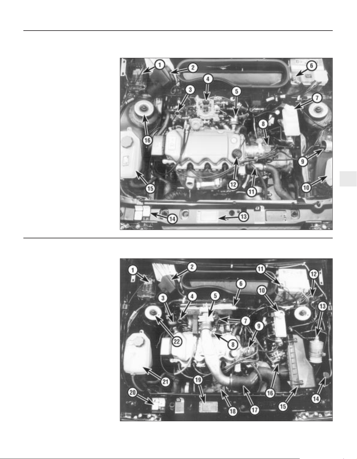
1 Fuse and relay box
2 Windscreen wiper motor
3 Engine oil dipstick
4 Carburettor
5 Fuel pump
6 Battery negative terminal
7 Brake master cylinder reservoir
8 Distributor
9 Ignition coil
10 Washer reservoir
11 Thermostat housing
12 Oil filler cap
13 Vehicle identification plate
14 Engine tuning decal
15 Cooling system expansion tank
16 Suspension strut top mounting
Engine and under bonnet component location on 1986 1.4 litre models (air cleaner removed for clarity)
1 Fuse and relay box
2 Windscreen wiper motor
3 Crankcase emission control filter
4 Engine oil dipstick
5 Throttle housing
6 Inlet manifold
7 Throttle position sensor
8 Charge air temperature sensor
9 Distributor
10 Brake master cylinder reservoir
11 Battery negative terminal
12 Ignition coil
13 Fuel filter
14 Washer reservoir
15 Air cleaner
16 Fuel distributor
17 Inlet air hose
18 Turbocharger
19 Vehicle identification plate
20 Engine tuning decal
21 Cooling system expansion tank
22 Suspension strut top mounting
Engine and under bonnet component locations on 1986 RS Turbo models
1•6 Maintenance - Component location
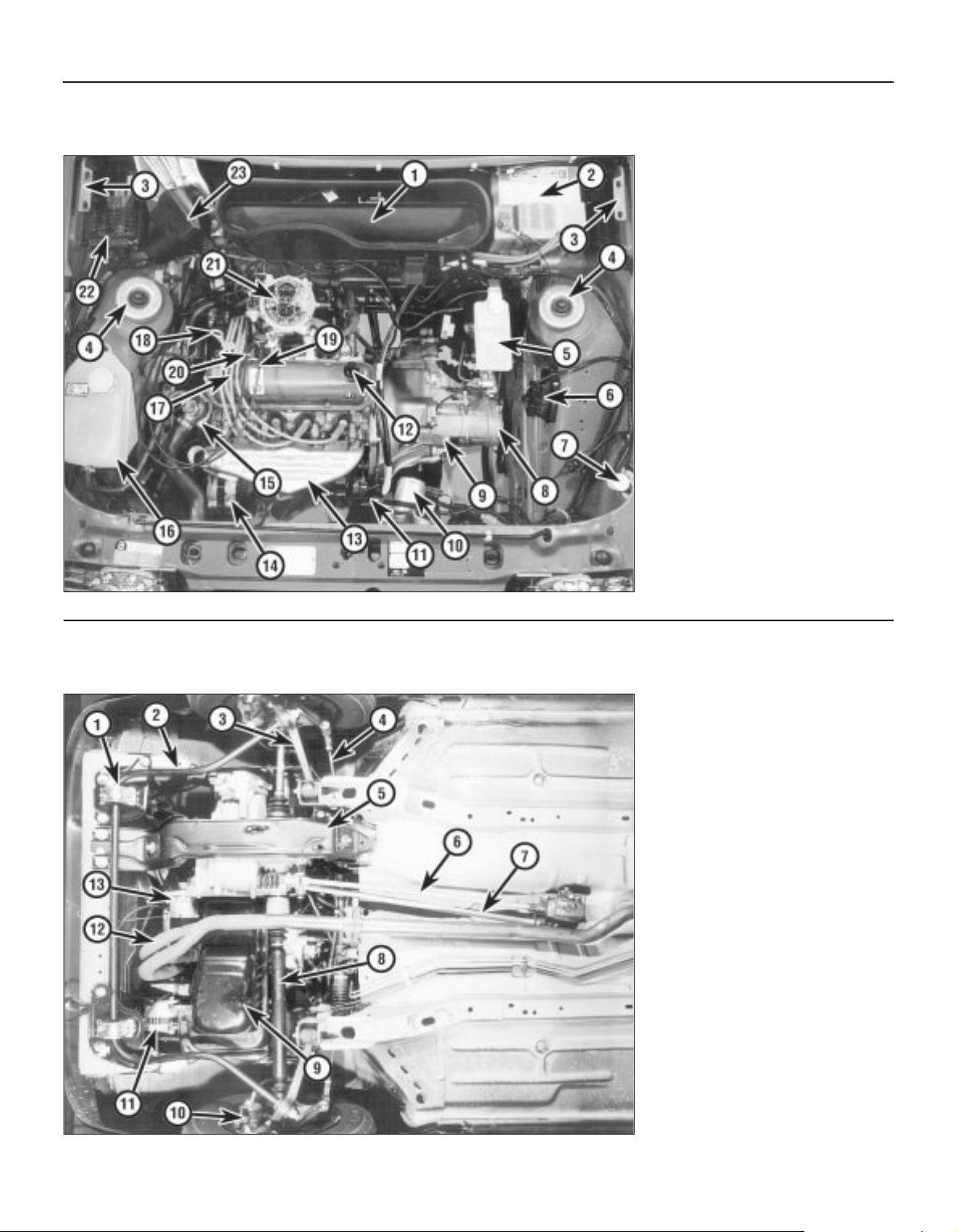
1 Ventilation air inlet duct
2 Battery
3 Bonnet hinge
4 Suspension strut upper mounting
5 Brake system fluid reservoir
6 Ignition system ESC module
7 Windscreen washer reservoir filler cap
8 Transmission housing
9 Clutch release lever
10 Cooling fan motor
11 Starter motor
12 Engine oil filler neck (cap removed)
13 Exhaust manifold shield
14 Alternator
15 Coolant thermostat and fan thermal
switch
16 Coolant expansion tank
17 Spark plug HT leads
18 Engine oil dipstick
19 Throttle cable
20 Choke cable
21 Carburettor
22 Fusebox
23 Windscreen wiper motor
Engine and underbonnet components location on 1989 1.3 litre HCS model (air cleaner removed for clarity)
1 Anti-roll bar clamp
2 Anti-roll bar
3 Front suspension lower arm
4 Steering tie-rod
5 Transmission support crossmember
6 Gearchange rod
7 Gearchange stabiliser
8 Driveshaft
9 Engine oil drain plug
10 Brake caliper
11 Alternator
12 Exhaust front pipe
13 Starter motor
Front underbody view of a 1986 1.4 litre Saloon model
Maintenance procedures 1•7
1
General information
This Chapter is designed to help the home
mechanic maintain his/her vehicle for safety,
economy, long life and peak performance.
The Chapter contains a master
maintenance schedule, followed by Sections
dealing specifically with each task on the
schedule. Visual checks, adjustments,
component renewal and other helpful items
are included. Refer to the accompanying
illustrations of the engine compartment and
the underside of the vehicle for the locations
of the various components.
Servicing of your vehicle in accordance with
the mileage/time maintenance schedule and
the following Sections will provide a planned
maintenance program, which should result in
a long and reliable service life. This is a
comprehensive plan, so maintaining some
items but not others at the specified service
intervals will not produce the same results.
As you service your vehicle, you will
discover that many of the procedures can and should - be grouped together because of
the particular procedure being performed, or
because of the close proximity of two
otherwise unrelated components to one
another. For example, if the vehicle is raised
for any reason, the exhaust can be inspected
at the same time as the suspension and
steering components.
The first step in this maintenance program
is to prepare yourself before the actual work
begins. Read through all the Sections relevant
to the work to be carried out, then make a list
and gather together all the parts and tools
required. If a problem is encountered, seek
advice from a parts specialist, or a dealer
service department.
If, from the time the vehicle is new, the
routine maintenance schedule is followed
closely and frequent checks are made of fluid
levels and high wear items, as suggested
throughout this manual, the engine will be
kept in relatively good running condition and
the need for additional work will be minimised.
It is possible that there will be times when
the engine is running poorly due to the lack of
regular maintenance. This is even more likely
if a used vehicle, which has not received
regular and frequent maintenance checks, is
purchased. In such cases, additional work
may need to be carried out, outside of the
regular maintenance intervals.
If engine wear is suspected, a compression
test will provide valuable information
regarding the overall performance of the main
internal components. Such a test can be used
as a basis to decide on the extent of the work
to be carried out. If for example a
compression test indicates serious internal
engine wear, conventional maintenance as
described in this Chapter will not greatly
improve the performance of the engine, and
may prove a waste of time and money, unless
extensive overhaul work is carried out first.
The following series of operations are those
most often required to improve the
performance of a generally poor-running
engine.
a) Clean, inspect and test the battery
(Section 5).
b) Check the levels of all the engine related
fluids (Section 3).
c) Check the condition and tension of the
alternator drivebelt (Section 20).
d) Check the condition of the spark plugs
and renew if necessary (Section 15).
e) Check the condition of the air cleaner
element, and renew if necessary (Section 34).
f) Check the condition of all hoses and
check for fluid leaks.
g) Check and if necessary adjust the idle
speed (where possible) (Section 10).
2 Intensive maintenance
1 Introduction
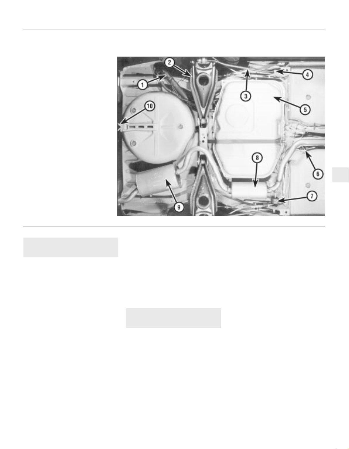
1 Fuel filler pipe
2 Suspension lower arm
3 Tie-bar
4 Tie-bar front mounting
5 Fuel tank
6 Handbrake cable adjuster
7 Exhaust mounting
8 Exhaust intermediate silencer
9 Exhaust rear silencer
10 Rear towing eye
Rear underbody view of a 1986 1.4 litre Saloon model
1 Frequent oil and filter changes are the most
important preventative maintenance
procedures that can be undertaken by the DIY
owner. As engine oil ages, it becomes diluted
and contaminated, which leads to premature
engine wear.
2 Before starting this procedure, gather
together all the necessary tools and materials.
Also make sure that you have plenty of clean
rags and newspapers handy to mop up any
spills. Ideally, the engine oil should be warm,
as it will drain better and more built-up sludge
will be removed with it. Take care, however,
not to touch the exhaust or any other hot
parts of the engine when working under the
vehicle. To avoid any possibility of scalding,
and to protect yourself from possible skin
irritants and other harmful contaminants in
used engine oils, it is advisable to wear rubber
gloves when carrying out this work. Access to
the underside of the vehicle will be greatly
improved if it can be raised on a lift, driven
onto ramps or jacked up and supported on
axle stands (see “Jacking and Vehicle
Support”). Whichever method is chosen,
make sure that the vehicle remains as level as
possible, to enable the oil to drain fully.
3 Remove the oil filler cap from the rocker cover,
then position a container beneath the sump.
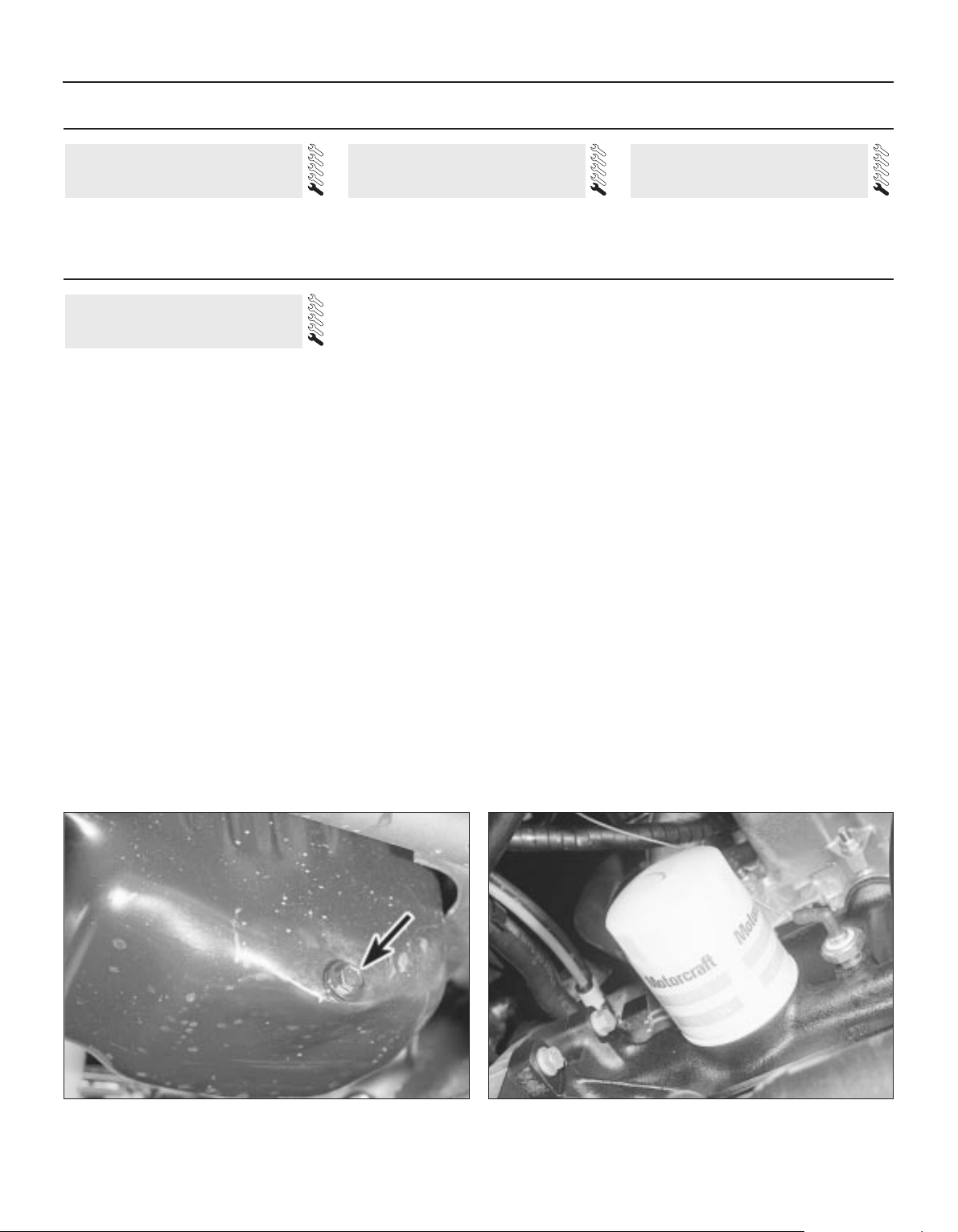
4 Clean the drain plug and the area around it,
then slacken it using a suitable socket or
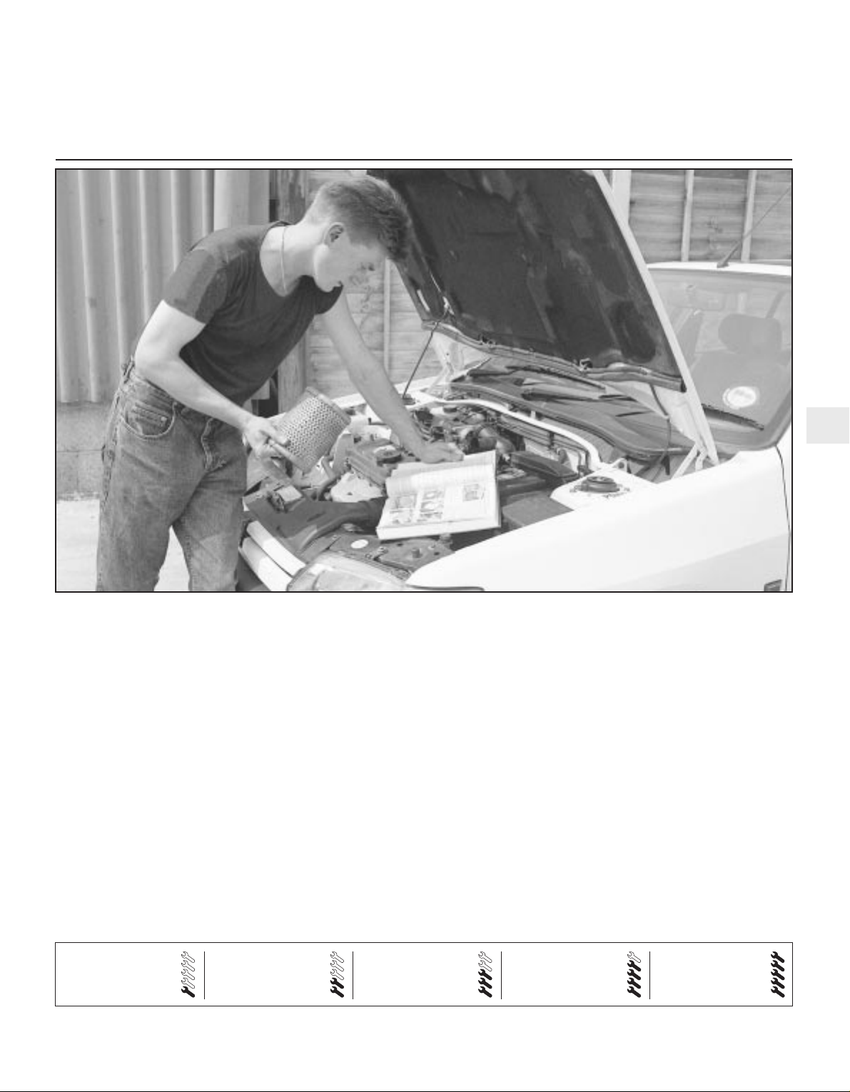
spanner (see illustration). If possible, try to
keep the plug pressed into the sump while
unscrewing it by hand the last couple of turns.
As the plug releases from the threads, move it
away sharply so the stream of oil issuing from
the sump runs into the container, not up your
sleeve!
5 Allow some time for the old oil to drain,
noting that it may be necessary to reposition
the container as the oil flow slows to a trickle.
6 After all the oil has drained, wipe off the
drain plug with a clean rag and check the
condition of the sealing washer. Renew the
washer if necessary. Clean the area around
the drain plug opening, then refit and tighten
the plug to the specified torque setting.
7 Move the container into position under the
oil filter. The oil filter is located at the rear of
the cylinder block, and is accessible from
under the vehicle (see illustration)
8 Using an oil filter removal tool, slacken the
filter initially. Loosely wrap some rags around
the oil filter, then unscrew it and immediately
position it with its open end uppermost to
prevent further spillage of oil. Remove the oil
filter from the engine compartment and empty
the oil into the container.
9 Use a clean rag to remove all oil, dirt and
sludge from the filter sealing area on the
engine. Check the old filter to make sure that
the rubber sealing ring hasn’t stuck to the
engine. If it has, carefully remove it.
10 Apply a light coating of clean oil to the
sealing ring on the new filter, then screw it into
position on the engine. Tighten the filter firmly
by hand only - do not use any tools. Wipe
clean the exterior of the oil filter.
11 Remove the old oil and all tools from
under the vehicle, then (if applicable) lower the
vehicle to the ground.
12 Fill the engine with the specified quantity
and grade of oil, as described in “Weekly
checks”. Pour the oil in slowly, otherwise it
may overflow from the top of the rocker cover.
Check that the oil level is up to the correct
level on the dipstick, then refit and tighten the
oil filler cap.
13 Run the engine for a few minutes, and
check that there are no leaks around the oil
filter seal and the sump drain plug.
14 Switch off the engine and wait a few
minutes for the oil to settle in the sump once
more. With the new oil circulated and the filter
now completely full, recheck the level on the
dipstick and add more oil if necessary.
15 Dispose of the used engine oil safely with
reference to “General repair procedures” in
the Reference Sections at the end of this
manual.
6 Engine oil and filter renewal
Every 6000 miles or 6 months
1•8 Maintenance procedures
See “Weekly checks” starting on Page 0•10. See “Weekly checks” starting on Page 0•10. See “Weekly checks” starting on Page 0•10.
5 Battery check4 Tyre checks3 Fluid level checks
Weekly checks
6.7 Oil filter location - CVH engine6.4 Engine oil drain plug (arrowed) -
CVH engine
Every 6000 miles or 6 Months 1•9
1
1 Simply pull the oil filler cap from the rocker
cover and, where applicable, disconnect the
hose(s) from the cap.
2 Inspect the filler cap, and if necessary clean
the cap using clean petrol to remove any
deposits.
3 Ensure that the cap is completely dry
before refitting.
1 Visually inspect the engine joint faces,
gaskets and seals for any signs of water or oil
leaks. Pay particular attention to the areas
around the rocker cover, cylinder head, oil
filter and sump joint faces. Bear in mind that
over a period of time some very slight
seepage from these areas is to be expected
but what you are really looking for is any
indication of a serious leak. Should a leak be
found, renew the offending gasket or oil seal
by referring to the appropriate Chapter(s) in
this manual.
2 Similarly, check the transmission for oil
leaks, and investigate and rectify and
problems found.
3 Check the security and condition of all the
engine related pipes and hoses. Ensure that
all cable-ties or securing clips are in place and
in good condition. Clips which are broken or
missing can lead to chafing of the hoses,
pipes or wiring which could cause more
serious problems in the future.
4 Carefully check the condition of all coolant,
fuel and brake hoses. Renew any hose which
is cracked, swollen or deteriorated. Cracks
will show up better if the hose is squeezed.
Pay close attention to the hose clips that
secure the hoses to the system components.
Hose clips can pinch and puncture hoses,
resulting in leaks. If wire type hose clips are
used, it may be a good idea to replace them
with screw-type clips.
5 With the vehicle raised, inspect the fuel
tank and filler neck for punctures, cracks and
other damage. The connection between the
filler neck and tank is especially critical.
Sometimes a rubber filler neck or connecting
hose will leak due to loose retaining clamps or
deteriorated rubber.
6 Similarly, inspect all brake hoses and metal
pipes. If any damage or deterioration is
discovered, do not drive the vehicle until the
necessary repair work has been carried out.
Renew any damaged sections of hose or pipe.
7 Carefully check all rubber hoses and metal
fuel lines leading away from the petrol tank.
Check for loose connections, deteriorated
hoses, crimped lines and other damage. Pay
particular attention to the vent pipes and
hoses which often loop up around the filler
neck and can become blocked or crimped.
Follow the lines to the front of the vehicle
carefully inspecting them all the way. Renew
damaged sections as necessary.
8 From within the engine compartment,
check the security of all fuel hose attachments
and pipe unions, and inspect the fuel hoses
and vacuum hoses for kinks, chafing and
deterioration.
9 Where applicable, check the condition of
the oil cooler hoses and pipes.
10 Check the condition of all exposed wiring
harnesses.
11 Also check the engine and transmission
components for signs of fluid leaks.
Check the tightness of the exhaust
manifold securing nuts using a torque wrench.
Note: Before carrying out any carburettor
adjustment, ensure that the contact breaker
points, ignition timing and spark plug gaps (as
applicable) are set as specified and that the
distributor is operating correctly (where
applicable). To carry out the adjustments an
accurate tachometer will be required and the
use of an exhaust gas analyser (CO meter) is
also preferable.
Models with Ford VV carburettor
Idle speed
1 With the engine at normal operating
temperature, connect a tachometer in
accordance with the manufacturer’s
instructions.
2 Disconnect the wiring multi-plug from the
radiator cooling fan thermostatic switch in the
thermostat housing and bridge the two
contacts in the plug using a suitable length of
wire. This is necessary so that the cooling fan
runs continuously during adjustment.
3 On automatic transmission models slacken
the adjuster screw on the throttle valve shaft
lever to give clearance of 2 to 3 mm (0.079 to
0.118 in) - see Chapter 7, Part B.
4 Ensure that the air cleaner is fitted and that
its vacuum hoses are not in any way trapped
or pinched, particularly between the air cleaner
body and the top face of the carburettor.
5 Run the engine at 3000 rpm for 30 seconds,
then allow it to idle and note the idle speed. If
using an exhaust gas analyser it should be
noted that initially the CO% reading will rise,
but then fall and stabilise after a period of 5 to
25 seconds. The CO reading should then be
as specified.
Idle mixture
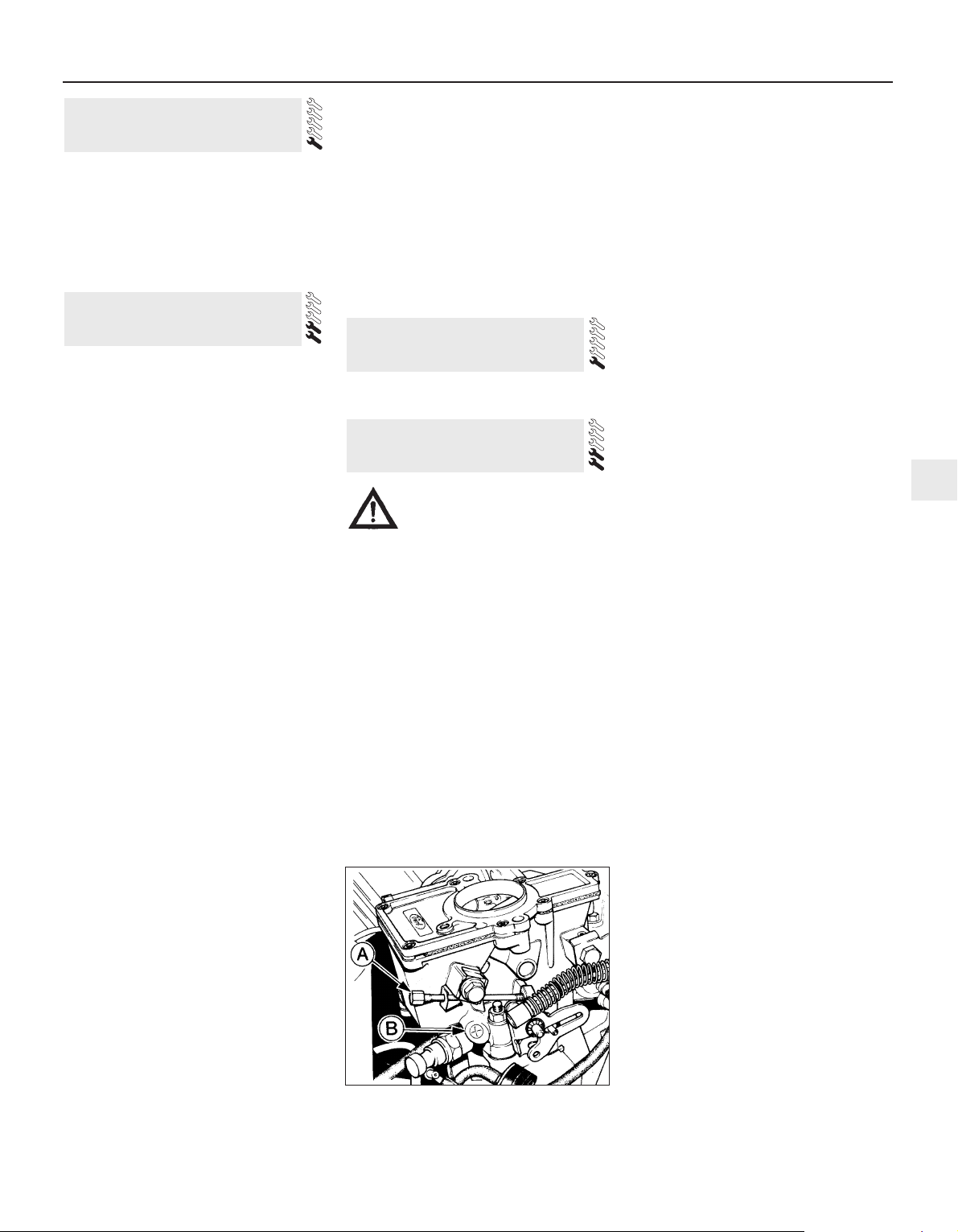
6 If necessary, adjust the idle speed
adjustment screw to give the specified idle
speed (see illustration).
7 Adjustment of the CO content (mixture) is
not normally required during routine
maintenance, but if the reading noted in
paragraph 5 is not as given in the
Specifications first remove the tamperproof
plug, prising it free using a small screwdriver.
8 Run the engine at 3000 rpm for 30 seconds,
then allow it to idle. Adjust the mixture screw
(see illustration 10.6) within 30 seconds. If
more time is required run the engine at 3000
rpm again for 30 seconds.
9 Adjust the idle speed if necessary and
recheck the CO content.
10 Fit a new tamperproof plug to the mixture
adjuster screw on completion. It should be
noted that mixture adjustment without a CO
analyser is not accurate and therefore not
recommended.
11 On completion disconnect the
instruments, remove the cooling fan bridging
wire and reconnect the multi-plug.
12 On automatic transmission models adjust
the downshift linkage (Chapter 7, Part B).
Models with Weber 2V carburettor
13 The procedure is the same as for the Ford
VV carburettor as described previously in this
Section, but the adjusting screw locations are
as shown (see illustrations).
Models with Bosch K-Jetronic
fuel injection system
14 The idle speed and fuel mixture
adjustments will normally only be required
after the installation of new components.
10 Idle speed and mixture
adjustment
9 Exhaust manifold nut check -
RS Turbo models
8 Fluid leak check
7 Oil filler cap cleaning - OHV
and HCS engines
10.6 Idle speed adjustment screw (A) and
mixture adjustment screw (B) - Ford VV
carburettor
Caution: Certain adjustment
points in the fuel system are
protected by “tamperproof”
caps, plugs or seals. In some
EEC countries (though not yet in the UK)
it is an offence to drive a vehicle with
broken or missing tamperproof seals.
Before disturbing a tamperproof seal,
satisfy yourself that you will not be
breaking any local or national laws by
doing so, and fit a new seal after
adjustment is complete where required by
law. Do not break tamperproof seals on a
vehicle which is still under warranty.

Refer to the caution at the beginning of this
Section before proceeding.
15 On early models the idle speed
adjustment screw is located on the rear of the
throttle housing, but access is severely limited
unless the heater plenum chamber top cover
is removed as described in Chapter 4, Part B
(see illustration).
16 On later models the idle speed adjustment
screw is located on top of the throttle housing
beneath a tamperproof plug (see illustration).
Hook out the plug with a sharp pointed tool to
gain access.
17 Before making any adjustments, warm the
engine up to normal operating temperature
and connect a tachometer in accordance with
the manufacturer’s instructions.
18 Increase the engine speed to 3000 rpm
and hold it at this speed for 30 seconds, then
allow the engine to idle, check the tachometer
reading and if necessary turn the idle speed
adjustment screw as required until the engine
is idling at the specified speed.
19 To check the mixture adjustment an
exhaust gas analyser is needed and should be
connected in accordance with the
manufacturer’s instructions. A 3 mm Allen key
will also be required to make any adjustments.
20 Before making any adjustments to the
mixture, ensure that the idle speed is correct.
21 Remove the tamperproof plug from the
top of the mixture adjustment screw tube on
top of the fuel distributor (see illustration).
22 Stabilise the exhaust gases (paragraph 18).
23 Insert the Allen key into the mixture screw
tube and engage the adjusting screw. Turn
the screw as necessary until the correct CO
reading is obtained, then if required readjust
the idling speed.
24 If the mixture adjustment cannot be
finalised within 30 seconds from the moment
of stabilising the exhaust gases, repeat the
operations in paragraph 18 before continuing
the adjustment procedure.
25 On completion fit a new tamperproof plug
and disconnect the tachometer and exhaust
gas analyser.
Models with Bosch KE-Jetronic
fuel injection system
26 The idle speed and fuel mixture
adjustments will normally only be required
after the installation of new components.
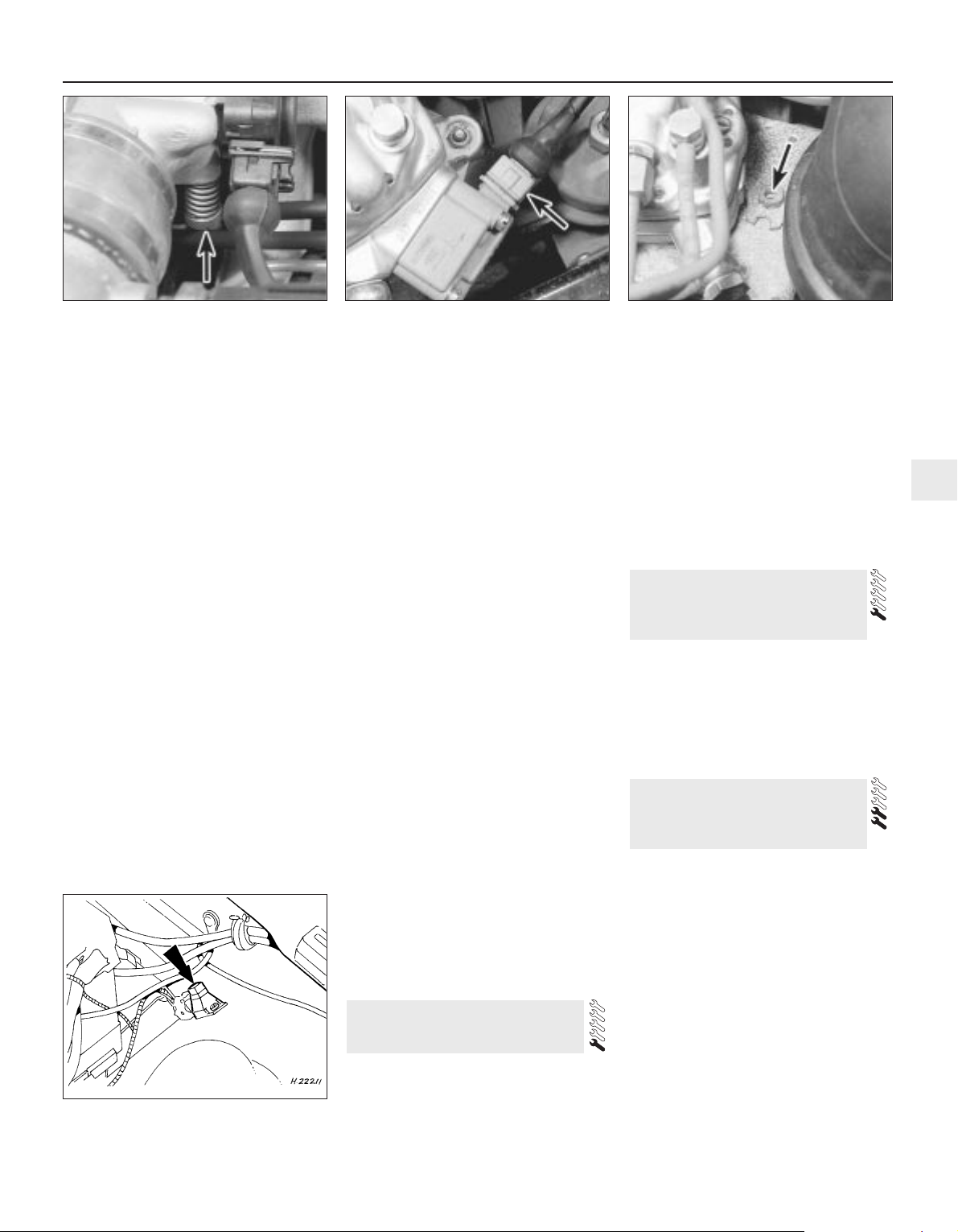
27 The idle speed adjustment screw is
located on the side of the throttle housing
(see illustration).
28 Before making any adjustments, warm the
engine up to normal operating temperature
and connect a tachometer in accordance with
the manufacturer’s instructions.
29 Disconnect the wiring multi-plug at the
pressure actuator on the side of the fuel
distributor (see illustration).
30 Increase the engine speed to 3000 rpm
and hold it at this speed for 30 seconds, then
allow the engine to idle. Check the
tachometer reading and if necessary turn the
1•10 Every 6000 miles or 6 Months
10.16 K-Jetronic system idle speed
adjustment screw (arrowed) on later
models
10.13b Weber 2V carburettor mixture adjustment screw (A) and
idle speed adjustment screw (B) - 1.6 litre models
10.15 Idle speed adjustment screw
(arrowed) on early K-Jetronic systems
10.13c Idle speed screw (A) and mixture
adjustment screw (B) on Weber 2V TLDM
carburettor (1.1 and 1.3 HCS engines)
10.13a Weber 2V carburettor idle speed adjustment screw (A) and
mixture screw (B) - XR3 and 1.4 litre models
10.21 K-Jetronic system mixture
adjustment screw location (arrowed)
Every 6000 miles or 6 Months 1•11
1
idle speed adjustment screw as required until
the engine is idling at the specified speed.
31 To check the mixture adjustment an
exhaust gas analyser is needed and should be
connected in accordance with the
manufacturer’s instructions. A 3 mm Allen key
will also be required to make any adjustments.
32 Before proceeding ensure that the idle
speed is correct.
33 Unscrew the tamperproof plug from the
mixture adjustment orifice on top of the fuel
distributor (see illustration).
34 Stabilise the exhaust gases (paragraph 30).
35 Insert the Allen key into the mixture
adjustment orifice and push down to engage
the adjustment screw. Turn the adjustment
screw clockwise to increase the CO reading
and anti-clockwise to decrease it. Remove the
Allen key, plug the orifice and check the CO
reading.
36 If the mixture adjustment cannot be
finalised within 30 seconds from the moment
of stabilising the exhaust gases, repeat the
operations in paragraph 30 before continuing
the adjustment procedure. Make sure that the
Allen key is removed before increasing the
engine speed otherwise the fuel distributor
will be damaged.
37 Continue adjustment until the correct CO
reading is obtained, then if necessary readjust
the idle speed.
38 Refit the tamperproof screw and
reconnect the pressure actuator multi-plug.
Disconnect the tachometer and exhaust gas
analyser.
Models with Central (single-point)
Fuel Injection (CFI) system
39 Both the idle speed and mixture are
controlled by the engine management system.
Adjustment requires the use of specialist
equipment. If the idle speed is suspected of
being incorrect, the vehicle must be taken to a
Ford dealer for diagnostic checks and, if
necessary, adjustment.
Models with Electronic Fuel
Injection (EFI) system
40 Idle speed is controlled by the EEC IV
module, and cannot be adjusted.
41 To adjust the mixture (CO content), first
run the engine until it reaches normal
operating temperature.
42 Connect a CO meter and a tachometer in
accordance with the manufacturer’s
instructions.
43 Clear any excess fuel in the inlet manifold
by running the engine at 3000 rpm for
approximately 15 seconds, then allow the
engine to idle.
44 Wait for the test instrument readings to
stabilise, then record the CO content and the
idle speed.
45 If adjustment of the CO content is
required, remove the tamperproof cap from
the CO adjustment potentiometer (located on
the wing panel behind the left-hand
suspension turret) and adjust the screw to
obtain the correct CO setting at the specified
idle speed (see illustration). Note that any
adjustment must be made within 30 seconds
of the instrument readings stabilising,
otherwise the procedure described in
paragraph 43 must be repeated.
46 On completion of adjustment, stop the
engine and disconnect all test equipment. Fit
a new tamperproof cap to the CO adjustment
potentiometer.
1 Where applicable, remove the distributor
cap and thoroughly clean it inside and out
with a dry lint-free cloth. Examine the four HT
lead segments inside the cap. If the segments
appear badly burnt or pitted, renew the cap.
Make sure that the carbon brush in the centre
of the cap is free to move and that it protrudes
significantly from its holder.
2 Check the distributor cap for signs of
tracking (indicated by thin black lines on the
surface of the cap). Renew the cap if tracking
is evident.
3 Wipe clean the HT leads and the coil tower.
4 Check the condition and security of all
leads and wiring associated with the ignition
system. Make sure that no chafing is
occurring on any of the wires and that all
connections are secure, clean and free from
corrosion.
1 Remove the distributor cap and the rotor
arm.
2 Apply a couple of drops of light oil to the
felt pad in the top of the shaft.
3 Wipe clean the distributor cam, then apply
a trace of high melting-point grease to the
four cam lobes.
4 Refit the rotor arm and the distributor cap.
1 Spring back the retaining clips or undo the
screws as appropriate and lift off the
distributor cap.
2 Withdraw the rotor arm from the distributor
shaft.
3 Using a screwdriver, gently prise the
contact breaker points open to examine the
condition of their faces. If they are rough,
pitted or dirty they should be renewed as
described in the next Section.
4 Assuming that the points are in a satisfactory
condition or that they have just been renewed,
the gap between the two faces should be
checked and if necessary adjusted. This can be
done using feeler blades as described in the
following paragraphs, or preferably by using
the more accurate dwell angle method as
described from paragraph 8 onwards.
13 Contact breaker points
adjustment - models with
contact breaker distributor
12 Distributor lubrication -
models with contact breaker
distributor
11 Ignition system component
check
10.29 Pressure actuator wiring multi-plug
(arrowed) - KE-Jetronic system
10.27 Idle speed adjustment screw
(arrowed) on KE-Jetronic system
10.45 CO adjustment potentiometer
location (arrowed) - 1.6 EFI engine
10.33 KE-Jetronic system mixture
adjustment tamperproof plug (arrowed)

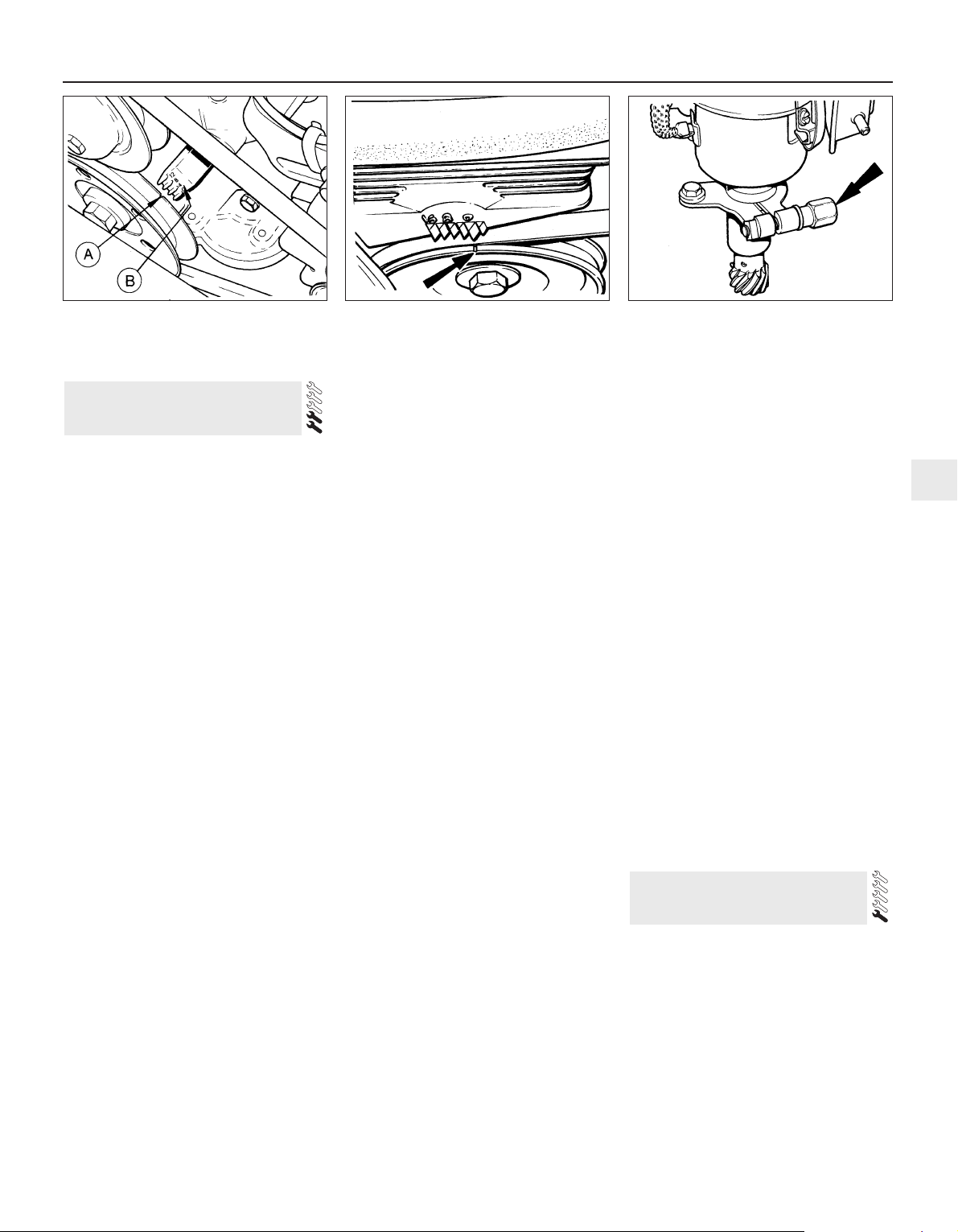
5 To adjust the points using feeler blades,
turn the crankshaft using a spanner on the
crankshaft pulley bolt until the heel of the
contact breaker arm is on the peak of one of
the four cam lobes and the points are fully
open. A feeler blade of thickness equal to the
contact breaker points gap as given in the
Specifications should now just slide between
the point faces (see illustrations).
6 If adjustment is required, slacken the
retaining screw slightly and move the fixed
point as necessary to achieve the desired gap
(see illustrations). After adjustment tighten
the retaining screw and recheck the gap.
7 Refit the rotor arm and the distributor cap.
8 If a dwell meter is available adjust the
contact breaker points by measuring and
setting the dwell angle as follows.
9 The dwell angle is the number of degrees of
distributor cam rotation during which the
contact breaker points are closed; ie the
period from when the points close after being
opened by one cam lobe, until they are
opened again by the next cam lobe. The
advantages of setting the points by this
method are that any wear of the distributor
shaft or cam lobes is taken into account and
the inaccuracies associated with using feeler
blades are eliminated. Also, on 1.1 litre CVH
engines the static ignition timing is accurately
set in production and adjustment of the
ignition timing in service has been deleted
from the maintenance schedule. Therefore
dwell angle adjustment is far more critical on
these engines.
10 In general a dwell meter should be used in
accordance with the manufacturer’s
instructions. However, the use of one type of
meter is outlined as follows.
11 Remove the distributor cap and rotor arm
and connect one lead of the dwell meter to
the “+” terminal on the coil and the other lead
to the coil “-” terminal.
12 Whilst an assistant turns on the ignition
and cranks the engine on the starter, observe
the reading on the dwell meter scale. With the
engine cranking the reading should be equal
to the dwell angle given in the Specifications.
13 If the dwell angle is too small, the contact
breaker points gap should be reduced and if
the dwell angle is excessive the gap should be
increased.
14 Adjust the points gap while the engine is
cranking using the method described in
paragraph 6. When the dwell angle is
satisfactory, disconnect the meter, then refit
the rotor arm and distributor cap.
15 Check the ignition timing (Section 14).
1•12 Every 6000 miles or 6 Months
13.5a Contact breaker points gap (A) - Bosch distributor
13.6a Contact breaker point components - Bosch distributor
A LT lead connector B Contact breaker retaining screw
13.6b Contact breaker point components - Lucas distributor
A Secondary movement cam and peg B Contact breaker retaining screw
13.5b Contact breaker points gap (A) - Lucas distributor
The points can be easily
moved by engaging a
screwdriver in the slot on the
end of the fixed point and
levering against the corresponding slot
or raised pips on the baseplate.
Note: With modern ignition systems the only
suitable way to time the ignition accurately is
with a stroboscopic timing light. However, for
initial setting up purposes (ie after major
overhaul, or if the timing has been otherwise
completely lost) a basic initial static setting
may be used to get the engine started Once
the engine is running, the timing should be
accurately set using the timing light. Before
carrying out any of the following, ensure that
the contact breaker points are correctly
adjusted as described in Section 13.
1 In order that the engine can run efficiently, it
is necessary for a spark to occur at the spark
plug and ignite the fuel/air mixture at the
instant just before the piston on the
compression stroke reaches the top of its
travel. The precise instant at which the spark
occurs is determined by the ignition timing
and this is quoted in degrees before top dead
centre (BTDC).
2 If the timing is being checked as a
maintenance or service procedure, refer to
paragraph 11 onwards. If the distributor has
been dismantled or renewed, or if its position
on the engine has been altered, obtain an
initial static setting as follows.
Static setting
3 Pull off the plug lead and remove No 1
spark plug (nearest the crankshaft pulley).
4 Place a finger over the plug hole and turn
the crankshaft in the normal direction of
rotation (clockwise from the crankshaft pulley
end) until pressure is felt in No 1 cylinder. This
indicates that the piston is commencing its
compression stroke. The crankshaft can be
turned with a spanner on the pulley bolt.
5 Continue turning the crankshaft until the
notch on the pulley is aligned with the
appropriate mark on the timing scale for the
engine being worked on (see Specifications).
On OHV engines the timing scale is cast into
the timing cover and situated just above and
to the right of the pulley. On CVH engines the
scale is moulded into the timing belt cover
and is situated directly above the pulley. On
all engines the “O” mark on the scale
represents Top Dead Centre (TDC) and the
raised projections to the left of TDC are in
increments of 4° BTDC (see illustrations).
6 Remove the distributor cap and check that
the rotor arm is pointing towards the No 1
spark plug lead segment in the cap.
7 Slacken the distributor clamp pinch bolt
(OHV engines) or the three distributor flange
securing bolts (CVH engines) (see
illustration).
8 Turn the distributor body anti-clockwise
slightly until the contact breaker points are
closed, then slowly turn the distributor body
clockwise until the points just open. Hold the
distributor body in this position and tighten
the clamp pinch bolt or flange securing bolts
as applicable.
9 Refit the distributor cap, No 1 spark plug
and the plug lead.
10 It should now be possible to start and run
the engine enabling the timing to be
accurately checked with a timing light as
follows.
Stroboscopic setting
11 Refer to the Specifications for the timing
setting applicable to the engine being worked
on and then highlight the appropriate mark on
the timing scale and the notch in the pulley
with a dab of white paint (see paragraph 5).
12 Connect a timing light to the engine in
accordance with the manufacturer’s
instructions (usually between No 1 spark plug
and plug lead).
13 Disconnect the vacuum hose at the
distributor vacuum unit and plug the hose.
14 Start the engine and allow it to idle.
15 Point the timing light at the timing marks.
They should appear to be stationary with the
crankshaft pulley notch in alignment with the
appropriate notch on the scale.
16 If adjustment is necessary (ie the marks are
not aligned) slacken the distributor clamp pinch
bolt or flange securing bolts as applicable, and
turn the distributor body as necessary to align
the marks. Tighten the pinch bolt or flange
bolts when the setting is correct.
17 A secondary use of the timing light is to
check that the centrifugal and vacuum
advance functions of the distributor are
working.
18 The tests are not of course precise as
would be the case if sophisticated equipment
were used, but will at least indicate the
serviceability of the unit.
19 With the engine idling, timing light
connected and vacuum pipe disconnected
and plugged as described in the preceding
paragraphs, increase the engine speed to
2000 rpm and note the approximate distance
which the pulley mark moves out of alignment
with the mark on the scale.
20 Reconnect the vacuum pipe to the
distributor and repeat the test when for the
same increase in engine speed, the alignment
differential of the timing marks should be
greater than previously observed.
21 If the timing marks did not appear to move
during the first test, a fault in the distributor
centrifugal advance mechanism is indicated.
No increased movement of the marks during
the second test indicates a punctured
diaphragm in the vacuum unit, or a leak in the
vacuum line.
22 On completion of the adjustments and
checks, switch off the engine and disconnect
the timing light.
1 The correct functioning of the spark plugs is
vital for the correct running and efficiency of
the engine. It is essential that the plugs fitted
are appropriate for the engine, and the
suitable type is specified at the end of this
chapter. If this type is used and the engine is
in good condition, the spark plugs should not
need attention between scheduled
replacement intervals. Spark plug cleaning is
rarely necessary and should not be attempted
unless specialised equipment is available as
damage can easily be caused to the firing
ends.
15 Spark plug renewal -
RS Turbo models
14 Ignition timing check - models
with contact breaker distributor
Every 6000 miles or 6 Months 1•13
1
14.5b Crankshaft pulley notch (arrowed)
and timing scale - CVH engine
14.7 Distributor clamp pinch-bolt location
(arrowed) - OHV engines
14.5a Timing mark identification OHV engines
A Notch on crankshaft pulley
B Timing scale cast into timing cover
2 To remove the plugs, first mark the HT
leads to ensure correct refitment, then pull
them off the plugs. When removing the leads,
pull the terminal insulator at the end of the
lead - not the lead itself.
3 Using a spark plug spanner or deep socket
and extension bar, unscrew the plugs and
remove them from the engine (see
illustration).
4 The condition of the spark plugs will also
tell much about the condition of the engine.
5 If the insulator nose of the spark plug is
clean and white, with no deposits, this is
indicative of a weak mixture, or too hot a plug.
(A hot plug transfers heat away from the
electrode slowly - a cold plug transfers it away
quickly.)
6 If the tip and insulator nose are covered
with hard black-looking deposits, then this is
indicative that the mixture is too rich. Should
the plug be black and oily, then it is likely that
the engine is fairly worn, as well as the mixture
being too rich.
7 If the insulator nose is covered with light tan
to greyish brown deposits, then the mixture is
correct and it is likely that the engine is in
good condition.
8 The spark plug gap is of considerable
importance, as if it is too large or too small,
the size of the spark and its efficiency will be
seriously impaired. The spark plug gap should
be set to the figure given in the Specifications
at the beginning of this Chapter.
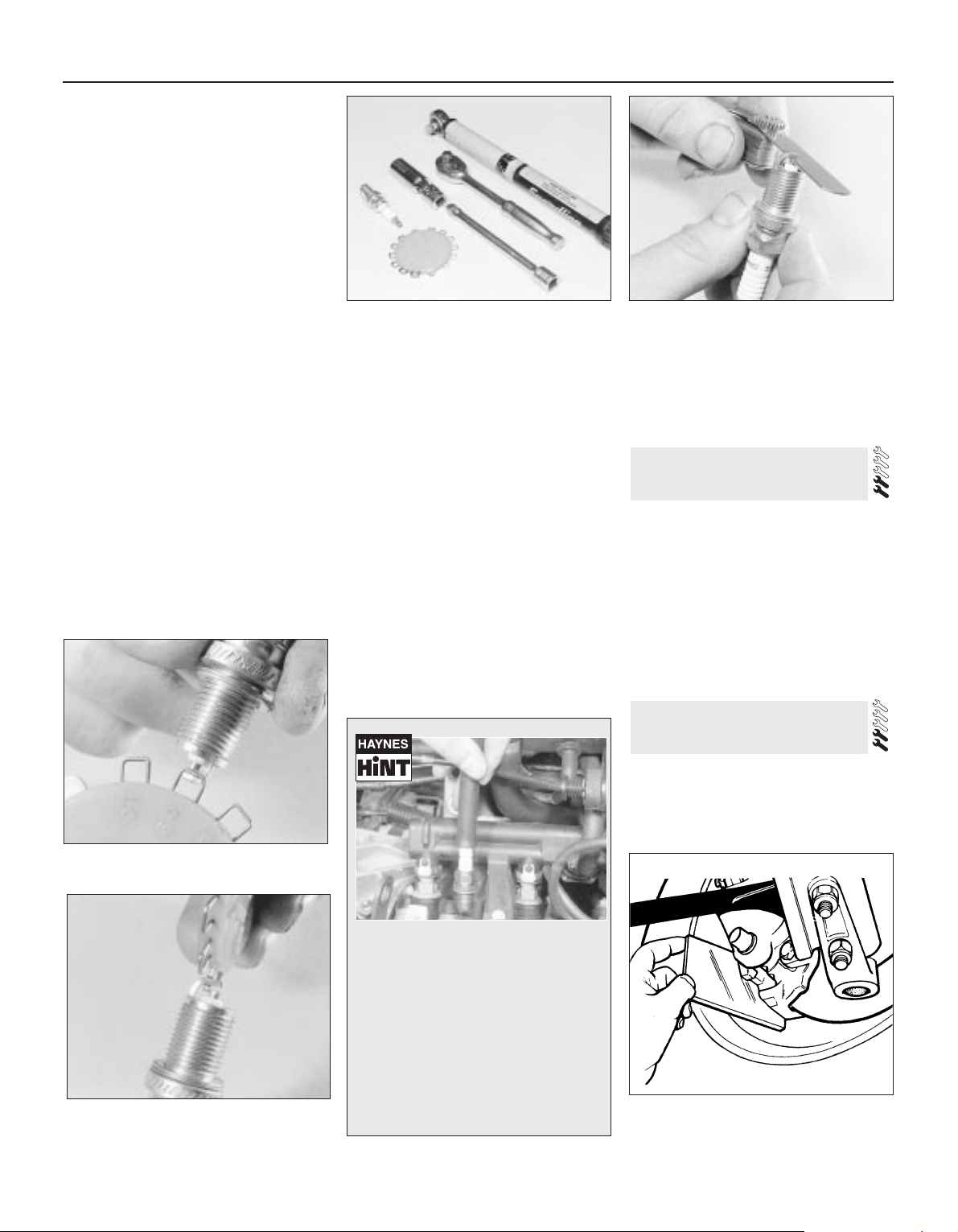
9 To set it, measure the gap with a feeler
blade, and then bend open, or close, the outer
plug electrode until the correct gap is
achieved (see illustration). The centre
electrode should never be bent as this may
crack the insulation and cause plug failure, if
nothing worse.
10 Special spark plug electrode cap
adjusting tools are available from most motor
accessory shops (see illustrations).
11 Before fitting the plugs first ensure that the
plug threads and the seating area in the
cylinder head are clean, dry and free of carbon.
12 Screw the plugs in by hand initially and
then fully tighten to the specified torque. If a
torque wrench is not available, tighten the
plugs until initial resistance is felt, then tighten
by a further
1
⁄16 of a turn for the taper seat plugs
fitted to OHV engines, or
1
⁄4 of a turn for the
gasket seat type fitted to CVH engines. Do not
over-tighten the spark plugs, otherwise
damage to the threads may occur and they
will also be extremely difficult to remove in the
future.
13 Refit the plug leads in the correct order
ensuring that they are a secure fit over the
plug ends. Periodically wipe the leads clean to
reduce the risk of HT leakage by arcing and
remove any traces of corrosion that may
occur on the end fittings.
1 Place a mirror between the roadwheel and
the caliper and check the thickness of the
friction material of the disc pads (see
illustration). If the material has worn down to
the specified minimum or less, the pads must
be renewed as an axle set (four pads).
2 For a comprehensive check, the brake
pads should be removed and cleaned. This
will permit the operation of the caliper to be
checked, and the condition of the brake disc
itself to be examined on both sides. Refer to
Chapter 9 for further information.
1 Due to the fact that the rear brake drums
are combined with the hubs, which makes
removal of the drums more complicated than
is the case with detachable drums, inspection
of the shoe linings can be carried out at the
17 Rear brake shoe lining check
16 Front brake disc pad check
1•14 Every 6000 miles or 6 Months
15.9 Measuring the spark plug gap with a
feeler blade
15.10a Measuring the spark plug gap with
a wire gauge . . .
16.1 Checking the front disc pad wear
using a mirror
15.10b . . . and adjusting the gap using a
special adjusting tool
15.3 Tools required for spark plug
removal, gap adjustment and refitting
It is very often difficult to insert spark
plugs into their holes without crossthreading them. To avoid this
possibility, fit a short length of 5/16inch internal diameter rubber hose
over the end of the spark plug. The
flexible hose acts as a universal joint
to help align the plug with the plug
hole. Should the plug begin to crossthread, the hose will slip on the spark
plug, preventing thread damage to the
aluminium cylinder head.
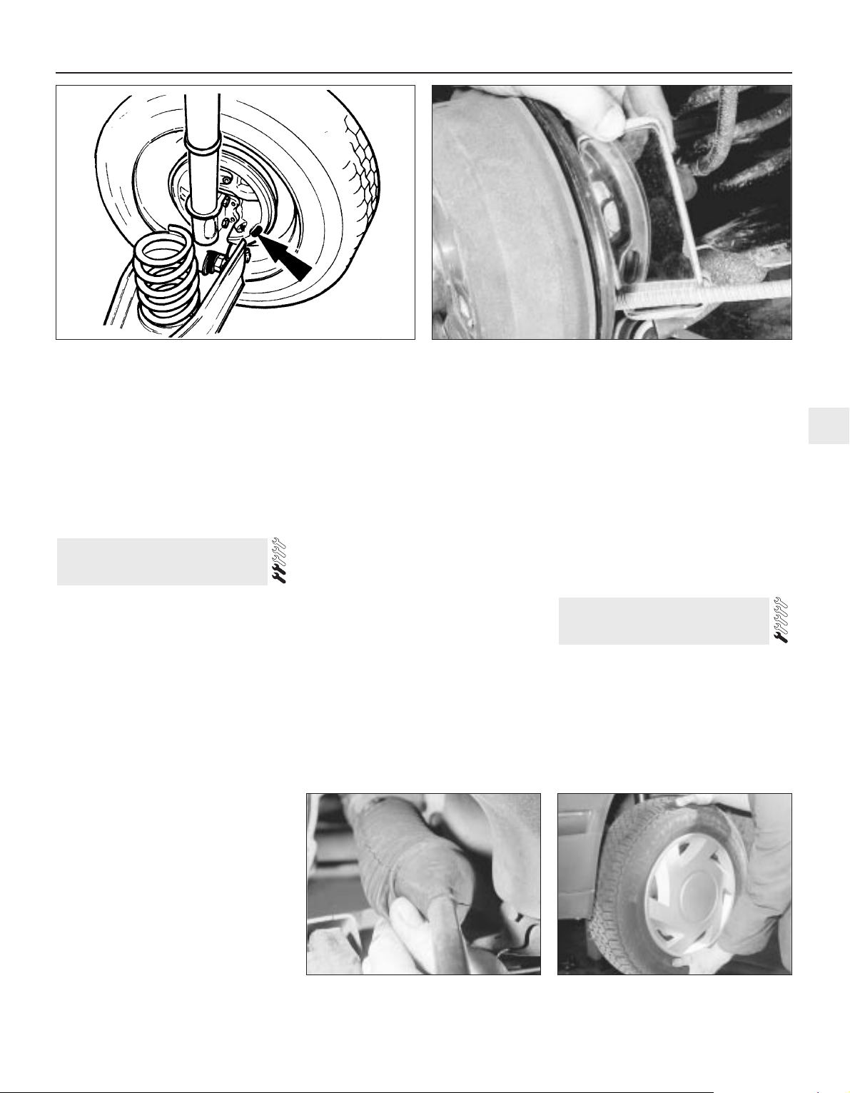
specified intervals by prising out the small
inspection plug from the brake backplate and
observing the linings through the hole using a
mirror (see illustrations).
2 A minimum thickness of friction material
must always be observed on the shoes. If it is
worn down to this level, renew the shoes.
3 Do not attempt to re-line shoes yourself but
always obtain factory re-lined shoes.
4 Renew the shoes in an axle set (four shoes),
even if only one is worn to the minimum.
Front suspension and steering
check
1 Raise the front of the vehicle, and securely
support it on axle stands (see “Jacking and
Vehicle Support”).
2 Visually inspect the balljoint dust covers
and the steering rack-and-pinion gaiters for
splits, chafing or deterioration (see
illustration). Any wear of these components
will cause loss of lubricant, together with dirt
and water entry, resulting in rapid
deterioration of the balljoints or steering gear.
3 Grasp the roadwheel at the 12 o’clock and
6 o’clock positions, and try to rock it (see
illustration). Very slight free play may be felt,
but if the movement is appreciable, further
investigation is necessary to determine the
source. Continue rocking the wheel while an
assistant depresses the footbrake. If the
movement is now eliminated or significantly
reduced, it is likely that the hub bearings are
at fault. If the free play is still evident with the
footbrake depressed, then there is wear in the
suspension joints or mountings.
4 Now grasp the wheel at the 9 o’clock and 3
o’clock positions, and try to rock it as before.
Any movement felt now may again be caused
by wear in the hub bearings or the steering
track-rod balljoints. If the inner or outer balljoint
is worn, the visual movement will be obvious.
5 Using a large screwdriver or flat bar, check
for wear in the suspension mounting bushes
by levering between the relevant suspension
component and its attachment point. Some
movement is to be expected as the mountings
are made of rubber, but excessive wear
should be obvious. Also check the condition
of any visible rubber bushes, looking for splits,
cracks or contamination of the rubber.
6 With the car standing on its wheels, have an
assistant turn the steering wheel back and
forth about an eighth of a turn each way.
There should be very little, if any, lost
movement between the steering wheel and
roadwheels. If this is not the case, closely
observe the joints and mountings previously
described, but in addition, check the steering
column universal joints for wear, and the rackand-pinion steering gear itself.
7 Visually check that each lower arm balljoint
is correctly located in the hub carrier, ensuring
that the Torx type pinch-bolt is fully engaged
in the groove in the balljoint stud.
Suspension strut/shock absorber
check
8 Check for any signs of fluid leakage around
the suspension strut/shock absorber body, or
from the rubber gaiter around the piston rod.
Should any fluid be noticed, the suspension
strut/shock absorber is defective internally,
and should be renewed. Note: Suspension
struts/shock absorbers should always be
renewed in pairs on the same axle.
9 The efficiency of the suspension
strut/shock absorber may be checked by
bouncing the vehicle at each corner.
Generally speaking, the body will return to its
normal position and stop after being
depressed. If it rises and returns on a
rebound, the suspension strut/shock
absorber is probably suspect. Examine also
the suspension strut/shock absorber upper
and lower mountings for any signs of wear.
1 Periodically check the belts for fraying or
other damage. If evident, renew the belt.
2 If the belts become dirty, wipe them with a
damp cloth using a little detergent only.
3 Check the tightness of the anchor bolts and
if they are ever disconnected, make quite sure
that the original sequence of fitting of
washers, bushes and anchor plates is
retained.
19 Seat belt check
18 Suspension and steering
check
Every 6000 miles or 6 Months 1•15
1
17.1a Brake shoe viewing hole location (arrowed) in backplate 17.1b Checking rear brake lining wear with a mirror
18.3 Rocking the roadwheel to check
steering/suspension components
18.2 Checking a steering gear gaiter
1 A conventional vee drivebelt is used to
drive both the alternators and water pump
pulleys on OHV and HCS engines, and the
alternator pulley only on CVH engines, power
being transmitted via a pulley on the engine
crankshaft.
2 To remove the drivebelt, slacken the
alternator mounting bolts and the bolts on the
adjuster link and push the alternator in
towards the engine as far as possible (see
illustration).
3 Withdraw the belt from the pulleys. In some
instances it may also be necessary to remove
the adjuster link-to-alternator bolt to avoid
straining the drivebelt.
4 Fit the belt by slipping it over the pulley
rims. If necessary remove the adjuster link-toalternator bolt, if not already done, to avoid
straining the belt. Never be tempted to
remove or refit the drivebelt by prising it over
a pulley rim otherwise the pulley or the
drivebelt internal webbing will be damaged.
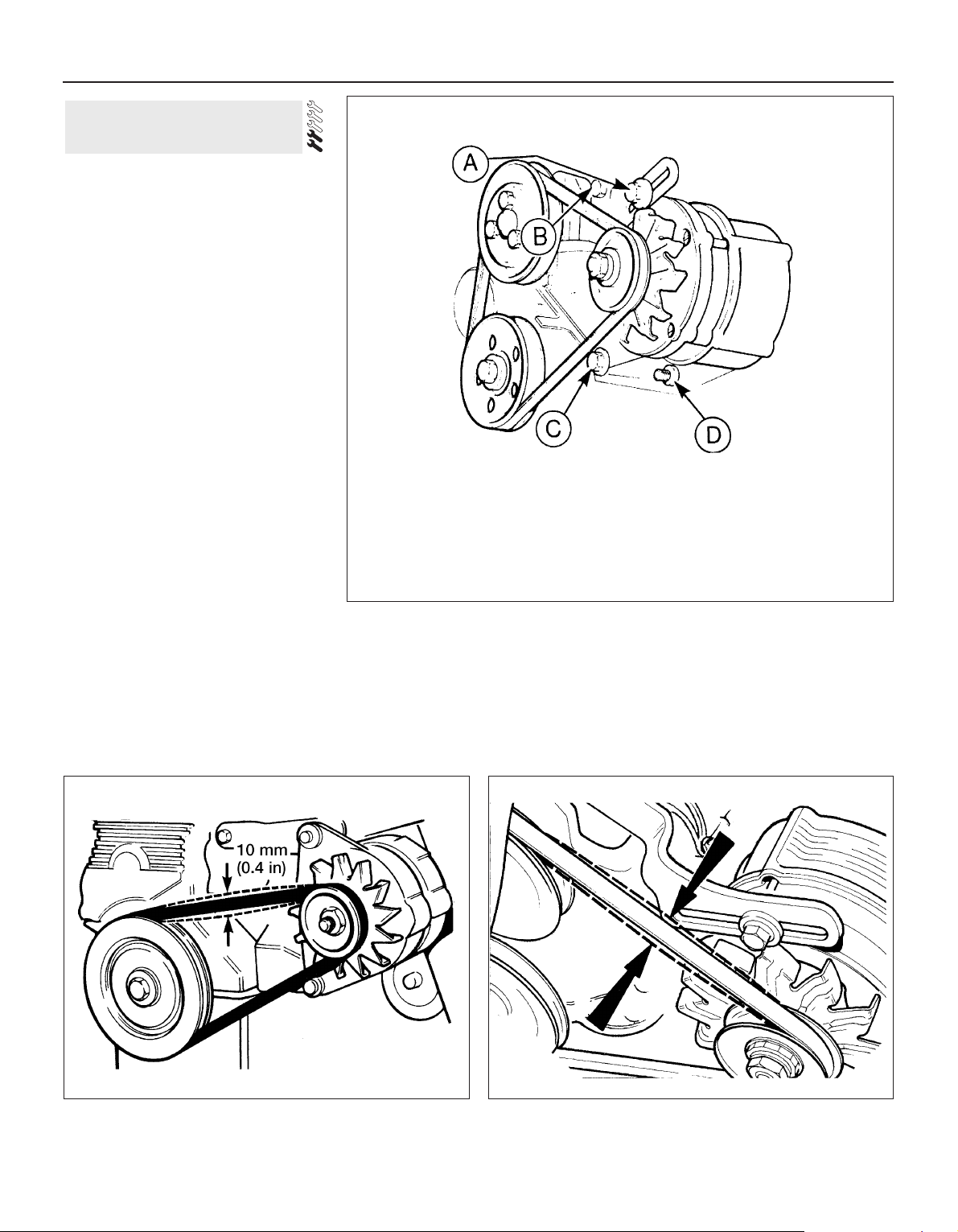
5 To tension the belt pull the alternator away
from the engine until the belt is fairly taut, and
tighten the adjuster link-to-alternator bolt.
Check that the total deflection of the belt,
using finger pressure at a point midway
between the alternator and crankshaft or
water pump pulleys, is 10 mm (0.4 in) (see
illustrations). A little trial and error may be
necessary to obtain the correct tension. If the
belt is too slack, it will slip in the pulleys and
soon become glazed or burnt. This is often
indicated by a screeching noise as the engine
is accelerated, particularly when the
headlights or other electrical accessories are
switched on. If the belt is too tight the
bearings in the water pump and/or alternator
will soon be damaged.
6 Once the tension is correct, tighten the
remaining adjuster link bolt, front mounting
bolt and rear mounting bolt in that order.
7 If a new belt has been fitted the tension
should be rechecked and adjusted again if
necessary after the engine has run for
approximately ten minutes.
20 Alternator drivebelt check
1•16 Every 6000 miles or 6 Months
20.5a Drivebelt tension checking point - CVH engines 20.5b Drivebelt tension checking point - OHV engines
20.2 Alternator mounting and adjuster link bolts
A Adjuster link-to-alternator bolt
B Adjuster link-to-engine bolt
C and D Alternator mounting bolts

Maintenance procedures 1•17
1
OHV engines
1 This operation should be carried out with
the engine cold and the air cleaner and rocker
cover removed.
2 Using a ring spanner or socket on the
crankshaft pulley bolt, turn the crankshaft in a
clockwise direction until No 1 piston is at TDC
on its compression stroke. This can be
verified by checking that the pulley and timing
cover marks are in alignment and that the
valves of No 4 cylinder are rocking. When the
valves are rocking, this means that the
slightest rotation of the crankshaft pulley in
either direction will cause one rocker arm to
move up and the other to move down.
3 Numbering from the thermostat housing
end of the cylinder head, the valves are
identified as follows.
Valve No Cylinder No
1 Exhaust 1
2 Inlet 1
3 Exhaust 2
4 Inlet 2
5 Exhaust 3
6 Inlet 3
7 Exhaust 4
8 Inlet 4
4 Adjust the valve clearances by following the
sequence given in the following table. Turn
the crankshaft pulley 180º (half a turn) after
adjusting each pair:
Valves rocking Valves to adjust
7 and 8 1 (Exhaust), 2 (Inlet)
5 and 6 3 (Exhaust), 4 (Inlet)
1 and 2 7 (Exhaust), 8 (Inlet)
3 and 4 5 (Exhaust), 6 (Inlet)
5 The clearances for the inlet and exhaust
valves are different (see Specifications). Use a
feeler blade of the appropriate thickness to
check each clearance between the end of the
valve stem and the rocker arm. The gauge
should be a stiff sliding fit. If it is not, turn the
adjuster bolt with a ring spanner. These bolts
are of stiff thread type and require no locking
nut. Turn the bolt clockwise to reduce the
clearance and anti-clockwise to increase it
(see illustration).
6 Refit the air cleaner and rocker cover on
completion of adjustment.
HCS engines
7 The procedure is as described previously
for OHV engines, but note that the valve
arrangement has been altered and is now as
shown below. Take care not to overtighten the
rocker cover bolts on refitting, as this can
result in leaks.
Valve No Cylinder No
1 Exhaust 1
2 Inlet 1
3 Exhaust 2
4 Inlet 2
5 Inlet 3
6 Exhaust 3
7 Inlet 4
8 Exhaust 4
With the vehicle raised on a hoist or
supported on axle stands (see “Jacking and
Vehicle Support”), check the exhaust system
for signs of leaks, corrosion or damage and
check the rubber mountings for condition and
security (see illustration). Where damage or
corrosion are evident, renew the system
complete or in sections, as applicable, using
the information given in Chapter 4, Part E.
Check the tightness of the turbocharger-toexhaust manifold securing nuts using a torque
wrench.
The procedure is as described for RS Turbo
models in Section 15.
1 Spring back the retaining clips or undo the
screws as appropriate and lift off the
distributor cap.
2 Withdraw the rotor arm from the distributor
shaft.
3 On the Bosch distributor disconnect the
contact breaker points LT lead at the spade
connector. On the Lucas distributor ease the
contact breaker spring arm out of the plastic
insulator and slide the combined LT and
condenser lead out of the hooked end of the
spring arm.
4 Undo the retaining screw and withdraw the
contact breaker points from the distributor
baseplate. Take care not to drop the screw
and washer inside the distributor during
removal and refitting. If possible use a
magnetic screwdriver, or alternatively, retain
the screw on the end of the screwdriver using
a dab of grease.
5 Wipe clean the distributor cam, then apply
a trace of high-melting-point grease to the
four cam lobes. Also, on OHV engines apply
two drops of light oil to the felt pad at the top
of the distributor shaft.
25 Contact breaker points
renewal
24 Spark plug renewal
23 Turbocharger-to-manifold
nut check - RS Turbo models
22 Exhaust system check
21 Valve clearance adjustment -
OHV and HCS engines
21.5 Valve clearance adjustment 22.1 Exhaust silencer mounting
Every 12 000 miles or 12 months
6 Locate the new contact breaker points on
the baseplate and secure with the retaining
screw, lightly tightened only at this stage. On
the Lucas distributor ensure that the
secondary movement cam is engaged with
the peg, and that both washers are refitted
with the retaining screw (see illustration
13.6b).
7 Reconnect the LT lead, then refer to
Section 13 and adjust the contact breaker
points gap.
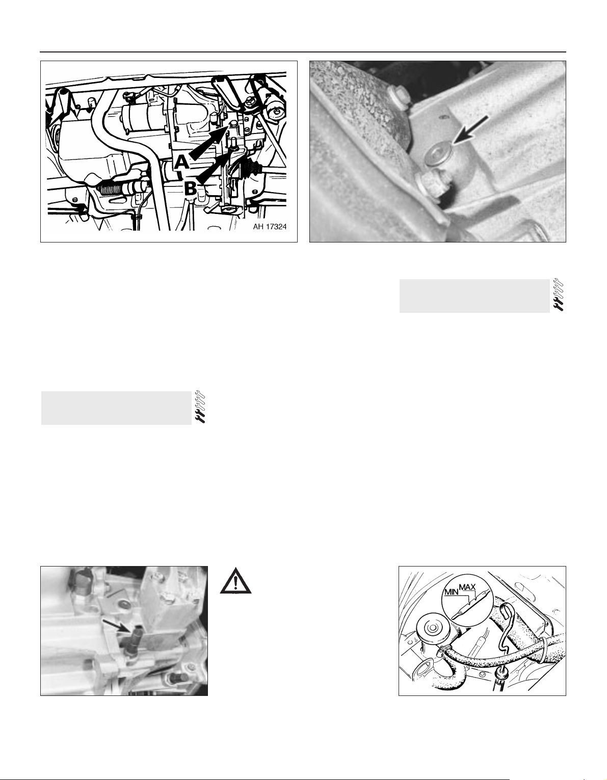
1 With the car on level ground wipe the area
around the filler plug, then unscrew the plug
using a socket spanner, or on later versions a
suitable Torx or Allen key or socket bit, as
applicable. Access can be gained from above
or below the car (see illustrations).
2 Locate the aluminium build code tag, which
is secured to one of the transmission housing
upper bolts, and note the transmission part
number stamped on the tag. If the last letter of
the part number suffix is a D then the
transmission was manufactured prior to
August 1985. Transmissions manufactured
from August 1985 have an E as the last letter
of the part number suffix.
3 On the early type transmission (suffix letter
D) the oil level must be maintained between 5
and 10 mm (0.2 and 0.4 in) below the lower
edge of the filler plug hole.
4 If the transmission is of the later type (suffix
letter E) the oil level must be maintained
between 0 and 5 mm (0.2 in) below the lower
edge of the filler plug hole.
5 To simplify the checking procedure a
dipstick can be made from thin rod bent at
right angles and having marks on one “leg”
made with a file at 5 mm (0.2 in) intervals. Rest
the unmarked leg on the lower edge of the
filler plug hole with the marked leg immersed
in the oil. Remove the dipstick, read off the
level and top-up if necessary using the
specified grade of oil. Refit the filler plug on
completion.
6 Renewal of the transmission oil is not a
service requirement, but if draining is
necessary prior to a repair or overhaul task
place a suitable container beneath the
selector shaft locking mechanism cap nut
located just below the filler plug (see
illustration). Unscrew the cap nut, remove
the spring and interlock pin and allow the oil
to drain.
1 The automatic transmission fluid level must
be checked when the engine and
transmission are at normal operating
temperature; preferably after a short journey.
2 Park the car on level ground, then fully
apply the handbrake.
3 With the engine running at its normal idle
speed, apply the footbrake and simultaneously
move the selector lever through the full range
of positions three times then move it back to
the P position. Allow the engine to run at idle
for a further period of one minute.
4 With the engine still idling, extract the
transmission fluid level dipstick and wipe it
dry, with a clean non-fluffy cloth. Fully reinsert
the dipstick and then extract it again and
check the fluid level mark, which must be
between the “MAX” and “MIN” markings (see
illustration)
5 If topping-up is necessary, use only the
specified fluid type and pour it through the
dipstick tube, but take care not to overfill. The
level must not exceed the “MAX” mark.
27 Automatic transmission fluid
level check
26 Manual transmission oil level
check
1•18 Every 12 000 miles or 12 Months
26.6 Selector shaft locking mechanism
cap nut (arrowed)
26.1a Transmission oil filler plug (A) and selector shaft locking
mechanism cap (B)
26.1b Allen type transmission filler plug (arrowed) as fitted to
later models
27.4 Transmission fluid level dipstick
location and level markings
Caution: Take care when
unscrewing the cap nut as the
tension of the spring may cause
the pin to fly out as the cap nut
is released. Refit the pin, spring and cap
nut when draining is complete, but apply
sealer to the cap nut threads (see
Specifications). Note that from 1986
onwards the cap nut is shrouded by the
transmission support crossmember and
cannot be removed in situ. On these
models draining can only be carried out
after removal of the transmission from
the car.

Every 12 000 miles or 12 Months 1•19
1
6 An improved type of transmission fluid is
used in later models and before topping-up or
refilling it is necessary to identify the
transmission being worked on so that the
correct fluid may be obtained.
7 Locate the transmission identification
number which is stamped on a metal tag
attached to the top of the valve body cover
(see illustration). If, at the end of the second
line on the metal tag, the prefix E3RPappears, then the transmission is of the early
type. If the prefix is E6RP- then the unit is of
the later type. Later transmissions can also be
identified by having a black dipstick stating
the fluid specification and type. Having
determined whether the transmission is of the
early or later type, refer to “Lubricants and
fluids” for the fluid requirement. Under no
circumstances may the later type fluid be used
in the early type transmission, and vice versa.
8 If the fluid level was below the minimum
mark when checked or is in constant need of
topping-up, check around the transmission
for any signs of excessive fluid leaks, and if
present then they must be rectified without
delay.
9 If the colour of the fluid is dark brown or
black this denotes the sign of a worn brake
band or transmission clutches in which case
have your Ford dealer check the transmission
at the earliest opportunity.
Carry out a thorough road test, ensuring
that all gearchanges occur smoothly without
snatching, and without an increase in engine
speed between changes. Check that all gear
positions can be engaged with the
appropriate movement of the selector lever,
and with the vehicle at rest. Check the
operation of the parking pawl when “P” is
selected.
1 Carry out a thorough inspection of the
driveshafts and joints as follows.
2 Jack up the front of the car and support it
securely on axle stands (see “Jacking and
Vehicle Support”).
3 Slowly rotate the roadwheel and inspect the
condition of the outer joint rubber bellows.
Check for signs of cracking, splits or
deterioration of the rubber which may allow
the grease to escape and lead to water and
grit entry into the joint (see illustration). Also
check the security and condition of the
retaining clips. Repeat these checks on the
inner constant velocity joints. If any damage
or deterioration is found, the bellows should
be renewed as described in Chapter 8.
4 Continue rotating the roadwheel and check
for any distortion or damage to the driveshaft.
Check for any free play in the joints by first
holding the driveshaft and attempting to
rotate the wheel. Repeat this check by holding
the inner joint and attempting to rotate the
driveshaft. Any appreciable movement
indicates wear in the joints, wear in the
driveshaft splines or loose retaining nut.
5 Road test the car and listen for a metallic
clicking from the front as the car is driven
slowly in a circle with the steering on full lock.
If a clicking noise is heard this indicates wear
in the outer constant velocity joint caused by
excessive clearance between the balls in the
joint and the recesses in which they operate.
Remove and inspect the joint (Chapter 8).
6 If vibration, consistent with road speed, is
felt through the car when accelerating, there is
a possibility of wear in the inner constant
velocity joint. If so, renewal of the driveshaft
inner joint will be necessary.
Check the wheel rims for distortion,
damage and excessive run-out. Also make
sure that the balance weights are secure with
no obvious signs that any are missing.
Check the torque of the wheel bolts.
1 Work around the vehicle, and lubricate the
bonnet, door and tailgate hinges with a light
machine oil such as Duckhams Home Oil.
2 Lightly lubricate the bonnet release
mechanism and exposed sections of inner
cable with a smear of grease.
3 Check the security and operation of all
hinges, latches and locks, adjusting them
where required. Where applicable, check the
operation of the central locking system.
4 Check the condition and operation of the
tailgate struts, renewing them if either is
leaking or is no longer able to support the
tailgate securely when raised.
Instruments and electrical
equipment
1 Check the operation of all instruments and
electrical equipment.
2 Make sure that all instruments read
correctly, and switch on all electrical
equipment in turn to check that it functions
properly.
Steering and suspension
3 Check for any abnormalities in the steering,
suspension, handling or road “feel”.
4 Drive the vehicle, and check that there are
no unusual vibrations or noises.
5 Check that the steering feels positive, with
no excessive “sloppiness”, or roughness, and
check for any suspension noises when
cornering, or when driving over bumps.
Drivetrain
6 Check the performance of the engine,
clutch, transmission and driveshafts.
7 Listen for any unusual noises from the
engine, clutch and transmission.
8 Make sure that the engine runs smoothly
when idling, and that there is no hesitation
when accelerating.
9 Where applicable, check that the clutch
action is smooth and progressive, that the
drive is taken up smoothly, and that the pedal
travel is not excessive. Also listen for any
noises when the clutch pedal is depressed.
10 Check that all gears can be engaged
smoothly, without noise, and that the gear
lever action is not abnormally vague or
“notchy”.
11 Listen for a metallic clicking sound from
the front of the vehicle, as the vehicle is driven
slowly in a circle with the steering on full lock.
32 Road test
31 Hinge and lock check and
lubrication
30 Roadwheel check
29 Driveshaft check
28 Automatic transmission
selector mechanism check
29.3 Checking driveshaft outer joint
rubber bellows
27.7 Transmission identification number on valve body tag
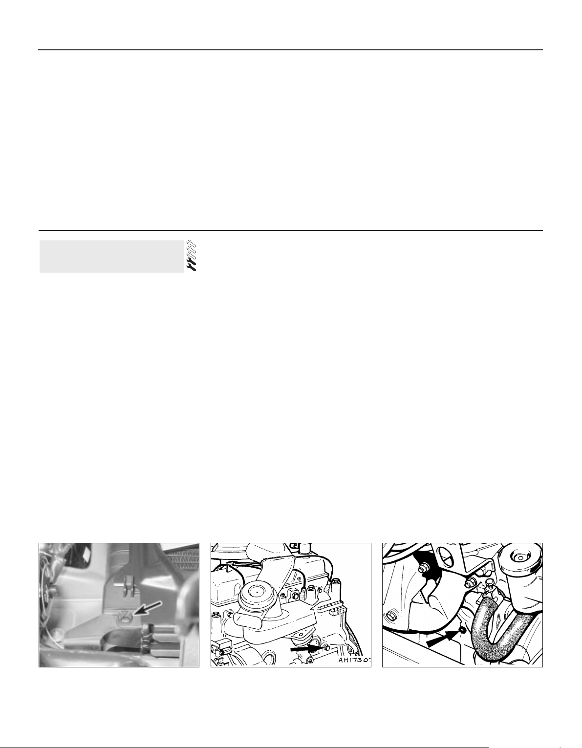
1•20 Every 12 000 miles or 12 Months
Carry out this check in both directions. If a
clicking noise is heard, this indicates wear in a
driveshaft joint, in which case, the complete
driveshaft must be renewed (see Chapter 8).
Check the operation and
performance of the braking
system
12 Make sure that the vehicle does not pull to
one side when braking, and that the wheels
do not lock prematurely when braking hard.
13 Check that there is no vibration through
the steering when braking.
14 Check that the handbrake operates
correctly, without excessive movement of the
lever, and that it holds the vehicle stationary
on a slope.
15 Test the operation of the brake servo unit
as follows. With the engine off, depress the
footbrake four or five times to exhaust the
vacuum. Start the engine, holding the brake
pedal depressed. As the engine starts, there
should be a noticeable “give” in the brake
pedal as vacuum builds up. Allow the engine
to run for at least two minutes, and then
switch it off. If the brake pedal is depressed
now, it should be possible to detect a hiss
from the servo as the pedal is depressed.
After about four or five applications, no further
hissing should be heard, and the pedal should
feel considerably firmer.
Cooling system draining
1 It is preferable to drain the system when the
coolant is cold. If it must be drained when hot,
release the pressure cap on the thermostat
housing (or expansion tank on later models)
very slowly, having first covered it with a cloth
to avoid any possibility of scalding. Having
relieved the pressure, remove the cap.
2 Set the heater control to the maximum heat
position.
3 Check to see if a drain plug is fitted to the
lower left-hand side of the radiator. If so,
place a suitable container beneath the
radiator, unscrew the plug and allow the
coolant to drain (see illustration).
4 If a drain plug is not fitted, place the
container beneath the radiator bottom hose.
Slacken the clip, release the hose and allow
the coolant to drain.
5 A cylinder block drain plug is also fitted to
certain models on the forward facing side of
the cylinder block, towards the flywheel end.
Where this is the case, unscrew the plug and
allow the cylinder block to drain into the
container (see illustrations).
Cooling system flushing
6 Providing that the correct mixture of
antifreeze and water has previously been
maintained in the system, then no flushing
should be necessary and the system can be
refilled immediately as described in the
following paragraphs.
7 Where the system has been neglected
however, and rust or sludge is evident at
draining, then the system should be flushed
through using a cold water hose inserted into
the thermostat housing (thermostat removed see Chapter 3). Continue flushing until the
water flows clean from the disconnected
bottom hose, radiator drain plug and cylinder
block drain plug, as applicable. If, after a
reasonable period the water still does not run
clear, the radiator can be flushed with a good
proprietary cleaning system.
8 If the radiator is suspected of being
clogged, remove and reverse flush it as
described in Chapter 3.
9 When the coolant is being changed, it is
recommended that the overflow pipe is
disconnected from the expansion tank and
the coolant drained from the tank. If the
interior of the tank is dirty, remove it and
thoroughly clean it out.
10 After draining or flushing, reconnect all
disconnected hoses and refit the drain plugs
where applicable.
Cooling system filling
11 Using the correct antifreeze mixture (See
following sub-Section) fill the system through
the thermostat housing filler neck slowly until
the coolant is nearly overflowing. Wait a few
moments for trapped air to escape and add
more coolant. Repeat until the level does not
drop and refit the cap. Pour similar strength
coolant into the expansion tank up to the
“MAX” mark and fit the cap.
12 On later models with a screw type pressure
cap on the expansion tank, fill the system in the
same way, but through the expansion tank
rather than the thermostat housing.
13 On all models start the engine and run it to
normal operating temperature then switch off.
Once it has cooled, check and carry out any
final topping-up to the expansion tank only.
Antifreeze mixture
14 Never operate the vehicle with plain water
in the cooling system. Apart from the danger
of freezing during winter conditions, an
important secondary purpose of antifreeze is
to inhibit the formation of rust and to reduce
corrosion.
15 The coolant must be renewed at the
intervals specified. Although the antifreeze
properties of the coolant will remain
indefinitely, the effectiveness of the rust and
corrosion inhibitors will gradually weaken.
33 Coolant renewal
33.3 Radiator drain plug location
(arrowed)
33.5a Cylinder block drain plug location
(arrowed) - OHV engines
33.5b Cylinder block drain plug location
(arrowed) - CVH engines
Every 24 000 miles or 2 years
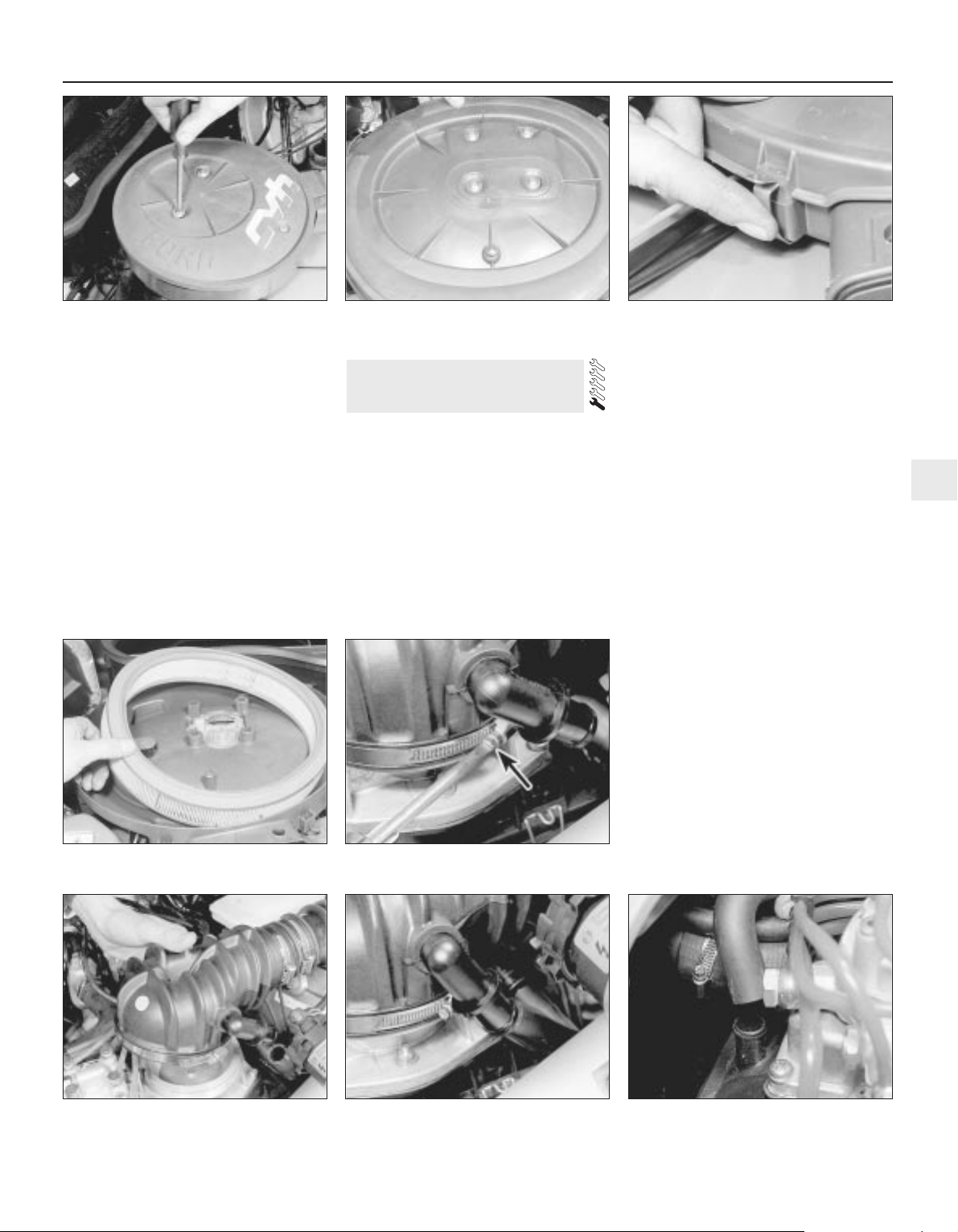
Every 24 000 miles or 2 Years 1•21
1
16 It is recommended that Ford Super Plus
antifreeze is used for filling and topping-up, as
it has been specially formulated for use in
Ford mixed metal engines (see “Lubricants
and fluids”).
17 A solution of 45% antifreeze must be
maintained in the system all year round which
will provide adequate protection against frost,
rust and corrosion.
18 After filling with antifreeze, a label should
be attached to the radiator stating the type of
antifreeze and the date installed. Any
subsequent topping-up should be made with
the same type and concentration of antifreeze.
19 Do not use engine antifreeze in the screen
washer system, as it will cause damage to the
vehicle paintwork. Screen wash antifreeze is
available from most motor accessory shops.
Carburettor and Central Fuel
Injection (CFI) models
1 To remove the air cleaner lid undo and
remove the retaining screws or bolts on the
top face of the lid (see illustrations).
2 Where applicable release the lid retaining
clips around the side of the air cleaner body
(see illustration).
3 Lift off the lid, remove and discard the
paper element and wipe out the inside of the
air cleaner body and lid (see illustration).
4 Place a new element in position and refit
the lid.
Bosch K-Jetronic fuel injection
models
5 Disconnect the battery earth lead.
6 Unscrew and loosen off the air ducting-to-
sensor plate unit securing band, then
separate the two (see illustrations).
7 Carefully pull free the shut-off valve hose
from the air ducting connector. The hose is a
press fit (see illustration).
8 Unscrew and remove the six air sensor
plate-to-cleaner top cover retaining screws,
but leave the plate unit in position.
9 Prise free and release the air cleaner cover
retaining clips and detach the hose from the
cover at the front (see illustration).
10 Carefully lift the sensor plate clear,
together with its gasket, and pivot it back out
of the way. Withdraw the shut-off valve from
the rear end of the cleaner case cover, then lift
out the cover and remove the element from
the casing (see illustrations).
11 If the air cleaner casing is to be removed
you will need to detach the fuel filter from the
side of the cleaner casing (leave the fuel lines
attached to the filter) and the air inlet hose
from the front end of the case. Unscrew and
remove the casing retaining nuts from the
inner wing panel and lift out the casing.
12 Refitting is the reversal of the removal
procedure. Wipe the casing clean before
inserting the new element. When fitting the
34 Air cleaner element renewal
34.1a Removing the air cleaner retaining
screws on a 1.3 litre CVH engine . . .
34.1b . . . and air cleaner retaining screw
locations on 1.4 litre CVH engine
34.2 Release the air cleaner lid retaining
clips, where fitted
34.6b . . . and lift the air duct away from
the sensor plate unit - K-Jetronic system
34. 3 Removing the air cleaner element 34.6a Slacken the securing band
screw . . .
34.7 Detach the shut-off valve hose K-Jetronic system
34.9 Detach the hose from the front of the
air cleaner cover - K-Jetronic system

sensor plate unit into position on the top
cover check that the gasket is in good
condition and aligned correctly (see
illustration).
13 Check that all connections are secure on
completion.
Bosch KE-Jetronic fuel injection
models
14 Undo the two bolts securing the air
cleaner assembly to the air sensor plate unit
and remove the air cleaner assembly (see
illustration).
15 Unclip the retaining clips and lift off the air
cleaner top cover. Remove the filter element
(see illustration).
16 Clean the inside of the air cleaner body
and fit a new filter element. Place the top
cover in position and secure with the clips.
17 Refit the unit to the air sensor plate and
secure with the two bolts.
Electronic Fuel Injection (EFI)
models
18 Proceed as described in paragraphs 15
and 16.
Carburettor and Central Fuel
Injection (CFI) engines
1 Where fitted, the crankcase ventilation filter
is located in the base of the air cleaner.
2 The filter can be renewed by pulling it out of
the air cleaner after disconnecting the hoses
(see illustration).
35 Crankcase emission control
filter renewal - CVH engines
1•22 Every 24 000 miles or 2 Years
34.10c . . . lift out the cover . . .
34.10a Lift the sensor plate clear . . . 34.10b . . . withdraw the shut-off valve . . .
34.14 KE-Jetronic air cleaner retaining
bolts (arrowed)
34.10d . . . and withdraw the element K-Jetronic system
34.15 Lift off the air cleaner and remove
the element - KE-Jetronic system
35.2 Crankcase ventilation filter renewal
on CVH engines with carburettor
34.12 Locating the sensor unit gasket
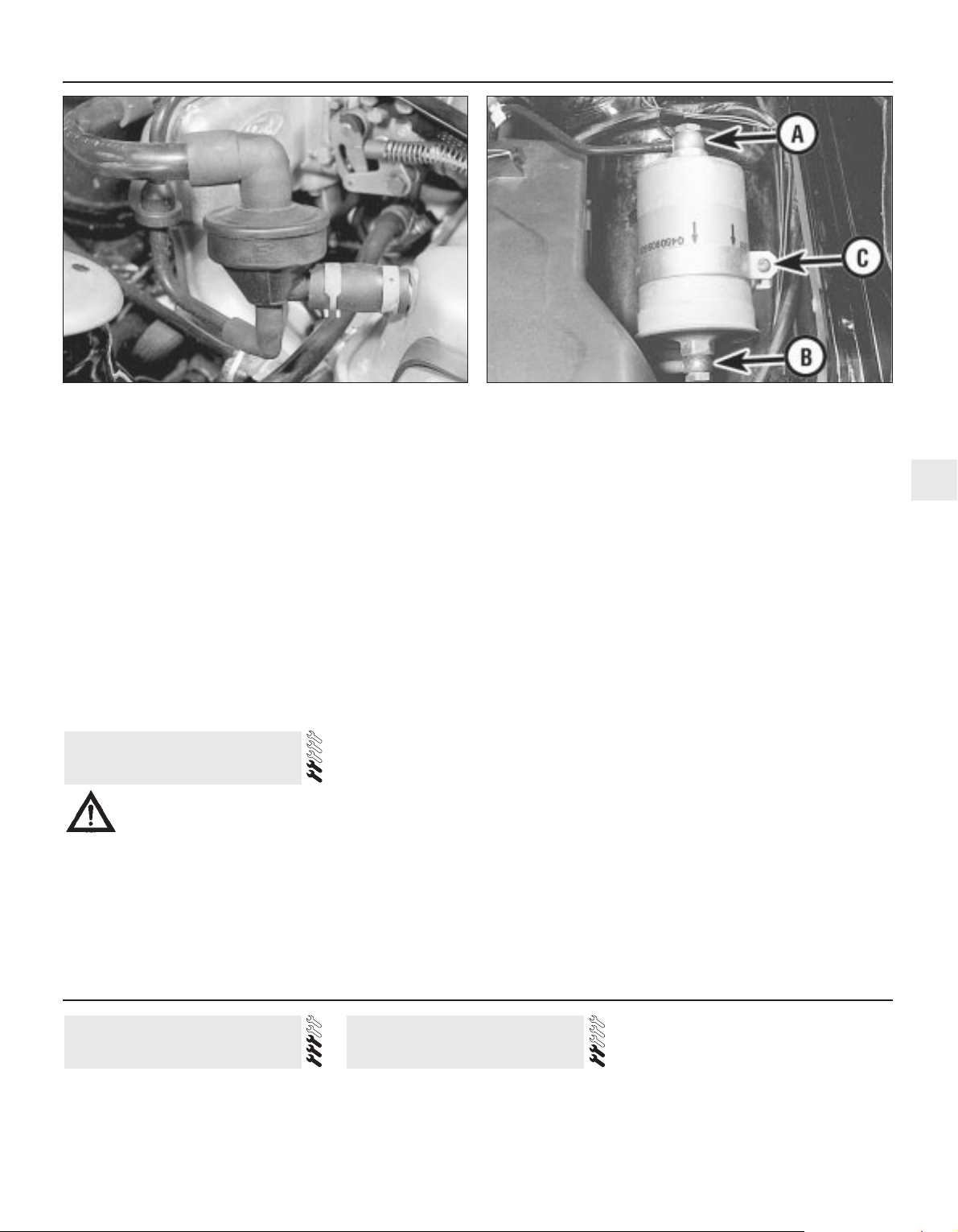
Every 24 000 miles or 2 Years 1•23
1
3 Ensure that the sealing grommet is in
position in the air cleaner before pushing a
new filter into place.
Bosch K-Jetronic and KE-Jetronic
fuel injection engines
4 The filter is located on the right-hand side
of the engine and can be removed after
disconnecting the hoses (see illustration). On
early versions, detach the filter from its
support bracket.
5 Refitting is a reversal of removal, ensuring
that the hoses are correctly reconnected.
Electronic Fuel Injection (EFI)
engines
6 The filter is located in the hose run to the air
cleaner. Note the locations of the hoses to
ensure correct reconnection.
Bosch K-Jetronic and KE-Jetronic
fuel injection models
1 Disconnect the battery negative lead.
2 Relieve the system pressure (Chapter 4,
Part B).
3 Place absorbent rags beneath the filter and
disconnect the fuel inlet and outlet
connections (see illustration).
4 Slacken the clamp bracket screw and
withdraw the filter from the bracket.
5 Refitting is the reversal of removal, but
ensure that the arrows on the filter body point
in the direction of fuel flow; ie towards the
outlet pipe union. On completion check for
fuel leaks with the engine running.
Central Fuel Injection (CFI)
models
6 Disconnect the battery negative lead.
7 Position a suitable container beneath the
fuel filter to catch any escaping fuel, then
slowly slacken the fuel inlet pipe union,
allowing the pressure in the fuel line to
dissipate. When fully dissipated, disconnect
the fuel inlet and outlet pipe unions. Take
adequate fire precautions.
8 Note the orientation of the flow direction
markings on the filter casing, then remove the
clamp bolt and withdraw the filter from the
vehicle. Note that the filter will still contain
fuel, and care should be taken to avoid
spillage.
9 Refitting is a reversal of the removal
procedure, but ensure that the flow direction
markings on the filter casing are correctly
orientated, and tighten the unions to the
specified torque.
10 On completion, switch the ignition on and
off at least five times, and check for fuel
leakage.
Electronic Fuel Injection (EFI)
models
11 The filter is located in the engine
compartment.
12 Depressurise the fuel system as
described in Chapter 4, Part D, then
disconnect the inlet and outlet unions from
the filter.
13 Note the orientation of the flow direction
markings on the filter casing, then remove the
clamp bolt and withdraw the filter from the
vehicle. Note that the filter will still contain
fuel, and care should be taken to avoid
spillage.
14 Refitting is a reversal of the removal
procedure, but ensure that the flow direction
markings on the filter casing are correctly
orientated, and tighten the unions to the
specified torque.
15 On completion, switch the ignition on and
off at least five times, and check for fuel
leakage.
36 Fuel filter renewal - fuel
injection engines
Refer to Chapter 2, Part B. 1 Inspect the thickness of the friction linings
on the disc pads and brake shoes (as
described earlier in this Chapter) at the
intervals specified.
2 The rigid and flexible hydraulic pipes and
hoses should be inspected for leaks or
damage regularly. Although the rigid lines are
plastic-coated in order to preserve them
against corrosion, check for damage which
may have occurred through flying stones,
careless jacking or the traversing of rough
ground.
38 Brake components check
37 Timing belt renewal - CVH
engines
Every 36 000 miles or 3 years
35.4 Crankcase ventilation filter location on KE-Jetronic fuel
injection engines
36.3 Fuel filter inlet pipe (A), outlet pipe (B) and clamp screw (C)
Warning: This procedure may
result in some fuel spillage. Before
carrying out any operation on the
fuel system refer to the
precautions given in Safety First! at the
beginning of this manual and follow them
implicitly. Petrol is a highly dangerous and
volatile liquid and the precautions necessary
when handling it cannot be overstressed.

3 Bend the hydraulic flexible hoses sharply
with the fingers and examine the surface of
the hose for signs of cracking or perishing of
the rubber. Renew if evident.
4 Renew the brake fluid at the specified
intervals and examine all rubber components
(including master cylinder and piston seals)
with a critical eye, renewing where necessary.
1 The procedure is similar to that for the
bleeding of the hydraulic system as described
in Chapter 9, except that the brake fluid
reservoir should be emptied by siphoning,
using a clean poultry baster or similar before
starting, and allowance should be made for
the old fluid to be expelled when bleeding a
section of the circuit.
2 Working as described in Chapter 9, open
the first bleed screw in the sequence, and
pump the brake pedal gently until nearly all
the old fluid has been emptied from the
master cylinder reservoir. Top-up to the
“MAX” level with new fluid, and continue
pumping until only the new fluid remains in the
reservoir, and new fluid can be seen emerging
from the bleed screw. Tighten the screw, and
top the reservoir level up to the “MAX” level
line.
3 Old hydraulic fluid is invariably much darker
in colour than the new, making it easy to
distinguish the two.
4 Work through all the remaining bleed
screws in the sequence until new fluid can be
seen at all of them. Be careful to keep the
master cylinder reservoir topped-up to above
the “MIN” level at all times, or air may enter
the system and greatly increase the length of
the task.
5 When the operation is complete, check that
all bleed screws are securely tightened, and
that their dust caps are refitted. Wash off all
traces of spilt fluid, and recheck the master
cylinder reservoir fluid level.
6 Check the operation of the brakes before
taking the car on the road.
39 Brake fluid renewal
1•24 Every 36 000 miles or 3 Years
Warning: Brake hydraulic fluid
can harm your eyes and damage
painted surfaces, so use extreme
caution when handling and
pouring it. Do not use fluid that has been
standing open for some time, as it
absorbs moisture from the air. Excess
moisture can cause a dangerous loss of
braking effectiveness.

Chapter 2 Part A:
OHV and HCS engines
Crankcase emission control filter renewal . . . . . . . . . .See Chapter 1
Crankshaft front oil seal - renewal . . . . . . . . . . . . . . . . . . . . . . . . . . .7
Cylinder head - removal and refitting . . . . . . . . . . . . . . . . . . . . . . . . .4
Cylinder head and pistons - decarbonising . . . . . . . . . . . . . . . . . . .14
Engine - complete dismantling . . . . . . . . . . . . . . . . . . . . . . . . . . . . .12
Engine - method of removal . . . . . . . . . . . . . . . . . . . . . . . . . . . . . . .11
Engine - reassembly . . . . . . . . . . . . . . . . . . . . . . . . . . . . . . . . . . . . .15
Engine oil and filter renewal . . . . . . . . . . . . . . . . . . . . .See Chapter 1
Engine oil level check . . . . . . . . . . . . . . . . . . . . .See “
Weekly checks”
Engine/transmission mountings - removal and refitting . . . . . . . . . . .9
Engine/transmission - reconnection and installation . . . . . . . . . . . .16
Engine/transmission - removal and separation . . . . . . . . . . . . . . . .11
Examination and renovation . . . . . . . . . . . . . . . . . . . . . . . . . . . . . . .13
General information . . . . . . . . . . . . . . . . . . . . . . . . . . . . . . . . . . . . . .1
Major operations possible with the engine in the car . . . . . . . . . . . . .2
Major operations requiring engine removal . . . . . . . . . . . . . . . . . . . .3
Oil filler cap cleaning . . . . . . . . . . . . . . . . . . . . . . . . . . .See Chapter 1
Oil pump - removal and refitting . . . . . . . . . . . . . . . . . . . . . . . . . . . .10
Piston/connecting rod assemblies removal and refitting . . . . . . . . . .8
Rocker gear - dismantling and reassembly . . . . . . . . . . . . . . . . . . . .6
Sump - removal and refitting . . . . . . . . . . . . . . . . . . . . . . . . . . . . . . .5
Valve clearance adjustment . . . . . . . . . . . . . . . . . . . . .See Chapter 1
General
Engine type . . . . . . . . . . . . . . . . . . . . . . . . . . . . . . . . . . . . . . . . . . . . . . . Four-cylinder, in-line overhead valve
Capacity:
1.1 litre:
OHV engines . . . . . . . . . . . . . . . . . . . . . . . . . . . . . . . . . . . . . . . . . . 1117 cc
HCS engines . . . . . . . . . . . . . . . . . . . . . . . . . . . . . . . . . . . . . . . . . . 1118 cc
1.3 litre . . . . . . . . . . . . . . . . . . . . . . . . . . . . . . . . . . . . . . . . . . . . . . . . 1297 cc
Bore:
All except 1.1 litre HCS engine . . . . . . . . . . . . . . . . . . . . . . . . . . . . . . 73.96 mm
1.1 litre HCS engine . . . . . . . . . . . . . . . . . . . . . . . . . . . . . . . . . . . . . . 68.68 mm
Stroke:
All except 1.1 litre OHV engine . . . . . . . . . . . . . . . . . . . . . . . . . . . . . . 75.48 mm
1.1 litre OHV engine . . . . . . . . . . . . . . . . . . . . . . . . . . . . . . . . . . . . . . 64.98 mm
Compression ratio:
1.1 litre OHV engines (pre-1986) . . . . . . . . . . . . . . . . . . . . . . . . . . . . . 9.15:1
1.1 litre OHV engines (1986 onwards) . . . . . . . . . . . . . . . . . . . . . . . . . 9.5:1
1.1 litre HCS engines . . . . . . . . . . . . . . . . . . . . . . . . . . . . . . . . . . . . . 9.5:1
1.3 litre OHV engines . . . . . . . . . . . . . . . . . . . . . . . . . . . . . . . . . . . . . 9.3:1
1.3 litre HCS engines . . . . . . . . . . . . . . . . . . . . . . . . . . . . . . . . . . . . . 9.5:1
Firing order . . . . . . . . . . . . . . . . . . . . . . . . . . . . . . . . . . . . . . . . . . . . . . . 1-2-4-3 (No 1 at timing cover end)
Cylinder block
Material . . . . . . . . . . . . . . . . . . . . . . . . . . . . . . . . . . . . . . . . . . . . . . . . . . Cast iron
Number of main bearings:
1.1 litre . . . . . . . . . . . . . . . . . . . . . . . . . . . . . . . . . . . . . . . . . . . . . . . . 3
1.3 litre . . . . . . . . . . . . . . . . . . . . . . . . . . . . . . . . . . . . . . . . . . . . . . . . 5
Cylinder bore diameter:
All except 1.1 litre HCS engines:
Standard (1) . . . . . . . . . . . . . . . . . . . . . . . . . . . . . . . . . . . . . . . . . . . 73.940 to 73.950 mm
Standard (2) . . . . . . . . . . . . . . . . . . . . . . . . . . . . . . . . . . . . . . . . . . . 73.950 to 73.960 mm
Standard (3) . . . . . . . . . . . . . . . . . . . . . . . . . . . . . . . . . . . . . . . . . . . 73.960 to 73.970 mm
Standard (4) - all except HCS engines . . . . . . . . . . . . . . . . . . . . . . 73.970 to 73.980 mm
Oversize 0.5 mm . . . . . . . . . . . . . . . . . . . . . . . . . . . . . . . . . . . . . . . 74.500 to 74.510 mm
Oversize 1.0 mm . . . . . . . . . . . . . . . . . . . . . . . . . . . . . . . . . . . . . . . 75.000 to 75.010 mm
2A•1
Easy, suitable for
novice with little
experience
Fairly easy, suitable
for beginner with
some experience
Fairly difficult,
suitable for competent
DIY mechanic
Difficult, suitable for
experienced DIY
mechanic
Very difficult,
suitable for expert DIY
or professional
Degrees of difficulty
Specifications
Contents
2A

2A•2 OHV and HCS engines
Cylinder bore diameter (continued):
1.1 litre HCS engine:
Standard (1) . . . . . . . . . . . . . . . . . . . . . . . . . . . . . . . . . . . . . . . . . . . 68.680 to 68.690 mm
Standard (2) . . . . . . . . . . . . . . . . . . . . . . . . . . . . . . . . . . . . . . . . . . . 68.690 to 68.700 mm
Standard (3) . . . . . . . . . . . . . . . . . . . . . . . . . . . . . . . . . . . . . . . . . . . 68.700 to 68.710 mm
Oversize 0.5 mm . . . . . . . . . . . . . . . . . . . . . . . . . . . . . . . . . . . . . . . 69.200 to 69.210 mm
Oversize 1.0 mm . . . . . . . . . . . . . . . . . . . . . . . . . . . . . . . . . . . . . . . 69.700 to 69.710 mm
Main bearing shell inner diameter:
Standard . . . . . . . . . . . . . . . . . . . . . . . . . . . . . . . . . . . . . . . . . . . . . . . 57.009 to 57.036 mm
0.254 mm undersize . . . . . . . . . . . . . . . . . . . . . . . . . . . . . . . . . . . . . . 56.755 to 56.782 mm
0.508 mm undersize . . . . . . . . . . . . . . . . . . . . . . . . . . . . . . . . . . . . . . 56.501 to 56.528 mm
0.762 mm undersize . . . . . . . . . . . . . . . . . . . . . . . . . . . . . . . . . . . . . . 56.247 to 56.274 mm
Camshaft bearing inner diameter . . . . . . . . . . . . . . . . . . . . . . . . . . . . . . 39.662 to 39.682 mm
Crankshaft
Main bearing journal diameter:
Standard . . . . . . . . . . . . . . . . . . . . . . . . . . . . . . . . . . . . . . . . . . . . . . . 56.990 to 57.000 mm
Standard with yellow dot (1.1 litre only) . . . . . . . . . . . . . . . . . . . . . . . 56.980 to 56.990 mm
0.254 mm undersize . . . . . . . . . . . . . . . . . . . . . . . . . . . . . . . . . . . . . . 56.726 to 56.746 mm
0.508 mm undersize . . . . . . . . . . . . . . . . . . . . . . . . . . . . . . . . . . . . . . 56.472 to 56.492 mm
0.762 mm undersize . . . . . . . . . . . . . . . . . . . . . . . . . . . . . . . . . . . . . . 56.218 to 56.238 mm
Main bearing running clearance:
All except 1.3 litre HCS engine . . . . . . . . . . . . . . . . . . . . . . . . . . . . . . 0.009 to 0.046 mm
1.3 litre HCS engine . . . . . . . . . . . . . . . . . . . . . . . . . . . . . . . . . . . . . . 0.009 to 0.056 mm
Crankpin (big-end) diameter:
OHV engines:
Standard . . . . . . . . . . . . . . . . . . . . . . . . . . . . . . . . . . . . . . . . . . . . . 42.99 to 43.01 mm
0.254 mm undersize . . . . . . . . . . . . . . . . . . . . . . . . . . . . . . . . . . . . 42.74 to 42.76 mm
0.508 mm undersize . . . . . . . . . . . . . . . . . . . . . . . . . . . . . . . . . . . . 42.49 to 42.51 mm
0.762 mm undersize . . . . . . . . . . . . . . . . . . . . . . . . . . . . . . . . . . . . 42.24 to 42.26 mm
HCS engines:
Standard . . . . . . . . . . . . . . . . . . . . . . . . . . . . . . . . . . . . . . . . . . . . . 40.99 to 41.01 mm
0.254 mm undersize . . . . . . . . . . . . . . . . . . . . . . . . . . . . . . . . . . . . 40.74 to 40.76 mm
0.508 mm undersize . . . . . . . . . . . . . . . . . . . . . . . . . . . . . . . . . . . . 40.49 to 40.51 mm
0.762 mm undersize . . . . . . . . . . . . . . . . . . . . . . . . . . . . . . . . . . . . 40.24 to 40.26 mm
Thrustwasher thickness:
Standard . . . . . . . . . . . . . . . . . . . . . . . . . . . . . . . . . . . . . . . . . . . . . . . 2.80 to 2.85 mm
Oversize . . . . . . . . . . . . . . . . . . . . . . . . . . . . . . . . . . . . . . . . . . . . . . . 2.99 to 3.04 mm
Crankshaft endfloat:
OHV engines . . . . . . . . . . . . . . . . . . . . . . . . . . . . . . . . . . . . . . . . . . . . 0.079 to 0.279 mm
HCS engines . . . . . . . . . . . . . . . . . . . . . . . . . . . . . . . . . . . . . . . . . . . . 0.075 to 0.285 mm
Maximum permissible journal and crankpin ovality and taper . . . . . . . . 0.0254 mm
Camshaft
Number of bearings . . . . . . . . . . . . . . . . . . . . . . . . . . . . . . . . . . . . . . . . 3
Drive . . . . . . . . . . . . . . . . . . . . . . . . . . . . . . . . . . . . . . . . . . . . . . . . . . . . Single chain
Thrust plate thickness . . . . . . . . . . . . . . . . . . . . . . . . . . . . . . . . . . . . . . . 4.457 to 4.508 mm
Camshaft bearing diameter . . . . . . . . . . . . . . . . . . . . . . . . . . . . . . . . . . 39.615 to 39.636 mm
Camshaft bearing bush internal diameter . . . . . . . . . . . . . . . . . . . . . . . . 39.662 to 39.682 mm
Camshaft endfloat . . . . . . . . . . . . . . . . . . . . . . . . . . . . . . . . . . . . . . . . . 0.02 to 0.19 mm
Number of links/Length of drive chain . . . . . . . . . . . . . . . . . . . . . . . . . . 46/438.15 mm
Piston and piston rings
Diameter:
All except 1.1 litre HCS engines:
Standard (1) . . . . . . . . . . . . . . . . . . . . . . . . . . . . . . . . . . . . . . . . . . . 73.910 to 73.920 mm
Standard (2) . . . . . . . . . . . . . . . . . . . . . . . . . . . . . . . . . . . . . . . . . . . 73.920 to 73.930 mm
Standard (3) . . . . . . . . . . . . . . . . . . . . . . . . . . . . . . . . . . . . . . . . . . . 73.930 to 73.940 mm
Standard (4) . . . . . . . . . . . . . . . . . . . . . . . . . . . . . . . . . . . . . . . . . . . 73.940 to 73.950 mm
0.5 mm oversize . . . . . . . . . . . . . . . . . . . . . . . . . . . . . . . . . . . . . . . 74.460 to 74.485 mm
1.0 mm oversize . . . . . . . . . . . . . . . . . . . . . . . . . . . . . . . . . . . . . . . 74.960 to 74.985 mm
1.1 litre HCS engines:
Standard (1) . . . . . . . . . . . . . . . . . . . . . . . . . . . . . . . . . . . . . . . . . . . 68.65 to 68.66 mm
Standard (2) . . . . . . . . . . . . . . . . . . . . . . . . . . . . . . . . . . . . . . . . . . . 68.66 to 68.67 mm
Standard (3) . . . . . . . . . . . . . . . . . . . . . . . . . . . . . . . . . . . . . . . . . . . 68.67 to 68.68 mm
0.5 mm oversize . . . . . . . . . . . . . . . . . . . . . . . . . . . . . . . . . . . . . . . 69.20 to 69.21 mm
1.0 mm oversize . . . . . . . . . . . . . . . . . . . . . . . . . . . . . . . . . . . . . . . 69.70 to 69.71 mm
Piston-to-bore clearance . . . . . . . . . . . . . . . . . . . . . . . . . . . . . . . . . . . . 0.015 to 0.050 mm
Piston ring end gap:
Compression . . . . . . . . . . . . . . . . . . . . . . . . . . . . . . . . . . . . . . . . . . . . 0.25 to 0.45 mm
Oil control . . . . . . . . . . . . . . . . . . . . . . . . . . . . . . . . . . . . . . . . . . . . . . 0.20 to 0.40 mm

OHV and HCS engines 2A•3
2A
Cylinder head
Material . . . . . . . . . . . . . . . . . . . . . . . . . . . . . . . . . . . . . . . . . . . . . . . . . . Cast iron
Maximum permissible cylinder head distortion measured over
entire length . . . . . . . . . . . . . . . . . . . . . . . . . . . . . . . . . . . . . . . . . . . . 0.15 mm
Minimum combustion chamber depth after skimming:
OHV engines . . . . . . . . . . . . . . . . . . . . . . . . . . . . . . . . . . . . . . . . . . . . 9.07 mm
HCS engines . . . . . . . . . . . . . . . . . . . . . . . . . . . . . . . . . . . . . . . . . . . . 14.4 ± 0.15 mm
Valve seat angle . . . . . . . . . . . . . . . . . . . . . . . . . . . . . . . . . . . . . . . . . . . 45°
Valve seat width:
OHV engines:
Inlet . . . . . . . . . . . . . . . . . . . . . . . . . . . . . . . . . . . . . . . . . . . . . . . . . 1.20 to 1.75 mm
Exhaust . . . . . . . . . . . . . . . . . . . . . . . . . . . . . . . . . . . . . . . . . . . . . . 1.20 to 1.70 mm
HCS engines (inlet and exhaust) . . . . . . . . . . . . . . . . . . . . . . . . . . . . . 1.18 to 1.75 mm
Seat cutter correction angle:
Upper . . . . . . . . . . . . . . . . . . . . . . . . . . . . . . . . . . . . . . . . . . . . . . . . . 30°
Lower . . . . . . . . . . . . . . . . . . . . . . . . . . . . . . . . . . . . . . . . . . . . . . . . . 75°
Valve guide bore (standard) . . . . . . . . . . . . . . . . . . . . . . . . . . . . . . . . . . 7.907 to 7.938 mm
Valves - general
Operation . . . . . . . . . . . . . . . . . . . . . . . . . . . . . . . . . . . . . . . . . . . . . . . . Cam followers and pushrods
Valve timing:
Pre-1986 OHV engines:
Inlet valve opens . . . . . . . . . . . . . . . . . . . . . . . . . . . . . . . . . . . . . . . 21° BTDC
Inlet valve closes . . . . . . . . . . . . . . . . . . . . . . . . . . . . . . . . . . . . . . . 55° ABDC
Exhaust valve opens . . . . . . . . . . . . . . . . . . . . . . . . . . . . . . . . . . . . 70° BBDC
Exhaust valve closes . . . . . . . . . . . . . . . . . . . . . . . . . . . . . . . . . . . . 22° ATDC
1986 onwards OHV engines:
Inlet valve opens . . . . . . . . . . . . . . . . . . . . . . . . . . . . . . . . . . . . . . . 14° BTDC
Inlet valve closes . . . . . . . . . . . . . . . . . . . . . . . . . . . . . . . . . . . . . . . 46° ABDC
Exhaust valve opens . . . . . . . . . . . . . . . . . . . . . . . . . . . . . . . . . . . . 65° BBDC
Exhaust valve closes . . . . . . . . . . . . . . . . . . . . . . . . . . . . . . . . . . . . 11° ATDC
1.1 litre HCS engines:
Inlet opens . . . . . . . . . . . . . . . . . . . . . . . . . . . . . . . . . . . . . . . . . . . . 14° BTDC
Inlet closes . . . . . . . . . . . . . . . . . . . . . . . . . . . . . . . . . . . . . . . . . . . 46° ABDC
Exhaust opens . . . . . . . . . . . . . . . . . . . . . . . . . . . . . . . . . . . . . . . . 49° BBDC
Exhaust closes . . . . . . . . . . . . . . . . . . . . . . . . . . . . . . . . . . . . . . . . 11° ATDC
1.3 litre HCS engines:
Inlet opens . . . . . . . . . . . . . . . . . . . . . . . . . . . . . . . . . . . . . . . . . . . . 16° BTDC
Inlet closes . . . . . . . . . . . . . . . . . . . . . . . . . . . . . . . . . . . . . . . . . . . 44° ABDC
Exhaust opens . . . . . . . . . . . . . . . . . . . . . . . . . . . . . . . . . . . . . . . . 51° BBDC
Exhaust closes . . . . . . . . . . . . . . . . . . . . . . . . . . . . . . . . . . . . . . . . 9° ATDC
Valve clearance (cold):
Inlet . . . . . . . . . . . . . . . . . . . . . . . . . . . . . . . . . . . . . . . . . . . . . . . . . . . 0.22 mm
Exhaust:
OHV engines . . . . . . . . . . . . . . . . . . . . . . . . . . . . . . . . . . . . . . . . . . 0.59 mm
HCS engines . . . . . . . . . . . . . . . . . . . . . . . . . . . . . . . . . . . . . . . . . . 0.32 mm
Cam follower diameter . . . . . . . . . . . . . . . . . . . . . . . . . . . . . . . . . . . . . . 13.081 to 13.094 mm
Cam follower clearance in bore . . . . . . . . . . . . . . . . . . . . . . . . . . . . . . . 0.016 to 0.062 mm
Valve spring free length:
OHV engines:
Pre-1986 . . . . . . . . . . . . . . . . . . . . . . . . . . . . . . . . . . . . . . . . . . . . . 42.0 mm
1986 onwards:
1.1 litre . . . . . . . . . . . . . . . . . . . . . . . . . . . . . . . . . . . . . . . . . . . . . 41.2 mm
1.3 litre . . . . . . . . . . . . . . . . . . . . . . . . . . . . . . . . . . . . . . . . . . . . . 42.4 mm
HCS engines . . . . . . . . . . . . . . . . . . . . . . . . . . . . . . . . . . . . . . . . . . . . 41.0 mm
Inlet valve
Length:
OHV engines . . . . . . . . . . . . . . . . . . . . . . . . . . . . . . . . . . . . . . . . . . . . 105.45 to 106.45 mm
HCS engines . . . . . . . . . . . . . . . . . . . . . . . . . . . . . . . . . . . . . . . . . . . . 103.70 to 104.40 mm
Head diameter:
OHV engines:
Pre-1986 . . . . . . . . . . . . . . . . . . . . . . . . . . . . . . . . . . . . . . . . . . . . . 38.02 to 38.28 mm
1986 onwards:
1.1 litre . . . . . . . . . . . . . . . . . . . . . . . . . . . . . . . . . . . . . . . . . . . . . 32.89 to 33.15 mm
1.3 litre . . . . . . . . . . . . . . . . . . . . . . . . . . . . . . . . . . . . . . . . . . . . . 38.02 to 38.28 mm
HCS engines:
1.1 litre . . . . . . . . . . . . . . . . . . . . . . . . . . . . . . . . . . . . . . . . . . . . . . 32.90 to 33.10 mm
1.3 litre . . . . . . . . . . . . . . . . . . . . . . . . . . . . . . . . . . . . . . . . . . . . . . 34.40 to 34.60 mm

2A•4 OHV and HCS engines
Inlet valve (continued)
Stem diameter:
OHV engines:
Standard . . . . . . . . . . . . . . . . . . . . . . . . . . . . . . . . . . . . . . . . . . . . . 7.866 to 7.868 mm
0.076 mm oversize . . . . . . . . . . . . . . . . . . . . . . . . . . . . . . . . . . . . . 7.944 to 7.962 mm
0.38 mm oversize . . . . . . . . . . . . . . . . . . . . . . . . . . . . . . . . . . . . . . 8.249 to 8.267 mm
HCS engines:
Standard . . . . . . . . . . . . . . . . . . . . . . . . . . . . . . . . . . . . . . . . . . . . . 7.025 to 7.043 mm
0.076 mm oversize . . . . . . . . . . . . . . . . . . . . . . . . . . . . . . . . . . . . . 7.225 to 7.243 mm
0.381 mm oversize . . . . . . . . . . . . . . . . . . . . . . . . . . . . . . . . . . . . . 7.425 to 7.443 mm
Valve stem clearance in guide . . . . . . . . . . . . . . . . . . . . . . . . . . . . . . . . 0.021 to 0.070 mm
Exhaust valve
Length:
OHV engines:
Pre-1986 . . . . . . . . . . . . . . . . . . . . . . . . . . . . . . . . . . . . . . . . . . . . . 105.15 to 106.15 mm
1986 onwards . . . . . . . . . . . . . . . . . . . . . . . . . . . . . . . . . . . . . . . . . 106.04 to 107.04 mm
HCS engines . . . . . . . . . . . . . . . . . . . . . . . . . . . . . . . . . . . . . . . . . . . . 104.02 to 104.72 mm
Head diameter:
OHV engines . . . . . . . . . . . . . . . . . . . . . . . . . . . . . . . . . . . . . . . . . . . . 29.01 to 29.27 mm
HCS engines . . . . . . . . . . . . . . . . . . . . . . . . . . . . . . . . . . . . . . . . . . . . 28.90 to 29.10 mm
Stem diameter:
OHV engines:
Standard . . . . . . . . . . . . . . . . . . . . . . . . . . . . . . . . . . . . . . . . . . . . . 7.846 to 7.864 mm
0.076 mm oversize . . . . . . . . . . . . . . . . . . . . . . . . . . . . . . . . . . . . . 7.922 to 7.940 mm
0.38 mm oversize . . . . . . . . . . . . . . . . . . . . . . . . . . . . . . . . . . . . . . 8.227 to 8.245 mm
HCS engines:
Standard . . . . . . . . . . . . . . . . . . . . . . . . . . . . . . . . . . . . . . . . . . . . . 6.999 to 7.017 mm
0.076 mm oversize . . . . . . . . . . . . . . . . . . . . . . . . . . . . . . . . . . . . . 7.199 to 7.217 mm
0.381 mm oversize . . . . . . . . . . . . . . . . . . . . . . . . . . . . . . . . . . . . . 7.399 to 7.417 mm
Valve stem clearance in guide . . . . . . . . . . . . . . . . . . . . . . . . . . . . . . . . 0.043 to 0.092 mm
Lubrication system
Oil pump type . . . . . . . . . . . . . . . . . . . . . . . . . . . . . . . . . . . . . . . . . . . . . Rotor, external driven by gear on camshaft
Minimum oil pressure at 80° C (175° F):
Engine speed 750 rpm . . . . . . . . . . . . . . . . . . . . . . . . . . . . . . . . . . . . 0.6 bar (8.5 lbf/in
2
)
Engine speed 2000 rpm . . . . . . . . . . . . . . . . . . . . . . . . . . . . . . . . . . . 1.5 bar (21.3 lbf/in2)
Oil pressure warning lamp operates . . . . . . . . . . . . . . . . . . . . . . . . . . . . 0.32 to 0.53 bar (4.5 to 7.5 lbf/in2)
Relief valve opens . . . . . . . . . . . . . . . . . . . . . . . . . . . . . . . . . . . . . . . . . . 2.41 to 2.75 bar (34.3 to 39.1 lbf/in2)
Oil pump clearances:
Outer rotor-to-body . . . . . . . . . . . . . . . . . . . . . . . . . . . . . . . . . . . . . . 0.14 to 0.26 mm
Inner-to-outer rotor . . . . . . . . . . . . . . . . . . . . . . . . . . . . . . . . . . . . . . . 0.051 to 0.127 mm
Rotor endfloat . . . . . . . . . . . . . . . . . . . . . . . . . . . . . . . . . . . . . . . . . . . 0.025 to 0.06 mm
Torque wrench settings Nm lbf ft
Main bearing cap bolts . . . . . . . . . . . . . . . . . . . . . . . . . . . . . . . . . . . . . . 88 to 102 65 to 75
Connecting rod (big-end bearing cap) bolts:
OHV engines . . . . . . . . . . . . . . . . . . . . . . . . . . . . . . . . . . . . . . . . . . . . 29 to 36 21 to 27
HCS engines:
Stage 1 . . . . . . . . . . . . . . . . . . . . . . . . . . . . . . . . . . . . . . . . . . . . . . 4 3
Stage 2 . . . . . . . . . . . . . . . . . . . . . . . . . . . . . . . . . . . . . . . . . . . . . . Tighten by a further 90° Tighten by a further 90°
Rear oil seal retainer bolts . . . . . . . . . . . . . . . . . . . . . . . . . . . . . . . . . . . 16 to 20 12 to 15
Flywheel bolts . . . . . . . . . . . . . . . . . . . . . . . . . . . . . . . . . . . . . . . . . . . . . 64 to 70 47 to 52
Timing chain tensioner . . . . . . . . . . . . . . . . . . . . . . . . . . . . . . . . . . . . . . 7 to 9 5 to 7
Camshaft thrust plate . . . . . . . . . . . . . . . . . . . . . . . . . . . . . . . . . . . . . . . 4 to 5 3 to 4
Camshaft sprocket bolt . . . . . . . . . . . . . . . . . . . . . . . . . . . . . . . . . . . . . 16 to 20 12 to 15
Timing cover bolts . . . . . . . . . . . . . . . . . . . . . . . . . . . . . . . . . . . . . . . . . 7 to 10 5 to 8
Crankshaft pulley bolt:
OHV engines . . . . . . . . . . . . . . . . . . . . . . . . . . . . . . . . . . . . . . . . . . . . 54 to 59 40 to 44
HCS engines . . . . . . . . . . . . . . . . . . . . . . . . . . . . . . . . . . . . . . . . . . . . 100 to 120 74 to 89
Oil pump to crankcase . . . . . . . . . . . . . . . . . . . . . . . . . . . . . . . . . . . . . . 16 to 20 12 to 15
Oil pump cover bolts . . . . . . . . . . . . . . . . . . . . . . . . . . . . . . . . . . . . . . . 8 to 12 6 to 9
Sump bolts:
Stage 1 . . . . . . . . . . . . . . . . . . . . . . . . . . . . . . . . . . . . . . . . . . . . . . . . 6 to 8 4 to 6
Stage 2 . . . . . . . . . . . . . . . . . . . . . . . . . . . . . . . . . . . . . . . . . . . . . . . . 8 to 11 6 to 8
Stage 3 . . . . . . . . . . . . . . . . . . . . . . . . . . . . . . . . . . . . . . . . . . . . . . . . 8 to 11 6 to 8
Sump drain plug . . . . . . . . . . . . . . . . . . . . . . . . . . . . . . . . . . . . . . . . . . . 21 to 28 15 to 21
Oil pressure switch . . . . . . . . . . . . . . . . . . . . . . . . . . . . . . . . . . . . . . . . . 13 to 15 10 to 11
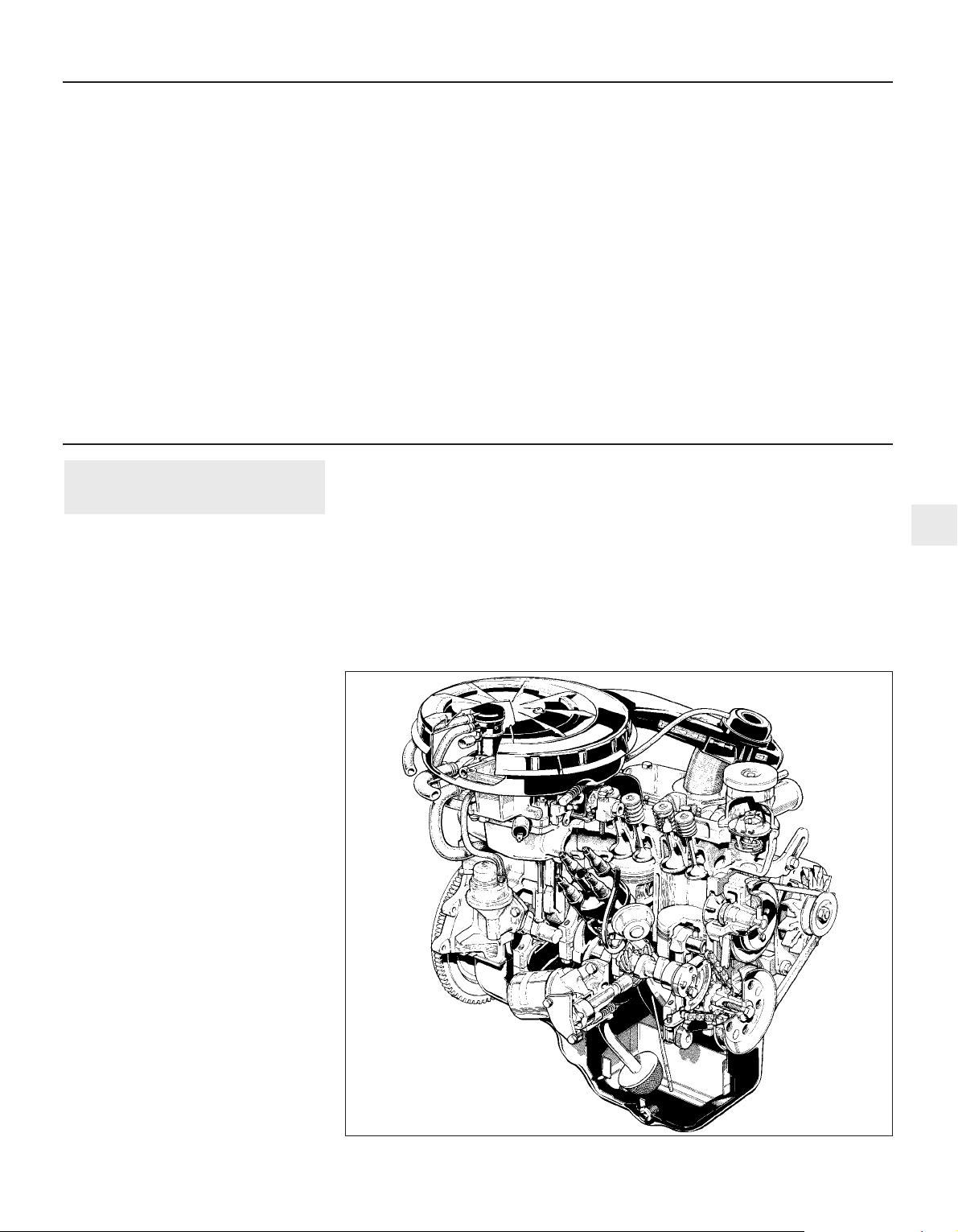
OHV engines
The 1.1 litre and 1.3 litre OHV engines are
of four-cylinder, in-line overhead valve type
(hence OHV), mounted transversely together
with the transmission, at the front of the car.
The crankshaft on 1.1 litre engines is
supported in three shell type main bearings,
whereas the 1.3 litre unit features a five main
bearing crankshaft. Apart from this difference
and other minor alterations, the two engines
are virtually the same in design and
construction.
The connecting rods are attached to the
crankshaft by horizontally split shell type bigend bearings and to the pistons by
interference fit gudgeon pins. The aluminium
alloy pistons are of the slipper type and are
fitted with three piston rings; two
compression and one oil control.
The camshaft is chain driven from the
crankshaft and operates the valves via
pushrods and rocker arms. The inlet and
exhaust valves are each closed by a single
valve spring and operate in guides integral
with the cylinder head. The oil pump and
distributor are driven by a skew gear on the
camshaft while an eccentric cam operates the
fuel pump lever.
The oil pump is mounted externally on the
cylinder block just below the distributor, and
the full flow type oil filter is screwed directly
into the oil pump. Engine oil contained in the
sump is drawn through a strainer and pick-up
tube by an externally mounted oil pump of
twin rotor design. The oil is then forced
through the full-flow, throw-away type oil
filter. Oil pressure is regulated by a relief valve
integral in the oil pump. The pressurised oil is
directed through the various galleries and
passages to all bearing surfaces. A drilling in
the big-end provides lubrication for the
gudgeon pins and cylinder bores. The timing
chain and sprockets are lubricated by an oil
ejection nozzle.
HCS engines
The 1.1 and 1.3 litre High Compression
Swirl (HCS) engines were introduced at the
beginning of 1989 and fitted to certain 1.1
Escort models and all 1.3 Escort models,
including the Van and Combi, replacing the
previous OHV engine.
A further development of the Ford “lean
burn” principle, the HCS engine is basically
similar to the previous OHV engine, being of
four cylinder, in-line OHV construction, but
nearly every aspect of the engine has been redesigned. The major differences are in the
cylinder head, where the inlet valve ports and
combustion chambers are designed to impart
a high level of “swirl” to the incoming fuel/air
mixture. The valve arrangement is also
different, being of “mirror” design, where the
inlet valves of the centre cylinders are next to
each other. Combined with the DIS fully
1 General information
OHV and HCS engines 2A•5
2A
Torque wrench settings (continued) Nm lbf ft
Rocker shaft pedestal bolts . . . . . . . . . . . . . . . . . . . . . . . . . . . . . . . . . . 40 to 46 30 to 34
Cylinder head bolts:
OHV engines:
Stage 1 . . . . . . . . . . . . . . . . . . . . . . . . . . . . . . . . . . . . . . . . . . . . . . 10 to 15 8 to 11
Stage 2 . . . . . . . . . . . . . . . . . . . . . . . . . . . . . . . . . . . . . . . . . . . . . . 40 to 50 30 to 37
Stage 3 . . . . . . . . . . . . . . . . . . . . . . . . . . . . . . . . . . . . . . . . . . . . . . 80 to 90 59 to 66
Stage 4 (after 10 to 20 minutes) . . . . . . . . . . . . . . . . . . . . . . . . . . . 100 to 110 74 to 81
HCS engines:
Stage 1 . . . . . . . . . . . . . . . . . . . . . . . . . . . . . . . . . . . . . . . . . . . . . . 30 22
Stage 2 . . . . . . . . . . . . . . . . . . . . . . . . . . . . . . . . . . . . . . . . . . . . . . Tighten by a further 90° Tighten by a further 90°
Stage 3 . . . . . . . . . . . . . . . . . . . . . . . . . . . . . . . . . . . . . . . . . . . . . . Tighten by a further 90° Tighten by a further 90°
Rocker cover . . . . . . . . . . . . . . . . . . . . . . . . . . . . . . . . . . . . . . . . . . . . . . 4 to 5 3 to 4
Engine to transmission . . . . . . . . . . . . . . . . . . . . . . . . . . . . . . . . . . . . . . 35 to 45 26 to 33
Right-hand engine mounting to body . . . . . . . . . . . . . . . . . . . . . . . . . . . 41 to 58 30 to 43
Right-hand engine mounting bracket to engine . . . . . . . . . . . . . . . . . . . 54 to 72 40 to 53
Right-hand engine mounting rubber insulator to brackets . . . . . . . . . . . 70 to 95 52 to 70
Front transmission mounting bracket to transmission (pre-1986) . . . . . 41 to 51 30 to 38
Front and rear transmission mounting bolts (pre-1986) . . . . . . . . . . . . . 52 to 64 38 to 47
Transmission mountings to transmission (1986 onwards) . . . . . . . . . . . 80 to 100 59 to 74
Transmission support crossmember to body (1986 onwards) . . . . . . . . 52 38
1.1 Cutaway view of the 1.1 litre
OHV engine
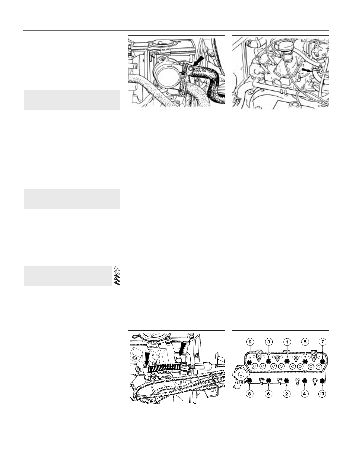
electronic ignition system which has no
moving parts, the result is an economical
engine with cleaner exhaust emissions which
can run on leaded or unleaded fuel without
adjustment to the ignition system.
Although most components of the HCS
engine have been redesigned, for the most
part the servicing and overhaul procedures
remain unchanged, unless otherwise stated.
The following work can be carried out
without having to remove the engine:
a) Cylinder head - removal and refitting.
b) Valve clearances - adjustment (see
Chapter 1).
c) Sump - removal and refitting.
d) Rocker gear - overhaul.
e) Crankshaft front oil seal - renewal .
f) Pistons/connecting rods - removal and
refitting.
g) Engine mountings - renewal.
h) Oil filter - removal and refitting.
I) Oil pump - removal and refitting.
The following work can only be carried out
after removal of the engine from the car:
a) Crankshaft main bearings - renewal .
b) Crankshaft - removal and refitting.
c) Flywheel - removal and refitting.
d) Crankshaft rear oil seal - renewal.
e) Camshaft - removal and refitting.
f) Timing gears and chain - removal and
refitting.
Removal
Note: On HCS engines, cylinder head bolts
may be used a total of three times (including
initial fit) and must be suitably marked to
indicate each removal operation. A new
cylinder head gasket must be used on refitting.
1 If the engine is in the car carry out the
preliminary operations described in
paragraphs 2 to 16.
2 Disconnect the battery negative terminal.
3 Remove the air cleaner (Chapter 4, Part A).
4 Drain the cooling system (Chapter 1).
5 Disconnect the hoses from the thermostat
housing.
6 Disconnect the heater hose from the upper
connection on the automatic choke housing,
or inlet manifold as applicable (see
illustrations).
7 Release the throttle cable from the
carburettor operating lever by moving the
spring clip and removing the bracket fixing
bolt (see illustration).
8 On manual choke models disconnect the
choke cable from the linkage lever and
support bracket.
9 Disconnect the fuel and vacuum pipes from
the carburettor.
10 Disconnect the breather hose from the
inlet manifold.
11 On vehicles with servo-assisted brakes,
disconnect the vacuum hose from the inlet
manifold.
12 Disconnect the HT leads from the spark
plugs.
13 Disconnect the electrical leads from the
temperature sender unit, the anti-run-on
solenoid valve at the carburettor, and the
radiator fan thermal switch.
14 Unbolt and remove the hot air box from
the exhaust manifold.
15 Disconnect the exhaust downpipe from
the manifold by unbolting the connecting
flanges. Support the exhaust system at the
front end.
16 Remove the oil filler cap with breather hose.
17 Extract the four screws and remove the
rocker cover.
18 Unscrew and remove the four fixing bolts
and lift away the rocker shaft assembly from
the cylinder head.
19 Withdraw the pushrods, keeping them in
their originally fitted sequence. A simple way
to do this is to punch holes in a piece of card
and number them 1 to 8 from the thermostat
housing end of the cylinder head.
20 Remove the spark plugs.
21 Unscrew the cylinder head bolts
progressively in the reverse order to that given
for tightening (see illustration 4.27). Remove
the cylinder head.
22 To dismantle the cylinder head, refer to
Section 13.
Refitting
23 Before refitting the cylinder head, remove
every particle of carbon, old gasket and dirt
from the mating surfaces of the cylinder head
and block. Do not let the removed material
drop into the cylinder bores or waterways, if it
does, remove it. Normally, when a cylinder
head is removed, the head is decarbonised
and the valves ground in as described in
Section 14 to remove all trace of carbon.
Clean the threads of the cylinder head bolts
and mop out oil from the bolt holes in the
cylinder block. In extreme cases, screwing a
bolt into an oil-filled hole can cause the block
to fracture due to hydraulic pressure.
24 If there is any doubt about the condition of
the inlet or exhaust gaskets, unbolt the
manifolds and fit new ones to perfectly clean
mating surfaces.
25 Locate a new cylinder head gasket on the
cylinder block, making quite sure that the bolt
holes, coolant passages and lubrication holes
are correctly aligned.
26 Lower the cylinder head carefully into
position on the block.
27 Screw in all the bolts finger tight and then
tighten them in the stages given (see
Specifications), and in the sequence shown to
the specified torque (see illustration). Note that
4 Cylinder head - removal and
refitting
3 Major operations requiring
engine removal
2 Major operations possible with
the engine in the car
2A•6 OHV and HCS engines
4.27 Cylinder head bolt tightening
sequence
4.7 Throttle cable disconnection points
4.6a Heater hose connection on choke
housing
4.6b Heater hose connection at inlet
manifold
 Loading...