


307-01-1 |
Automatic Transaxle/Transmission |
307-01-1 |
ASSEMBLY
Transmission
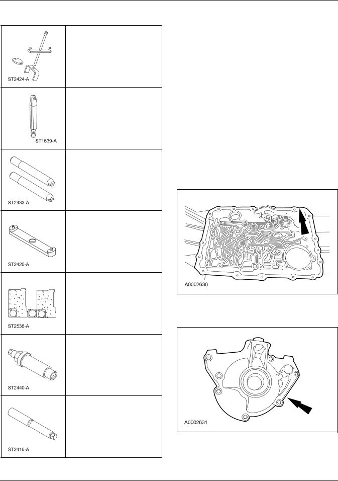
Special Tool(s)
Adjustment Set, Transmission
Band
307-S022 (T71P-77370-A)
Holding Fixture, Transmission
307-003 (T57L-500-B)
Depth Micrometer 303-D026 (D80P-4201-A) or equivalent
Alignment Gauge, TR Sensor
307-351 (T97L-70010-A)
Installer, Transmission
Extension Housing Oil Seal
307-038 (T74P-77052-A)
Sizer, Piston Seal
307-338 (T95L-70010-G)
(Continued)
Special Tool(s)
Alignment Set, Fluid Pump
307-S039 (T74P-77103-X)
Aligner, Fluid Pump Handle 307-431
Aligner, Fluid Pump Pilot 307-432
Gauge Bar 307-400
Compressor, Servo Cover 307-402
Installer, Shift Shaft Fluid Seal
307-050 (T74P-77498-A)
Handle, Torque Converter
307-091 (T81P-7902-C)
(Continued)
Copyright ã 2004, Ford Motor Company
Last updated: 8/11/2005 |
2005 Mustang, 12/2004 |
307-01-2 |
Automatic Transaxle/Transmission |
307-01-2 |
ASSEMBLY (Continued)
Special Tool(s)
Compressor, Cushion Spring 307-401
Aligner, Valve Body
307-334 (T95L-70010-C)
Alignment Pins, Transmission Pump
307-399
Aligner, Flex Plate 307-403
Air Test Plate 307-433-01, 307-433-2, 307-433-3
Installer, Drive Pinion flange 205-479
Installer, Output Shaft Flange 307-404
Material
Item |
Specification |
MERCONâ V Automatic |
MERCONâ V |
Transmission Fluid |
|
XT-5-QM |
|
|
|
Multi-Purpose Grease |
ESR-M1C159-A |
XG-4 |
|
|
|
1.Thoroughly clean the transmission case and extension housing in solvent and blow dry with compressed air.
2.Inspect the transmission case for the following:
•Stripped bolt hole threads
•Gasket and mating surfaces for burrs or nicks
•Obstructions to vent and fluid passages
•Cracks or warpage
3.Inspect the extension housing for cracks, burrs or warpage.
2005 Mustang, 12/2004
307-01-3 |
Automatic Transaxle/Transmission |
307-01-3 |
ASSEMBLY (Continued)
4.Inspect the case bearing for damage. If damage to the case bearing is indicated, install a new case.
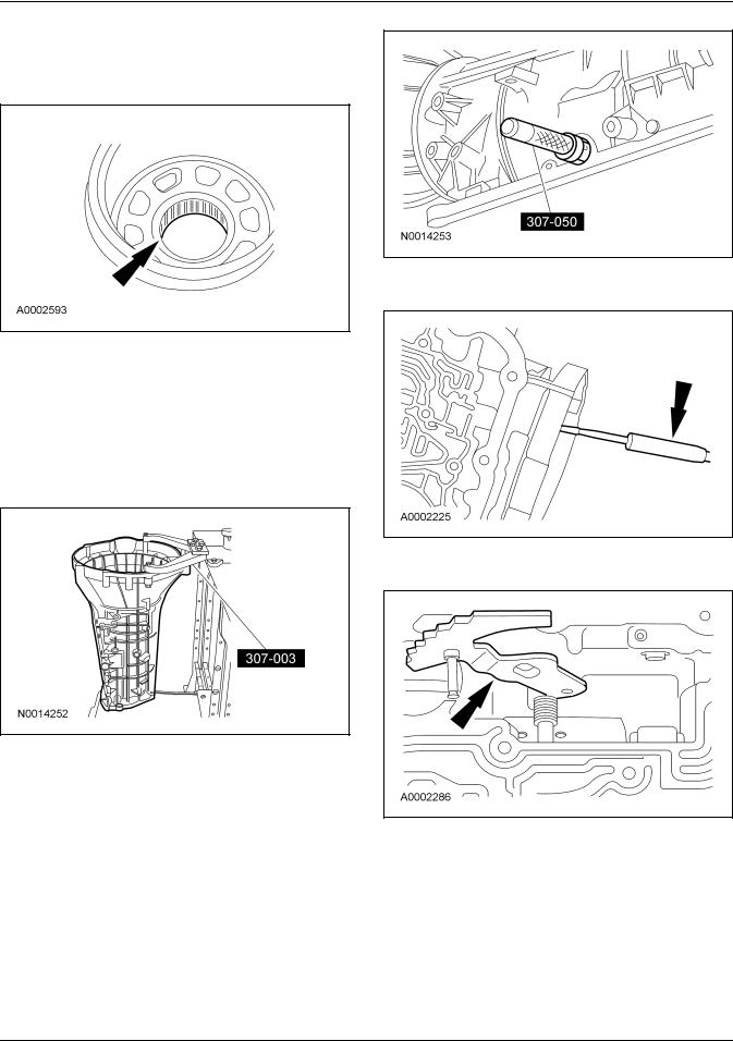
5. WARNING: Make sure the lock pin on bench-mounted holding fixture is secure. Failure to follow these instructions may result in personal injury.
Using the special tool, install the transmission into the bench with the converter housing facing up.
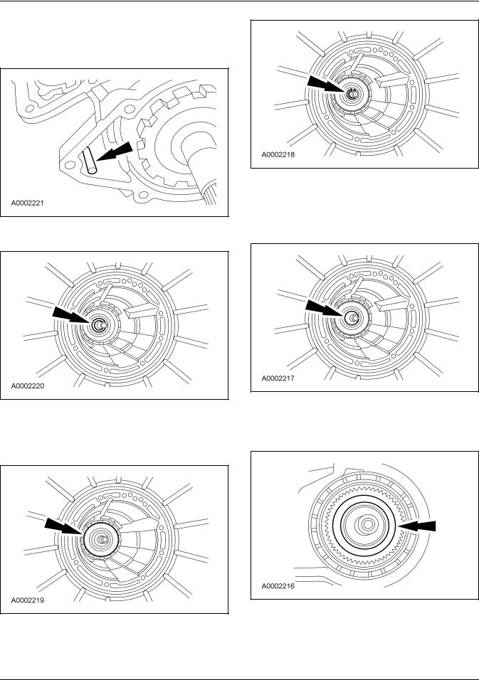
6.Using the special tool, install the manual control lever shaft seal and lubricate it with petroleum jelly.
7.Install the parking lever rod.
8.Install the manual control lever.
2005 Mustang, 12/2004
307-01-4 |
Automatic Transaxle/Transmission |
307-01-4 |
ASSEMBLY (Continued)
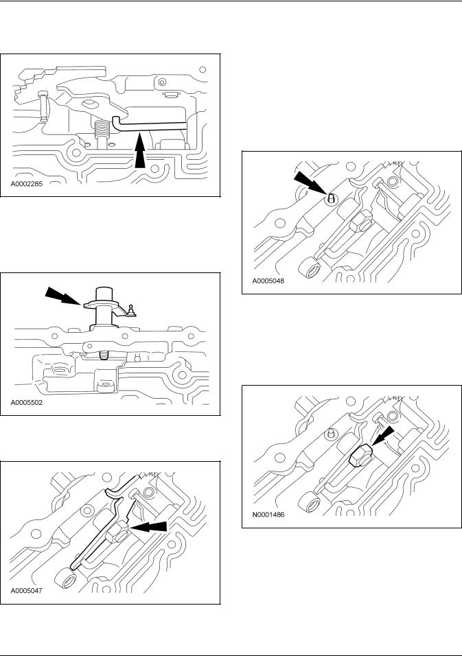
9.Assemble the manual valve inner lever and parking lever actuating rod as shown.
10. CAUTION: Align the flats on the manual valve inner lever with the flats on the manual control lever shaft.
Install the manual control lever shaft.
11.Install the manual valve inner lever onto the manual shaft and loosely install the nut.
12. CAUTION: Use care not to damage the fluid pan rail surface when installing the retaining pin.
NOTE: Align the manual control lever shaft alignment groove with the manual control lever shaft spring pin bore in the transmission case.
Install the manual control lever shaft spring pin.
•Tap the manual control lever shaft spring pin into the transmission case.
13. CAUTION: To avoid damage, do not allow the wrench to strike the manual valve inner lever pin.
Tighten the nut.
• Tighten to 48 Nm (35 lb-ft).
2005 Mustang, 12/2004
307-01-5 |
Automatic Transaxle/Transmission |
307-01-5 |
ASSEMBLY (Continued)
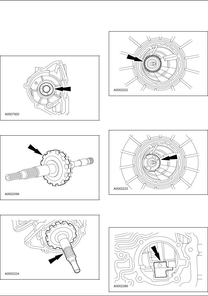
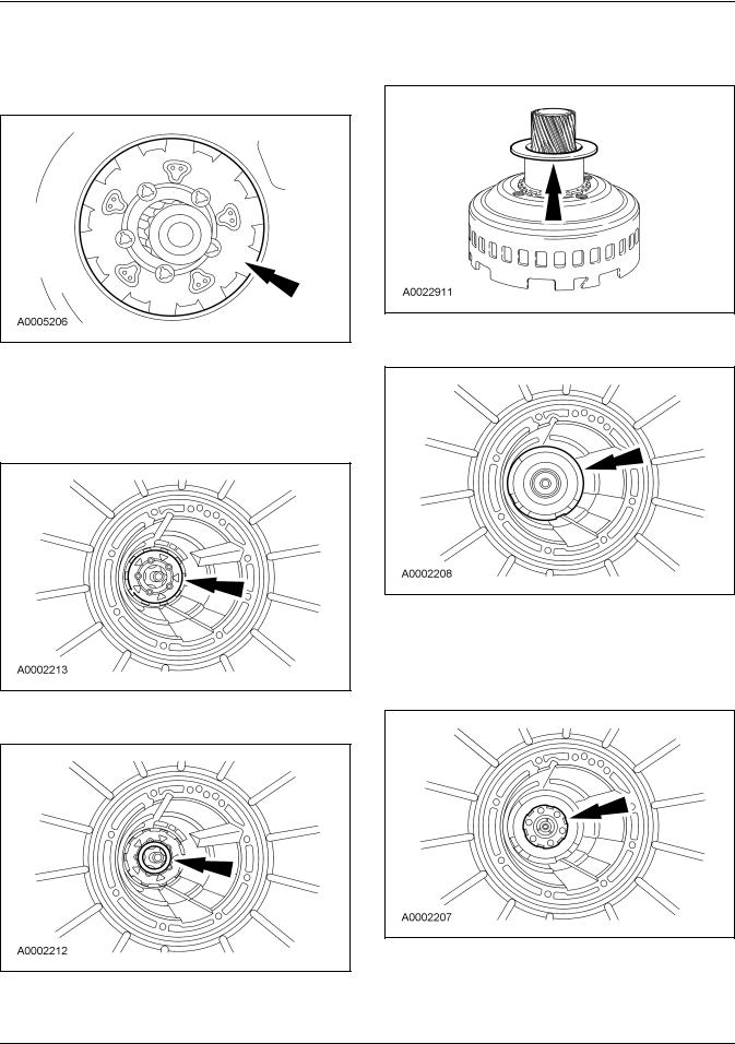
14. CAUTION: The tabs on the output shaft thrust washer (No. 11) point into the case. Make sure the thrust washer is correctly seated.
Install the output shaft thrust washer (No. 11).
•Coat the output shaft thrust washer with petroleum jelly.
15. Install the park gear on the output shaft.
16. Install the output shaft and park gear.
17.Install the low/reverse brake drum.
•Rotate the low/reverse brake drum clockwise to install.
18. CAUTION: Make sure band is resting on the 2 anchor pins in the case.
Install the low/reverse band over the reverse drum.
19.NOTE: The reverse band actuating lever must fit into the notches in the band.
Install the reverse band actuating lever into the reverse band.
2005 Mustang, 12/2004
307-01-6 |
Automatic Transaxle/Transmission |
307-01-6 |
ASSEMBLY (Continued)
20.Install the reverse band actuating lever shaft into the case and into the reverse band actuating lever.
21. Install the No. 10 needle bearing into the case.
22. CAUTION: Do not damage the seal against the case during assembly.
Install the output shaft ring gear, hub and seal.
23. CAUTION: Always install a new output shaft retaining ring.
Install a new output shaft retaining ring.
24.NOTE: Install the output shaft sleeve with the cone facing up. This sleeve will snap into place when correctly installed.
Install the output shaft sleeve.
25.Install low/reverse planetary carrier needle bearing (No. 9) onto the output shaft ring gear and hub assembly.
2005 Mustang, 12/2004
307-01-7 |
Automatic Transaxle/Transmission |
307-01-7 |
ASSEMBLY (Continued)
26. CAUTION: Make sure the needle bearings stay in place.
Install the low/reverse planetary assembly.
27. CAUTION: The low/reverse brake drum must be pulled forward to install the low/reverse planet retaining ring.
Install the retaining ring.
28. Install the No. 8 thrust bearing.
29.Install the spacer on the input shell, using petroleum jelly to hold it in place.
30. Install the input shell and sun gear assembly.
31.NOTE: The No. 13 bearing must be properly seated in the forward planet assembly so the sun gear can be installed correctly.
Install the forward planetary assembly.
2005 Mustang, 12/2004

307-01-8 |
Automatic Transaxle/Transmission |
307-01-8 |
ASSEMBLY (Continued)
32.Install the No. 7 forward planet thrust bearing into the forward ring gear and hub assembly. Use petroleum jelly to hold the bearing in place.
33.Install the No. 6B forward clutch thrust washer onto the forward ring gear hub.
34.Install the forward ring gear and hub as an assembly.
35.Install the No. 6A forward ring gear hub thrust bearing into the forward ring gear and hub.
36. Install the forward clutch cylinder.
37. Install the No. 5 thrust bearing.
2005 Mustang, 12/2004
 Loading...