


MCD425A/W, R425A/W, MFD425A/W, P425A/W
Ice Machines
Operation and Service Manual
MCD425A/W_S |
MCD425A/W_T |
R425A/W |
MFD425A/W_T |
P425A/W
Following installation, please forward this manual to the appropriate operations person.
801 Church Lane • Easton, PA 18040, USA |
|
Toll free (877) 612-5086 • +1 (610) 252-7301 |
01033646R06 |
www.follettice.com |

2 MCD425A/W, R425A/W, MFD425A/W, P425A/W Ice Machines

Contents
Welcome to Follett. . |
. . . . . . . . . . . . . . . . . . . . . |
. . . |
. . . |
. . |
. . . . . . . . . . . . . . . . . . . . . . . . . . . . . . . . . . . . . . . . . . . |
. 4 |
Before you begin.. |
. . . . . . . . . . . |
. . |
. |
. |
. . |
4 |
Specifications. . . |
. . . . . . . . . . . |
. |
. . |
. . . |
5 |
|
Electrical.. . . . . . . . . . . . . . . . . . . . . . . . . . . . . . . . . . . . . . . . . . . . . . . . . . . . . . . . . . . . . . . . . . . . . . . . . . . . . . . . |
5 |
|||||
Plumbing. . . . . . . . . . |
. . . . . . . . . . . . . . . . . . . . . . . . . . . . . . . . . . . |
. . . . |
. . . . . . |
. . . |
. . . . . . . . . . . . . . . . . . . . . . |
5 |
Ambient. . . . . . . . . . . . . . |
. . . . . . . . . . . . . . . . . . . . . . . . . . . . . . . . . . . . . . . . . |
. . . . . |
. . . . . . |
. . . . |
. . . . . . . . . . . |
5 |
Water usage (water-cooled condenser only). . |
. . |
. . . . |
. . |
. . . . . . . . . . . . . . . . . . . . . . . . . . . . . . . . . . . . . . . . . . |
. 5 |
|
Dimensions and clearances.. . . . . . . . . . . . . . . . |
. . . |
. . . . |
. . . |
. . . . . . . . . . . . . . . . . . . . . . . . . . . . . . . . . . . . . . . |
6 |
|
Operation. . . . . |
. . . . . . . . . . . |
. |
. . . . . |
7 |
||
Cleaning/descaling and sanitizing. . . . . . . . . . |
. . . |
. . . |
. . |
. . . . . . . . . . . . . . . . . . . . . . . . . . . . . . . . . . . . . . . . . . . |
7 |
|
Weekly . . . . . . . . . |
. . . . . . . . . . . . . . . . . . . . . . |
. . . |
. . . |
. . |
. . . . . . . . . . . . . . . . . . . . . . . . . . . . . . . . . . . . . . . . . . . |
7 |
Monthly.. . . . . . . . . |
. . . . . . . . . . . . . . . . . . . . . . . . . |
. . . |
. . . . |
. . |
. . . . . . . . . . . . . . . . . . . . . . . . . . . . . . . . . . . . . . |
7 |
Semi-Annually (more often if conditions dictate) . . |
. . . |
. . |
. . . . . . . . . . . . . . . . . . . . . . . . . . . . . . . . . . . . . . . . . . . |
7 |
||
Service. . . . . . |
. . . . . . . . . . . |
. . . . . . |
9 |
|||
Ice machine Operation (all models).. . . . . . . . . |
. . . |
. . . |
. . |
. . . . . . . . . . . . . . . . . . . . . . . . . . . . . . . . . . . . . . . . . . |
9 |
|
Water system . . . |
. . . . . . . . . . . . . . . . . . . . . . . |
. . . |
. . . |
. . |
. . . . . . . . . . . . . . . . . . . . . . . . . . . . . . . . . . . . . . . . . . |
10 |
Electrical system. |
. . . . . . . . . . . . . . . . . . . . . . . . . . . . . . . . . . . |
. . . . |
. . . . . |
. . . |
. . . . . . . . . . . . . . . . . . . . . . . . . |
. 11 |
Technical specifications (all models) . . . . . . . . |
. . . |
. . . |
. . |
. . . . . . . . . . . . . . . . . . . . . . . . . . . . . . . . . . . . . . . . . . |
13 |
|
Electrical control system schematic. . . . . . . . . |
. . . |
. . . |
. . |
. . . . . . . . . . . . . . . . . . . . . . . . . . . . . . . . . . . . . . . . . . |
14 |
|
Electrical control system operation. . . . . . . . . . . . . . . |
. . . . |
. . . . . . |
. . . |
. . . . . . . . . . . . . . . . . . . . . . . . . . . . . . . |
15 |
|
Refrigeration system (all models). . . . . . . . . . . . . . |
. . . . |
. . . . . |
. . |
. . . . . . . . . . . . . . . . . . . . . . . . . . . . . . . . . . . |
24 |
|
Replacement parts. |
. . . . . . . . . . . |
. |
. . |
. |
. . |
27 |
Replacement ice machine ordering matrix. . . . . . |
. . . . |
. . . . . . |
. . . |
. . . . . . . . . . . . . . . . . . . . . . . . . . . . . . . . . . |
27 |
|
Air-cooled skins assembly (MCD425A_S, R425A) . . . |
. . |
. . . . . . . . . . . . . . . . . . . . . . . . . . . . . . . . . . . . . . . . . . |
28 |
|||
Water-cooled skins assembly (MCD425W_S, R425W).. |
. . . . . . . . . . . . . . . . . . . . . . . . . . . . . . . . . . . . . . . . . . |
29 |
||||
Louvered docking station (MCD425A/W_T). . . . |
. . . . |
. . . . . |
. . . |
. . . . . . . . . . . . . . . . . . . . . . . . . . . . . . . . . . . . |
30 |
|
Electrical components . . . . . . . . . . . . . . . . . . . |
. . . |
. . . |
. . |
. . . . . . . . . . . . . . . . . . . . . . . . . . . . . . . . . . . . . . . . . . |
31 |
|
Evaporator . . . . . |
. . . . . . . . . . . . . . . . . . . . . . . |
. . . |
. . . |
. . |
. . . . . . . . . . . . . . . . . . . . . . . . . . . . . . . . . . . . . . . . . . |
32 |
Air-cooled ice machines. . . . . . . . . . . . . . . . . . |
. . . |
. . . |
. . |
. . . . . . . . . . . . . . . . . . . . . . . . . . . . . . . . . . . . . . . . . . |
34 |
|
Water-cooled ice |
machines.. .. .. .. .. .. .. .. .. .. .. .. .. .. .. .. .. .. .. .. .. .. .. .. .. .. .. .. .. .. .. .. .. .. .. .. .. .. .. .. .. .. .. .. .. .. .. .. .. .. .. .. .. .. .. .. .. .. .. .. .. .. .. .. .. |
36 |
||||
MCD425A/W, R425A/W, MFD425A/W, P425A/W Ice Machines |
3 |

Welcome to Follett
Follett equipment enjoys a well-deserved reputation for excellent performance, long-term reliability and outstanding after-the-sale support.. To ensure that this equipment delivers that same degree of service, we ask that you review the installation portion of this manual before beginning to install the unit.. Our instructions are designed to help you achieve a trouble-free installation.. Should you have any questions or require technical help at any time, please call our technical service group at (877) 612-5086 or +1 (610) 252-7301..
Note: To expedite assistance, all correspondence or communication MUST include the model number, serial number and complete and detailed explanation of the problem..
Before you begin
After uncrating and removing all packing material, inspect the equipment for concealed shipping damage.. If damage is found, notify the shipper immediately and contact Follett Corporation so that we can help in the filing of a claim, if necessary..
Check your paperwork to determine which model you have.. Follett model numbers are designed to provide information about the type and capacity of Follett equipment.. Following is an explanation of the different model numbers in the 425 series..
MCD425ABT
|
|
|
|
|
|
|
|
|
|
|
|
|
|
|
|
Configuration |
|
|
|
|
|
|
|
|
|
|
|
|
|
|
|
|
|
|
|
|
|
|
|
|
|
|
|
|
|
|
|
|
Application |
S – RIDE® |
|
|
|
|
|
|
|
|
|
|
|
|
|
|
|
T – top-mount |
|
|
|
|
|
|
|
|
|
|
|
|
|
|
|
|
||
|
|
|
|
|
|
|
|
|
|
|
|
|
|
Condenser type |
V – Vision |
|
|
|
|
|
|
|
|
|
|
|
|
|
|
|
B – Bin |
|
|
|
|
|
|
|
|
|
|
|
|
|
|
|
|
|
||
|
|
|
|
|
|
|
|
|
Ice machine capacity and refrigerant |
A – air-cooled |
H – Harmony |
|
||||
|
|
|
|
|
|
|
|
|
W – water-cooled |
|
|
|||||
|
|
|
|
|
|
|
|
|
|
400 – 425 lbs (193 kg)/day, R404A |
|
|
||||
|
|
|
|
|
|
|
|
|
|
|
|
|
||||
|
|
|
|
|
|
Voltage |
|
|
|
|||||||
|
|
|
|
|
|
|
|
|
||||||||
|
|
|
|
|
|
|
|
D – 115V 60Hz |
|
|
|
|||||
|
|
Ice machine series |
|
|
|
|||||||||||
|
|
|
|
|
||||||||||||
Nugget ice machine
MCD – RIDE model installation, Vision™ ice and beverage dispensers and top installation, Follett ice storage bins R – Remote installation, Symphony™ ice and water dispensers
P – Replacement icemaker, Symphony ice and water dispensers Flake ice machine
MFD – Top installation, Follett ice storage bins
! Important cautions
Moving parts.. Do not operate with front cover removed.. Hot parts.. Do not operate with cover removed..
To reduce risk of shock disconnect power before servicing..
Most ice machine cleaners contain citric or phosphoric acid, which can cause skin irritation.. Read caution label on product and follow instructions carefully..
Ice is slippery.. Maintain counters and floors around dispenser in a clean and ice-free condition.. Ice is food.. Follow recommended cleaning instructions to maintain cleanliness of delivered ice..
4 MCD425A/W, R425A/W, MFD425A/W, P425A/W Ice Machines

Specifications
Electrical
§§ Each ice machine and dispenser require a separate circuit with electrical disconnect within 10 ft (6 m).. §§ Equipment ground required..
§§ Standard electrical – 115 V, 60 Hz, 1 phase.. §§ Connect to a dedicated 15A circuit..
§§ Maximum ice machine amperage – 11A each.. §§ Cord and plug provided on ice machine..
Plumbing
§§ 3/8" FPT water inlet §§ 3/4" MPT drain
§§ 3/8" FPT condenser inlet (water-cooled condenser only) §§ 3/8" FPT condenser drain (water-cooled condenser only)
Notes:
§§ Slope to drain of 1/4" per foot (6 mm per 30..4 cm run) with a 1/2" min.. is recommended.. §§ Water shut-off recommended within 10 feet (3 m), drain to be hard piped and insulated..
§§ Separate drains for ice machine and condenser.. To prevent back flow, do NOT connect drains..
§§ Follett recommends a Follett water filter system be installed in the ice machine inlet water line (standard capacity #00130229, high capacity #00978957, carbonless high capacity #01050442)..
Ambient
Air temperature* |
100 F/38 C max.. |
50 |
F/10 C min.. (best performance below 80 F/27 C) |
|
|
|
|
Water temperature† |
90 F/32 C max.. |
45 |
F/10 C min.. (best performance below 70 F/21 C) |
Water pressure |
70 psi max.. (482 kPA) |
10 psi min.. (68 kPA) |
|
Condenser water |
90 F/32..2 C max.. |
45 |
F/7..2 C min |
temperature |
|
|
|
|
|
|
|
Condenser water |
125 psi (862 kPA) max.. |
10 psi (68 kPA) min.. |
|
pressure |
|
|
|
|
|
|
|
* Ambient air temperature is measured at the air-cooled condenser coil inlet..
† Ambient water temperature is measured in the ice machine reservoir..
Water usage (water-cooled condenser only)
§§ 0..25 gpm @ 50 F (10 C) §§ 0..5 gpm @ 70 F (21 C) §§ 1..25 gpm @ 90 F (32 C)
MCD425A/W, R425A/W, MFD425A/W, P425A/W Ice Machines |
5 |
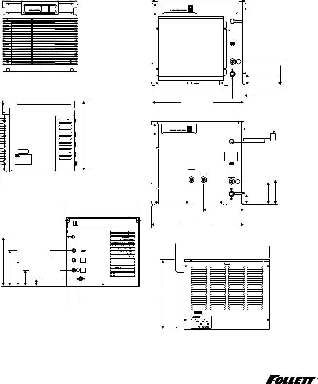
Dimensions and clearances
§§ Entire front of ice machine must be clear of obstructions/connections to allow removal.. §§ 12" (30..5 cm) clearance above ice machine for service..
§§ 6" (15..3 cm) minimum clearance between exhaust side of ice machine and any adjacent equipment..
§§ MCD425A & R425A – 18" (45..7 cm) minimum, 10 ft (3 m) maximum clearance between discharge and air intake grilles..
MCD425A/W_T
MFD425A/W_T
Front view — top mount
Side view — top mount
21.29" (54.1 cm)
 22.49" (57.1 cm)

Back view — top mount
 22.69" (57.6 cm)

 22.46" (57.1 cm)

15.22" (38.7 cm) |
C |
11.03" (28.0 cm) |
E |
8.03" (20.4 cm) |
D |
5.03" (12.8 cm) |
B |
2.34" (6 cm) |
A |
2.32" 
(5.9 cm)

 4.40" (11.2 cm)
MCD425A/W_S
R425A/W
Front view — air-cooled
C
F
B
4.81"  (12.0 cm)
A |
2.31" (5.7 cm) |
2.5" (6.4 cm)  18.88" (48 cm)
Front view — water-cooled
C
F
CONDENSER
OUTLET
D |
E |
B |
4.81" |
|
|
|
|||
|
|
A |
(12.0 cm) |
5.25" |
|
|
2.31" |
(13.3 cm) |
|
|
|
|
(5.7 cm) |
|
|
8.25" (20.9 cm) |
|
|
|
 10.62" (27.0 cm)
 18.88" (48 cm)
Side view — air-cooled and water-cooled
 22.75" (57.8 cm)

 20.75" (52.7 cm)
17.00" (43.2 cm)
 RIDE model air-cooled units only
A – 3/4" MPT drain |
D – 3/8" FPT condenser inlet |
|
B – 3/8" FPT water inlet |
E – 3/8" FPT condenser drain |
|
C – Electrical cord |
F – Bin signal connection (DO NOT APPLY VOLTAGE!) |
|
|
|
|
6 |
MCD425A/W, R425A/W, MFD425A/W, P425A/W Ice Machines |
|

Operation
Cleaning/descaling and sanitizing
Follett ice machines and dispensers, and their associated cleaning and sanitizing procedures, are designed for use with potable water sources.. The presence, or suspected presence, of infectious agents may call for additional measures, including the replacement of components and more comprehensive disinfection measures.. Follett
recommends that these cleaning and sanitizing procedures be reviewed with the appropriate infectious agent subject matter experts to assure complete remediation..
Periodic cleaning/descaling and sanitizing of Follett’s ice machine system is required to ensure peak performance and delivery of clean, sanitary ice.. The recommended cleaning procedures that follow should be performed at least as frequently as recommended and more often if environmental conditions dictate..
Cleaning of the condenser can usually be performed by facility personnel.. Cleaning/descaling and sanitizing of the ice machine system should be performed by your facility’s trained maintenance staff or a Follett authorized
service agent.. Regardless of who performs the cleaning, it is the operator’s responsibility to see that this cleaning is performed according to the schedule below.. Service problems resulting from lack of preventive maintenance will not be covered under the Follett warranty..
Symphony Plus |
Frequency |
Drain Line |
weekly |
|
|
Drain Pan/Drip Pan |
weekly |
|
|
Exterior, Water Station Tube |
as needed |
|
|
Condenser |
monthly (air-cooled only) |
Ice Machine |
semi-annually |
|
|
Transport Tube |
semi-annually |
|
|
* Ice machine must be sanitized prior to start-up..
Weekly
The exterior may be cleaned with a stainless cleaner such as 3M* Stainless Steel Cleaner & Polish or equivalent..
* 3M is a trademark of 3M Company..
Monthly
Condenser (air-cooled ice machine only)
1.Use a vacuum cleaner or stiff brush to carefully clean condenser coils of lint and debris to ensure optimal performance..
2.When reinstalling counter panels in front of RIDE model ice machines, be sure that ventilation louvers line up with condenser air duct..
Semi-Annually (more often if conditions dictate)
§§ A cleaning/descaling and sanitizing procedure should always include both the ice machine and bin/dispenser.. §§ Icemaking system can be cleaned/descaled in place..
Cleaning & Sanitizing Tool Checklist
§§ (2) 1..5 gallon (or larger) plastic buckets §§ (2) clean cloths
§§ Sanitary gloves §§ Safety glasses
§§ (2) Sani-Sponge™ (P/N 00131524 - single sponge)
§§ (1 ) Packet of SafeCLEAN™ (P/N 00132001 - 24 packets)
§§ 1..6 fl oz.. of Nu-Calgon IMS-II or IMS-III Sanitizer (P/N 00979674 - 16 fl.. oz.. bottle)
MCD425A/W, R425A/W, MFD425A/W, P425A/W Ice Machines |
7 |


 CAUTION!
§§ Wear rubber gloves and safety goggles (or face shield) when handling cleaner or sanitizer mixtures.. §§ Use only Follett approved cleaners..
§§ It is a violation of Federal law to use the Cleaning or Sanitizing solution in a manner inconsistent with their labeling..
§§ Do not use solvents, abrasive cleaners, metal scrapers or sharp objects to clean any part of the dispenser..
Cleaning Solution: Mix cleaning solution of 1 gal.. (3..8 L) 100 F (38 C) water and 7 oz.. (198 g) (one 7 oz.. packet) of Follett SafeCLEAN ice machine cleaner/descaler (P/N 00132001)..
Sanitizing Solution: Mix a sanitizing solution of 1 gal.. (3..8 L) 100 F (38 C) water and 1..6 oz.. (47 ml) Nu-Calgon IMS-II or IMS-III Sanitizer (P/N 00979674)..
Cleaning/descaling procedure
Note: Check drains and drain cup to ensure they are open and flowing freely..
1.If ice machine was running recently, ensure that the evaporator is completely free of ice before proceeding..
If there is ice in the evaporator, complete steps 2-7 using only hot water to remove the ice then begin Cleaning/Descaling Procedure again..
2.Remove front or top cover..
3.Disconnect bin signal cable from ice machine electrical box..
4.Press CLEAN switch.. The MAINTENANCE light will turn on and the machine will drain.. Wait for the LOW WATER light to turn on..
5.Remove lid from cleaning cup and fill (about 1 quart) until cleaning solution completely fills the reservoir.. Place lid back on cup..
6.CLEANER FULL light will turn on and machine will start cleaning cycle then rinse three times; this process takes approximately 15 minutes..
7.When machine is finished cleaning, the MAINTENANCE light will turn off..
Sanitizing Procedure
8.Press CLEAN switch.. The MAINTENANCE light and LOW WATER light will turn on..
9.Fill cleaning cup with sanitizing solution until completely fills the reservoir.. Place lid back on cup.. Save remainder of sanitizing solution..
10.CLEANER FULL light will turn on and machine will start sanitizing cycle then rinse three times; this process takes approximately 15 minutes..
11.When machine is finished rinsing, the MAINTENANCE light will turn off.. Remove top bearing insulation and nozzle insulation, then loosen phillips-head screw on nozzle connected to evaporator.. Remove nozzle from evaporator side only, leave other side of nozzle connected to transport tube..
12.Place one Sani-Sponge in remaining sanitizing solution..
13.Insert the sponge soaked in sanitizing solution into nozzle then insert a dry sponge into the nozzle..
14.Replace nozzle onto evaporator and tighten screw.. Ensure drain is connected to reservoir and vent tubes are connected to evaporator drain pan..
15.Reconnect bin signal cable.. Wait for ice to push sponges through transport tube..
16.Collect sponges from ice storage bin..
17.Replace front or top cover..
18.After 10 minutes, dispense all ice and discard..
19.Clean/descale and sanitize dispenser/bin..
User Interface and Exterior Cabinet
§§ Clean stainless steel panels with stainless steel cleaner..
8 MCD425A/W, R425A/W, MFD425A/W, P425A/W Ice Machines
Service
Ice machine Operation (all models)
Follett’s ice machine consists of four distinct functional systems:
§§ Harvesting system §§ Water system
§§ Electrical control system §§ Refrigeration system
These four systems work together to accomplish the production and harvesting of ice.. A problem in any one of these systems will result in improper operation of the entire ice production cycle.. When troubleshooting the ice machine,
it is important to analyze the entire system operation to determine which system is not functioning properly, then pinpoint the component within that system that is malfunctioning.. Determine what corrective action must be taken before making any adjustments or replacing any components..
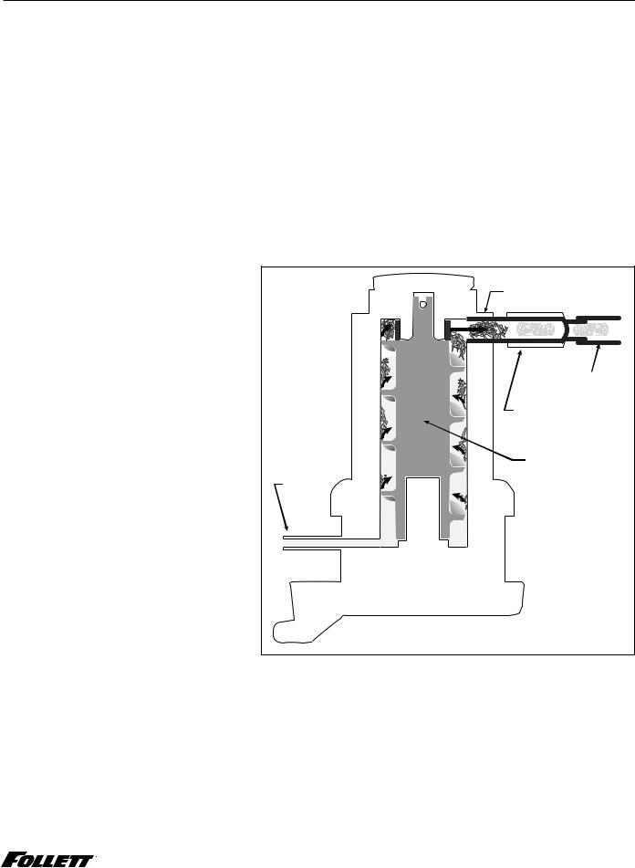
The icemaking process
The Maestro Plus ice machine uses a stainless steel jacketed evaporator and operates on a continuous freezing cycle.. Water is supplied to the evaporator from the water reservoir where the water level is controlled by a float valve.. This valve also shuts off the water supply when the ice machine is not running..
When the ice machine is running, a layer of ice forms on the interior surface of the
evaporator.. This ice is continuously removed by a slowly rotating (12 RPM) auger.. The auger carries the ice upward into the cavity formed by the top bearing housing and the compression loop, where it is compressed to remove excess water.. When the ice reaches the desired hardness it rotates within the cavity and is forced through a discharge port and compression nozzle and into the ice transport tube.. The discharge tube and compression nozzle are slightly restricted to further compress the ice and produce the desired hardness..
A solid state control board located in the electrical box of the ice machine controls the normal operation of the ice machine and monitors gearmotor torque.. This control board will shut down the ice machine should an over-torque condition occur.. It is very important that you familiarize yourself with the operational sequences detailed in this manual before attempting to service the ice machine..
evaporator |
port |
ice transport tube |
compression nozzle |
auger |
water |
inlet |
MCD425A/W, R425A/W, MFD425A/W, P425A/W Ice Machines |
9 |
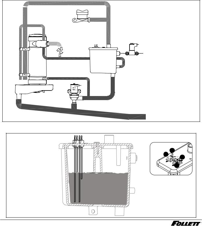
Water system
The water level in the evaporator is controlled by a fill solenoid (Fig 1) and level detecting sensors.. Water sensing rods (Fig. 2) extend down into the reservoir at the end of the evaporator assembly.. The system works via electrical conductivity as follows:
One of the longest probes is a common.. When water is between any of the other probes and the common, the PC board will sense the activation.. During normal operation, the water level rises and falls between the Normal High and Normal Low sensors.. As water is consumed to make ice, the level will fall until the Normal Low sensor is exposed, triggering the water feed solenoid on.. Water will fill until the Normal High sensor is activated..
Note: The potable water dissolved solids content must be greater than 10 ppm for the water control system to function properly.. If using reverse osmosis water filtration system, ensure T..D..S level is greater than 10 ppm..
Fig. 1 Water system diagram
 VENT
VENT
ICE
NOZZLE
EVAPORATOR
CLEANING CUP
|
RESERVOIR FILL |
|
SOLENOID |
WATER |
WATER SUPPLY |
RESERVOIR |
3/8" FPT, 45-90 F (7-32 C) |
|
10-70 PSI (69-483 KPA) |
DRAIN PAN
DRAIN |
WASTE WATER DRAIN |
|
|
|
3/4" FPT |
Fig. 2 Water level diagram
A ALARM LOW (RED)
B COMMON (BLACK)
C NORMAL HIGH (ORANGE) D NORMAL LOW (YELLOW)
A

 B
B


 D
D
C |
C D NORMAL OPERATING RANGE
A B
10 MCD425A/W, R425A/W, MFD425A/W, P425A/W Ice Machines
Electrical system
ATTENTION!
To prevent circuit breaker overload, wait 15 minutes before restarting this unit.This allows the compressor to equalize and the evaporator to thaw.
Normal control board operation
The PC board indicator lights provide all the information necessary to determine the machine's status.. Green indicator lights generally represent “go” or normal operation; Yellow indicators represent normal off conditions; Red indicators generally represent alarm conditions, some of which will lock the machine off..
A flashing green light labeled POWER indicates power to the machine.. All other normal operation status indicators are covered as follows:
Ice machine disposition |
|
|
Operating conditions |
|
Legend: |
ON |
OFF |
ON or OFF |
FLASHING |
1. Ice machine is making ice.. |
|
1. Normal running. |
||
|
|
|
|
|
|
|
|
|
|
|
|
|
|
|
|
|
|
|
|
|
2. Normal time delay. When the bin fills with ice, the LOW BIN |
|
|
|
|
|
|
|
|
|
|
|
|
|
|
|
|
|
|
|
|
|
|
||
|
|
|
|
|
|
|
|
|
|
|
|
|
|
|
|
|
|
|
|
|
||
|
|
|
|
|
|
|
|
|
|
|
|
|
|
|
|
|
|
|
|
|
||
|
|
|
|
|
|
|
|
|
|
|
|
|
|
|
|
|
|
|
|
|
||
2. Ice machine is not making ice.. |
|
|
||||||||||||||||||||
|
|
|
|
|
|
|
|
|
|
|
|
|
|
|
|
|
|
|
|
|
light goes out momentarily and the refrigeration and auger |
|
|
|
|
|
|
|
|
|
|
|
|
|
|
|
|
|
|
|
|
|
|
drive systems immediately shut down.. (Note: The fan motor |
|
|
|
|
|
|
|
|
|
|
|
|
|
|
|
|
|
|
|
|
||||
|
|
|
|
|
|
|
|
|
|
|
|
|
|
|
|
|
|
|
|
|
will continue to run for 10 minutes to cool condenser) The TIME |
|
|
|
|
|
|
|
|
|
|
|
|
|
|
|
|
|
|
|
|
||||
|
|
|
|
|
|
|
|
|
|
|
|
|
|
|
|
|
|
|
||||
|
|
|
|
|
|
|
|
|
|
|
|
|
|
|
|
|
|
|
||||
|
|
|
|
|
|
|
|
|
|
|
|
|
|
|
|
|
|
|
|
|
DELAY light comes on, initiating the time delay period.. When |
|
|
|
|
|
|
|
|
|
|
|
|
|
|
|
|
|
|
|
|
||||
|
|
|
|
|
|
|
|
|
|
|
|
|
|
|
|
|
|
|
|
|
the time delay expires, the machine will restart provided that the |
|
|
|
|
|
|
|
|
|
|
|
|
|
|
|
|
|
|
|
|
|
|
LOW BIN light is on.. |
|
DIP Switch Settings |
|
|
|
|
||||||||||||||||||
|
|
|
|
|
|
|
|
|
|
|
|
|
|
|
||||||||
|
|
|
|
|
|
|
|
|
|
OFF POSITION |
|
|
ON POSITION |
|||||||||
|
|
|
|
|
|
|
|
|
|
|
|
|||||||||||
|
|
|
|
|
|
|
|
|
|
|
|
|
|
|
|
|
|
|
|
|
|
|
MCD425A/W_T, MCD425A/W_S, R425A/W
Sleep cycle disabled Not used Sleep cycle
dispense duration 20 min. time delay Flush disabled Maint. timer ON
OFF ON


 8 7 6 5 4 3 2 1
Sleep cycle enabled Not used Sleep cycle
dispense duration 60 min. time delay Flush enabled Maint. timer OFF
425A/W installed in Symphony Plus 25/50/110 CI, CT, or FB
OFF ON
Sleep cycle disabled Not used Sleep cycle
dispense duration 20 min. time delay Flush disabled Maint. timer ON


 8 7 6 5 4 3 2 1
Sleep cycle enabled Not used Sleep cycle
dispense duration 60 min. time delay Flush enabled Maint. timer OFF
Replacement P425A/W installed in Symphony dispenser OFF ON
Sleep cycle disabled Not used Sleep cycle
dispense duration 20 min. time delay Flush disabled Maint. timer ON
 8 7 6 5 4 3 2 1
Sleep cycle
enabled
Not used Sleep cycle
dispense duration
60 min. time delay Flush enabled* Maint. timer OFF
Sleep cycle dispense duration
OFF |
4 |
|
1 |
|
35 s |
2 |
5 |
|
3 |
|
|
4 |
|
|
5 |
|
|
6 |
4 |
15 s |
7 |
|
|
8 |
5 |
|
|
|
|
4 |
5 s |
|
5 |
||
|
||
4 |
60 s |
|
5 |
||
|
*Flush can be enabled on Symphony CT and FB models. Flush should be disabled on Symphony CI units due to risk of internal leak if drain line is blocked. All Symphony Plus models should be set to Flush enabled.
MCD425A/W, R425A/W, MFD425A/W, P425A/W Ice Machines |
11 |

Relay/triac output indication
Each relay on the board has an indicator light associated with its output.. For example, when the relay for the water feed solenoid is energized, the adjacent indicator light glows green..
Flushing logic
Off cycle: At the completion of off-cycle time delay, the machine checks for a cumulative one (1) hour of ice making time since the last off-cycle flush.. If the cumulative ice making time exceeds one (1) hour, the machine will open the drain valve for 60 seconds to drain the evaporator in its entirety.. It will then refill with water, flush again and refill, and begin making ice.. If the ice making time is less than 1 hour, the machine will start and begin making ice without draining the evaporator..
Error faults
The Maestro Plus PC board monitors various operating parameters including high pressure, auger gearmotor amperage limits, clogged drain, and low water alarm conditions.. There are two types of errors namely “hard” or “soft”.. A hard error is one that shuts the machine off and will not allow restart until the reset button is pressed.. Even cycling power will not reset a hard error.. A soft error can either be automatically reset should the condition rectify, or if power is cycled.. Should an error occur, consult the troubleshooting guide in this manual or a Follett service technician..
Soft errors:
Note: For all soft errors, the ice machine will remain off for 1 hour..
LO WATER: During operation, the water level cycles between the normal low and normal high sensors.. Should the water be shut off to a running machine, a soft error will occur.. The error sequence is as follows: During operation, the water level falls to the normal low sensor, and when it does the water feed solenoid is energized.. If water is not detected at the normal low sensor within 10 seconds, a soft error will occur.. The machine will shut down and TIME DELAY and LOW WATER LEDs will be lit.. After time delay, the solenoid will energize and remain energized until the water level is sufficient for restart..
HI PRESSURE: Should the refrigeration pressure rise above 425 psi, the machine will shut down and the TIME DELAY and HIGH PRESSURE will be illuminated.. After the time delay, and if the pressure has fallen back below the reset point of 295 psi, the machine will restart and the TIME DELAY and HIGH PRESSURE will clear..
HI AMPS: The PC board monitors the amperage of the auger motor.. Should the gear motor experience current draw above the allowable 3A limit or no current draw (0A), the machine will shut down and the TIME DELAY and HI AMP will be illuminated.. After the time delay the machine will restart and the TIME DELAY and HI AMP will clear..
Hard error:
HI AMPS: If a second hi-amp error occurs within 1 hour of the initial hi-amp error, the ice machine will shut off and the reset on the board must be pressed to clear the error.. If a second hi-amp has occurred, the HI AMP LED only will be illuminated..
DRAIN CLOG: The drain clog sensor, located in the evaporator drain pan will detect the presence of water just below the top edge of the pan.. If water does not properly flow out of the internal or external drain lines it will backup into the drain pan (especially during a self-flushing purge cycle).. Pressing the reset button will restart the ice machine..
12 MCD425A/W, R425A/W, MFD425A/W, P425A/W Ice Machines
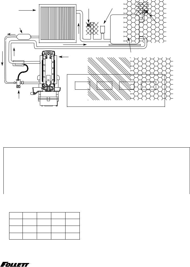
Technical specifications (all models)
Refrigeration system diagram
high side |
high pressure |
service port |
switch |
condenser
filter dryer |
low side |
service port
evaporator |
compressor |
|
|
high |
high |
low |
low |
thermostatic |
pressure |
pressure |
pressure |
pressure |
vapor |
liquid |
liquid |
vapor |
|
expansion |
|
|
|
|
valve |
|
|
|
|
Refrigeration pressure data
§§ Water regulating valve is factory set at 300 (±10) PSIG head pressure.. §§ Readings within 10% of table values should be considered normal..
Compressor data
Locked rotor amps 58. 8A.
Compressor current draw
Air-cooled
Ambient air temperature |
60 F/15..6 C |
70 F/21..1 C |
80 F/26..7 C |
90 F/32..2 C |
100 F/37..8 C |
Amperage |
6..3A |
6..5A |
6..7A |
6..9A |
7..1A |
|
|
|
|
|
|
High-side pressure (psi) |
190 |
220 |
250 |
290 |
330 |
|
|
|
|
|
|
Low-side pressure (psi) |
27 |
29 |
31 |
33 |
36 |
|
|
|
|
|
|
Water-cooled |
|
|
|
|
|
Water temperature at float |
50 F/10 C |
60 F/15..6 C |
70 F/21..1 C |
80 F/26..7 C |
90 F/32..2 C |
|
|
|
|
|
|
|
5..6A |
5..6A |
5..7A |
5..8A |
5..8A |
|
|
|
|
|
|
Ice machine inlet water temperature ˚F/˚C
Water-cooled Ice Machine Refrigeration Pressure
Discharge Pressure/Suction Pressure Condenser inlet water temperature ˚F/˚C
˚F/˚C 50/10 70/21 90/32
50/10 280/27 285/29 290/31 psi
70/21 280/27 285/29 290/31 psi
90/32 280/27 285/29 290/31 psi
Gearmotor data |
Split-Phase |
PSC (permanent split capacitor) |
Gearmotor current |
1..8A-1..9A (nominal) |
0..8A-0..9A (nominal) |
Locked rotor amps |
14A |
7A-14A (temperature dependent) |
MCD425A/W, R425A/W, MFD425A/W, P425A/W Ice Machines |
13 |
Air-Cooled ice machine capacity/24hrs.
Ambient Air Temperature F/C
|
F |
60 |
70 |
80 |
90 |
100 |
|
|
|
|
|
|
|
|
|
|
|
|
C |
16 |
21 |
27 |
32 |
38 |
|
|
|
|
|
|
|
|
|
|
|
|
50 |
460 |
425 |
390 |
355 |
320 |
lbs.. |
|
|
|
|
|
|
|
|
|
|
F/C |
10 |
208 |
193 |
177 |
161 |
145 |
kg.. |
|
|
|
|
|
|
|
|
||
60 |
437..5 |
405 |
372..5 |
340 |
307..5 |
lbs.. |
||
Temperature |
||||||||
|
|
|
|
|
|
|
||
16 |
198 |
184 |
169 |
154 |
139 |
kg.. |
||
|
||||||||
|
70 |
415 |
385 |
355 |
325 |
295 |
lbs.. |
|
|
|
|
|
|
|
|
|
|
|
21 |
188 |
175 |
161 |
147 |
134 |
kg.. |
|
|
|
|
|
|
|
|
|
|
Water |
80 |
405 |
375 |
345 |
315 |
285 |
lbs.. |
|
|
|
|
|
|
|
|
||
27 |
184 |
170 |
156 |
142 |
129 |
kg.. |
||
|
||||||||
Inlet |
90 |
395 |
365 |
335 |
305 |
275 |
lbs.. |
|
32 |
179 |
166 |
152 |
138 |
125 |
kg.. |
||
|
|
|
|
|
|
|
|
Water-Cooled ice machine capacity/24hrs.
Condenser Water Temperature F/C
|
F |
50 |
60 |
70 |
80 |
90 |
100 |
|
|
|
|
|
|
|
|
|
|
|
|
|
C |
10 |
16 |
21 |
27 |
32 |
38 |
|
|
|
|
|
|
|
|
|
|
|
|
|
50 |
486 |
465 |
443 |
422 |
400 |
389 |
lbs.. |
|
F/C |
10 |
220 |
211 |
201 |
191 |
181 |
176 |
kg.. |
|
|
|
|
|
|
|
|
|
||
60 |
464 |
445 |
425 |
406 |
386 |
367 |
lbs.. |
||
Temperature |
|||||||||
|
|
|
|
|
|
|
|
||
16 |
210 |
202 |
193 |
184 |
175 |
166 |
kg.. |
||
|
|||||||||
|
|
|
|
|
|
|
|
|
|
|
70 |
443 |
425 |
408 |
390 |
372 |
358 |
lbs.. |
|
|
21 |
201 |
193 |
185 |
177 |
169 |
162 |
kg.. |
|
|
|
|
|
|
|
|
|
|
|
Water |
80 |
422 |
406 |
389 |
373 |
356 |
340 |
lbs.. |
|
|
|
|
|
|
|
|
|
||
27 |
191 |
184 |
176 |
169 |
161 |
154 |
kg.. |
||
|
|||||||||
|
|
|
|
|
|
|
|
|
|
Inlet |
90 |
400 |
385 |
371 |
356 |
341 |
326 |
lbs.. |
|
32 |
181 |
175 |
168 |
161 |
155 |
148 |
kg.. |
||
|
|
|
|
|
|
|
|
|
Note: Nominal values - actual production may vary by ±10%..
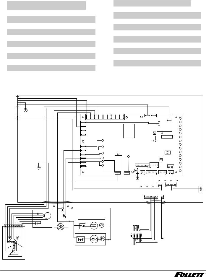
Electrical control system schematic
|
|
|
L1 |
|
|
|
|
BLACK #26 |
|
|
|
|
|
|
|
|
|
|
|
|
|
|
|
|
|
|
|
|
|
|
|
|
|
|
|
|
|
|
|
|
WHITE #25 |
|
|
|
|
|
|
|
|
|
|
|
|
|
|
|
|
|
|
|
|
|
|
|
|
||
|
|
|
L2/N |
|
|
|
|
|
|
|
|
|
|
|
|
|
|
|
|
|
|
|
|
|
|
|
|
|
|
|
|||
|
|
|
|
|
|
GRN-YEL #24 |
|
|
|
|
|
|
|
|
|
|
|
|
|
|
|
|
|
|
|
|
|
|
|
|
|||
|
|
|
GND |
|
|
|
|
|
|
|
|
|
|
|
|
|
|
|
|
|
|
|
|
|
|
|
|
|
|
|
|||
|
|
|
|
|
|
BLACK #23 |
|
|
|
|
|
|
|
|
|
|
|
|
|
|
|
|
|
BLACK #23 |
|
|
|
|
|
|
|||
|
|
|
DISP |
|
|
|
|
|
|
|
|
|
|
|
|
|
|
|
|
|
|
|
|
|
|
|
|
|
|
||||
|
|
|
|
|
|
|
|
|
|
|
|
|
|
|
|
|
|
|
|
|
|
|
|
|
|
BLACK #51 |
|
|
|
||||
|
|
|
|
|
|
|
|
|
|
|
|
|
|
|
|
|
|
|
|
|
|
|
|
|
|
|
|
|
|
|
|
||
|
|
BIN |
|
|
|
|
|
|
|
|
|
|
|
|
|
P2 |
|
|
|
|
|
|
|
|
|
|
|
|
|
|
|
|
|
|
|
CONTACT |
|
|
|
|
|
|
|
|
|
|
|
|
N |
N |
N |
N |
N |
N |
N |
N |
N |
ICE AUX |
WATER AUX |
|
|
COMPRESSOR |
D1 |
POWER |
|||
|
|
CLOSURE |
|
|
|
|
|
|
|
|
|
|
|
|
|
|
|
|
|
|
|
|
|
|
|
|
|||||||
|
|
|
|
|
|
|
|
|
|
|
|
|
|
|
|
|
|
|
|
|
|
|
P15 |
P16 |
|
|
|
||||||
|
|
|
|
|
|
|
|
|
|
|
|
|
|
|
|
|
|
|
|
|
|
|
|
|
|
|
|
|
|
|
D2 |
LOW BIN |
|
|
|
|
|
|
|
|
|
|
|
|
|
|
|
|
|
|
L1 |
|
|
|
|
|
BLACK #01 |
|
T1 |
|
|
|
|
|
|||
|
|
|
|
|
|
|
|
|
|
|
|
|
|
|
|
|
|
|
|
|
|
|
|
|
|
|
D3 |
|
|||||
|
|
|
|
|
|
|
|
|
|
|
|
|
|
|
|
|
|
|
|
|
|
|
|
|
|
|
|
|
|
MAKING ICE |
|||
|
|
|
|
|
|
|
|
|
|
|
|
|
|
|
|
|
|
|
|
|
|
|
|
|
|
|
|
|
|
|
|
||
|
|
|
|
|
|
|
|
|
|
|
|
|
|
|
|
|
|
|
|
|
|
|
|
|
|
|
|
|
|
|
|
|
|
|
|
|
|
|
|
|
|
|
|
|
|
|
|
|
|
|
L1 |
|
|
|
|
|
|
|
|
|
|
|
|
|
|
D4 |
SLEEP CYCLE |
|
|
|
|
|
|
|
|
|
|
|
|
|
|
|
|
|
|
|
|
|
|
|
|
|
|
|
|
HI PRS |
|
|
|
|
|
|
|
|
|
|
|
|
|
|
|
|
|
|
|
|
|
|
L1 |
|
|
|
|
|
|
|
|
|
|
P14 |
D16 |
|
K1 |
D5 |
TIME DELAY |
|
|
|
|
|
|
|
|
|
|
|
|
|
|
|
|
|
|
|
|
|
|
|
|
|
|
|
|
|
|
||||
|
|
|
|
|
|
|
|
|
|
|
|
|
|
|
|
|
|
|
|
|
|
|
|
|
|
|
|
|
|
|
S1 |
|
|
|
|
|
|
|
|
|
|
|
|
|
|
|
|
|
|
P1 |
|
|
|
|
|
|
|
|
|
|
|
|
|
|
D6 |
LOW WATER |
|
|
|
|
|
|
|
|
|
|
|
|
|
|
|
|
|
|
|
|
|
|
|
|
|
|
|
|
|
|
|
|
|||
|
|
|
|
|
|
|
|
|
|
|
|
|
|
|
|
|
|
|
|
|
|
|
|
|
|
|
|
|
|
|
|
||
|
|
|
|
|
|
|
|
|
|
|
|
|
|
|
|
|
|
|
|
|
|
|
|
|
|
|
|
|
|
|
|
|
|
|
|
|
|
|
|
|
|
|
|
|
|
|
|
|
|
|
|
|
|
|
D19 |
|
|
|
|
|
|
|
|
MODEL SELECT |
D7 |
MAINTENANCE |
|
|
|
|
|
|
|
|
|
|
|
|
|
|
|
|
|
|
|
|
|
|
|
|
|
|
|
|
|
|
|
||||
|
|
|
|
|
|
|
|
|
|
|
|
|
|
|
|
|
|
|
|
|
|
|
|
|
|
|
|
|
|
|
|
|
|
|
|
|
|
|
|
|
|
|
|
|
|
|
|
|
|
|
P6 |
|
|
|
|
|
|
|
|
|
|
|
|
|
|
D8 |
SERVICE |
|
|
|
|
|
|
|
|
|
|
|
|
|
|
|
|
|
|
|
|
|
|
|
|
|
|
|
|
|
|
|
|
||
|
|
|
|
|
|
|
|
|
|
|
|
|
|
|
|
|
|
|
|
|
D22 |
|
|
|
|
|
|
|
|
|
|
|
|
|
|
|
|
|
|
|
|
|
|
|
|
|
|
|
|
|
P21 |
|
|
|
|
|
|
|
|
|
|
|
|
|
D9 |
HI AMPS |
|
|
|
|
|
|
|
|
|
|
|
|
|
|
|
|
|
|
|
|
|
|
|
|
|
|
|
|
|
|
P9 |
|
|
||
|
|
|
|
|
|
|
|
|
|
|
|
|
|
|
|
|
|
|
|
|
|
|
|
|
|
|
|
|
|
2 |
6 |
D10 |
HI PRESSURE |
|
|
|
|
|
|
|
|
|
|
|
|
|
|
|
|
|
P20 |
|
|
|
D21 |
|
|
|
|
D18 |
|
|
|
|
|||
|
|
|
|
|
|
|
|
|
|
|
|
|
|
|
|
|
|
|
|
|
|
|
K3 |
|
|
|
|
|
1 |
5 |
D11 |
DRAIN CLOG |
|
|
|
|
|
|
|
|
|
|
|
|
|
|
|
|
|
|
P19 |
|
|
|
|
|
|
|
D37 |
|
|
|
PROGRAM |
||||
|
|
|
|
|
|
|
|
|
|
|
|
|
|
|
|
|
|
|
|
D20 |
|
|
|
|
|
|
|
|
|
|
|
||
|
|
|
|
|
|
|
|
|
|
|
|
|
|
|
|
|
|
|
|
|
CURRENT SENS |
|
|
|
|
S2 |
RESET |
|
D12 |
CLEANER FULL |
|||
|
|
|
|
|
|
|
|
|
|
|
|
|
|
|
|
|
P3 |
|
|
|
|
|
|
|
P10 |
|
|
||||||
|
|
|
|
|
|
|
|
|
|
|
|
|
|
|
|
|
|
|
|
D17 |
|
|
|
|
|
P17 |
SERIAL COMM |
|
|
D13 |
|
||
|
|
|
|
|
|
|
|
|
|
|
|
|
|
|
|
|
|
|
|
|
|
|
|
|
|
WATER LEVELS |
|
|
|
|
|
||
|
|
|
|
|
|
|
|
|
|
|
|
|
|
|
|
|
|
|
|
|
|
|
|
|
|
|
|
|
RS485 UI |
|
|
||
|
|
|
|
|
|
|
|
|
|
|
|
|
|
|
|
|
P22 |
|
|
|
|
|
|
|
|
|
|
|
|
P7 |
|
|
|
|
|
|
|
|
|
|
|
|
|
|
|
|
|
|
|
|
|
|
|
|
|
|
|
|
|
|
|
|
|
D14 |
|
||
|
|
|
|
|
|
|
|
|
|
|
|
|
|
|
|
|
|
|
|
|
|
|
|
|
|
|
|
|
|
|
|
||
|
|
|
|
|
|
|
|
|
|
|
|
|
|
|
|
|
|
|
|
|
D48 |
|
|
|
|
|
|
|
|
|
|
|
|
|
|
|
|
|
|
|
|
|
|
|
|
|
|
|
|
|
|
|
|
|
|
|
|
|
|
P5 |
P12 BIN P11 |
|
P13 |
|
P8 RS485 |
D15 |
|
|
|
|
|
|
|
|
|
|
|
|
|
|
|
|
|
|
|
|
|
|
|
|
|
|
|
|
|
|
|
|
|
|
|
|
|
|
|
|
|
|
|
|
|
|
|
|
|
|
|
|
|
|
|
|
|
|
T2 |
AUGER |
|
P4 |
P18 |
|
|
|
|
|
|
|
|
|
|
|
|
|
|
|
|
|
|
|
|
|
|
|
|
|
|
|
|
|
|
|
|
|
|
|
|
|
|
|
|
|
|
|
|
|
|
|
|
|
|
|
|
|
|
|
|
|
|
|
|
|
|
|
|
|
|
GRN #17 |
|
|
|
|
|
|
|
|
|
|
|
|
|
|
|
|
|
|
|
|
|
|
|
|
|
|
|
|
|
|
|
|
|
|
|
|
P12 BIN |
P11 |
CLEAN SAFE |
|
MAINT. |
|
|
|
|
|
|
|
|
|
|
|
|
|
|
|
|
|
|
|
|
|
|
|
|
|
|
|
|
|
|
|
|
|
|
|
|
|
|
|
|
|
|
|
|
|
|
|
|
|
|
|
|
|
|
|
|
|
|
|
|
|
|
|
|
|
|
|
CLEAN |
|
|
|
|
|
|
|
|
|
BLACK #51 |
WHITE #52 GREEN #53 |
WHITE #121 |
WHITE #13 |
RED #16 BROWN #14 |
BLACK #122 |
BLUE #07 |
|
|
|
|
|
|
|
|
|
|
|
|
P17 |
|
|
|
|
|
|
|
|
|
|
|
|
|
|
|
|
|
|
|
|
|
|
|
|
|
WATER LEVELS |
HI PRS |
|
|
|
|||||||||
|
|
|
|
|
|
|
|
|
|
|
|
|
|
|
|
|
|
|
|
|
|
P14 |
|
|
|
|
|||||||
|
|
|
|
|
|
|
|
|
|
|
|
|
|
|
|
|
|
|
|
|
|
|
|
|
|
|
|||||||
|
|
|
|
|
|
|
|
|
|
|
BLACK |
|
|
|
BLUE |
|
|
|
|
|
|
|
|
|
|
|
|
|
|
|
|
|
|
|
|
|
|
|
|
|
|
|
|
|
|
#15 |
|
|
|
|
|
|
|
|
|
|
|
|
|
|
|
|
|
|
|
|
|
|
|
|
|
|
|
|
|
|
O.L. |
|
WHITE |
FEED VALVE |
BLACK |
|
|
|
|
|
|
|
|
|
|
|
|
|
|
|
|
|
|
|
|
|
|
|
|
|
|
|
|
|
C |
|
|
|
|
|
|
|
|
|
|
|
|
|
|
|
|
|
|
|
|
||||
|
|
|
|
|
|
|
|
|
|
|
|
|
|
|
|
|
|
|
|
|
|
|
|
|
|
|
|
|
|
||||
|
|
|
|
ORANGE #55 |
|
|
|
|
S |
COMP. |
#04 |
|
|
|
|
|
|
|
|
|
|
|
|
|
|
|
|
|
|
|
|||
BLACK #51 |
WHITE #52 |
GREEN#53 |
|
BLACK #56 |
|
|
|
R |
|
|
|
|
|
|
|
|
|
|
|
|
|
|
|
|
|
|
|
|
|
|
|
|
|
RED #54 |
|
|
|
GREEN #57 |
|
|
|
DRAIN VALVE |
|
|
|
|
|
|
|
|
|
|
|
|
|
|
|
|
|
|
|
||||||
|
|
|
BLACK #58 |
|
|
|
#05 |
|
WHITE |
START |
|
SPLIT-PHASE |
|
|
|
|
|
|
|
|
|
|
|
|
|||||||||
|
|
|
BLACK #59 |
|
|
|
|
|
|
RELAY |
|
START |
|
|
|
|
|
|
|
|
|
|
|
|
|
|
|||||||
1 |
2 |
3 |
4 |
5 |
6 |
7 |
8 |
9 |
|
|
|
|
|
|
|
4 |
2 |
BLACK |
|
|
|
|
|
|
|
|
|
|
|
|
|
|
|
C2 START |
|
|
|
|
|
|
|
|
|
|
|
|
|
|
|
DRAIN CLOG |
|
|
|
|
|
|
|
||||||||||
|
|
|
|
|
|
|
|
|
|
|
|
|
|
|
|
|
YELLOW |
|
|
|
|
|
|
|
|
|
|
|
|
|
|
||
|
|
|
|
|
|
|
|
|
COMPRESSOR |
|
|
|
|
|
|
3 |
RUN |
|
T.O.L. |
|
|
|
|
VIOLET |
|
|
|
|
|
|
|||
BLACK #61 |
WHITE#62 |
GREEN #63 |
WHITE#64 |
BLACK #65 |
BLACK #66 |
GREEN #67 |
BLACK #68 |
BLACK #69 |
|
|
|
|
|
|
|
|
|
|
|
|
|
|
|
SENSOR |
|
|
|
|
|
|
|||
|
|
|
|
FAN |
|
|
|
|
|
PSC MOTOR OR |
|
|
|
BLACK |
|
|
|
|
|
|
|||||||||||||
|
|
|
|
|
|
|
|
|
|
|
RESERVOIR A B C D |
|
|
|
|
|
|
||||||||||||||||
|
|
|
|
|
|
|
CAPACITOR |
|
|
|
|
|
|
|
|
|
|||||||||||||||||
|
|
|
|
|
|
|
|
|
|
|
|
|
|
|
|
|
BLACK |
START |
|
|
|
BLUE |
|
WATER SENSOR |
RED |
|
|
|
|
|
|
||
|
|
|
|
|
|
|
|
|
COMPRESSOR |
|
|
|
|
|
|
|
|
|
|
|
|
|
|
|
P |
|
|
|
|||||
|
|
|
|
|
|
|
|
|
|
|
|
|
|
|
|
|
|
|
|
|
|
|
|
|
|
|
|
|
|||||
|
|
|
|
|
|
|
|
|
|
|
|
|
|
|
|
|
|
|
|
|
|
|
|
|
|
ORANGE |
|
HIGH |
|
|
|
||
|
|
|
|
|
|
|
|
|
ELECTRICAL |
|
|
|
|
|
|
|
|
|
RUN |
|
|
|
|
|
|
|
YELLOW |
|
|
|
|||
|
|
5 |
|
2 |
|
|
|
|
BOX |
|
|
|
|
|
|
|
YELLOW |
|
T.O.L. |
|
|
|
|
|
BLACK |
PRESS |
|
|
|
||||
|
|
|
|
|
|
|
|
|
|
|
|
|
|
|
|
|
|
|
|
|
|
|
|
||||||||||
|
|
|
|
|
|
|
|
|
|
|
|
|
|
|
|
|
|
|
|
|
|
|
|
|
|
|
|||||||
|
|
|
6 |
|
|
|
|
|
BLACK #71 |
|
|
|
|
|
|
|
|
|
|
|
|
|
|
|
|
|
|
|
|
|
|
|
|
|
|
4 |
|
1 |
|
|
|
|
|
|
|
|
|
|
|
|
|
|
|
|
|
|
|
|
|
|
|
|
|
|
|
|
|
|
|
|
|
|
|
|
|
|
|
|
|
|
|
|
|
|
|
|
|
|
|
|
|
|
|
|
|
|
|
|
|
||
|
|
|
|
C1 RUN |
|
|
|
|
|
|
|
|
|
|
|
|
|
|
|
|
|
|
|
|
|
|
|
|
|
|
|
|
|
|
|
|
BLACK #66 |
|
|
|
|
|
|
|
|
|
|
|
|
|
|
|
|
|
|
|
|
|
|
|
|
|
|
|
|||
|
|
|
BLACK #69 |
|
|
|
|
|
|
|
|
|
|
|
|
|
|
|
|
|
|
|
|
|
|
|
|
|
|
|
|||
14 |
|
|
|
|
MCD425A/W, R425A/W, MFD425A/W, P425A/W Ice Machines |
|
|
|
|
|
|
|
|||||||||||||||||||||
 Loading...