


Follett HCF2110RBS, HCF2110RHT, HCD2110NBS, HCF2110RBT, HCD2110NBT User Manual
...HC_1810R/N, HC_2110R/N, HM_1810R/N, HM_2110R/N
Horizon Elite™ Ice Machines (Remote Condensing)
Order parts online www.follettice.com
Operation and Service Manual
Following installation, please forward this manual to the appropriate operations person.
801 Church Lane • Easton, PA 18040, USA |
|
Toll free (877) 612-5086 • +1 (610) 252-7301 |
01157841R04 |
HC_1810R/N, HC_2110R/N, HM_1810R/N, HM_2110R/N |
|
www.follettice.com |
|
2 |
HC_1810R/N, HC_2110R/N, HM_1810R/N, HM_2110R/N |
Contents
Welcome to Follett. . . . . . . . . . . . . . . . . . . . . . . . . . . . . . . . . . . . . . . . . . . . . . . . . . . . . . . . . . . . . . . . . . . . . . . . . . . . . . |
4 |
Before you begin.. . . . . . . . . . . . . . . . . . . . . . . . . . . . . . . . . . . . . . . |
4 |
Specifications. . . . . . . . . . . . . . . . . . . . . . . . . . . . . . . . . . . . . . . . . |
5 |
Electrical.. . . . . . . . . . . . . . . . . . . . . . . . . . . . . . . . . . . . . . . . . . . . . . . . . . . . . . . . . . . . . . . . . . . . . . . . . . . . . . . . . . . |
5 |
Evaporator unit.. . . . . . . . . . . . . . . . . . . . . . . . . . . . . . . . . . . . . . . . . . . . . . . . . . . . . . . . . . . . . . . . . . . . . . . . . . . . . . |
5 |
Condensing unit. . . . . . . . . . . . . . . . . . . . . . . . . . . . . . . . . . . . . . . . . . . . . . . . . . . . . . . . . . . . . . . . . . . . . . . . . . . . . . |
5 |
Evaporator plumbing. . . . . . . . . . . . . . . . . . . . . . . . . . . . . . . . . . . . . . . . . . . . . . . . . . . . . . . . . . . . . . . . . . . . . . . . . . |
5 |
Flush drain plumbing . . . . . . . . . . . . . . . . . . . . . . . . . . . . . . . . . . . . . . . . . . . . . . . . . . . . . . . . . . . . . . . . . . . . . . . . . . |
5 |
Ambient. . . . . . . . . . . . . . . . . . . . . . . . . . . . . . . . . . . . . . . . . . . . . . . . . . . . . . . . . . . . . . . . . . . . . . . . . . . . . . . . . . . . |
6 |
Refrigeration.. . . . . . . . . . . . . . . . . . . . . . . . . . . . . . . . . . . . . . . . . . . . . . . . . . . . . . . . . . . . . . . . . . . . . . . . . . . . . . . . |
6 |
Weight. . . . . . . . . . . . . . . . . . . . . . . . . . . . . . . . . . . . . . . . . . . . . . . . . . . . . . . . . . . . . . . . . . . . . . . . . . . . . . . . . . . . . |
6 |
Ice production.. . . . . . . . . . . . . . . . . . . . . . . . . . . . . . . . . . . . . . . . . . . . . . . . . . . . . . . . . . . . . . . . . . . . . . . . . . . . . . . |
6 |
Dimensions and clearances.. . . . . . . . . . . . . . . . . . . . . . . . . . . . . . . . . . . . . . . . . . . . . . . . . . . . . . . . . . . . . . . . . . . . |
7 |
Operation. . . . . . . . . . . . . . . . . . . . . . . . . . . . . . . . . . . . . . . . . . |
. |
9 |
||
Cleaning/sanitizing and preventive maintenance (all models).. . . . . . . . . . . . . . . . . . . . . . . . . . . . . . . . . . . . . . . . . . |
|
9 |
||
Service. . . . . . . . . . . . . . . . . . . . . . . . . . . . . . . . . . . . . . . . . . . |
. |
13 |
||
Ice machine operation (all models) . . . . . . . . . . . . . . . . . . . . . . . . . . . . . . . . . . . . . . . . . . . . . . . . . . . . . . . . . . . . . . |
|
13 |
||
Water system. . |
. . . . . . . . . . . . . . . . . . . . . . . . . . . . . . . . . . . . . . . |
|
14 |
|
“Bin full” detection system. . . . . . . . . . . . . . . . . . . . . . . . . . . . . . . . . . . . . . . . . . . . . . . . . . . . . . . . . . . . . . . . . . . . . |
|
15 |
||
Electrical system. . . . . |
. . . . . . . . . . . . . . . . . . . . . . . . . . . . . . . . . . . . . . . . . . . . . . . . . . . . . . . . . . . . . . . . . . . . . . . |
|
16 |
|
Mechanical System. . |
. . . . . . . . . . . . . . . . . . . . . . . . . . . . . . . . . . . . |
. 21 |
||
Evaporator disassembly. . . . . . . . . . . . . . . . . . . . . . . . . . . . . . . . . . . . . . . . . . . . . . . . . . . . . . . . . . . . . . . . . . . . . . . |
|
21 |
||
Evaporator reassembly. . . . . . . . . . . . . . . . . . . . . . . . . . . . . . . . . . . . . . . . . . . . . . . . . . . . . . . . . . . . . . . . . . . . . . . |
|
24 |
||
Refrigeration system. |
. . . . . . . . . . . . . . . . . . . . . . . . . . . . . . . . . . . . . . . . . . . . . . . . . . . . . . . . . . . . . . . . . . . . . . . . |
|
29 |
|
Troubleshooting . . . . . . . . . . . . . . . . . . . . . . . . . . . . . . . . . . . . . . . |
. 32 |
|||
Replacement parts. . . . . . . . . . . . . . . . . . . . . . . . . . . . . . . . . . . . . . . 34
Evaporator assembly . . . . . . . . . . . . . . . . . . . . . . . . . . . . . . . . . . . . . . . . . . . . . . . . . . . . . . . . . . . . . . . . . . . . . . . . . |
34 |
|
Low-side assembly.. . . . . . . . . . . . . . . . . . . . . . . . . . . . . . . . . . . . . . . . . . . . . . . . . . . . . . . . . . . . . . . . . . . . . . . . . . |
36 |
|
Electrical box . . . . . . . . . . . . . . . . . . . . . . . . . . . . . . . . . . . . . . . . . . . . . . . . . . . . . . . . . . . . . . . . . . . . . . . . . . . . . . . |
38 |
|
Integration kit – top-mount and RIDE remote ice delivery . . . . . . . . . . . . . . . . . . . . . . . . . . . . . . . . . . . . . . . . . . . . |
40 |
|
Skins assembly. . . . . . . . . . . . . . . . . . . . . . . . . . . . . . . . . . . . . . . . . . . . . . . . . . . . . . . . . . . . . . . . . . . . . . . . . . . . . |
42 |
|
1810 |
Single-phase condensing unit.. . . . . . . . . . . . . . . . . . . . . . . . . . . . . . . . . . . . . . . . . . . . . . . . . . . . . . . . . . . . . |
44 |
2110 |
Single-phase condensing unit. . . . . . . . . . . . . . . . . . . . . . . . . . . . . . . . . . . . . . . . . . . . . . . . . . . . . . . . . . . . . . |
45 |
1810 |
3-phase condensing unit.. . . . . . . . . . . . . . . . . . . . . . . . . . . . . . . . . . . . . . . . . . . . . . . . . . . . . . . . . . . . . . . . . |
46 |
2110 |
3-phase condensing unit. . . . . . . . . . . . . . . . . . . . . . . . . . . . . . . . . . . . . . . . . . . . . . . . . . . . . . . . . . . . . . . . . . |
47 |
HC_1810R/N, HC_2110R/N, HM_1810R/N, HM_2110R/N |
3 |

Welcome to Follett
Follett equipment enjoys a well-deserved reputation for excellent performance, long-term reliability and outstanding after-the-sale support. To ensure that this equipment delivers the same degree of service, we ask that you review the installation manual (provided as a separate document) before beginning to install the unit. Our instructions are designed to help you achieve a trouble-free installation. Should you have any questions or require technical help at any time, please call our technical service group at (877) 612-5086 or +1 (610) 2527301.
Before you begin
After uncrating and removing all packing material, inspect the equipment for concealed shipping damage. If damage is found, notify the shipper immediately and contact Follett LLC so that we can help in the filing of a claim, if necessary.
Check your paperwork to determine which model you have. Follett model numbers are designed to provide information about the type and capacity of Follett equipment. Following is an explanation of the different model numbers in the series.
|
|
|
|
|
Chewblet® Ice Machine Model Number Configurations |
|
|
|
|
|
|
|||||||||||||||||||||
|
|
|
|
|
|
|
|
|
|
|
|
|
|
|
|
|
|
|
|
|
|
|
|
|
||||||||
|
|
|
|
|
HC |
|
D |
1810 |
|
|
A |
V |
S |
|
|
|
|
|
|
|||||||||||||
|
|
|
|
|
|
|
|
|
|
|
|
|
|
|
|
|
|
|
|
|
|
|
|
|
|
|
|
|
|
|
|
|
|
|
|
|
|
|
|
|
|
|
|
|
|
|
|
|
|
|
|
|
|
|
|
|
|
|
|
|
|
|
|
|
|
|
|
|
|
|
|
|
|
|
|
|
|
|
|
|
|
|
|
|
|
|
|
|
|
|
|
|
|
|
|
|
|
|
|
Icemaker |
|
Voltage |
|
|
Series |
|
|
|
|
|
|
|
Condenser |
|
Application |
|
Configuration |
||||||||||||||
|
|
|
|
|
|
|
|
|
|
|
|
|
|
|
|
|
|
|
|
|
|
|
|
|
|
|
|
|
|
|
|
|
MC |
Maestro™ |
C |
208-230/60/1 (icemaking head) |
425 |
up to |
A |
Air-cooled, self-contained |
V |
Vision™ |
S |
|
RIDE™ |
||||||||||||||||||||
|
Chewblet® |
|
Self-contained only. |
|
|
425 lbs |
W |
Water-cooled, self-contained |
H |
Harmony™ |
|
|
(RIDE remote |
|||||||||||||||||||
|
(425 Series) |
D |
115/60/1 (icemaking head) |
|
|
(193 kg) |
R Air-cooled, remote condensing unit |
B |
Ice storage bin |
|
|
ice delivery |
||||||||||||||||||||
HC |
Horizon |
|
Self-contained and remote. If remote |
710 |
up to |
N Air-cooled, no condensing unit for |
J |
Drop-in |
|
|
equipment) |
|||||||||||||||||||||
|
Chewblet |
|
unit, high side is 208-230/60/1. |
|
|
675 lbs |
|
|
connection to parallel rack system |
M |
Ice Manager |
T |
|
Top-mount |
||||||||||||||||||
|
E |
230/50/1 (icemaking head) |
|
|
|
|
|
|||||||||||||||||||||||||
|
|
|
(306 kg) |
|
|
|
|
|
||||||||||||||||||||||||
|
(710, 1010, |
|
|
|
|
|
|
|
|
|
|
|
|
|
|
|
diverter valve |
|
|
|
||||||||||||
|
|
Self-contained only. |
1010 |
up to |
|
|
|
|
|
|
|
|
|
|
|
|
|
|
|
|
||||||||||||
|
1410, 1810, |
F |
115/60/1 (icemaking head) |
|
|
|
|
|
|
|
|
|
|
|
|
|
system |
|
|
|
||||||||||||
|
|
|
1061 lbs |
|
|
|
|
|
|
|
|
|
|
|
|
|
|
|
|
|||||||||||||
|
2110 Series) |
|
Remote only. High side is |
|
|
|
|
|
|
|
|
|
|
|
|
|
|
P |
Cornelius Profile |
|
|
|
||||||||||
|
|
|
|
(482 kg) |
|
|
|
|
|
|
|
|
|
|
|
|
|
|
|
|||||||||||||
HM Horizon |
|
208-230/60/3. |
|
|
|
|
|
|
|
|
|
|
|
|
|
|
|
|
|
|
PR150 |
|
|
|
||||||||
|
|
|
|
1410 |
up to |
|
|
|
|
|
|
|
|
|
|
|
|
|
|
|
|
|||||||||||
|
|
|
|
|
|
|
|
|
|
|
|
|
|
|
|
|
|
|
|
|
|
|||||||||||
|
Micro Chewblet |
|
|
|
|
|
|
|
|
|
|
|
|
|
|
|
|
|
|
|
|
|
|
|
|
|||||||
|
|
|
|
|
|
|
|
|
1466 lbs |
|
|
|
|
|
|
|
|
|
|
|
|
|
|
|
|
|
|
|||||
|
|
|
|
|
|
|
|
|
|
|
|
|
|
|
|
|
|
|
|
|
|
|
|
|
|
|
|
|
||||
|
|
|
|
|
|
|
|
|
|
|
(665 kg) |
|
|
|
|
|
|
|
|
|
|
|
|
|
|
|
|
|
|
|||
|
|
|
|
|
|
|
|
|
1810 |
up to |
|
|
|
|
|
|
|
|
|
|
|
|
|
|
|
|
|
|
||||
|
|
|
|
|
|
|
|
|
|
|
1790 lbs |
|
|
|
|
|
|
|
|
|
|
|
|
|
|
|
|
|
|
|||
|
|
|
|
|
|
|
|
|
|
|
(812 kg) |
|
|
|
|
|
|
|
|
|
|
|
|
|
|
|
|
|
|
|||
|
|
|
|
|
|
|
|
|
2110 |
up to |
|
|
|
|
|
|
|
|
|
|
|
|
|
|
|
|
|
|
||||
|
|
|
|
|
|
|
|
|
|
|
2039 lbs |
|
|
|
|
|
|
|
|
|
|
|
|
|
|
|
|
|
|
|||
|
|
|
|
|
|
|
|
|
|
|
(925 kg) |
|
|
|
|
|
|
|
|
|
|
|
|
|
|
|
|
|
|
|||
|
|
|
|
|
|
|
|
|
|
|
|
|
|
|
|
|
|
|
|
|
|
|
|
|
|
|
|
|
|
|
|
|
CAUTION
•Warranty does not cover exterior or outside installations.
•Moving parts. Do not operate with front cover removed.
•Hot parts. Do not operate with cover removed.
•To reduce risk of shock, disconnect power before servicing.
•Drain line must not be vented.
•Water supply must have particle filtration.
•Most ice machine cleaners contain citric or phosphoric acid, which can cause skin irritation. Read caution label on product and follow instructions carefully.
•Ice is slippery. Maintain counters and floors around dispenser in a clean and ice-free condition.
•Ice is food. Follow recommended cleaning instructions to maintain cleanliness of delivered ice.
4 |
HC_1810R/N, HC_2110R/N, HM_1810R/N, HM_2110R/N |

Specifications
Electrical
Separate, dedicated circuit and equipment ground required.
Evaporator unit
Standard electrical: 115/60/1
Maximum fuse: 15A
Amperage: 5A
Condensing unit
|
1810 Single-Phase |
1810 3-Phase |
2110 Single-Phase |
2110 3-Phase |
|
|
|
|
|
Electrical |
|
208-230V, 60Hz |
|
|
|
|
|
|
|
Max Circuit HVACR breaker size |
45A |
25A |
45A |
30A |
|
|
|
|
|
Min Circuit Ampacity |
26.2A |
15.7A |
27.1A |
19.9A |
Evaporator plumbing
§§ 3/8" OD push-in water inlet (connection inside machine) - 3/8" OD tubing required.
§§ Water shut-off recommended within 10 feet (3 m).
§§ Follett recommends installation of Follett water filter system (part# 00130286) in ice machine inlet water line.
Flush drain plumbing
§§ 3/4" MPT flush drain connection at the rear of the machine. §§ Drain must slope 1/4" inch per foot (6 mm per 30.4 cm).
§§ Drain line should not be shared with any other piece of equipment. §§ Drain line cannot be reduced to a size smaller than 1 inch.
§§ Drain should be piped without a vent.
|
|
Minimum 8" |
|
|
|
radius |
|
2 ft . x 1" OD |
3/4" barb x 3/4" FPT |
2 ft . x 1" OD |
|
3/4" MPT x 1" slip |
silicone tubing |
||
silicone tubing |
|||
1" PVC Drain |
|
||
|
|
||
|
|
3/4" barb x 3/4" FPT |
|
|
|
3/4" MPT x 1" slip |
|
|
|
1" Stand pipe/Drain |
|
1/4" per foot |
|
|
|
(6,4 mm per 0,3 m) |
1' |
|
|
|
|
||
HC_1810R/N, HC_2110R/N, HM_1810R/N, HM_2110R/N |
5 |
||

Ambient
Evaporator unit |
|
|
Air temperature |
100 F/38 C max. |
50 F/10 C min. |
Water temperature |
90 F/32 C max. |
45 F/7 C min. |
Water pressure |
70 psi max. (483 kPa) |
10 psi min. (69 kPa) |
Condenser unit |
|
|
Air temperature |
120 F/49 C max. |
–20F/–29C min. |
Refrigeration
§§ 3/8" liquid line
§§ 7/8" suction line
Note: Rack system installations require a capacity of 15,700 BTU/hr for 1810 machines and 18,200 BTU/hr for 2110 machines at 0 F (–18 C) evaporator temperature. Evaporator pressure regulator (not supplied) is required.
Weight
Evaporator unit:
1810: 157 lbs (71.2 kg) 2110: 165 lbs (74.8 kg)
Condensing unit: 305 lbs (138.3 kg)
Ice production
1810 ice machine capacity/24 hrs.
Ambient Air Temperature F/C
|
F |
60 |
70 |
80 |
90 |
100 |
|
|
F/C |
C |
16 |
21 |
27 |
32 |
38 |
|
|
|
|
|
|
|
|
|
||
50 |
1859 |
1784 |
1685 |
1616 |
1500 |
lbs |
||
Temperature |
10 |
843 |
809 |
764 |
733 |
680 |
kg |
|
|
||||||||
|
|
|
|
|
|
|
|
|
|
60 |
1723 |
1684 |
1578 |
1563 |
1409 |
lbs |
|
|
16 |
782 |
764 |
716 |
709 |
639 |
kg |
|
Water |
70 |
1620 |
1594 |
1514 |
1420 |
1319 |
lbs |
|
|
|
|
|
|
|
|
||
21 |
734 |
723 |
687 |
644 |
598 |
kg |
||
|
||||||||
|
|
|
|
|
|
|
|
|
Potable |
80 |
1550 |
1487 |
1485 |
1351 |
1299 |
lbs |
|
|
|
|
|
|
|
|
||
27 |
703 |
674 |
674 |
613 |
589 |
kg |
||
|
||||||||
Evap |
90 |
1471 |
1435 |
1370 |
1285 |
1207 |
lbs |
|
32 |
667 |
651 |
621 |
583 |
547 |
kg |
||
|
|
|
|
|
|
|
|
2110 ice machine capacity/24 hrs.
Ambient Air Temperature F/C
|
F |
60 |
70 |
80 |
90 |
100 |
|
|
F/C |
C |
16 |
21 |
27 |
32 |
38 |
|
|
|
|
|
|
|
|
|
||
50 |
2039 |
2039 |
1934 |
1825 |
1703 |
lbs |
||
Temperature |
10 |
925 |
925 |
877 |
828 |
772 |
kg |
|
|
||||||||
|
|
|
|
|
|
|
|
|
|
60 |
1943 |
1888 |
1878 |
1710 |
1584 |
lbs |
|
|
16 |
881 |
856 |
852 |
772 |
718 |
kg |
|
Water |
70 |
1833 |
1781 |
1789 |
1634 |
1489 |
lbs |
|
|
|
|
|
|
|
|
||
21 |
831 |
808 |
811 |
741 |
675 |
kg |
||
|
||||||||
|
|
|
|
|
|
|
|
|
Potable |
80 |
1754 |
1686 |
1643 |
1535 |
1426 |
lbs |
|
|
|
|
|
|
|
|
||
27 |
796 |
765 |
745 |
696 |
647 |
kg |
||
|
||||||||
Evap |
90 |
1650 |
1603 |
1577 |
1457 |
1395 |
lbs |
|
32 |
748 |
727 |
715 |
661 |
633 |
kg |
||
|
|
|
|
|
|
|
|
6 |
HC_1810R/N, HC_2110R/N, HM_1810R/N, HM_2110R/N |

Dimensions and clearances
§§ Entire front of ice machine must be clear of obstructions/connections to allow removal. §§ 1" (26mm) clearance above ice machine for service.
§§ 1" (26mm) minimum clearance on sides.
TOP VIEW |
|
|
|
|
|
|
|
|
|
|
A |
|
|
|
|
|
|
|
|
B |
D |
|
|
FRONT VIEW |
|
|
C |
|
|
|
|
|
|
|
|
NEMA 5-15 |
A |
22 .5" (57 .1 cm) |
|
|
|
|
K |
RIGHT ANGLE |
B |
21 .1" (53 .6 cm) |
|
|
|
|
|
C |
22 .9" (58 .2 cm) |
||
|
|
|
|
|
|||
|
|
|
|
|
D |
1 .8" (4 .5 cm) |
|
|
|
|
|
|
E |
20 |
.8" (52 .9 cm) |
E |
|
|
|
|
F |
18 |
.3" (46 .4 cm) |
F |
|
|
|
7/8" SUCTION LINE |
G |
2 .7" (6 .9 cm) |
|
|
|
|
H |
2 .3" (15 .3 cm) |
|||
|
|
|
|
||||
|
|
|
|
3/8" LIQUID LINE |
|||
|
|
|
|
I |
5 |
.0" (12 .8 cm) |
|
|
|
|
|
|
|||
|
|
|
|
|
J |
22 |
.0" (55 .9 cm) |
G |
|
|
|
|
K |
22 .7" (57 .6 cm) |
|
|
|
|
|
|
|
|
|
3/8" OD PUSH-IN |
H |
I |
|
|
|
|
|
WATER INLET |
|
J |
|
|
|
|
|
|
|
|
|
|
|
||
|
|
|
|
|
|
|
|
3/4" BARB DRAIN |
|
|
BACK VIEW |
|
|
|
|
HC_1810R/N, HC_2110R/N, HM_1810R/N, HM_2110R/N |
|
|
|
7 |
|||
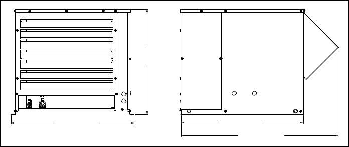
Condensing unit
|
25 .75" |
|
(65 .3 cm) |
30" (76 .2 cm) |
29 .9" (76 cm) |
|
38 .5" (97 .5 cm) |
8 |
HC_1810R/N, HC_2110R/N, HM_1810R/N, HM_2110R/N |

Operation
Cleaning/sanitizing and preventive maintenance (all models)
Note: Do not use bleach to sanitize or clean the icemaker..
Preventive maintenance
Periodic cleaning of Follett’s icemaker system is required to ensure peak performance and delivery of clean, sanitary ice. The recommended cleaning procedures that follow should be performed at least as frequently as recommended, and more often if environmental conditions dictate.
Cleaning of the condenser can usually be performed by facility personnel. Cleaning of the icemaker system, in most cases, should be performed by your facility’s maintenance staff or a Follett authorized service agent.
Regardless of who performs the cleaning, it is the operator’s responsibility to see that this cleaning is performed according to the schedule below. Service problems resulting from lack of preventive maintenance will not be covered under the Follett warranty.
Weekly exterior care
The exterior may be cleaned with a stainless cleaner such as 3M Stainless Steel Cleaner & Polish or equivalent.
Monthly condenser cleaning (air-cooled icemaker only)
1.Use a vacuum cleaner or stiff brush to carefully clean condenser coils of air-cooled icemakers to ensure optimal performance.
2.When reinstalling counter panels in front of remote icemakers, be sure that ventilation louvers line up with
condenser air duct.
Semi-annual evaporator cleaning (every 6 months)
WARNING
• Wear rubber gloves and safety goggles (and/or face shield) when handling ice machine cleaner or sanitizer.
CAUTION
•Use only Follett approved SafeCLEAN Plus™ cleaning solution..
•DO NOT USE BLEACH.
•It is a violation of Federal law to use these solutions in a manner inconsistent with their labeling.
•Read and understand all labels printed on packaging before use.
Note: Complete procedure for cleaning an sanitizing MUST be followed. Ice must be collected for 10 minutes before putting ice machine back into service.
1.Press the CLEAN button. The machine will drain. The auger will run for a short time and then stop. Wait for the LOW WATER light to come on.
Fig. 1
LO WATER |
HC_1810R/N, HC_2110R/N, HM_1810R/N, HM_2110R/N |
9 |

2.Follow the directions on the SafeCLEAN Plus packaging to mix 1 gal. (3.8 L) of Follett SafeCLEAN Plus solution. Use 100 F (38 C) water.
3.Using a 1 quart (1L) container, slowly fill cleaning cup until CLEANER FULL light comes on. Do not overfill.
4.Place one Sani-Sponge™ in remaining sanitizing and cleaning solution and retain for Step 9.
Note: Do not use bleach to sanitize or clean the icemaker.
Fig. 2
CLEANER FULL
Fig. 3
5.Replace cover on cleaner cup. Machine will clean, then flush 3 times in approximately 15 minutes. Wait until machine restarts.
15 |
Fig. 4
6.To clean/sanitize ice transport tube – Press power switch OFF
10
HC_1810R/N, HC_2110R/N, HM_1810R/N, HM_2110R/N |
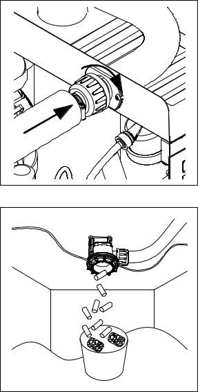
7. Disconnect coupling as shown.
8.Using disposable food service grade gloves, insert dry Sani-Sponge.
9.Insert Sani-Sponge soaked in SafeClean Plus (from Step 4).
10.Push both Sani-Sponges down ice transport tube with supplied pusher tube.
11. Remove and discard 16 inch (407 mm) pusher tube.
Fig. 5
Fig. 6
1 |
(407 |
16" |
|
||
|
2 |
mm) |
|
3 |
|
Fig. 7
HC_1810R/N, HC_2110R/N, HM_1810R/N, HM_2110R/N |
11 |
12.Reconnect coupling. Press power switch ON. Ice pushes Sani-Sponges through ice transport tube.
13.Place a sanitary (2 gal. or larger) container in bin or dispenser to collect Sani-Sponges and ice for 10 minutes.
14.Collect 5.5 lbs (3 kg) of ice from unit. Discard ice and Sani-Sponges.
Fig. 8
Fig. 9
12 |
HC_1810R/N, HC_2110R/N, HM_1810R/N, HM_2110R/N |

Service
Ice machine operation (all models)
Follett’s ice machine consists of five distinct functional systems covered in detail as follows: §§ Water system
§§ Electrical control system §§ Mechanical assembly
§§ Refrigeration system
§§ Bin full
The Horizon ice machine overview
The Follett Horizon ice machine uses a horizontal, cylindrical evaporator to freeze water on its inner surface. The refrigeration cycle is continuous; there is no batch cycle. The evaporator is flooded with water and the level is controlled by sensors in a reservoir. A rotating auger (14 RPM) continuously scrapes ice from the inner wall of the evaporator. The auger moves harvested ice through the evaporator into an ice extrusion canal. The ice is forced through a restrictive nozzle that squeezes out the water and creates the Chewblet. The continuous extrusion process pushes the Chewblets through a transport tube into a dispenser or bin.
A solid state PC board controls and monitors the functionality of the ice machine. In addition to sequencing electrical components, the board monitors various operational parameters. A full complement of indicator lights allows visual status of the machine's operation. Additionally, the PC board controls the self-flushing feature of the ice machine. The evaporator water is periodically drained and replenished to remove minerals and sediment.
A unique “bin full” detection system is incorporated in the Horizon ice machine. A switch located at the ice discharge port of the machine detects the position of the transport tube. When the bin fills up with ice, the transport tube moves out of the normal running position, and the switch turns the ice maker off. A domed housing at the end of the transport tube contains the ice extrusion loads during shut down.
Harvest system diagram
Ice Transport Tube |
|
|
Water Inlet |
Compression |
|
Nozzle |
|
|
Auger |
HC_1810R/N, HC_2110R/N, HM_1810R/N, HM_2110R/N |
13 |

Water system
The water level in the evaporator is controlled by a feed solenoid and level detecting sensors. Referencing the diagram below, water sensing probes extend down into the reservoir at the end of the evaporator assembly. The system works via electrical conductivity as follows:
The probe labeled B is the common. When water is between any of the other probes and the common, the PC board will sense the activation. During normal operation, the water level rises and falls between the Normal High and Normal Low probes. As water is consumed to make ice, the level will fall until the Normal Low probe is exposed, triggering the water feed solenoid on. Water will fill until the Normal High sensor is activated.
Note: The potable water total dissolved solids (TDS) content must be greater than 10 ppm for the water control system to function properly. If using reverse osmosis water filtration system, ensure TDS level is greater than 10 ppm.
Water system diagram
Water level diagram
Common |
Normal Hi |
Normal Lo |
Normal |
|
|
Operating |
|
|
Range |
|
|
14 |
|
HC_1810R/N, HC_2110R/N, HM_1810R/N, HM_2110R/N |

“Bin full” detection system
The Follett Horizon ice machine incorporates a unique “bin full” detection system that consists of the shuttle and actuator. The shuttle incorporates a flag and switch. Referencing the figure below, the normal running position of the flag is down, and the switch is closed. When the bin fills to the top and ice can no longer move through the tube, the machine will force the shuttle flag up, opening the switch and shutting the machine off. The shuttle actuator, located above the ice bin allows the ice to curl up within it when the bin is full. In this way, there are no loads generated that would tend to lift off the lid of the bin.
Shuttle flag and sensor
Running |
Off |
Shuttle actuator
Running |
Off |
HC_1810R/N, HC_2110R/N, HM_1810R/N, HM_2110R/N |
15 |

Electrical system
ATTENTION!
To prevent circuit breaker/Hi-amp overload, wait 5 minutes before restarting this unit. This allows the compressor to equalize and the evaporator to thaw.
Normal control board operation
The PC board indicator lights provide all the information necessary to determine the machine's status. Green indicator lights generally represent “go” or normal operation; Yellow indicators represent normal off conditions; Red indicators generally represent alarm conditions, some of which will lock the machine off.
A flashing green light labeled POWER indicates power to the machine. All other normal operation status indicators are covered as follows:
Ice machine disposition |
|
|
Operating conditions |
|
Legend: |
ON |
OFF |
ON or OFF |
FLASHING |
1. Ice machine is making ice.. |
|
1. Normal running. |
||
..
2.Ice machine is not making ice.. 2. Normal time delay. When the bin fills with ice, the LOW BIN
light goes out momentarily and the refrigeration and auger drive systems immediately shut down. (Note: The fan motor will continue to run for 10 minutes to cool condenser) The TIME DELAY light comes on, initiating the time delay period. When the time delay expires, the machine will restart provided that the LOW BIN light is on.
DIP Switch Settings
SET TO OFF
SET TO OFF
SET TO OFF
SET TO OFF
SET TO OFF
|
|
|
|
|
|
|
|
|
|
|
|
16 |
|
|
|
|
|
|
|
|
|
HC_1810R/N, HC_2110R/N, HM_1810R/N, HM_2110R/N |
|
|
|
|
|
|
|
|
|
|
|||
|
|
|
|
|
|
|
|
|
|||
|
|
|
|
|
|
|
|
|
|||
|
|
|
|
|
|
|
|
|
|||
 Loading...