


Countertop and Freestanding Ice and Water Dispenser with Chewblet® Ice Icemaker 7CI100A, 7FS100A
Installation, Operation and Service Manual
Serial numbers before D17617
7CI100A |
7FS100A |
Following installation, please forward this manual to the appropriate operations person.
801 Church Lane • Easton, PA 18040, USA |
Order parts online: |
Toll free (877) 612-5086 • +1 (610) 252-7301 |
www.follettice.com |
www.follettice.com |
00951640R01 |

Contents |
|
Welcome. . . . . . . . . . . . . . . . . . . . . . . . . . . . . . . . . . . . . . . . . . . . . . . . . . . . . . . . . . . . . . . . . . . . . . . . . . . . . . . . . . . . . . |
3 |
Before You Begin. . . . . . . . . . . . . . . . . . . . . . . . . . . . . . . . . . . . . . . . . . . . . . . . . . . . . . . . . . . . . . . . . . . . . . . . . . . . . . . |
3 |
Important Safety Information. . . . . . . . . . . . . . . . . . . . . . . . . . . . . . . . . . . . . . . . . . . . . . . . . . . . . . . . . . . . . . . . . . . . . |
3 |
Specifications. . . . . . . . . . . . . . . . . . . . . . . . . . . . . . . . . . . . . . . . . . . . . . . . . . . . . . . . . . . . . . . . . . . . . . . . . . . . . . . . . . |
4 |
Dimensions. . . . . . . . . . . . . . . . . . . . . . . . . . . . . . . . . . . . . . . . . . . . . . . . . . . . . . . . . . . . . . . . . . . . . . . . . . . . . . . . . |
4 |
Ambient Information.. . . . . . . . . . . . . . . . . . . . . . . . . . . . . . . . . . . . . . . . . . . . . . . . . . . . . . . . . . . . . . . . . . . . . . . . . . |
4 |
Plumbing. . . . . . . . . . . . . . . . . . . . . . . . . . . . . . . . . . . . . . . . . . . . . . . . . . . . . . . . . . . . . . . . . . . . . . . . . . . . . . . . . . . |
4 |
Water . . . . . . . . . . . . . . . . . . . . . . . . . . . . . . . . . . . . . . . . . . . . . . . . . . . . . . . . . . . . . . . . . . . . . . . . . . . . . . . . . . . . . . |
4 |
Clearances ................................................................................. |
4 |
Electrical.. . . . . . . . . . . . . . . . . . . . . . . . . . . . . . . . . . . . . . . . . . . . . . . . . . . . . . . . . . . . . . . . . . . . . . . . . . . . . . . . . . . |
4 |
Refrigeration.. . . . . . . . . . . . . . . . . . . . . . . . . . . . . . . . . . . . . . . . . . . . . . . . . . . . . . . . . . . . . . . . . . . . . . . . . . . . . . . . |
4 |
Heat Rejection . . . . . . . . . . . . . . . . . . . . . . . . . . . . . . . . . . . . . . . . . . . . . . . . . . . . . . . . . . . . . . . . . . . . . . . . . . . . . . . |
4 |
Detailed Drawing . . . . . . . . . . . . . . . . . . . . . . . . . . . . . . . . . . . . . . . . . . . . . . . . . . . . . . . . . . . . . . . . . . . . . . . . . . . . . |
5 |
Installation.. . . . . . . . . . . . . . . . . . . . . . . . . . . . . . . . . . . . . . . . . . . . . . . . . . . . . . . . . . . . . . . . . . . . . . . . . . . . . . . . . . . . |
6 |
Countertop Installation. . . . . . . . . . . . . . . . . . . . . . . . . . . . . . . . . . . . . . . . . . . . . . . . . . . . . . . . . . . . . . . . . . . . . . . . . |
6 |
Freestanding Installation. . . . . . . . . . . . . . . . . . . . . . . . . . . . . . . . . . . . . . . . . . . . . . . . . . . . . . . . . . . . . . . . . . . . . . . |
8 |
Maintenance/Cleaning Mode. . . . . . . . . . . . . . . . . . . . . . . . . . . . . . . . . . . . . . . . . . . . . . . . . . . . . . . . . . . . . . . . . . . . . |
11 |
Accessing Internal Components. . . . . . . . . . . . . . . . . . . . . . . . . . . . . . . . . . . . . . . . . . . . . . . . . . . . . . . . . . . . . . . . . |
11 |
Filter Display Indicator Activation.. . . . . . . . . . . . . . . . . . . . . . . . . . . . . . . . . . . . . . . . . . . . . . . . . . . . . . . . . . . . . . . . |
12 |
Cleaning and Sanitizing.. . . . . . . . . . . . . . . . . . . . . . . . . . . . . . . . . . . . . . . . . . . . . . . . . . . . . . . . . . . . . . . . . . . . . . . . |
13 |
Service. . . . . . . . . . . . . . . . . . . . . . . . . . . . . . . . . . . . . . . . . . . . . . . . . . . . . . . . . . . . . . . . . . . . . . . . . . . . . . . . . . . . . . . |
14 |
LED Indicator Description. . . . . . . . . . . . . . . . . . . . . . . . . . . . . . . . . . . . . . . . . . . . . . . . . . . . . . . . . . . . . . . . . . . . . |
14 |
Water Feed Schematic.. . . . . . . . . . . . . . . . . . . . . . . . . . . . . . . . . . . . . . . . . . . . . . . . . . . . . . . . . . . . . . . . . . . . . . . |
15 |
Bin Melt Water/Evaporator Feed/Clean Out System Schematic . . . . . . . . . . . . . . . . . . . . . . . . . . . . . . . . . . . . . . . . |
16 |
Refrigeration Schematic.. . . . . . . . . . . . . . . . . . . . . . . . . . . . . . . . . . . . . . . . . . . . . . . . . . . . . . . . . . . . . . . . . . . . . . |
17 |
Condenser Fan Motor Removal. . . . . . . . . . . . . . . . . . . . . . . . . . . . . . . . . . . . . . . . . . . . . . . . . . . . . . . . . . . . . . . . . |
18 |
User Interface Display Identification. . . . . . . . . . . . . . . . . . . . . . . . . . . . . . . . . . . . . . . . . . . . . . . . . . . . . . . . . . . . . |
19 |
Electrical Wiring Diagram.. . . . . . . . . . . . . . . . . . . . . . . . . . . . . . . . . . . . . . . . . . . . . . . . . . . . . . . . . . . . . . . . . . . . . |
21 |
Parts. . . . . . . . . . . . . . . . . . . . . . . . . . . . . . . . . . . . . . . . . . . . . . . . . . . . . . . . . . . . . . . . . . . . . . . . . . . . . . . . . . . . . . . . . |
22 |
Exterior.. . . . . . . . . . . . . . . . . . . . . . . . . . . . . . . . . . . . . . . . . . . . . . . . . . . . . . . . . . . . . . . . . . . . . . . . . . . . . . . . . . . |
22 |
Interior. . . . . . . . . . . . . . . . . . . . . . . . . . . . . . . . . . . . . . . . . . . . . . . . . . . . . . . . . . . . . . . . . . . . . . . . . . . . . . . . . . . . |
24 |
Bin Assembly . . . . . . . . . . . . . . . . . . . . . . . . . . . . . . . . . . . . . . . . . . . . . . . . . . . . . . . . . . . . . . . . . . . . . . . . . . . . . . . |
26 |
Evaporator Assembly. . . . . . . . . . . . . . . . . . . . . . . . . . . . . . . . . . . . . . . . . . . . . . . . . . . . . . . . . . . . . . . . . . . . . . . . . |
28 |
Base Stand. . . . . . . . . . . . . . . . . . . . . . . . . . . . . . . . . . . . . . . . . . . . . . . . . . . . . . . . . . . . . . . . . . . . . . . . . . . . . . . . |
30 |
2 Dispenser and Icemaker 7CI100A/7FS100A

Welcome––––––––––––––––––––––––––––––––––––––––––––––––––––––––––
Follett equipment enjoys a well-deserved reputation for excellent performance, long-term reliability, and outstanding after-the-sale support.. To ensure that this product delivers that same degree of service, we ask that you take a moment to review this manual before beginning the installation.. Should you have any questions or require technical help at any point, please call our technical service group at (877) 612-5086 or +1 (610) 252-7301..
Before You Begin––––––––––––––––––––––––––––––––––––––––––––––––––––
After uncrating and removing all packing material, inspect the equipment for concealed shipping damage.. If damage is found, immediately notify the shipper and contact Follett Corporation so that we can help in the filing of a claim, if necessary..
Check your paperwork to verify that you received the correct dispenser.. Follett configuration numbers are designed to provide information about the type of dispenser you are receiving.. The following is an explanation of the different model numbers..
|
|
|
7 |
|
|
CI |
|
100 |
|
|
A |
|
|
|
|
||||
|
|
|
|
|
|
|
|
|
|
|
|
|
|
|
|
|
|
|
|
|
|
|
|
|
|
|
|
|
|
|
|
|
|
|
|
||||
|
|
|
|
|
|
|
|
|
|
|
|
|
|
|
|||||
|
|
|
|
|
|
|
|
|
|
|
|
|
|
|
|
|
|
|
|
|
Model |
|
Configuration |
|
|
|
|
|
Series |
|
Condenser |
||||||||
|
|
|
|
|
|
|
|
||||||||||||
7 Series |
|
|
CI |
Countertop |
100 lbs per day (icemaker |
A |
Air-cooled |
||||||||||||
|
|
|
FS |
Freestanding |
|
|
capacity) |
|
|
|
|||||||||
|
|
|
|
|
|
|
|
|
|
|
|
|
|
|
|
|
|
|
|
Important Safety Information––––––––––––––––––––––––––––––––––––––––––
Please read and adhere to the following safety information while installing, using, or servicing your Follett 7 Series Ice Dispenser..
1.Always disconnect power before servicing the dispenser..
2.Ice is slippery.. Maintain counters and floors around dispenser in a clean and ice-free condition..
3.Ice is food.. Follow the recommended cleaning and sanitizing instructions to maintain cleanliness of delivered ice..
Dispenser and Icemaker 7CI100A/7FS100A |
3 |

Specifications– –––––––––––––––––––––––––––––––––––––––––––––––––––––
Dimensions
|
7CI100A |
7FS100A |
|
|
|
Width |
14..55" (370 mm) |
14..55" (370 mm) |
|
|
|
Depth |
22..05" (560 mm) |
22..05" (560 mm) |
|
|
|
Height |
17..53" (450 mm) |
41..93" (1065 mm) |
|
|
|
Unit Shipping Weight |
90 lb (41 kg) |
120 lb (54..4 kg) |
|
|
|
Ambient Information
 CAUTION!
The 7CI100A and 7FS100A are for indoor use only.
|
Maximum |
|
|
Minimum |
|
|
|
|
|
Air Temperature* |
100 F (38 C) |
|
50 |
F (10 C) |
|
|
|
|
|
Water Temperature |
90 F (32..2 C) |
|
40 |
F (4..5 C) |
|
|
|
|
|
Water Pressure |
70 psi |
|
10 psi |
|
|
|
|
|
|
Relative Humidity |
|
55% at 78 F |
||
|
|
|
|
|
* Best performance is achieved between 80 F (27 C) and 50 F (10 C)..
Plumbing
§§ Water Inlet: 1/4" MPT
§§ Optional Drain Accessory Kit (item# 00956375): 1/2" ID tubing
§§ Water Mineral Content: Greater than 5 ppm (mg/l) TDS and less than 400 ppm (mg/l) TDS §§ Water shut-off recommended within 10 feet (3 m) of dispenser
Water
§§ For use in applications with less than 400 ppm (mg/l) total dissolved solids in water (either naturally occurring or treated with reverse osmosis)
§§ Not recommended for use with softened water
Clearances
§§ 3" (77 mm) behind and on each side of dispenser for electrical and connection and ventilation
Electrical
§§ 115V, 60 Hz, 1 phase, 5A, maximum fuse 15A
§§ Connect to dedicated 15A circuit, fuse or breaker.. Note: It is preferred that circuit be protected by a GFCI
Refrigeration
§§ Refrigerant R134a – 7..2 ounces (204 grams)
Heat Rejection
§§ 1700 BTU/hr (498 W)
4 Dispenser and Icemaker 7CI100A/7FS100A

Specifications (continued)– ––––––––––––––––––––––––––––––––––––––––––––––
Detailed Drawing
Countertop models |
|
|
|
|
14.55" (370 mm) |
|
|
14.55" (370 mm) |
|
|
NEMA 5-15 |
L2 |
|
|
17.54" |
right angle |
G |
|
17.54" |
L1 |
|
|||
(446 mm) |
|
|
|
(446 mm) |
|
|
6.79" |
|
6.72" |
|
|
(172 mm) |
|
(171 mm) |
|
power cord |
|
|
|
|
22.05" (560 mm) |
2.40" |
1/4" NPT |
2.98" |
|
|
|||
|
|
(61 mm) |
water inlet |
(76 mm) |
Freestanding models |
|
|
|
|
14.55" (370 mm) |
|
|
14.55" (370 mm) |
|
17.54" |
NEMA 5-15 |
L2 |
|
17.54" |
right angle |
G |
|
||
(446 mm) |
L1 |
|
(446 mm) |
|
|
|
|
||
|
|
6.79" |
|
6.72" |
|
|
(172 mm) |
|
(171 mm) |
|
power cord |
|
|
|
|
|
2.40" |
|
2.98" |
|
|
(61 mm) |
1/4" NPT |
(76 mm) |
|
|
|
|
|
|
|
|
water inlet |
|
24.39" |
|
|
|
|
(620 mm) |
|
|
|
|
|
22.05" (560 mm) |
|
|
|
Dispenser and Icemaker 7CI100A/7FS100A |
5 |

Installation–––––––––––––––––––––––––––––––––––––––––––––––––––––––––


 CAUTION!
No service or maintenance should be performed until the technician has thoroughly read this service manual. Except for routine cleaning and sanitizing, only qualified technicians should attempt to service or maintain this equipment.
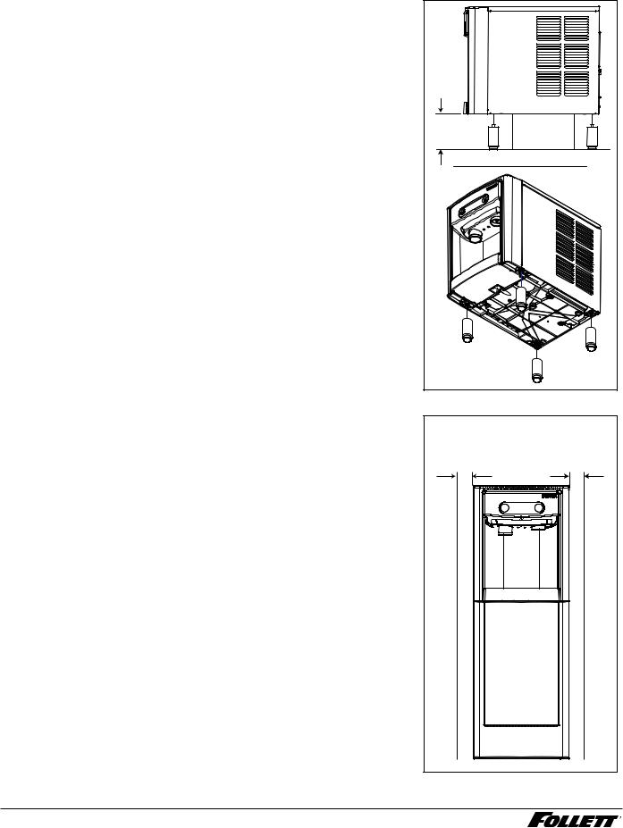
Countertop Installation |
Fig.. 1 |
|
Installation instructions for freestanding model may be found on page 8.. |
countertop models |
|
|
|
|
1. |
A clearance of at least 3" (77 mm) is required behind and on |
minimum 3" (77 mm) |
|
each side of the dispenser for electrical connection and ventilation |
|
|
clearance required |
|
|
(Fig.. 1).. |
|
|
|
|
2. |
Rough-in the electrical service and water line.. |
|
|
§§ Electrical: 115V, single phase, 15A receptacle required.. The dispenser |
|
|
has an integral 8 ft.. (2..4 m) cord and plug.. |
|
|
§§ Water: supply line (with shut-off valve) connects to the dispenser's 1/4" |
|
|
MPT inlet.. |
|
NOTICE!
If installing optional Drip Tray Drain Kit or Leg Accessory, complete those steps before proceeding.
3.Connect water line.. Recommended routing (Fig.. 2) allows easy access to water for cleaning and sanitizing procedure..
4.Connect power supply..
5.Sanitize the dispenser prior to use (see Cleaning and Sanitizing on page 13)..
Fig.. 2
3' (76 mm) |
1/4" MPT |
6 Dispenser and Icemaker 7CI100A/7FS100A

Installation (continued) –––––––––––––––––––––––––––––––––––––––––––––––––
Optional Drip Tray Drain Installation |
Fig.. 3 |
1. |
If installing optional Drip Tray Drain Kit*, cut hole in countertop for |
|
|
|
drain tube.. Units without legs must have alternate hole positioning |
|
|
|
(Fig.. 3) |
|
|
|
* The optional Drip Tray Drain Kit (item# 00956375) requires a floor drain within |
3" |
15 3/4" |
|
15 ft.. (4..5 m) of the dispenser.. For detailed installation instructions, please |
(76 mm) |
(400 mm) |
|
refer to the instructions shipped with the Drip Tray Drain Kit.. |
|
|
|
|
|
6" |
|
|
|
(152 mm) |
|
|
|
6 5/16" |
|
|
|
(160 mm) |
2. Remove drip tray and drill 11/32" hole through drain nipple (Fig.. 4).. |
Fig.. 4 |
3.Connect supplied drain tubing to drain tray nipple with supplied hose
clamp.. Run drain tubing to floor drain.. 4. Return tray to original position..
Dispenser and Icemaker 7CI100A/7FS100A |
7 |
Installation (continued) –––––––––––––––––––––––––––––––––––––––––––––––––
Optional Leg Accessory Installation
1.If installing optional 4" Leg Accessory (item# 00956300), place a 5" (127 mm) spacer underneath the dispenser to ease installation..
2.Remove four plastic, thread-protecting plugs from bottom of dispenser..
3.Screw each leg into chassis (Fig.. 3)..
Fig.. 5
5" (127 mm) |
spacer |
|
min. |
||
|
Freestanding Installation |
Fig.. 6 |
||
Installation instructions for countertop model may be found on page 6. |
freestanding models |
||
1. |
A clearance of at least 3" (77 mm) is required behind and on |
||
minimum 3" (77 mm) |
|||
|
each side of the dispenser for electrical connection and ventilation |
||
|
clearance required |
||
|
(Fig.. 1).. |
||
|
|
||
2. |
Rough-in the electrical service and water line.. |
|
|
|
§§ Electrical: 115V, single phase, 15A receptacle required.. The dispenser |
|
|
|
has an integral 8 ft.. (2..4 m) cord and plug.. |
|
|
|
§§ Water: supply line (with shut-off valve) connects to the dispenser's 1/4" |
|
|
|
MPT inlet.. |
|
|
NOTICE!
If using Leg Accessory with base stand, complete those steps before proceeding.
8 Dispenser and Icemaker 7CI100A/7FS100A

Installation (continued) –––––––––––––––––––––––––––––––––––––––––––––––––
3.Remove four plastic, thread-protecting plugs from bottom of dispenser..
4.Attach dispenser to base stand with supplied hardware (Fig.. 7)..
NOTICE!
If installing optional Drip Tray Drain Kit, complete those steps before proceeding.
Fig.. 7
X4 |
5.Connect water line.. Recommended routing (Fig.. 8) allows easy access to water for cleaning and sanitizing procedure..
6.Connect power supply..
7.Sanitize the dispenser prior to use (see Cleaning and Sanitizing on page 13)..
Fig.. 8
3' (76 mm) |
1/4" MPT |
Dispenser and Icemaker 7CI100A/7FS100A |
9 |
Installation (continued) –––––––––––––––––––––––––––––––––––––––––––––––––
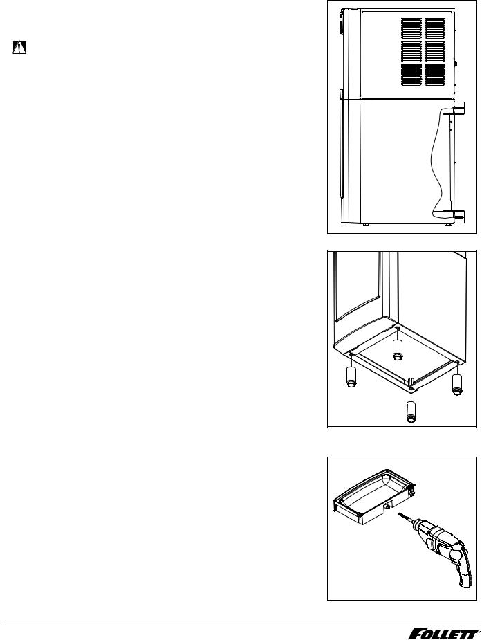
8. Secure unit to wall or cove molding with supplied bracket (Fig.. 9) to |
Fig.. 9 |
prevent tipping.. |
|
Note: Fasteners must be supplied by installer.. |
|
WARNING!
Freestanding unit must be secured to wall to prevent tipping. Failure to do could result in personal injury or damage to the unit.
Optional Leg Accessory Installation
1.If installing optional 6" Leg Accessory (item# 00956318), tilt or lay base stand on side and screw each leg into stand (Fig.. 10)..
Optional Drip Tray Drain Installation
Fig.. 10 |
Fig.. 11
1.If installing optional Drip Tray Drain Kit*, remove drip tray and drill 11/32" hole through drain nipple (Fig.. 11)..
2.Connect supplied drain tubing to drain tray nipple with supplied hose clamp.. Run drain tubing to floor drain..
3.Return tray to original position..
*The optional Drip Tray Drain Kit (item# 00956375) requires a floor drain within 15 ft.. (4..5 m) of the dispenser.. For detailed installation instructions, please refer to the instructions shipped with the Drip Tray Drain Kit..
10 Dispenser and Icemaker 7CI100A/7FS100A
 Loading...