


Symphony Plus™ 110 Series
Ice and Water Dispensers
Installation, Operation and Service Manual
110CT425A/W |
110CR425A/W |
110FB425A/W |
Following installation, please forward this manual to the appropriate operations person.
801 Church Lane • Easton, PA 18040, USA
Toll free (877) 612-5086 • +1 (610) 252-7301 www.follettice.com
Order parts online: www.follettice.com 01033792R03
Contents
Welcome to Follett. . . . . . . . . . . . . . . . . . . . . . . . . . . . . . . . . . . . . . . . . . . . . . . . . . . . . . . . . . . . . . . . . . . . . . . . . . |
. 3 |
Before you begin. . . . . . . . . . . . . . . . . . . . . . . . . . . . . . . . . . . . . . . . . . . . . . . . . . . . . . . . . . . . . . . . . . . . . . . . . . |
3 |
Specifications. . . . . . . . . . . . . . . . . . . . . . . . . . . . . . . . . . . . . . . . 4 |
|
Electrical.. . . . . . . . . . . . . . . . . . . . . . . . . . . . . . . . . . . . . . . . . . . . . . . . . . . . . . . . . . . . . . . . . . . . . . . . . . . . . . . . |
4 |
Ambient. . . . . . . . . . . . . . . . . . . . . . . . . . . . . . . . . . . . . . . . . . . . . . . . . . . . . . . . . . . . . . . . . . . . . . . . . . . . . . . . . |
4 |
Plumbing. . . . . . . . . . . . . . . . . . . . . . . . . . . . . . . . . . . . . . . . . . . . . . . . . . . . . . . . . . . . . . . . . . . . . . . . . . . . . . . . |
4 |
Ventilation clearances. . . . . . . . . . . . . . . . . . . . . . . . . . . . . . . . . . . . . . . . . . . . . . . . . . . . . . . . . . . . . . . . . . . . . . |
5 |
Approximate shipping weight. . . . . . . . . . . . . . . . . . . . . . . . . . . . . . . . . . . . . . . . . . . . . . . . . . . . . . . . . . . . . . . . . |
5 |
Installation. . . . . . . . . . . . . . . . . . . . . . . . . . . . . . . . . . . . . . . . . |
5 |
Before you begin. . . . . . . . . . . . . . . . . . . . . . . . . . . . . . . . . . . . . . . . . . . . . . . . . . . . . . . . . . . . . . . . . . . . . . . . . . |
5 |
Installing freestanding dispensers . . . . . . . . . . . . . . . . . . . . . . . . . . . . . . . . . . . . . . . . . . . . . . . . . . . . . . . . . . . . . |
5 |
Installing countertop dispensers. . . . . . . . . . . . . . . . . . . . . . . . . . . . . . . . . . . . . . . . . . . . . . . . . . . . . . . . . . . . . . |
7 |
Installing RIDE ice machines. . . . . . . . . . . . . . . . . . . . . . . . . . . . . . . . . . . . . . . . . . . . . . . . . . . . . . . . . . . . . . . . . |
9 |
Installing top mount ice machines . . . . . . . . . . . . . . . . . . . . . . . . . . . . . . . . . . . . . . . . . . . . . . . . . . . . . . . . . . . . |
10 |
User information. . . . . . . . . . . . . . . . . . . . . . . . . . . . . . . . . . . . . . |
12 |
How the dispenser works.. . . . . . . . . . . . . . . . . . . . . . . . . . . . . . . . . . . . . . . . . . . . . . . . . . . . . . . . . . . . . . . . . . |
12 |
How SensorSAFE infrared dispensing works . . . . . . . . . . . . . . . . . . . . . . . . . . . . . . . . . . . . . . . . . . . . . . . . . . . |
12 |
Quiet Night™/Sleep cycle (does not apply to CR units) . . . . . . . . . . . . . . . . . . . . . . . . . . . . . . . . . . . . . . . . . . . |
12 |
Cleaning/descaling and sanitizing . . . . . . . . . . . . . . . . . . . . . . . . . . . . . . . 12
Weekly . . . . . . . . . . . . . . . . . . . . . . . . . . . . . . . . . . . . . . . . . . . . . . . . . . . . . . . . . . . . . . . . . . . . . . . . . . . . . . . . . |
13 |
Monthly.. . . . . . . . . . . . . . . . . . . . . . . . . . . . . . . . . . . . . . . . . . . . . . . . . . . . . . . . . . . . . . . . . . . . . . . . . . . . . . . . |
13 |
Semi-Annually (more often if conditions dictate) . . . . . . . . . . . . . . . . . . . . . . . . . . . . . . . . . . . . . . . . . . . . . . . . |
. 14 |
Ice Machine and Dispenser. . . . . . . . . . . . . . . . . . . . . . . . . . . . . . . . . . . . . . . . . . . . . . . . . . . . . . . . . . . . . . . . . |
14 |
Dispenser only. . . . . . . . . . . . . . . . . . . . . . . . . . . . . . . . . . . . . . . . . . . . . . . . . . . . . . . . . . . . . . . . . . . . . . . . . . . |
15 |
Service. . . . . . . . . . . . . . . . . . . . . . . . . . . . . . . . . . . . . . . . . . |
17 |
Lever models . . . . . . . . . . . . . . . . . . . . . . . . . . . . . . . . . . . . . . . . . . . . . . . . . . . . . . . . . . . . . . . . . . . . . . . . . . . . |
17 |
SensorSAFE models . . . . . . . . . . . . . . . . . . . . . . . . . . . . . . . . . . . . . . . . . . . . . . . . . . . . . . . . . . . . . . . . . . . . . . |
17 |
Wiring diagram - Lever.. . . . . . . . . . . . . . . . . . . . . . . . . . . . . . . . . . . . . . . . . . . . . . . . . . . . . . . . . . . . . . . . . . . . |
18 |
Wiring diagram - SensorSAFE.. . . . . . . . . . . . . . . . . . . . . . . . . . . . . . . . . . . . . . . . . . . . . . . . . . . . . . . . . . . . . . |
19 |
Dispenser troubleshooting . . . . . . . . . . . . . . . . . . . . . . . . . . . . . . . . . |
. 20 |
Lever model troubleshooting guide . . . . . . . . . . . . . . . . . . . . . . . . . . . . . . . . . . . . . . . . . . . . . . . . . . . . . . . . . . . |
20 |
SensorSAFE model troubleshooting guide . . . . . . . . . . . . . . . . . . . . . . . . . . . . . . . . . . . . . . . . . . . . . . . . . . . . . |
21 |
Disassembly and replacement instructions. . . . . . . . . . . . . . . . . . . . . . . . . . |
22 |
Ice transport tube replacement – Top mount units. . . . . . . . . . . . . . . . . . . . . . . . . . . . . . . . . . . . . . . . . . . . . . . |
23 |
Ice transport tube replacement – Freestanding and RIDE models. . . . . . . . . . . . . . . . . . . . . . . . . . . . . . . . . . . |
23 |
Thermostat replacement. . . . . . . . . . . . . . . . . . . . . . . . . . . . . . . . . . . . . . . . . . . . . . . . . . . . . . . . . . . . . . . . . . . |
24 |
Replacement parts. . . . . . . . . . . . . . . . . . . . . . . . . . . . . . . . . . . . . |
25 |
Dispenser exterior. . . . . . . . . . . . . . . . . . . . . . . . . . . . . . . . . . . . . . . . . . . . . . . . . . . . . . . . . . . . . . . . . . . . . . . . |
25 |
Wheelmotor and drive system . . . . . . . . . . . . . . . . . . . . . . . . . . . . . . . . . . . . . . . . . . . . . . . . . . . . . . . . . . . . . . . |
26 |
Dispense chute and splash panel (models with lever dispensing) . . . . . . . . . . . . . . . . . . . . . . . . . . . . . . . . . . . |
27 |
Dispense chute and splash panel (models with SensorSAFE infrared dispensing). . . . . . . . . . . . . . . . . . . . . . |
28 |
Electrical components . . . . . . . . . . . . . . . . . . . . . . . . . . . . . . . . . . . . . . . . . . . . . . . . . . . . . . . . . . . . . . . . . . . . . |
29 |
Hopper components.. . . . . . . . . . . . . . . . . . . . . . . . . . . . . . . . . . . . . . . . . . . . . . . . . . . . . . . . . . . . . . . . . . . . . . |
30 |
Ice transport tubing. . . . . . . . . . . . . . . . . . . . . . . . . . . . . . . . . . . . . . . . . . . . . . . . . . . . . . . . . . . . . . . . . . . . . . . |
31 |
Chilled water components . . . . . . . . . . . . . . . . . . . . . . . . . . . . . . . . . . . . . . . . . . . . . . . . . . . . . . . . . . . . . . . . . . |
31 |
Dispenser plumbing connections.. . . . . . . . . . . . . . . . . . . . . . . . . . . . . . . . . . . . . . . . . . . . . . . . . . . . . . . . . . . . |
32 |
Solenoid dispense assembly. . . . . . . . . . . . . . . . . . . . . . . . . . . . . . . . . . . . . . . . . . . . . . . . . . . . . . . . . . . . . . . . |
33 |
Water treatment accessories for Symphony Plus ice and water dispensers . . . . . . . . . . . . . |
34 |
2 |
100CR/CT/FB Ice and Water Dispensers |
Welcome to Follett
Follett equipment enjoys a well-deserved reputation for excellent performance, long-term reliability and outstanding after-the-sale support.. To ensure that this equipment delivers that same degree of service, we ask that you take
a moment to review the installation portion of this manual before beginning to install the unit.. Our installation instructions are designed to help you achieve a trouble-free installation.. Should you have any questions or require technical help at any point, please call our technical service group at (877) 612-5086 or
(610) 252-7301..
Note: To expedite assistance, all correspondence or communication MUST include the model number, serial number and complete and detailed explanation of the problem..
Before you begin
After uncrating and removing all packing material, inspect the equipment for concealed shipping damage.. If damage is found, notify the shipper immediately and contact Follett Corporation so that we can help in the filing of a claim, if necessary..
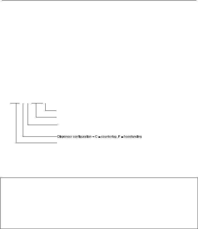
Check your paperwork to determine which model you have.. Follett model numbers are designed to provide information about the type and capacity of Follett ice dispensing equipment.. Following is an explanation of the different model numbers..
110CT425A-L
 L = Lever dispensing, S = SensorSAFE infrared dispensing Condenser type – A = air-cooled, W = water-cooled
Ice machine capacity and refrigerant – 425 = 425 lbs (193 kg)/day, R404a refrigerant
Ice machine location – R = RIDE ice machine, T = integral ice machine in top of cabinet,
B = ice machine in base of freestanding units
Approximate storage capacity in lbs


 CAUTION!
§§ Do not tilt any unit further than 30° off vertical during uncrating or installation..
§§ Dispenser bin area contains mechanical, moving parts.. Keep hands and arms clear of this area at all times.. If access to this area is required, power to unit must be disconnected first..
§§ Follett recommends a Follett water filter system be installed in the ice machine inlet water line (standard capacity #00130229, high capacity #00978957, carbonless high capacity #01050442)..
§§ Prior to operation clean and sanitize the dispenser in accordance with instructions found in this manual.. §§ Ice is slippery.. Be sure counters and floors around dispenser are clean, dry and free of ice..
§§ Do not block right side air intake or top air exhaust..
100CR/CT/FB Ice and Water Dispensers |
3 |

Specifications
Electrical
§§ Models with RIDE ice machines (110CR425A/W).. Ice machine and dispenser require their own separate, dedicated circuit..
|
Dispenser with |
Max. |
Dispenser without |
Max. |
|
ice machine |
circuit |
ice machine |
circuit |
|
|
|
|
|
Basic electrical: 115 V/60 Hz/1 phase |
11..0A |
20A |
4..0A |
20A |
|
|
|
|
|
§§ Freestanding models (110FB425A/W, 110CT425A/W) require a dedicated circuit..
|
Total system |
Max. circuit |
Basic electrical: 115 V/60 Hz/1 phase |
11..0A |
20A |
|
|
|
§§ Dispensers and RIDE ice machines are supplied with 7-foot power cord with NEMA 5-15 hospital-grade plug.. Connect to a dedicated 15A circuit..


 CAUTION!
All field wiring must be installed in accordance with NEC and local electrical codes.. Field wiring diagram is intended only to aid electrician or technician in understanding how equipment works..
Model |
Electrical connection |
Circuits required |
|
|
|
110FB425A/W |
cord & plug provided |
115/60/1, 15A max.. fuse size |
|
|
|
110CT425A/W |
cord & plug provided |
115/60/1, 15A max.. fuse size |
|
|
|
110CR425A/W |
cord & plug provided |
115/60/1 |
|
|
Dispenser: 15A max.. fuse size, |
|
|
Ice machine: 15A max.. fuse size |
Ambient
Air temp* |
100 F/38 C Max.. |
50 |
F/10 C Min.. (Best performance below 80 F/27 C) |
|
|
|
|
|
|
Water temp† |
90 |
F/32 C Max.. |
45 |
F/7..2 C Min.. (Best performance below 70 F/21 C) |
Water pressure |
70 |
P..S..I../5Bar Max.. |
10 P..S..I../0..7 Bar Min.. |
|
|
|
|
||
* Ambient air temperature is measured at the air-cooled condenser coil inlet.. |
||||
† Ambient water temperature is measured in the ice machine reservoir.. |
|
|||
Plumbing
|
110CR with RIDE ice |
110CT with integral |
110FB with ice |
|
machine |
ice machine |
machine in base |
Dispenser drain |
3/4" MPT |
3/4" MPT |
3/4" MPT |
|
|
|
|
Ice machine drain |
3/4" MPT |
3/4 MPT |
3/4" MPT |
|
|
|
|
Dispenser water inlet |
3/8" FPT |
3/8" FPT |
3/8" FPT |
|
|
|
|
Ice machine water inlet |
— |
3/8" FPT |
— |
RIDE IM water inlet |
3/8" FPT |
— |
— |
|
|
|
|
Cond.. inlet – w/c only |
3/8" FPT |
3/8" FPT |
3/8" FPT |
|
|
|
|
Cond.. drain – w/c only |
3/8" FPT |
3/8" FPT |
3/8" FPT |
|
|
|
|
Note: Water shut-off recommended within 10 ft (3 m) of dispenser.. Drain to be hard-piped and insulated.. Maintain at least 1/4" per foot (20 mm per 1 m) run of slope..
4 |
100CR/CT/FB Ice and Water Dispensers |

Ventilation clearances
§§ No clearance required for countertop models with RIDE ice machine (110CR425A/W)..
Note: 12" (30.5 cm) at top advised for service.
§§ 6" (15..2 cm) required at top (110CT425A/W)..
Note: 6" (15.2 cm) at each side advised for service.
§§ 4" (10..2 cm) required at rear (110FB425A/W)..
Note: 12" (30.5 cm) at top advised for service.
Approximate shipping weight
§§ 290 lb (132 kg), base stand: 140 lb (64 kg)
Installation
Before you begin
§§ All dispensers must be installed level in both directions to ensure proper operation..
§§ All countertop dispensers provide the option of taking utilities out the bottom or back of the dispenser..
See counter cut-out (Fig. 2) for bottom exiting utilities on units with and without drain pans.. For installations where utilities will exit through back of dispenser, refer to back view drawings..
§§ SensorSAFE dispensers are shipped with a plastic, protective film on sensor lenses.. For proper operation, plastic film must be removed after installation..
Installing freestanding dispensers
1.Position dispenser in desired location and adjust legs to level in both directions..
2.Connect water supply to 3/8" FPT fitting on back of dispenser (Fig. 1)..
3.Connect separate drain lines to 3/4" MPT dispenser drain fitting, and 3/4" MPT ice machine drain fitting on back of dispenser..
4.Run drain lines to wall or floor drain.. If ice machine drain fitting is below an intended wall drain, a condensate pump must be used..
5.If ice machine is a water-cooled unit, connect water-cooled condenser supply line to 3/8" FPT condenser inlet fitting on back of dispenser..
Note: Do not run condenser supply water through ice machine water filter system.
6.Connect condenser drain line to 3/8" FPT condenser outlet fitting on back of dispenser..
Important: Do not connect condenser drain line to any other drain lines.
7.Plug dispenser into 15A rated NEMA 5-15 circuit..
8.Remove front cover of base section by removing two screws at bottom corners of cover.. Allow cover to drop approximately 3/8" (5 mm) and pull forward..
9.Turn on water supply and check for leaks..
100CR/CT/FB Ice and Water Dispensers |
5 |
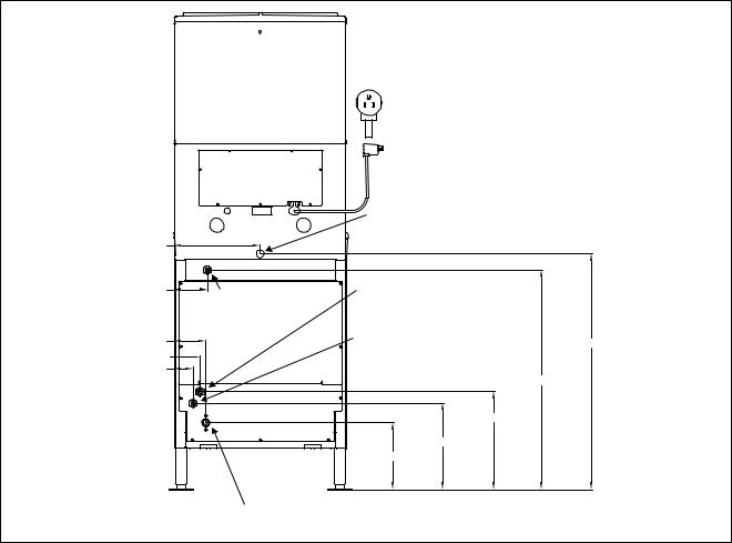
Fig. 1 – Rear connections, freestanding models |
|
|
|
|
|
power cord |
|
|
|
NEMA 5-15 |
|
|
access panel |
|
|
|
|
3/4" MPT drain |
|
12.25" (31.2 cm) |
|
|
|
4.75" (11.9 cm) |
3/8" FPT |
3/8" FPT condenser outlet location |
|
|
water inlet |
(water-cooled only) |
|
4.5" (11.4 cm) |
|
3/8" FPT condenser outlet location |
33.75" (85.8 cm) |
|
(water-cooled only) |
||
3.75" (9.3 cm) |
|
|
|
|
|
|
|
2.75" (6.8 cm) |
|
31.5" (80 cm) |
|
|
|
||
|
|
14" (35.7 cm) |
|
|
|
12.38" (31.4 cm) |
|
|
|
9.62" (24.4 cm) |
|
3/4" MPT ice machine drain location
10.Remove top front cover by removing two screws at bottom corners of cover.. Lift cover slightly and pull forward..
11.If dispenser is equipped with SensorSAFE remove protective plastic coating from dispense sensor labels..
12.Turn on dispenser power and bin signal rocker switches.. Check dispenser and ice machine operation..
13.Sanitize ice machine according to instructions in ice machine manual.. Discard ice made during sanitizing process..
14.Turn off ice machine bin signal switch..
15.Remove dispenser hopper lid; sanitize dispenser according to instructions beginning on page 12..
16.Turn ice machine bin signal switch on and replace front covers, securing with screws..
6 |
100CR/CT/FB Ice and Water Dispensers |
Installing countertop dispensers


 CAUTION!
Dispensers with top mount ice machines cannot be mounted on legs.. They must be bolted to counter.. Use gloves when lifting ice machine to protect hands from sheet metal edges..
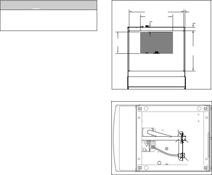
1.Position dispenser in desired location, mark dispenser outline on counter and remove dispenser..
2.Regardless of whether utilities will exit through back or bottom of dispenser, drill four (4) 3/8" holes in counter to anchor dispenser to counter (Fig. 2)..
Follett countertop dispensers can have any or all utilities run directly through counter or out rear of dispenser. For dispensers with any utilities exiting through counter, make counter cut-out (Fig. 2).
3.For utilities exiting through bottom only:
(a)Make cut out as shown in
Fig. 2.
(b)Move drain fitting from back of dispenser and mount where shown in Fig. 3..
(c)Cut drain tube to length and attach to barbed connection..
(d)Move inlet water fitting from back of dispenser and mount where shown in Fig. 3..
(e)Cut water tubing to length and re-insert into water fitting..
4.If ice transport tube will exit out rear of dispenser, remove ice transport tube knockout from rear of dispenser.. Install supplied
grommet for CR models..
Note: Utility connections can be accessed through front of dispenser by removing stainless steel splash panel, or by removing access panel (Fig. 4) on back of dispenser.
Fig. 2
|
UNDERSIDE VIEW OF DISPENSER |
|
|
23.63" (60.0 cm) |
0.44" |
|
14.00" (35.6 cm) |
(11 mm) |
|
|
|
|
2.00" (5.1 cm) |
1.50" |
|
|
|
|
|
(3.8 cm) |
9.25" |
CUTOUT |
|
(23.5 cm) |
|
|
|
|
|
|
|
17.31" |
|
|
(44.0 cm) |
Fig. 3 – Bottom exiting utilities (countertop units)
bracket |
|
drain tube |
drain |
|
tting |
|
inlet |
|
tting |
100CR/CT/FB Ice and Water Dispensers |
7 |

Fig. 4 – Rear connections, countertop models
8.22" (201 cm) |
6.06" (15.5 cm) |
44.97" (114 cm) |
41.97" (106 cm)
38.97" (99 cm)
35.91" (91 cm)
 ACCESS PANEL
CONDENSER INLET 3/8" NPT FEMALE
WATER COOLED ONLY
CONDENSER OUTLET 3/8" NPT FEMALE WATER COOLED ONLY
POTABLE WATER INLET 3/8" NPT FEMALE
DRAIN
3/4" NPT MALE
|
|
|
|
|
|
|
|
|
|
|
|
|
|
|
|
|
|
|
|
|
|
|
|
|
|
|
|
|
|
|
|
|
|
|
|
|
|
|
|
|
|
|
|
|
|
|
|
|
|
|
|
|
|
|
|
|
1.34" (35 mm) |
|
|
|
|
|
|
|
|
|
|
|
|
|
0.78" (20 mm) |
||||
|
|
|
|
|
|
|||||||||||||
|
|
|
|
|
|
|
|
|
|
|
|
|
||||||
8.22" (20.8 cm) |
|
|
|
|
|
|
|
|
|
|
|
|
|
|
|
|
||
|
|
|
|
|
|
|
|
|
|
|
|
|
|
|
DRAIN |
|||
|
|
|
|
|
|
|
|
|
|
|
|
|
|
|
||||
12.25" (31 cm) |
|
|
|
|
|
|
|
|
|
|
|
|
|
|
|
3/4" NPT MALE |
||
|
|
|
|
|
|
|
|
|
|
|
||||||||
|
|
|
|
|
|
|
|
|
|
|
|
|
|
|
|
|
WATER INLET |
|
|
|
|
|
|
|
|
|
|
|
|
|
|
|
|
|
|||
|
|
|
|
|
|
|
|
|
|
|
|
|
|
|
|
|
(INTERNAL) |
|
|
|
|
|
|
|
|
|
|
|
|
|
|
|
|
|
|
3/8" NPT FEMALE |
|
5.If power is to be supplied through counter cut-out, complete steps 6-9.. If power is to be supplied through rear of dispenser, proceed to step 10..
6.Temporarily remove rear access panel (Fig. 4) from rear of dispenser..
7.Loosen junction box mounting screws.. Lift junction box and power cord up until cord and mounting screws clear notches on rear panel of dispenser.. Remove Phillips head screws from right side of junction box..
8.Rotate junction box 90 degrees so that screw holes on right side of junction box align with holes on rear dispenser panel.. Resecure junction box to dispenser using Phillips head screws..
9.Place power cord inside dispenser and replace access panel (Fig. 4) to rear of dispenser..
Note: For dispensers to be installed with utilities connected through rear of dispenser, it may be easier to make preliminary connections before dispenser is set in place..
10.Apply a thick bead, approximately.. 1/4" (6 mm) diameter, of NSF listed silicone sealant (Dow-Corning* RTV-732 or equivalent) 1/4" (6 mm) inside marked outline of dispenser..
11.Carefully position dispenser on counter..
12.Remove four screws securing splash panel to front of dispenser and gently lay splash panel on counter.. (Water line to solenoid valve can be disconnected from water inlet valve by pushing on ring at end of inlet fitting while pulling on tubing..)
13.Secure dispenser to counter with four 3/8" bolts (supplied by others)..
14.Smooth excess sealant around outside of dispenser..
15.Proceed with either RIDE or top-mounted ice machine connection instructions, as appropriate..
*Dow Corning is a registered trademark of Dow Corning Corporation in the United States and other countries
8 |
100CR/CT/FB Ice and Water Dispensers |

Installing RIDE ice machines


 CAUTION!
See Ice Machine Installation Manual (form #01062587) for critical installation instructions for RIDE ice machines.. Failure to comply with these instructions will result in poor performance and void warranty..
1.Install RIDE ice machine following instructions in ice machine manual..
2.If dispenser is equipped with SensorSAFE remove protective plastic coating from dispenser lenses..
3.Remove top front cover by removing two screws at bottom corners of cover.. Lift cover slightly and pull forward.. Turn on power and bin signal rocker switches.. Replace front cover and secure with screws.. Test operation..
4.Sanitize ice machine following instructions in ice machine manual.. Discard ice made during sanitizing process..
5.Sanitize dispenser hopper following instructions on page 12.. Installation is complete..
Fig. 5 – Ice transport tube and ice level control stat mounting for freestanding dispensers and countertop units with RIDE ice machine
ice level control stat |
1.00" |
|
|
|
engaging pin |
||||||||||||||||||||
|
|
|
|
|
|
|
|
|
|
|
|||||||||||||||
|
|
|
|
|
|
|
|
|
|
|
|
|
|
(25.4 |
cm) |
|
ice tube |
||||||||
|
|
|
|
|
|
|
|
|
|
|
|
|
|
|
|
|
|
||||||||
|
|
|
|
|
|
|
|
|
|
|
|
|
|
|
|
|
|
|
|
|
|
|
|
|
|
|
|
|
|
|
|
|
|
|
|
|
|
|
|
|
|
|
|
|
|
|
|
|
|
|
|
|
|
|
|
|
|
|
|
|
|
|
|
|
|
|
|
|
|
|
|
|
|
|
|
|
|
ice hose mounting bracket
0.187 (5 mm) ice tube hole
100CR/CT/FB Ice and Water Dispensers |
9 |

Installing top mount ice machines
Models 110CT425A/W


 CAUTION!
Dispensers with top mount ice machines cannot be mounted on legs.. They must be bolted to counter.. Use gloves when lifting ice machine to protect hands from sheet metal edges.. See Ice Machine manual..
1.Remove dispenser top front cover by removing two screws at bottom corners of cover, lifting cover slightly and pulling forward..
2.Remove ice machine compartment top and side panels..
3.Remove ice machine hold-down bracket from front of ice machine compartment..
4.Lift ice machine onto dispenser top and slide ice machine completely into position, compressor end first..
5.Reinstall hold-down bracket on front of ice machine with power cord and bin signal cords in notch.. Do not cut or pinch cords..
6.Insert loose end of ice transport tube through bracket (on ice machine base) into hopper access hole.. Tighten transport tube clamp screw to secure ice transport tube..
7.Connect plastic water supply line to water fill solenoid..
1
|
2 Tighten clamp |
1.00" (2.54 cm) |
screw |
|
10 |
100CR/CT/FB Ice and Water Dispensers |

8. Connect molded drain tube to evaporator drain pan, purge solenoid and rear drain fitting..
ICE
NOZZLE
EVAPORATOR
DRAIN PAN
TO DRAIN CUP 
|
RESERVOIR FILL |
|
SOLENOID |
WATER |
WATER SUPPLY |
RESERVOIR |
3/8" FPT, 45-90 F (7-32 C) |
|
10-70 PSI (69-483 KPA) |
9.Connect dispenser bin signal cable to two-pin receptacle on the ice machine electrical box and connect the three-pin receptacle to the ice machine electrical box ..
2 |
1 |
10.On dispensers equipped with water-cooled ice machines, connect condenser water supply and drain lines to condenser fittings on ice machine..
11.Turn on water supply and check for leaks..
12.Plug dispenser power cord into 15A rated NEMA 5-15 circuit..
13.If dispenser is equipped with SensorSAFE, remove protective plastic coating from dispense sensor labels..
14.Turn on power and bin signal rocker switches and test operation..
15.Sanitize ice machine following instructions in ice machine manual..
16.Remove dispenser hopper access lid and sanitize dispenser according to instructions on page 12..
17.Replace front cover and secure with screws.. Installation is complete..
ice level control thermostat
0.75" (19 mm)
Hand bend cap tube end to approximately 45° as shown
45°
100CR/CT/FB Ice and Water Dispensers |
11 |
 Loading...