


12CI400A
Installation, Operation and Service Manual
208595R09
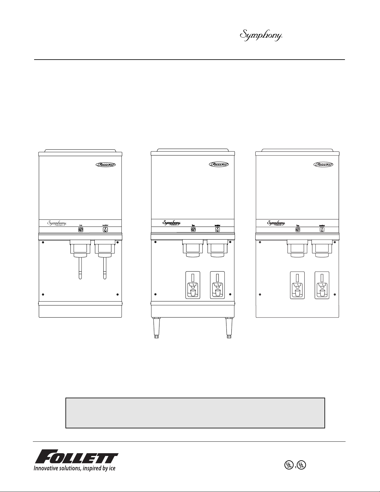
12CI400A
countertop dispenser
12CI400A
countertop dispenser with
SensorSAFE
™
actuation
(shown with legs accessory)
12HI400A
wall mount dispenser (available
with or without drain pan)
Following installation, please forward this manual
to the appropriate operations person.
801 Church Lane • PO Box D, Easton, PA 18044, USA
Toll free (800) 523-9361 • (610) 252-7301
Fax (610) 250-0696 • www.follettice.com
12 Series
Ice and Water Dispensers
Order parts online
www.follettice.com

Welcome to Follett Corporation
Important cautions
Specifications
Installation
Installing countertop dispensers without legs
Installing countertop dispenser with legs accessory
Installing wall mount dispensers
User information
Cleaning and sanitizing procedures
Dispenser cleaning
Icemaker cleaning and sanitizing
Start-up following cleaning
Service information
Wiring diagram – lever model
Wiring diagram – SensorSAFE
™
model
Icemaker operational and diagnostic sequences
Refrigeration cycle diagram
Icemaker capacity chart
Icemaker data
Refrigeration system data and requirements
Dispenser troubleshooting – lever models
Dispenser troubleshooting – SensorSAFE models
Icemaker troubleshooting
Disassembly and replacement instructions
Replacement parts
2
Table of contents
Follett Corporation
Equipment Return Policy
Follett equipment may be returned for credit under the following conditions:
1. The equipment is new and unused.
2. A return authorization number has been issued by customer service within 30 days after shipment.
3. Follett receives the equipment at the factory in Easton, PA within 30 days after issuance of the return authorization number.
4. The equipment must be returned in Follett packaging. If the packaging has been damaged or discarded, Follett will forward, at the customer’s
expense, new packaging.
Note: Return freight charges are the responsibility of the customer. If equipment is returned and is damaged because of improper packaging, Follett
Corporation will not be held responsible.
Credit will be issued when:
The equipment has been inspected by Follett and deemed suitable to be returned to stock.
Note: A 15% restocking charge will be deducted from the credit. If the cost to return the product to stock exceeds 15%, the actual cost will be deducted.
3
3
4
5
5
6
7
10
10
10
11
12
13
14
15
16
21
22
22
23
24
25
26
28
32
12CI400A
Condenser type, A = air-cooled
Icemaker capacity in lbs per day
Icemaker location, I = integral
Dispenser configuration, C = countertop, H = wall mount
Approximate storage capacity in lbs
Welcome to Follett
Follett equipment enjoys a well-deserved reputation for excellent performance, long-term reliability and
outstanding after-the-sale support. To ensure that this equipment delivers that same degree of service, we ask
that you take a moment to review the installation portion of this manual before beginning to install the unit. Our
installation instructions are designed to help you achieve a trouble-free installation. Should you have any
questions or require technical help at any point, please call our technical service group at (800) 523-9361 or
(610) 252-7301.
Before you begin
After uncrating and removing all packing material, inspect the equipment for concealed shipping damage. If
damage is found, notify the shipper immediately and contact Follett Corporation so that we can help in the filing of
a claim, if necessary.
Check your paperwork to determine which model you have. Follett model numbers are designed to provide
information about the type and capacity of Follett ice dispensing equipment. Following is an explanation of the
different model numbers.
Important cautions
!
• Do not tilt any unit further than 30° off vertical during uncrating or installation
• Dispenser bin area contains mechanical, moving parts. Keep hands and arms clear of
this area at all times. If access to this area is required, power to unit must be
disconnected first.
• Follett recommends a Follett QC4-FL4S water filter system (item# 00130299) be
installed in the icemaker inlet water line
• Prior to operation clean and sanitize the dispenser in accordance with instructions found in
this manual
• Ice is slippery. Be sure counters and floors around dispenser are clean, dry and free of ice.
• Do not block right side air intake or top air exhaust
Specifications
Electrical
115V, 60Hz, 1 phase, 13.0 amps. Connect to 20 amp circuit, fuse or breaker.
Note: It is preferred that circuit be protected by a GFCI.
Furnished with 6 ft (1.8m) power cord with a 90° hospital grade 5-20 plug
Ambient
Air temp 100°F/38°C Max. 50°F/10°C Min. (Best performance below 80˚F/27˚C)
Water temp 90°F/32°C Max. 40°F/4°C Min. (Best performance below 70˚F/21˚C)
Water pressure 70 P.S.I. Max. 10 P.S.I. Min.
Plumbing
12CI400A 12HI400A
Dispenser drain 3/4" FPT 3/4" FPT
Water inlet 3/8" FPT 3/8" FPT
Note: Water shut-off recommended within 10 feet (3m) of dispenser. Drain to be hard-piped and insulated.
Maintain at least 1/4" per foot (20mm per 1m run) of slope.
Ventilation clearances
6" (153mm) on right side of dispenser, 6" (153mm) at top for ventilation and 12" (305mm) at top recommended
for service.
Note: Do NOT block right side air intake or top air exhaust.
Dry weight
175 lbs (79.4kg)
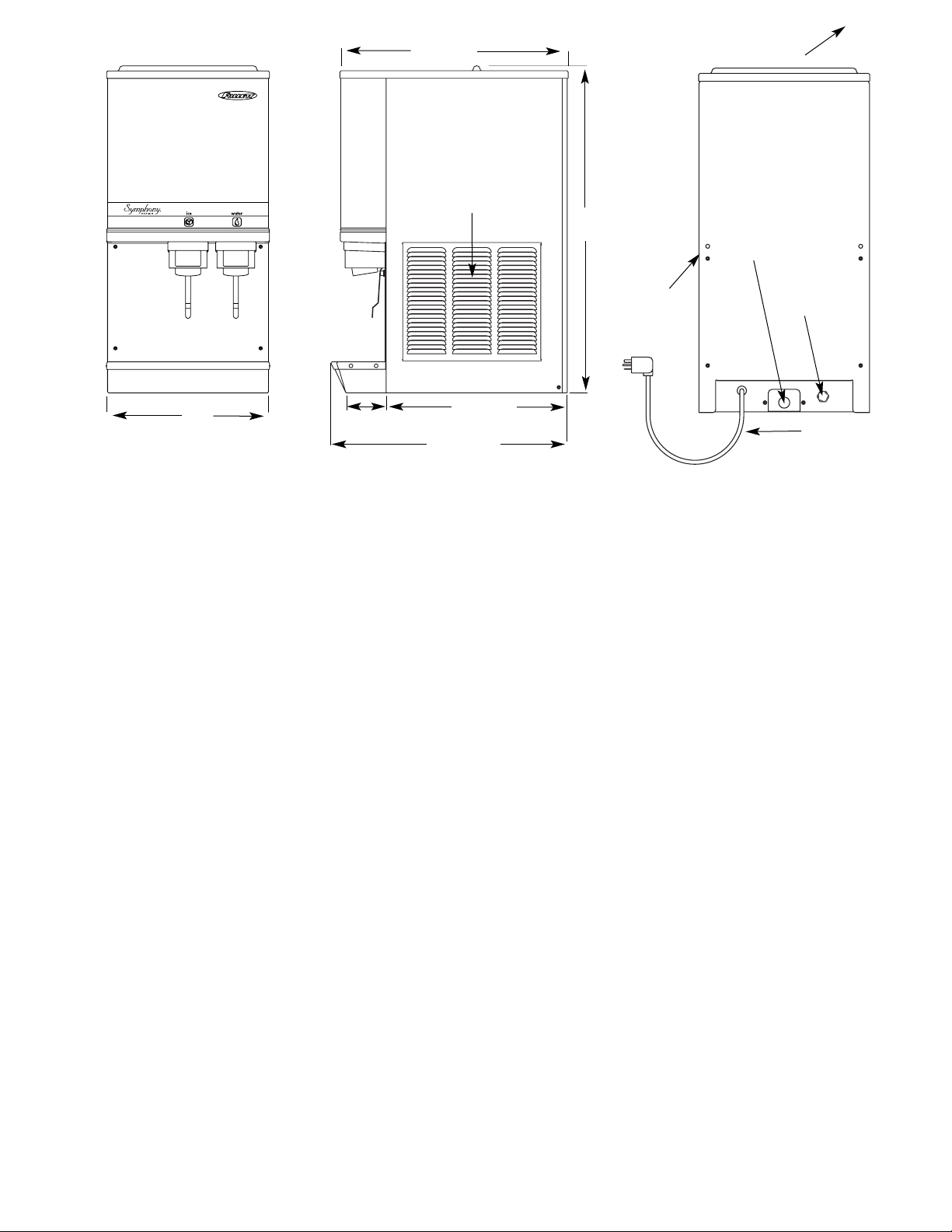
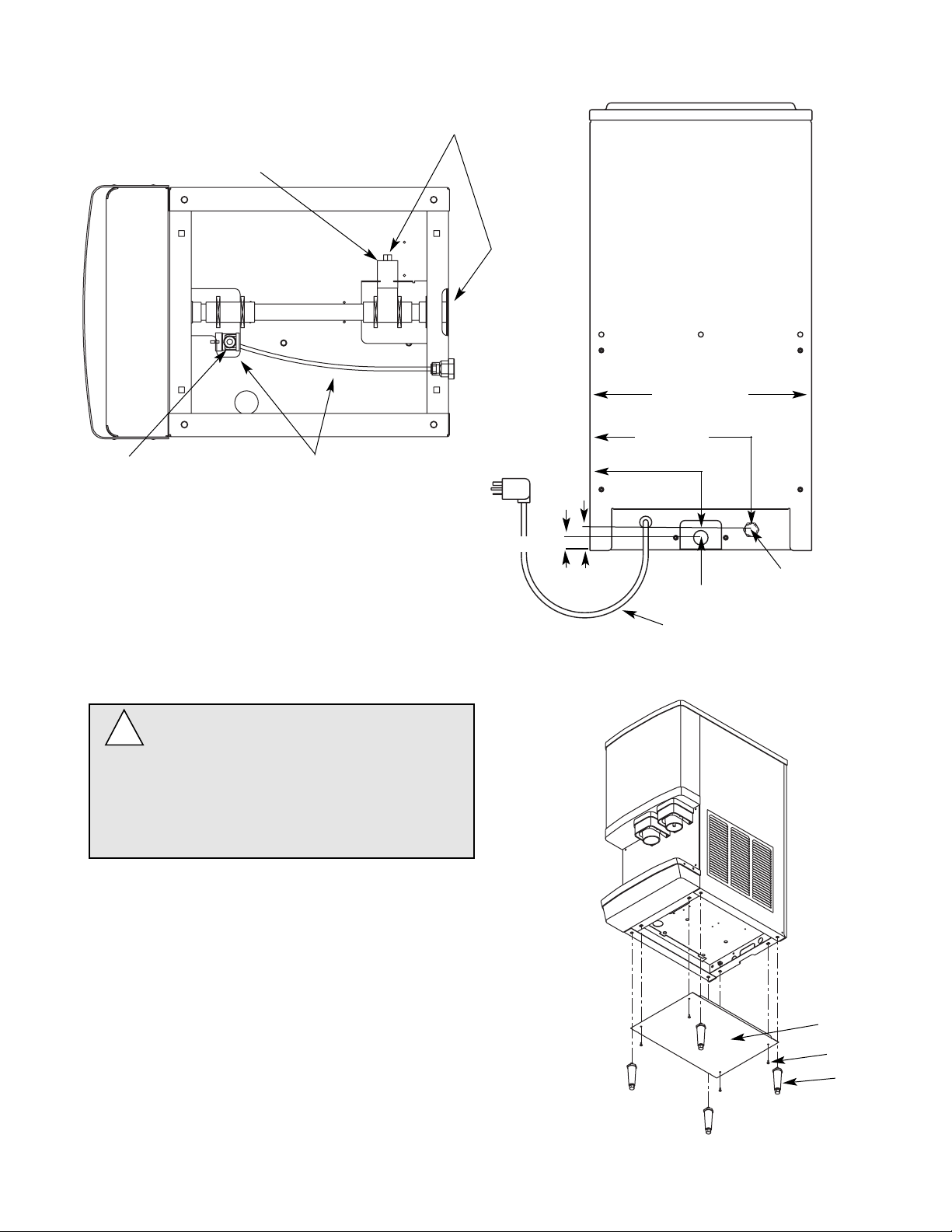
Dispenser front view
Dispenser side view
Dispenser rear view
Air
intake
air exhaust
air
intake
power cord
3/4" FPT drain
3/8" FPT
water inlet
16"
(407mm)
22.625"
(575mm)
32.5"
(826mm)
4"
(102mm)
18"
(458mm)
23.5"
(597mm)
4
5
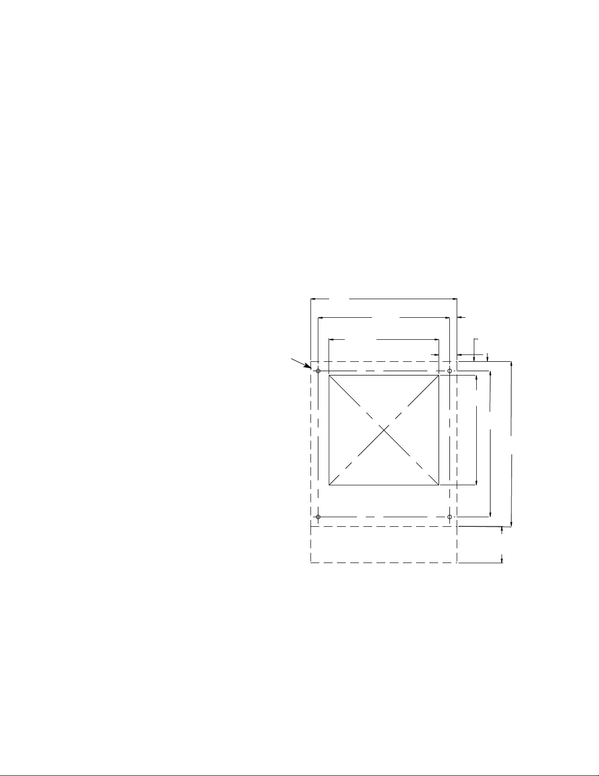
Installing countertop dispensers without legs
1. Position dispenser in desired
location, mark dispenser outline
on counter and remove dispenser.
2. Regardless of whether utilities will
exist through back or bottom of
dispenser, drill four (4) 7/16" holes
in counter to anchor dispenser to
counter (Fig. 1).
3. For utilities existing through
bottom only:
(a) Make cut out as shown in
Fig. 1.
(b) Move plug from drain T to
back of unit (Fig. 2).
4. For all units: Apply a thick bead
approximately 1/4" (6mm)
diameter of NSF listed silicone
sealant (Dow Corning RTV-732 or
equivalent) 1/4" (6mm) inside
marked outline of dispenser.
5. Carefully lower dispenser on
counter in proper position and
secure to counter with four (4)
3/8"-16NC bolts.
6. Smooth excess sealant around
outside of dispenser.
cutout for
connections
through bottom
(404mm)
(458mm)
(102mm)
(39mm)
(305mm)
(305mm)
(366mm)
(407mm)
(21mm)
2" (51mm)
16"
14.4"
12"
0.8"
1.5"
12"
15.9"
18"
4"
1" (26mm)
Fig. 1 – Counter information
437" (12mm)
diameter
Installation
Before you begin
All dispensers must be installed level in both directions to ensure proper operation.
Service and ventilation clearances: 6" (153mm) on right side of dispenser, 6" (153mm) at top for ventilation and
12" (305mm) at top recommended for service.
Countertop units installed without legs provide the option of taking utilities out bottom or back of dispenser (on
wall mount units and countertop units with legs, utilities exit from back). See counter cutout drawings for bottom
exiting utilities on units with and without drain pans. For installations where utilities exit through back of dispenser,
refer to back view drawings.
Wall mount models without drain pan are designed for use above sinks.
Counter depth must allow front of sink to be a minimum of 23.5 (597mm) from wall.
3/8" FPT water inlet
3/4" FPT drain
power cord
Fig. 3 – Rear exiting utilities
(countertop units)
3/4" FPT drain
3/8" OD push-in
water inlet
Remove poly tubing and
fitting for water inlet
bottom
panel
screw
leg
Do NOT tilt unit farther than 30˚ off
vertical plane.
Countertop dispensers that sit on legs
(not bolted to counter) can be
inadvertently moved. Care should be
taken when operating and cleaning to
avoid accidents.
!
Fig. 2 – Bottom exiting utilities
(countertop units)
Fig. 4 – bottom panel assembly
1. Carefully tip dispenser back to expose underside
and block up in place.
2. Screw legs (shipped taped to drain pan of
dispenser) into dispenser bottom, taking care to
seat legs securely against underside of dispenser.
3. Attach bottom panel and hardware to bottom of
dispenser with supplied screws (Fig. 4).
4. Position unit in desired location and adjust bullets
on legs to level in both directions.
5. Make final connections.
Installing countertop dispensers
with legs accessory
16" (407mm)
11.7"
(298mm)
8.1"
(206mm)
1.5"
(39mm)
.9" (23mm)
6
Move pipe plug
to back of unit
7
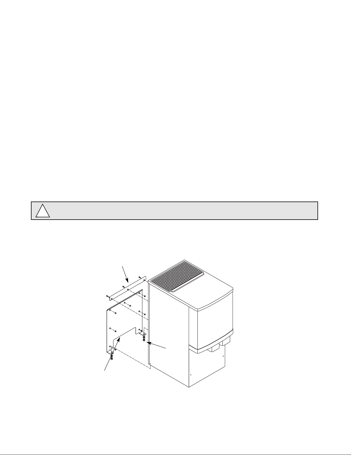
Installing wall mount dispensers
Notes:
No drain pan is provided since the dispenser is intended to be installed above a sink. (Contact Follett if a drain
pan is desired.)
SensorSAFE actuation is standard. (Contact Follett if lever actuation is desired. A deeper cabinet will be needed.)
Recommended minimum counter depth and mounting height shown on Fig. 7 ensures that ice will drop into sink.
See Fig. 6 for model dimensions. The dimensions include the .5" (13mm) mounting bracket supplied with the unit.
1. Cut utility hole in wall as shown (Fig. 10).
2. Mount support bracket to wall using fasteners of sufficient strength (fasteners not included, see Fig. 6).
3. Rough in water and drain lines (Fig. 10).
4. Lift dispenser onto support bracket, positioning unit so that hook on back of dispenser is captured by support
bracket angle (Fig. 7).
5. Install two (2) supplied 3/8"-16NC screws through bottom of support bracket into bottom of dispenser (Fig. 5).
6. Make final connections.
7. Attach bottom panel and hardware to bottom of dispenser (Fig. 8).
wall mounting
bracket
screw
support
bracket
Fig. 5 – Wall mount bracket and fastener requirements
WALL PREPARATION: Wall and fasteners must be of sufficient strength to carry weight of unit
(185 lbs (83.9kg)). Hardware for this is not included.
!
(254 mm)
(407mm)
(77mm)
(77mm)
(204mm)
(166mm)
(331mm)
1.4" (36mm)
(178mm)
(356mm)
.437
10"
16"
3"
7"
14"
3"
13"
6.5"
8"
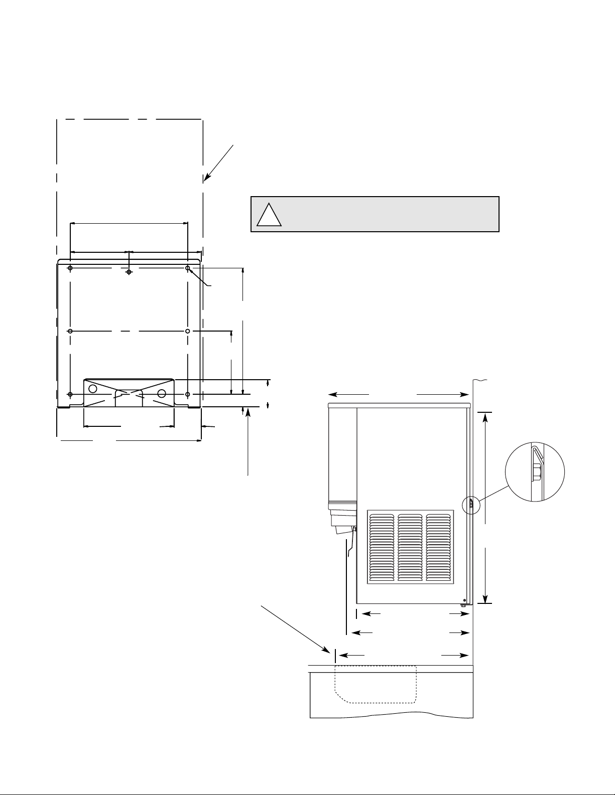
Fig. 6 – Wall mounting dimensions
bottom of dispenser
outline of
dispenser
Caution: Do NOT rest dispenser weight on
bottom of support bracket.
!
Fig. 7 – Wall mount side view
22.5"
(572mm)
32.5"
(826mm)
18.5" (470mm)
Installing wall mount dispensers
19.375" (493mm)
23.5" (597mm)
minimum distance
to sink front
8
9
outline of dispenser
support bracket
bottom of
dispenser
utility cutout
in wall
3/4" copper
drain tube
3/8" copper
water tube
locate tubing
within dimension shown
water and
drain tubing
(407mm)
(77mm)
3"
(254mm)
3.5"
3"
(77mm)
1.25" (32mm) MAX
(77mm) (89mm)
(77mm)
MIN.
0.88" (23mm) MIN
16"
10"
3"
3"
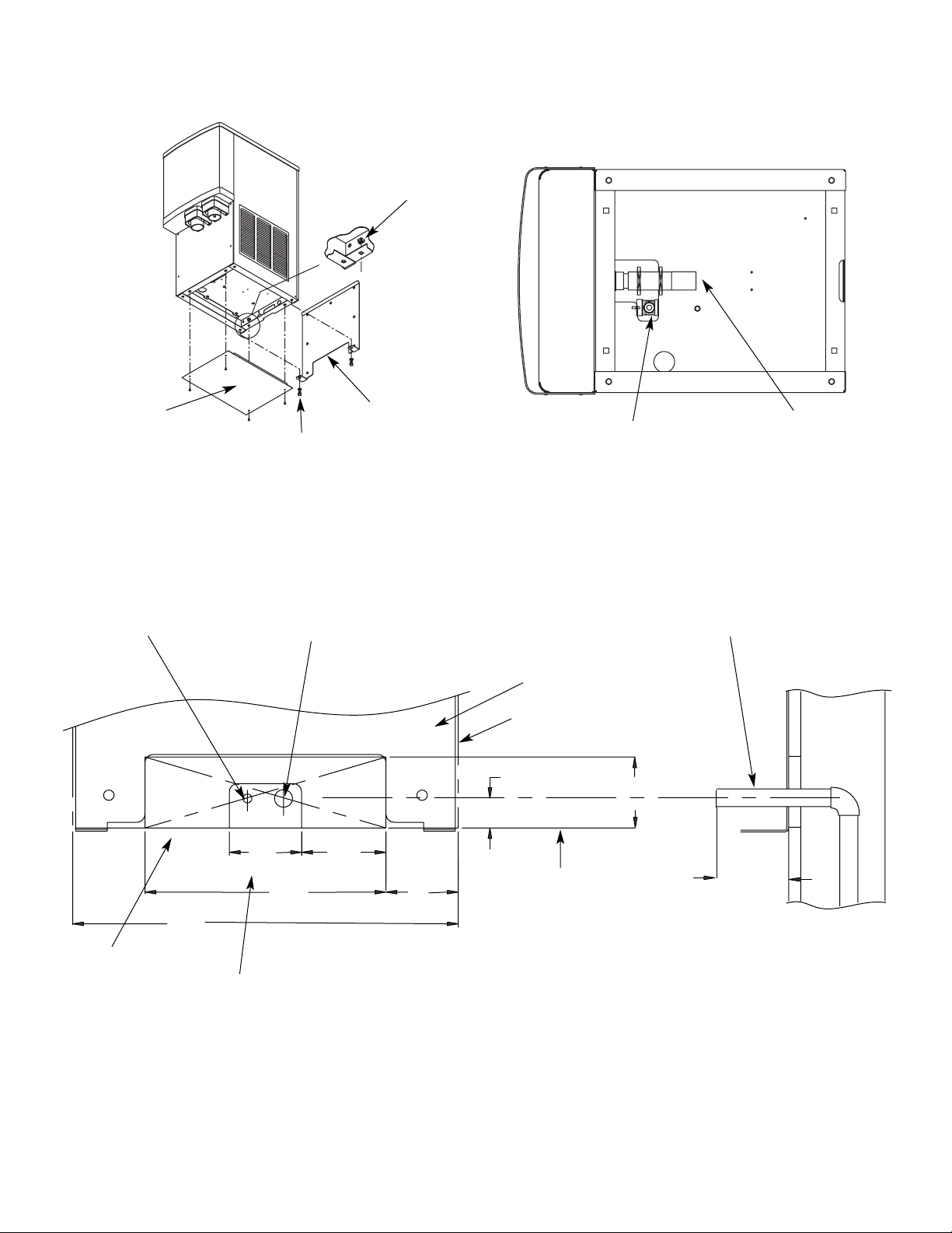
nut
support bracket
screw
bottom panel
3/4" FPT drain
3/8" OD push-in
water inlet
Fig. 8 – Wall mount unit bottom panel assembly
Fig. 9 – Wall mount bottom view
Fig. 10 – Front view of wall mount bracket, utility location
Side view of utilities exiting wall
wall
10
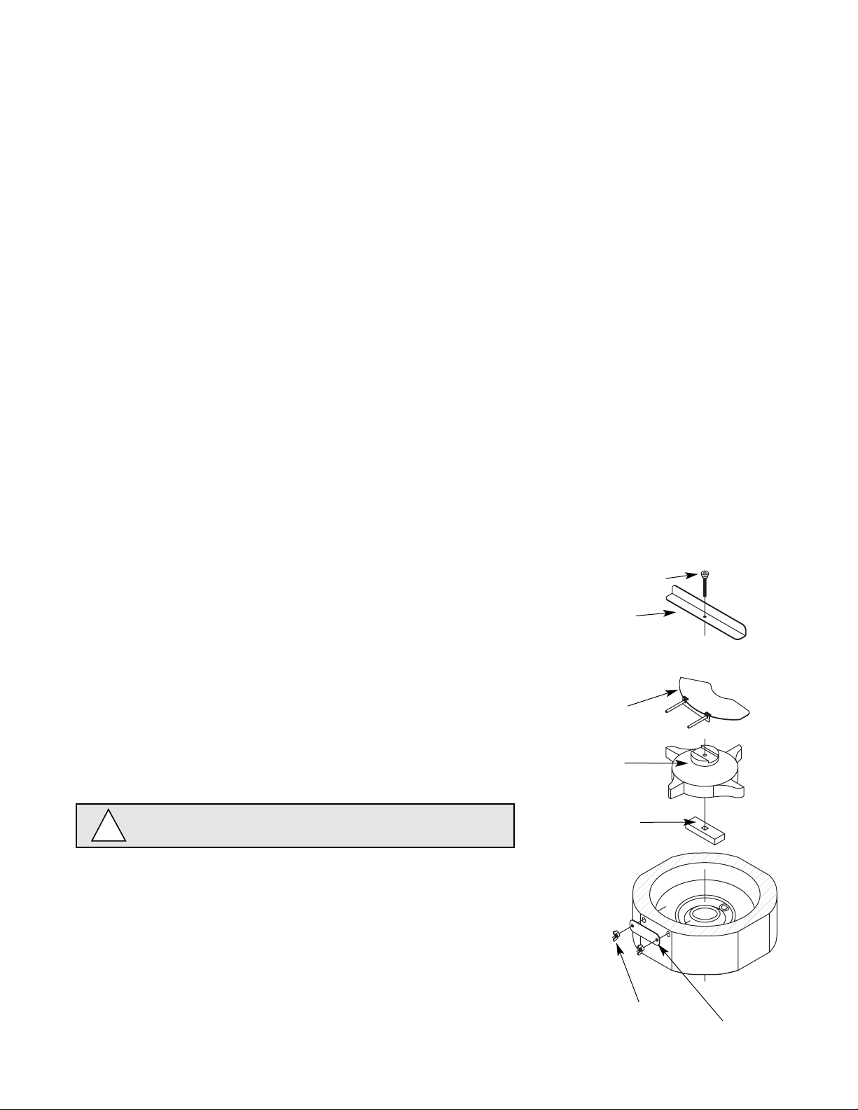
Dispenser cleaning: start-up and quarterly intervals
1. Remove all ice from storage hopper.
2. Remove top and front cover (see page 30).
3. Remove center thumbscrew, locking plate, two wingnuts and
backing plate from front of storage hopper.
4. Remove stud assembly, agitator, spacer, baffle, wheel and drive
bar in this sequence.
User information
How the dispenser works
Follett’s 12 series automatic-load ice and water dispensers are equipped with Follett’s 400 lb (181kg)/day
icemaker. In the continuous icemaking process, water freezes to the inside wall of the evaporator. A rotating
stainless steel auger carries the ice to the top of the evaporator where it is compressed and extruded through an
outlet port. The ice is then pushed through a tube to the storage hopper. When the hopper is full, a bin thermostat
opens and shuts the icemaker off. When the dispense mechanism is activated, a dispense motor is turned on,
causing the wheel to turn. This moves ice to the dispense chute where it drops by gravity into the container held
below the chute.
How the SensorSAFE accessory works
Follett’s SensorSAFE accessory maximizes sanitation and minimizes the possibility of cross-contamination by
eliminating physical contact between the cup or container and dispenser. Sensors in the panel use reflected
infrared light to detect the presence of the container and send a signal to a control board which then activates the
appropriate components for ice or water dispensing.
The SensorSAFE package includes a cleaning switch under the left side of the front cover which
temporarily shuts off dispensing to allow cleaning of the panel and lenses. If the switch is not turned back on after
cleaning, the dispenser automatically resets after two minutes for normal operation.
SensorSAFE also includes a time limit safety feature which automatically stops ice dispensing after
one minute of continuous dispensing. Dispensing can be resumed by moving the container away from
the dispenser and returning it to the activation zone.
Cleaning and sanitizing procedures
Solution A: Prepare cleaning solution (200 ppm of available
chlorine content) of Ecolab Mikro-chlor Cleaner or
equal chlorinated detergent. Solution temperature
must be 75˚F – 125˚F (24˚C – 52˚C).
Solution B: Prepare sanitizing solution (50 ppm of available
chlorine content) of Ecolab Mikro-chlor Cleaner or
equal chlorinated detergent. Solution temperature must
be 75˚F – 125˚F (24˚C – 52˚C).
Follett recommends the periodic cleaning schedule below to ensure the
quality of ice provided. Use only recommended cleaning solutions. Do
not use solvents, abrasive cleaners, metal scrapers or sharp objects.
Warning – Always disconnect power before cleaning.
!
stud assembly
agitator
wheel
drive bar
baffle
backing
plate
wingnut

5. Remove dispense chute.
6. Wipe lid, wheel, baffle, inside of storage area and dispense chute with damp cloth wrung out in Solution A.
Note: To avoid possible damage to motor assembly, use a damp cloth only to clean storage hopper. Do not
allow water to run through center hole in bottom of hopper.
7. Rinse all above items with damp cloth and wring out in clear water.
8. Sanitize all above items with damp cloth wrung out in Solution B. Do not rinse.
9. Pour 1 cup (284ml) household bleach into drain pan, followed by 1 gallon (3.8L) hot tap water to flush
drains.
10. Reinstall all parts.
Dispenser grille and drain pan – weekly intervals
1. Remove grille and wash with Solution A. Rinse thoroughly.
2. Pour 1 cup (282ml) household bleach into drain pan, followed by 1 gallon (3.8L) of hot tap water to flush
drains.
Splash panel front, SensorSAFE dispensers
1. Deactivate dispensing by pressing and releasing clean switch located on left side of unit under top front
cover.
2. Clean lens using a soft cloth and mild, non-abrasive, non-chlorine based
cleaner.
3. Reactivate dispensing by pressing and releasing clean switch again.
Icemaker cleaning & sanitizing
Periodic cleaning of Follett’s icemaker system is required to ensure peak performance and delivery of
clean,sanitary ice. The recommended cleaning procedures which follow should be performed at least as
frequently as recommended below and more often if environmental conditions dictate.
Cleaning of the condenser can usually be performed by facility personnel. Cleaning of the icemaker system in
most cases should be performed by your facility’s maintenance staff or a Follett authorized service agent.
Regardless of who performs the cleaning, it is the operator’s responsibility to see that this cleaning is performed
according to the schedule below. Service problems resulting from lack of preventive maintenance will not be
covered under the Follett warranty.
Cleaning procedures
Recommended monthly cleaning of condenser (air-cooled icemaker only)
1. Use a vacuum cleaner or stiff brush to carefully clean condenser coils of air-cooled icemakers to ensure
optimal performance.
2. When reinstalling counter panels in front of remote icemakers, be sure that ventilation louvers line up with
condenser air duct.
Recommended semi-annual cleaning of icemaking system
Icemaking system can be cleaned in place without disassembling water system. Cleaning should be performed
at least every 6 months, and more often if local water conditions dictate.
1. Disconnect power to icemaker.
2. Remove any icemaker panels required to gain access to water reservoir and electrical control box.
3. Turn compressor switch on electrical box of icemaker to OFF position.
4. Remove water reservoir cover and block up reservoir float or close water supply valve.
5. Drain water from reservoir by releasing evaporator drain line from float reservoir bracket and removing plug
from drain line.
11

12
6. Following manufacturer’s instructions, prepare one gallon (3.8L) of Follett SafeCLEAN Ice Machine Cleaner
(one 7 oz packet) or equivalent. Solution temperature must be at least 120° F (48.9° C).
WARNING: Most ice machine cleaners contain citric or phosphoric acid that can cause skin irritation. Read
caution label on product and follow instructions carefully.
7. Plug drain hose, replace drain line in reservoir bracket and pour part of cleaning solution into reservoir, filling
it almost to overflowing.
8. Remove stainless steel compression nozzle and drain lines. Submerge in a cup of cleaning solution while
cleaning rest of system. (Flake icemakers have no compression nozzle and drain lines.)
CAUTION: To avoid potential pitting, do not soak parts in SafeCLEAN for more than 45 minutes.
9. Restore power to icemaker (gearmotor will run; compressor and fan will not).
10. After 15 minutes, turn power OFF; drain solution from reservoir and evaporator.
11. Fill reservoir almost to overflowing with clean, 120° F (48.9° C) water, and drain. Repeat three times.
12. Following manufacturer’s instructions, prepare 1 gallon (3.8L) of 200ppm 5.25% Sodium Hypochlorite
solution (mix 1 oz household bleach to 2 gallons water) or equivalent. Solution temperature must be at least
120° F (48.9° C).
13. Rinse compression nozzle in clean water and submerge in a cup of sanitizing solution while following steps
14-19.
14. Connect ice transport tube directly onto evaporator outlet port without compression nozzle.
NOTE: If bin will not be cleaned at this time, place a large pan in bin storage area to catch ice or connect a
separate ice transport tube to evaporator and divert ice into separate container.
15. Fill reservoir almost to overflowing with sanitizing solution.
16. Restore power to icemaker (gearmotor will run; compressor and fan will not).
17. After 10 minutes, turn compressor switch to ON position.
18. As unit starts to make ice, continue to pour sanitizing solution into reservoir, maintaining level just below
reservoir overflow.
19. Continue to make ice with sanitizing solution for 20 minutes.
20. Turn power to icemaker OFF.
21. Disconnect transport tube from evaporator outlet port. Rinse compression nozzle in clean water and reinstall
on evaporator outlet. Reconnect transport tube to compression nozzle.
22. Drain any remaining sanitizing solution from evaporator.
23. Fill reservoir almost to overflowing with clean, 120° F (48.9° C) water, and drain. Repeat three times.
24. Unblock float (or open water supply valve) and replace reservoir cover; restore power to icemaker and
ensure compressor switch is in ON position. Make ice for at least 15 minutes to flush any remaining
solution from system (remote icemakers with long ice transport hoses may take longer to flush out). Discard
this and all ice made during sanitizing.
25. Inspect evaporator drain pan and drain line and remove any accumulated scale build up.
26. Replace any panels removed prior to cleaning.
Start-up following cleaning
1. Clean and sanitize ice storage area of dispenser in accordance with instructions above before making ice.
2. Turn icemaker on and begin to make ice (icemaker should start immediately with power and bin signal
supplied).
3. After approximately 30 minutes, test dispenser for proper dispensing.
 Loading...