


 Loading...
Undercounter Ice and Water Dispenser with Chewblet® Ice Machine
7UC100A, 7UD100A
Installation, Operation and Service Manual
Serial numbers E01087 and above
7UC100A |
7UD100A |
Following installation, please forward this manual to the appropriate operations person.
801 Church Lane • Easton, PA 18040, USA |
Order parts online: |
Toll free (877) 612-5086 • +1 (610) 252-7301 |
www.follettice.com |
www.follettice.com |
00966879R08 |

2 Undercounter Dispenser and Ice machine 7UC100A/7UD100A

Contents |
|
Welcome. . . . . . . . . . . . . . . . . . . . . . . . . . . . . . . . . . . . . . . . . . . . . . . . . . . . . . . . . . . . . . . . . . . . . . . . . . . . . . . . . . . . . |
4 |
Before You Begin. . . . . . . . . . . . . . . . . . . . . . . . . . . . . . . . . . . . . . . . . . . . . . . . . . . . . . . . . . . . . . . . . . . . . . . . . . . . . . |
4 |
Important Safety Information. . . . . . . . . . . . . . . . . . . . . . . . . . . . . . . . . . . . . . . . . . . . . . . . . . . . . . . . . . . . . . . . . . . . |
4 |
Specifications. . . . . . . . . . . . . . . . . . . . . . . . . . . . . . . . . . . . . . . . . . . . . . . . . . . . . . . . . . . . . . . . . . . . . . . . . . . . . . . . . |
5 |
Dimensions. . . . . . . . . . . . . . . . . . . . . . . . . . . . . . . . . . . . . . . . . . . . . . . . . . . . . . . . . . . . . . . . . . . . . . . . . . . . . . . . |
5 |
Ambient Information.. . . . . . . . . . . . . . . . . . . . . . . . . . . . . . . . . . . . . . . . . . . . . . . . . . . . . . . . . . . . . . . . . . . . . . . . . |
5 |
Plumbing. . . . . . . . . . . . . . . . . . . . . . . . . . . . . . . . . . . . . . . . . . . . . . . . . . . . . . . . . . . . . . . . . . . . . . . . . . . . . . . . . . |
5 |
Water . . . . . . . . . . . . . . . . . . . . . . . . . . . . . . . . . . . . . . . . . . . . . . . . . . . . . . . . . . . . . . . . . . . . . . . . . . . . . . . . . . . . . |
5 |
Clearances ................................................................................ |
5 |
Electrical.. . . . . . . . . . . . . . . . . . . . . . . . . . . . . . . . . . . . . . . . . . . . . . . . . . . . . . . . . . . . . . . . . . . . . . . . . . . . . . . . . . |
5 |
Refrigeration.. . . . . . . . . . . . . . . . . . . . . . . . . . . . . . . . . . . . . . . . . . . . . . . . . . . . . . . . . . . . . . . . . . . . . . . . . . . . . . . |
5 |
Heat Rejection . . . . . . . . . . . . . . . . . . . . . . . . . . . . . . . . . . . . . . . . . . . . . . . . . . . . . . . . . . . . . . . . . . . . . . . . . . . . . . |
5 |
Detailed Drawing . . . . . . . . . . . . . . . . . . . . . . . . . . . . . . . . . . . . . . . . . . . . . . . . . . . . . . . . . . . . . . . . . . . . . . . . . . . . |
6 |
Installation.. . . . . . . . . . . . . . . . . . . . . . . . . . . . . . . . . . . . . . . . . . . . . . . . . . . . . . . . . . . . . . . . . . . . . . . . . . . . . . . . . . . |
7 |
Maintenance/Cleaning Mode. . . . . . . . . . . . . . . . . . . . . . . . . . . . . . . . . . . . . . . . . . . . . . . . . . . . . . . . . . . . . . . . . . . . . |
9 |
Accessing Internal Components. . . . . . . . . . . . . . . . . . . . . . . . . . . . . . . . . . . . . . . . . . . . . . . . . . . . . . . . . . . . . . . . . |
9 |
Filter Display Indicator Activation.. . . . . . . . . . . . . . . . . . . . . . . . . . . . . . . . . . . . . . . . . . . . . . . . . . . . . . . . . . . . . . . |
10 |
Cleaning and Sanitizing.. . . . . . . . . . . . . . . . . . . . . . . . . . . . . . . . . . . . . . . . . . . . . . . . . . . . . . . . . . . . . . . . . . . . . . . |
11 |
Service. . . . . . . . . . . . . . . . . . . . . . . . . . . . . . . . . . . . . . . . . . . . . . . . . . . . . . . . . . . . . . . . . . . . . . . . . . . . . . . . . . . . . . |
12 |
LED Indicator Description. . . . . . . . . . . . . . . . . . . . . . . . . . . . . . . . . . . . . . . . . . . . . . . . . . . . . . . . . . . . . . . . . . . . |
12 |
Evaporator Disassembly. . . . . . . . . . . . . . . . . . . . . . . . . . . . . . . . . . . . . . . . . . . . . . . . . . . . . . . . . . . . . . . . . . . . . |
13 |
Evaporator Assembly. . . . . . . . . . . . . . . . . . . . . . . . . . . . . . . . . . . . . . . . . . . . . . . . . . . . . . . . . . . . . . . . . . . . . . . . |
16 |
Water Feed Schematic.. . . . . . . . . . . . . . . . . . . . . . . . . . . . . . . . . . . . . . . . . . . . . . . . . . . . . . . . . . . . . . . . . . . . . . |
20 |
Bin Melt Water/Evaporator Feed/Clean Out System Schematic . . . . . . . . . . . . . . . . . . . . . . . . . . . . . . . . . . . . . . . |
21 |
Vent System Schematic. . . . . . . . . . . . . . . . . . . . . . . . . . . . . . . . . . . . . . . . . . . . . . . . . . . . . . . . . . . . . . . . . . . . . . |
21 |
Refrigeration Schematic.. . . . . . . . . . . . . . . . . . . . . . . . . . . . . . . . . . . . . . . . . . . . . . . . . . . . . . . . . . . . . . . . . . . . . |
22 |
Condenser Fan Motor Removal. . . . . . . . . . . . . . . . . . . . . . . . . . . . . . . . . . . . . . . . . . . . . . . . . . . . . . . . . . . . . . . . |
23 |
User Interface Display Identification. . . . . . . . . . . . . . . . . . . . . . . . . . . . . . . . . . . . . . . . . . . . . . . . . . . . . . . . . . . . |
24 |
Electrical Wiring Diagram.. . . . . . . . . . . . . . . . . . . . . . . . . . . . . . . . . . . . . . . . . . . . . . . . . . . . . . . . . . . . . . . . . . . . |
25 |
Parts. . . . . . . . . . . . . . . . . . . . . . . . . . . . . . . . . . . . . . . . . . . . . . . . . . . . . . . . . . . . . . . . . . . . . . . . . . . . . . . . . . . . . . . . |
26 |
Exterior.. . . . . . . . . . . . . . . . . . . . . . . . . . . . . . . . . . . . . . . . . . . . . . . . . . . . . . . . . . . . . . . . . . . . . . . . . . . . . . . . . . |
26 |
Interior. . . . . . . . . . . . . . . . . . . . . . . . . . . . . . . . . . . . . . . . . . . . . . . . . . . . . . . . . . . . . . . . . . . . . . . . . . . . . . . . . . . |
28 |
Bin Assembly . . . . . . . . . . . . . . . . . . . . . . . . . . . . . . . . . . . . . . . . . . . . . . . . . . . . . . . . . . . . . . . . . . . . . . . . . . . . . . |
30 |
Evaporator Assembly. . . . . . . . . . . . . . . . . . . . . . . . . . . . . . . . . . . . . . . . . . . . . . . . . . . . . . . . . . . . . . . . . . . . . . . . |
32 |
Undercounter Dispenser and Ice machine 7UC100A/7UD100A |
3 |
Welcome––––––––––––––––––––––––––––––––––––––––––––––––––––––––––
Follett equipment enjoys a well-deserved reputation for excellent performance, long-term reliability, and outstanding after-the-sale support.. To ensure that this product delivers that same degree of service, we ask that you take a moment to review this manual before beginning the installation.. Should you have any questions or require technical help at any point, please call our technical service group at (877) 612-5086 or +1 (610) 252-7301..
Before You Begin––––––––––––––––––––––––––––––––––––––––––––––––––––
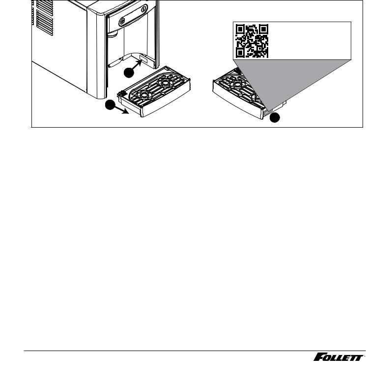
After uncrating and removing all packing material, inspect the equipment for concealed shipping damage.. If damage is found, immediately notify the shipper and contact Follett Corporation so that we can help in the filing of a claim, if necessary.. If needed, the serial number of your dispenser can be found by removing the drip tray and locating the serial number label .. A QR Code is located on the right hand side of the drip tray .. This code allows you to access manuals, technical bulletins, and on- line training related to the 7 Series dispensers..
Scan to access technical documentation or visit
www.follettice.com/7seriesdocs
00981100R00
2
1
3
Check your paperwork to verify that you received the correct dispenser.. Follett configuration numbers are designed to provide information about the type of dispenser you are receiving.. The following is an explanation of the different model numbers..
|
|
7 |
|
UC |
|
100 |
|
|
A |
|
|
|
|
||||
|
|
|
|
|
|
|
|
|
|
|
|
|
|
|
|
|
|
|
|
|
|
|
|
|
|
|
|
|
|
|
|
|
|
|
|
|
|
|
|
|
|
|
|
|
|
|
|
|
|
|
|
|
|
|
|
|
|
|
|
|
|
|
|
|
|
|
|
|
|
|
|
Dispenser Storage |
|
|
Configuration |
|
Ice machine Capacity |
|
Condenser |
||||||||||
Capacity |
|
|
|
|
|||||||||||||
|
|
|
|
|
|
|
|
|
|
|
|
|
|
|
|
||
|
|
|
|
|
|
|
|||||||||||
7 lb |
UC |
Undercounter |
100 |
lb per day |
A |
Air-cooled |
|||||||||||
|
|
UD |
Undercounter - ADA |
|
|
|
|
|
|
|
|
|
|
||||
|
|
|
|
|
|
|
|
|
|
|
|
|
|
|
|
|
|
Important Safety Information––––––––––––––––––––––––––––––––––––––––––
Please read and adhere to the following safety information while installing, using, or servicing your Follett 7 Series Ice Dispenser..
1.Always disconnect power before servicing the dispenser..
2.Ice is slippery.. Maintain counters and floors around dispenser in a clean and ice-free condition..
3.Ice is food.. Follow the recommended cleaning and sanitizing instructions to maintain cleanliness of delivered ice..
4 Undercounter Dispenser and Ice machine 7UC100A/7UD100A

Specifications– –––––––––––––––––––––––––––––––––––––––––––––––––––––
Dimensions
|
7UC100A |
7UD100A |
|
|
|
Width |
14..55" (370 mm) |
14..55" (370 mm) |
|
|
|
Depth |
22..05" (560 mm) |
22..05" (560 mm) |
|
|
|
Height |
33..50" (851 mm) |
31..50" (800 mm) |
|
|
|
Unit Shipping Weight |
110 lb (50 kg) |
110 lb (50 kg) |
|
|
|
Ambient Information
 CAUTION!
The 7UC100A and 7UD100A are for indoor use only.
|
Maximum* |
|
|
Minimum* |
|
|
|
|
|
Air Temperature† |
100 F (38 C) |
|
50 |
F (10 C) |
Water Temperature |
90 F (32..2 C) |
|
40 |
F (4..5 C) |
|
|
|
|
|
Water Pressure |
70 psi |
|
10 psi |
|
|
|
|
|
|
Relative Humidity |
|
55% at 78 F (25..5 C) |
||
|
|
|
|
|
* Use outside of these limitations is misuse and will void warranty..
† Best performance is achieved between 80 F (27 C) and 50 F (10 C)..
Plumbing
§§ Water Inlet: 1/4" MPT
§§ Optional Drain Accessory Kit (item# 00956375 or 00981977): 1/2" ID tubing §§ Water shut-off recommended within 5 ft.. (1..5 m) of dispenser
Water


 WARNING!
Connect to potable water supply only.
§§ Water Mineral Content:
––TDS: greater than 5 ppm (mg/l) but less than 400 ppm (mg/l)
––Hardness: Less than 200 mg/l (12 gpg)
§§ Not recommended for use with softened water
Clearances
§§ 3" (77 mm) behind dispenser for electrical and optional drain connection.. §§ 6" (153 mm) in front of dispenser for ventilation..
Electrical
§§ 115V, 60 Hz, 1 phase, 5A, maximum fuse 15A
§§ Connect to dedicated 15A circuit, fuse or breaker
§§ Must be grounded - requires 3-prong outlet.. Do not remove ground..
Refrigeration


 WARNING!
Do not damage the refrigerant circuit. Refrigerant can cause personal injury and/or damage dispenser.
§§ Refrigerant R134a – 204 grams (7..2 oz..)
Heat Rejection
§§ 1700 BTU/hr (498 W)
Undercounter Dispenser and Ice machine 7UC100A/7UD100A |
5 |

Specifications (continued)– ––––––––––––––––––––––––––––––––––––––––––––––
Detailed Drawing |
|
14.55" (370 mm) |
22.05" (560 mm) |
|
A |
|
|
4.00" |
|
|
|
|
|
|
(102 mm) |
|
|
|
|
FRONT VIEW |
|
|
|
3.81" |
SIDE VIEW |
|
|
|
|
|
(97 mm) |
|
|
Dimension |
7UC100A |
7UD100A (ADA) |
|
|
14.55" (370 mm) |
|
|
|
|
|
|||
A |
33.50” (851 mm) |
31.50” (800 mm) |
|
|
|
|
B |
22.76” (578 mm) |
20.76” (527mm) |
|
|
|
|
C |
22.69” (576 mm) |
20.69” (526 mm) |
|
|
|
|
|
|
2.40" |
|
|
2.98" |
|
|
|
(61 mm) |
|
|
(76 mm) |
|
|
|
power cord |
|
|
1/4" MPT |
|
|
|
|
|
|
water inlet |
A |
|
|
L2 |
|
|
|
|
|
|
G |
|
|
|
|
|
|
L1 |
|
|
|
|
|
|
NEMA 5-15 |
B |
|
|
C |
|
|
|
|
|
|
|
|
|
right angle |
|
|
|
|
BACK VIEW
6 Undercounter Dispenser and Ice machine 7UC100A/7UD100A
Installation–––––––––––––––––––––––––––––––––––––––––––––––––––––––––
 CAUTION!
No service or maintenance should be performed until the technician has thoroughly read this service manual. Except for routine cleaning and sanitizing, only qualified technicians should attempt to service or maintain this equipment.
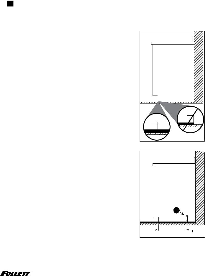
1.Measure to verify that the dispenser will fit in the desired location.. A clearance of at least 3" (77 mm) is required behind the dispenser for the electrical and optional drain connection..
2.Ensure that the finished floor inside the cabinet is flush (level) with the floor outside the cabinet (Fig.. 1).. If the cabinet floor is lower than the finished floor, the cabinet floor must be built up (using appropriate materials) until it is flush with the finished floor.. A flush floor is required for proper operation and maintenance/service of the dispenser..
3.Rough-in the electrical service, water line, and optional Drip Tray Drain Kit*..
Note: The dispenser must be installed such that it can be moved forward at least 4" (10..16 cm) to allow access to the Bin Lid Cleaning Spout (Fig.. 9..6) for dispenser cleaning and sanitizing.. Take this requirement into consideration during rough-in..
§§ Electrical: 115V, single phase, 15A receptacle required.. The dispenser has an integral 8 ft.. (2..4 m) cord and plug..
§§ Water: supply line (with shut-off valve) connects to the dispenser's 1/4" MPT inlet..
*The optional Drip Tray Drain Kit (item# 00956375) requires a floor drain within 15 ft.. (4..5 m) of the dispenser.. For detailed installation instructions, please refer to the instructions shipped with the Drip Tray Drain Kit..
4.Install the angle bracket inside the cabinet,18..15" (461 mm) from the toe kick (Fig.. 2..1).. The bracket prevents the dispenser from being located/pushed beyond the recommended cabinet space depth.. Do not attach the bracket to the dispenser..
Fig.. 1
cabinet space |
floor |
Fig.. 2
1 |
18.15” (461 mm) |
Undercounter Dispenser and Ice machine 7UC100A/7UD100A |
7 |
Installation (continued) –––––––––––––––––––––––––––––––––––––––––––––––––
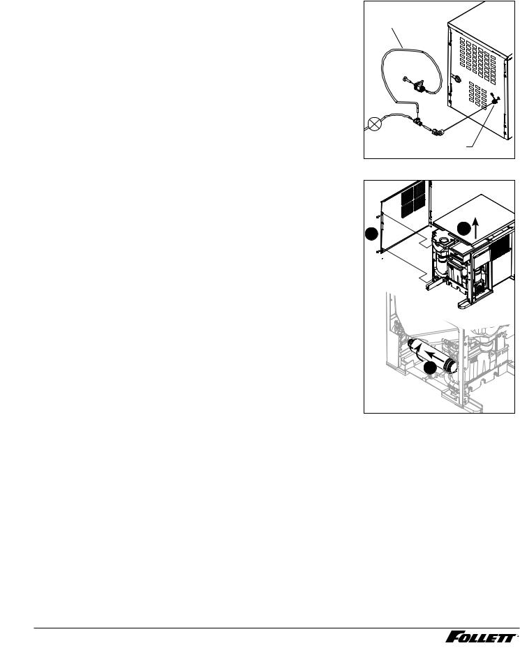
5.Connect water line.. Recommended routing (Fig.. 3) allows easy access to water for cleaning and sanitizing procedure..
Fig.. 3
3' (91.4 cm) |
Plug |
Valve |
1/4" MPT |
6. |
If installing the optional internal water filter*, please complete the |
Fig.. 4 |
|
|
steps shown in Cleaning and Sanitizing on page 11 before |
|
|
|
proceeding.. If not, proceed to step 10.. |
|
|
|
* If your dispenser has the internal water filter option, the water filter must be |
|
|
|
installed for the dispenser to operate.. Because internal components will need to |
|
|
|
be accessed for both procedures, Follett recommends installing the water filter |
2 |
1 |
|
just prior to initial sanitizing.. |
|
|
|
|
|
|
7. |
Lift and remove the top panel, set aside (Fig.. 4..1).. |
|
|
8. |
Remove two screws (Fig.. 4..2) and remove left side panel.. |
|
|
9. |
Install filter as shown.. Turn filter clockwise until it is fully seated |
|
|
|
(Fig.. 4..3).. |
|
|
10. |
Connect power supply.. |
|
|
11. |
Sanitize the dispenser prior to use (see Cleaning and Sanitizing |
|
|
|
on page 11).. |
|
|
|
|
|
3 |
8 Undercounter Dispenser and Ice machine 7UC100A/7UD100A
Maintenance/Cleaning Mode– –––––––––––––––––––––––––––––––––––––––––
Cleaning Mode (Dispensing Disabled) - Use when cleaning surface
Entering Cleaning Mode disables the User Interface and allows you to clean the outside of the dispenser without accidentally dispensing water or ice..
1.To enter Cleaning Mode, press and immediately release the maintenance/clean switch (Fig.. 5..1) so that only "FRESH FILTERED ICE AND WATER" displays in the user interface
(Fig.. 5..2)..
2.To exit Cleaning Mode, press and immediately release the maintenance/clean switch so that the ice and water icons also display in the user interface..
Maintenance Mode (All Operation Disabled) - Use when cleaning ice machine
Entering Maintenance Mode disables all operations and allows you to safely clean and/or sanitize the ice machine and dispenser..
1.To enter Maintenance Mode, press and hold the maintenance/clean switch (Fig.. 5..3) until  displays in the user interface (Fig.. 5..4)..
2.To exit Maintenance Mode, press and hold the maintenance/clean switch until  no longer displays in the user interface..
Note: Entering and exiting Maintenance Mode will reset the six-month periodic maintenance reminder..
Fig.. 5 |
2 |
1 |
4 |
3 |
Accessing Internal Components–––––––––––––––––––––––––––––––––––––––
|
CAUTION! |
Fig.. 6 |
|
|
|
|
|
|
Except for routine cleaning and sanitizing, only qualified |
|
|
|
technicians should attempt to service or maintain this equipment. |
|
|
1. |
Press and hold the maintenance/clean switch (Fig.. 5..1) until |
|
|
|
displays in the user interface (Fig.. 5..2).. |
|
|
2. |
Remove (unscrew) chrome ice dispenser chute (Fig.. 6..1).. |
1 |
|
3. |
Remove the drip tray (Fig.. 6..2).. |
|
|
4. |
Remove the two screws (Fig.. 6..3) on the front panel (behind the |
3 |
|
|
drip tray).. |
|
|
5. |
Remove and set aside the front panel (Fig.. 6..4) - do not |
2 |
|
|
disengage the plug on the back of the User Interface or the |
|
|
|
|
|
|
|
tubing at the water dispenser chute (if so equipped).. |
|
|
|
|
4 |
|
|
Undercounter Dispenser and Ice machine 7UC100A/7UD100A |
9 |
|
Filter Display Indicator Activation––––––––––––––––––––––––––––––––––––––
If you purchased your dispenser with a Follett filter, the filter display indicator activation has been preset at the factory..
If you are using an “after market filter,” an adjustment may be made to activate the “Fresh Filtered Ice & Water” display..
Activating “Fresh Filtered Ice & Water”
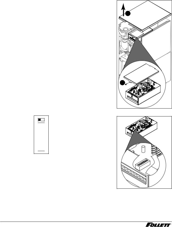
1.Remove the front panel as explained in Accessing Internal Components on page 9 then refer to Fig.. 7..
2.Remove top panel (Fig.. 7..1)..
3.Remove (1) screw and top of control board enclosure (Fig.. 7..2)..
4.Locate the DIP switches on the dispenser's control board (Fig.. 8).. Use a fine-pointed object to move the “Filter” DIP switch (DIP switch #3) to the ON position..
Deactivating the Six-Month Maintenance/Filter Change Reminder
1.Use a fine-pointed object to move the “PM” DIP switch (DIP switch #8) to the ON position..
Fig.. 7
1 |
2 |
OFF ON |
Fig.. 8 |
|
Not used (OFF position) Ice only No internal filter
Not used (OFF position) Not used (OFF position)
15 minute delay Not used (OFF position) Six-month PM enabled
8 7 6 5 4 3 2 1


Ice & water
Internal filter supplied or to display "Fresh Filtered"
30 minute delay
Six-month PM disabled
10 Undercounter Dispenser and Ice machine 7UC100A/7UD100A
Cleaning and Sanitizing––––––––––––––––––––––––––––––––––––––––––––––
Cleaning and sanitizing should be performed at least every 6 months (more often if local water conditions dictate).. For initial startup, only sanitizing is required..
IMPORTANT! Prior to cleaning and sanitizing, the dispenser must be moved forward at least 4" (10..16 cm).. Do not remove the Bin Lid, cleaning and sanitizing solution is added through the Bin Lid Access Spout (Fig.. 9..6)..
 WARNING!
§§ Place the dispenser in Maintenance Mode prior to servicing or cleaning the ice machine. See Maintenance/Cleaning Mode on page 9.
§§ For protection, rubber gloves and safety goggles (and/or face shield) should be worn when handling cleaner/sanitizer.
§§ Do not use bleach, it will damage the dispenser.
Required Supplies
§§ 21 oz.. (0..621 L) or 3 packets Urnex brand cleaner/sanitizer §§ Nu-Calgon IMS-II sanitizing concentrate
§§ Funnel and Bucket
Cleaning and Sanitizing: Ice machine and Dispenser
1.Dispense all the ice out of the unit..
2.Press and hold maintenance/clean switch until  displays in the user interface to enter Maintenance Mode..
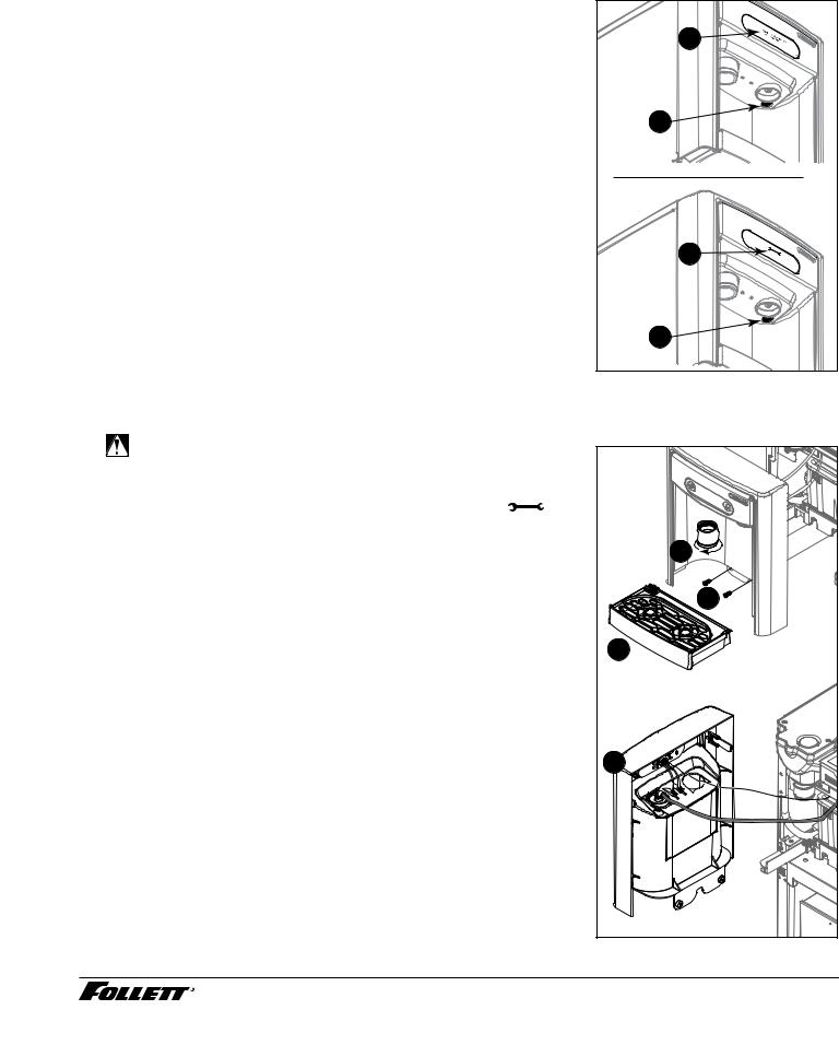
3.Remove (unscrew) chrome ice dispense chute (Fig.. 9..1)..
4.Remove drip tray (Fig.. 9..2)..
5.Remove (2) screws located behind the drip tray (Fig.. 9..3)..
6.Move front panel and place on top or beside unit (Fig.. 9..4)..
7.Remove plug cap from the end of drain tube (Fig.. 9..5) and lower tube to drain water into bucket..
Fig.. 9 |
1 |
3 |
2 |
4 |
6 |
7 |
5 |
8.After the system has been drained of water replace plug cap in drain tube.. Secure tube in holder..
9.Remove cap from bin lid cover (Fig.. 9..6)..
10.Screw bin lid cover cap onto ice discharge chute (Fig.. 9..7)..
11.Mix 21 oz.. (0..621 L) or 3 packets Urnex brand cleaner/sanitizer with three gallons (11..4 L) of water..
12.Pour cleaning solution into bin lid access spout until solution reaches the spout neck..
13.Allow the solution to remain in unit for 15 minutes..
14.While machine is cleaning, remove top and right side panel to access and clean air-cooled condenser..
15.Submerge ice dispense chute in the remainder of solution for 2 minutes.. Rinse with clean, potable water..
16.Drain system by lowering drain tube into bucket..
17.Secure drain tube into holder..
18.Fill one time with potable water and drain with tube.. Secure drain tube..
19.Place a bucket under the dispense chute and remove cap.. Note: Some sanitizing solution will remain and drain out when cap is removed.. Reposition cap on bin lid spout..
20.Reinstall front panel, ice dispense chute, and drip tray..
21.Press and hold maintenance/clean switch to exit Maintenance Mode..
Urnex is a registered trademark of Urnex Brands, Inc..
Undercounter Dispenser and Ice machine 7UC100A/7UD100A |
11 |
Loading...