


Symphony Plus™ 25 and 50 Series Ice and Water Dispensers
25CI425A/W, 25HI425A, 50CI425A/W, 50HI425A
Installation, Operation and Service Manual
|
|
|
25/50CI425A/W-SI Countertop |
|
25/50CI425A/W-LI Countertop Ice-only |
|
|
25/50HI425A-SI Wall Mount |
|
||||||||||||||||||||||||||||||||||||||||||||||
|
|
|
Ice-only Dispenser with |
|
|
|
|
Dispenser with Lever Dispensing |
|
|
Ice-only Dispenser with |
|
|||||||||||||||||||||||||||||||||||||||||||
|
|
|
SensorSAFE™ Dispensing |
|
|
|
|
|
|
|
|
|
|
|
|
|
|
|
|
|
|
|
|
|
|
|
|
|
SensorSAFE Dispensing |
|
|||||||||||||||||||||||||
|
|
|
|
|
|
|
|
|
|
|
|
|
|
|
|
|
|
|
|
|
|
|
|
|
|
|
|
|
|
|
|
|
|
|
|
|
|
|
|
|
|
|
|
|
|
|
|
|
|
|
|
|
|
|
|
|
|
|
|
|
|
|
|
|
|
|
|
|
|
|
|
|
|
|
|
|
|
|
|
|
|
|
|
|
|
|
|
|
|
|
|
|
|
|
|
|
|
|
|
|
|
|
|
|
|
|
|
|
|
|
|
|
|
|
|
|
|
|
|
|
|
|
|
|
|
|
|
|
|
|
|
|
|
|
|
|
|
|
|
|
|
|
|
|
|
|
|
|
|
|
|
|
|
|
|
|
|
|
|
|
|
|
|
|
|
|
|
|
|
|
|
|
|
|
|
|
|
|
|
|
|
|
|
|
|
|
|
|
|
|
|
|
|
|
|
|
|
|
|
|
|
|
|
|
|
|
|
|
|
|
|
|
|
|
|
|
|
|
|
|
|
|
|
|
|
|
|
|
|
|
|
|
|
|
|
|
|
|
|
|
|
|
|
|
|
|
|
|
|
|
|
|
|
|
|
|
|
|
|
|
|
|
|
|
|
|
|
|
|
|
|
|
|
|
|
|
|
|
|
|
|
|
|
|
|
|
|
|
|
|
|
|
|
|
|
|
|
|
|
|
|
|
|
|
|
|
|
|
|
|
|
|
|
|
|
|
|
|
|
|
|
|
|
|
|
|
|
|
|
|
|
|
|
|
|
|
|
|
|
|
|
|
|
|
|
|
|
|
|
|
|
|
|
|
|
|
|
|
|
|
|
|
|
|
|
|
|
|
|
|
|
|
|
|
|
|
|
|
|
|
|
|
|
|
|
|
|
|
|
|
|
|
|
|
|
|
|
|
|
|
|
|
|
|
|
|
|
|
|
|
|
|
|
|
|
|
|
|
|
|
|
|
|
|
|
|
|
|
|
|
|
|
|
|
|
|
|
|
|
|
|
|
|
|
|
|
|
|
|
|
|
|
|
|
|
|
|
|
|
|
|
|
|
|
|
|
|
|
|
|
|
|
|
|
|
|
|
|
|
|
|
|
|
|
|
|
|
|
|
|
|
|
|
|
|
|
|
|
|
|
|
|
|
|
|
|
|
|
|
|
|
|
|
|
|
|
|
|
|
|
|
|
|
|
|
|
|
|
|
|
|
|
|
|
|
|
|
|
|
|
|
|
|
|
|
|
|
|
|
|
|
|
|
|
|
|
|
|
|
|
|
|
|
|
|
|
|
|
|
|
|
|
|
|
|
|
|
|
|
|
|
|
|
|
|
|
|
|
|
|
|
|
|
|
|
|
|
|
|
|
|
|
|
|
|
|
|
|
|
|
|
|
|
|
|
|
|
|
|
|
|
|
|
|
|
|
|
|
|
|
|
|
|
|
|
|
|
|
|
|
|
|
|
|
|
|
|
|
|
|
|
|
|
|
|
|
|
|
|
|
|
|
|
|
|
|
|
|
|
|
|
|
|
|
|
|
|
|
|
|
|
|
|
|
|
|
|
|
|
|
|
|
|
|
|
|
|
|
|
|
|
|
|
|
|
|
|
|
|
|
|
|
|
|
|
|
|
|
|
|
|
|
|
|
|
|
|
|
|
|
|
|
|
|
|
|
|
|
|
|
|
|
|
|
|
|
|
|
|
|
|
|
|
|
|
|
|
|
|
|
|
|
|
|
|
|
|
|
|
|
|
|
|
|
|
|
|
|
|
|
|
|
|
|
|
|
|
|
|
|
|
|
|
|
|
|
|
|
|
|
|
|
|
|
|
|
|
|
|
|
|
|
|
|
|
|
|
|
|
|
|
|
|
|
|
|
|
|
|
|
|
|
|
|
|
|
|
|
|
|
|
|
|
|
|
|
|
|
|
|
|
|
|
|
|
|
|
|
|
|
|
|
|
|
|
|
|
|
|
|
|
|
|
|
|
|
|
|
|
|
|
|
|
|
|
|
|
|
|
|
|
|
|
|
|
|
|
|
|
|
|
|
|
|
|
|
|
|
|
|
|
|
|
|
|
|
|
|
|
|
|
|
|
|
|
|
|
|
|
|
|
|
|
|
|
|
|
|
|
|
|
|
|
|
|
|
|
|
|
|
|
|
|
|
|
|
|
|
|
|
|
|
|
|
|
|
|
|
|
|
|
|
|
|
|
|
|
|
|
|
|
|
|
|
|
|
|
|
|
|
|
|
|
|
|
|
|
|
|
|
|
|
|
|
|
|
|
|
|
|
|
|
|
|
|
|
|
|
|
|
|
|
|
|
|
|
|
|
|
|
|
|
|
|
|
|
|
|
|
|
|
|
|
|
|
|
|
|
|
|
|
|
|
|
|
|
|
|
|
|
|
|
|
25/50CI425A/W-S Countertop Dispenser |
25/50CI425A/W-L Countertop Dispenser |
25/50HI425A-S Wall Mount Dispenser |
with SensorSAFE™ Dispensing |
with Lever Dispensing |
with SensorSAFE Dispensing |
Following installation, please forward this manual to the appropriate operations person.
801 Church Lane • Easton, PA 18040, USA
Toll free (877) 612-5086 • +1 (610) 252-7301 www.follettice.com
Order parts online: www.follettice.com 01033679R03
Contents
Welcome to Follett. . . . . . . . . . . . . . . . . . . . . . . . . . . . . . . . . . . . . . . . . . . . . . . . . . . . . . . . . . . . . . . . . . . . . . . . . . |
. 3 |
Before you begin. . . . . . . . . . . . . . . . . . . . . . . . . . . . . . . . . . . . . . . . . . . . . . . . . . . . . . . . . . . . . . . . . . . . . . . . . . |
3 |
Specifications. . . . . . . . . . . . . . . . . . . . . . . . . . . . . . . . . . . . . . . . 4 |
|
Electrical.. . . . . . . . . . . . . . . . . . . . . . . . . . . . . . . . . . . . . . . . . . . . . . . . . . . . . . . . . . . . . . . . . . . . . . . . . . . . . . . . |
5 |
Ambient. . . . . . . . . . . . . . . . . . . . . . . . . . . . . . . . . . . . . . . . . . . . . . . . . . . . . . . . . . . . . . . . . . . . . . . . . . . . . . . . . |
5 |
Plumbing. . . . . . . . . . . . . . . . . . . . . . . . . . . . . . . . . . . . . . . . . . . . . . . . . . . . . . . . . . . . . . . . . . . . . . . . . . . . . . . . |
5 |
Ventilation clearances. . . . . . . . . . . . . . . . . . . . . . . . . . . . . . . . . . . . . . . . . . . . . . . . . . . . . . . . . . . . . . . . . . . . . . |
5 |
Uncrated weight. . . . . . . . . . . . . . . . . . . . . . . . . . . . . . . . . . . . . . . . . . . . . . . . . . . . . . . . . . . . . . . . . . . . . . . . . . . |
5 |
Installation. . . . . . . . . . . . . . . . . . . . . . . . . . . . . . . . . . . . . . . . . |
6 |
Before you begin. . . . . . . . . . . . . . . . . . . . . . . . . . . . . . . . . . . . . . . . . . . . . . . . . . . . . . . . . . . . . . . . . . . . . . . . . . |
6 |
Installing countertop dispensers with rear exiting utilities (no legs). . . . . . . . . . . . . . . . . . . . . . . . . . . . . . . . . . . |
6 |
Installing countertop dispensers with bottom exiting utilities. . . . . . . . . . . . . . . . . . . . . . . . . . . . . . . . . . . . . . . . . |
7 |
Installing wall mount dispensers. . . . . . . . . . . . . . . . . . . . . . . . . . . . . . . . . . . . . . . . . . . . . . . . . . . . . . . . . . . . . . |
8 |
User information. . . . . . . . . . . . . . . . . . . . . . . . . . . . . . . . . . . . . . |
11 |
How the dispenser works.. . . . . . . . . . . . . . . . . . . . . . . . . . . . . . . . . . . . . . . . . . . . . . . . . . . . . . . . . . . . . . . . . . . |
11 |
Cleaning/descaling and sanitizing . . . . . . . . . . . . . . . . . . . . . . . . . . . . . . . 11
Weekly . . . . . . . . . . . . . . . . . . . . . . . |
. . . . . . . . . . . . . . . . . . . . . . . . . . . . . . . . . . . . . . . . . . . . . . . . . . . . . . . . . . |
12 |
Monthly.. . . . . . . . . . . . . . . . . . . . . . . . . |
. . . . . . . . . . . . . . . . . . . . . . . . . . . . . . . . . . . . . . . . . . . . . . . . . . . . . . . |
12 |
Semi-Annually (more often if conditions dictate) . . . . . . . . . . . . . . . . . . . . . . . . . . . . . . . . . . . . . . . . . . . . . . . . . |
12 |
|
Service. . . . . . . . . . . . . . . . . . . . . . . . . . . . . . . . . . . . . . . . . . |
15 |
|
Ice machine Operation (all models). |
. . . . . . . . . . . . . . . . . . . . . . . . . . . . . . . . . . . . . . . . . . . . . . . . . . . . . . . . . . |
15 |
The icemaking process.................................................................... |
|
15 |
Water system . . . . . . . . . . . . . . . . . . |
. . . . . . . . . . . . . . . . . . . . . . . . . . . . . . . . . . . . . . . . . . . . . . . . . . . . . . . . . . |
16 |
Wiring diagram. . . . . . . . . . . . . . . . . |
. . . . . . . . . . . . . . . . . . . . . . . . . . . . . . . . . . . . . . . . . . . . . . . . . . . . . . . . . . |
18 |
Ice machine operational and diagnostic sequences . . . . . . . . . . . . . . . . . . . . . . . . . . . . . . . . . . . . . . . . . . . . . . |
20 |
|
Diagnostic Stages. . . . . . . . . . . . . . . . . . . . . . . . . . |
. . . . . . . . . . . . . . . . . . . . . . . . . . . . . . . . . . . . . . . . . . . . . . |
25 |
Refrigeration system. . . . . . . . . . . . . . . . . . . |
. . . . . . . . . . . . . . . . . . . . . . . . . . . . . . . . . . . . . . . . . . . . . . . . . . . |
30 |
Dispenser troubleshooting . . . . . . . . . . . . . . . . . . . . . . . . . . . . . . . . . |
. 32 |
|
Lever model troubleshooting guide . |
. . . . . . . . . . . . . . . . . . . . . . . . . . . . . . . . . . . . . . . . . . . . . . . . . . . . . . . . . . |
32 |
SensorSAFE model troubleshooting guide . . . . . . . . . . . . . . . . . . . . . . . . . . . . . . . . . . . . . . . . . . . . . . . . . . . . . |
32 |
|
Ice machine removal instructions. . |
. . . . . . . . . . . . . . . . . . . . . . . . . . . . . |
33 |
Evaporator disassembly. . . . . . . . . . |
. . . . . . . . . . . . . . . . . . . . . . . . . . . . . . . . . . . . . . . . . . . . . . . . . . . . . . . . . . |
37 |
Evaporator reassembly. . . . . . . . . . . . . . . |
. . . . . . . . . . . . . . . . . . . . . . . . . . . . . . . . . . . . . . . . . . . . . . . . . . . . . |
38 |
Gearmotor replacement. . . . . . . . . . |
. . . . . . . . . . . . . . . . . . . . . . . . . . . . . . . . . . . . . . . . . . . . . . . . . . . . . . . . . . |
38 |
Replacement parts. . . . . . . . . . . . . . . . . . . . . . . . . . . . . . . . . . . . . |
39 |
|
Dispenser exterior. . . . . . . . . . . . . . . . . . . . . . . . . . . . |
. . . . . . . . . . . . . . . . . . . . . . . . . . . . . . . . . . . . . . . . . . . . |
39 |
Wheel motor and drive system. . . . . . |
. . . . . . . . . . . . . . . . . . . . . . . . . . . . . . . . . . . . . . . . . . . . . . . . . . . . . . . . |
40 |
Dispense chute and splash panel (models with SensorSAFE infrared dispensing). . . . . . . . . . . . . . . . . . . . . |
. 41 |
|
Dispense chute and splash panel (models with lever dispensing) . . . . . . . . . . . . . . . . . . . . . . . . . . . . . . . . . . . |
42 |
|
Dispenser electrical box – SensorSAFE models.. . . . . . . . . . . . . . . . . . . . . . . . . . . . . . . . . . . . . . . . . . . . . . . . |
43 |
|
Dispenser electrical box – lever models. . . . . . . . . . . . . . . . . . . . . . . . . . . . . . . . . . . . . . . . . . . . . . . . . . . . . . . |
44 |
|
Water and drain . . . . . . . . . . . . . . . . |
. . . . . . . . . . . . . . . . . . . . . . . . . . . . . . . . . . . . . . . . . . . . . . . . . . . . . . . . . . |
45 |
Water treatment accessories for Symphony Plus ice and water dispensers. . . . . . . . . . . . . . . . . . . . . . . . . . . |
46 |
|
Air-cooled ice machines. . . . . . . . . . |
. . . . . . . . . . . . . . . . . . . . . . . . . . . . . . . . . . . . . . . . . . . . . . . . . . . . . . . . . . |
47 |
Water-cooled ice machines.. .. .. .. .. .. .. .. .. .. .. .. .. .. .. .. .. .. .. .. .. .. .. .. .. .. .. .. .. .. .. .. .. .. .. .. .. .. .. .. .. .. .. .. .. .. .. .. .. .. .. .. .. .. .. .. .. .. .. .. .. .. .. .. .. |
49 |
|
Evaporator replacement parts . . . . . |
. . . . . . . . . . . . . . . . . . . . . . . . . . . . . . . . . . . . . . . . . . . . . . . . . . . . . . . . . . |
51 |
Ice machine electrical components. |
. . . . . . . . . . . . . . . . . . . . . . . . . . . . . . . . . . . . . . . . . . . . . . . . . . . . . . . . . . |
. . |
2 |
25CI425A/W, 25HI425A, 50CI425A/W, 50HI425A |

Welcome to Follett
Follett equipment enjoys a well-deserved reputation for excellent performance, long-term reliability and outstanding after-the-sale support.. To ensure that this equipment delivers that same degree of service, we ask that you take
a moment to review the installation portion of this manual before beginning to install the unit.. Our installation instructions are designed to help you achieve a trouble-free installation.. Should you have any questions or require technical help at any point, please call our technical service group at (877) 612-5086 or
(610) 252-7301..
Note: To expedite assistance, all correspondence or communication MUST include the model number, serial number and complete and detailed explanation of the problem..
Before you begin
After uncrating and removing all packing material, inspect the equipment for concealed shipping damage.. If damage is found, notify the shipper immediately and contact Follett Corporation so that we can help in the filing
of a claim, if necessary..
Check your paperwork to determine which model you have.. Follett model numbers are designed to provide information about the type and capacity of Follett ice dispensing equipment.. Following is an explanation of the different model numbers..
25CI425A-LI
 I = ice-only; no water
Dispense actuation, L = lever, S = SensorSAFE
Condenser type, A = air-cooled, water-cooled
Ice machine capacity in lbs per day
Ice machine location, I = integral
Dispenser configuration, C = countertop, H = wall mount
Approximate storage capacity in lbs


 CAUTION!
§§ Do not tilt any unit further than 30° off vertical during uncrating or installation..
§§ Dispenser bin area contains mechanical, moving parts.. Keep hands and arms clear of this area at all times.. If access to this area is required, power to unit must be disconnected first..
§§ Follett recommends a Follett water filter system be installed in the ice machine inlet water line (standard capacity #00130299, high capacity #00978957, carbonless high capacity #01050442)..
§§ Prior to operation clean and sanitize the dispenser in accordance with instructions found in this manual.. §§ Ice is slippery.. Be sure counters and floors around dispenser are clean, dry and free of ice..
§§ Do not block right side air intake or top air exhaust..
25CI425A/W, 25HI425A, 50CI425A/W, 50HI425A |
3 |

Specifications
Countertop
Front View |
Right Side View |
21" (53.4 cm) |
|
|
24" (61 cm) |
25CI400A/W |
|
|
|
36" |
|
|
|
(91.5 cm) |
|
|
|
50CI400A/W |
|
|
|
40" |
|
|
|
(101.6 cm) |
EXHAUSTAIR |
|
|
INTAKEAIR |
14.25" |
10.5" |
|
|
|
(26.7 cm) |
|
|
|
(36.2 cm) |
|
|
|
|
23" |
|
|
|
(58.5 cm) |
Wall mount
Front View |
Right Side View |
21.5" (54.6 cm) |
24.5" (62.2 cm)* |
25HI400A/W |
|
|
36.5" |
|
|
(92.7 cm) |
|
|
50HI400A/W |
|
|
40.5" |
|
|
(102.9 cm) |
EXHAUSTAIR |
|
INTAKEAIR |
14.25" |
|
|
|
(36.2 cm) |
|
|
|
17" |
|
|
|
|
|
|
* Includes .5” (13 mm) for bracket supplied with unit. |
|
(43.2 cm) |
||
Rear View
3/8" FPT |
|
condenser |
|
inlet (water- |
|
cooled only) |
|
3/8" FPT |
|
condenser |
|
outlet (water- |
|
cooled only) |
|
3/4" FPT |
|
drain |
|
NEMA |
3/8" water |
5-15 |
|
|
inlet |
|
2.63" (6.6 cm) |
0.88 (23 mm) |
1.38" (3.5 cm) |
DRAIN |
2.56" (6.5 cm) |
3/4 MPT MALE |
5.69" (14.4 cm) |
|
7.69" (19.5 cm) |
|
10.5" |
|
(26.7 cm) |
Rear View
NEMA 


 5-15
5-15 


21.5" (54.6 cm) |
4 |
25CI425A/W, 25HI425A, 50CI425A/W, 50HI425A |
Electrical
§§ 115 V, 60 Hz, 1 phase, 11..0A
§§ Connect to a 15A dedicated circuit..
§§ Furnished with 7 ft (2 m) power cord with a 90° NEMA hospital grade 5-15 plug..
Ambient
Air temp* |
100 F/38 C Max.. |
50 |
F/10 C Min.. (Best performance below 80 F (27 C) |
|
|
|
|
|
|
Water temp† |
90 |
F/32 C Max.. |
45 |
F/7 C Min.. (Best performance below 70 F (21 C) |
Water pressure |
70 |
P..S..I../5Bar Max.. |
10 P..S..I../0..7 Bar Min.. |
|
* Ambient air temperature is measured at the air-cooled condenser coil inlet.. |
||||
† Ambient water temperature is measured in the ice machine float reservoir.. |
||||
Plumbing
|
Connections 25/50CI425A |
Rough-ins 25/50HI425A |
|
|
|
Dispenser drain |
3/4" MPT |
Air-cooled 3/4" FPT |
|
|
|
Water inlet |
3/8" FPT |
3/8" FPT |
|
|
|
Condenser inlet |
Water-cooled 3/8" FPT |
N/A |
Condenser outlet |
Water-cooled 3/8" FPT |
N/A |
|
|
|
Note: Water shut-off recommended within 10 ft.. (3m) of dispenser.. Drain to be hard-piped and insulated.. Maintain at least 1/4" per foot (20mm per 1m) run of slope..
Ventilation clearances
|
Air-cooled |
Water-cooled |
Required for ventilation |
3" (77 mm) each side |
N/A |
|
|
|
Suggested for service |
12" (30..5 cm) top, |
12" (30..5 cm) top |
|
6" (15..3 cm ) left side |
|
|
|
|
Note: Do not block right side air intake or right side air exhaust..
Uncrated weight
§§ 25/50 CI425A/W (countertop): 215 lbs.. (98 kg) §§ 25/50 HI425A/W (wall mount): 230 lbs.. (105 kg)
25CI425A/W, 25HI425A, 50CI425A/W, 50HI425A |
5 |
Installation
Before you begin
§§ All dispensers must be installed level in both directions to ensure proper operation.. §§ Provide ventilation clearances mentioned above..
§§ Countertop units provide the option of taking utilities out bottom or back of dispenser (on wall mount units and countertop units with legs, utilities exit from back)..
§§ Wall mount model utilities exit through back of dispenser only.. . §§ Directions for each installation follow..


 WARNING!
§§ DO NOT LIFT UNIT AT THESE POINTS.. Panels will not support weight of unit
§§ Failure to follow warning may result in equipment damage or personal injury
Installing countertop dispensers with rear exiting utilities (no legs)
1.Position dispenser in desired location..
2.Mark dispenser outline on counter and remove dispenser..
3.Drill four 7/16" holes in counter to anchor dispenser to counter (Fig. 1)..
4.Apply a thick bead approximately 1/4" (7 mm) diameter of NSF listed silicone sealant (Dow Corning* RTV-732 or equivalent) 1/4" (7 mm) inside marked outline of dispenser..
5. Reposition dispenser on counter and secure to counter with four 3/8"-16NC bolts..
6.Smooth excess sealant around outside of dispenser..
7.Make utility connections (Fig. 2)..


 CAUTION!
§§ Do not connect water-cooled condenser outlet line to the dispenser drain line..
8.Turn on water supply and check for leaks..
9.Clean and sanitize dispenser and ice machine before putting into service..
10.Turn power on and allow ice machine to produce ice..
*Dow Corning is a register trademark of Dow Corning Corporation in the United States and other countries
Fig. 1 Countertop anchoring locations
1.56" |
|
(40 mm) |
|
|
4X |
12.50" |
Ø.375" |
(31.8 cm) |
(10 mm) |
|
hole |
.50" 
 20" (50.8 cm)
  (13 mm)
Fig. 2 Utility connections as viewed from top for countertop back access
condenser outlet |
|
|
|
3/8" FNPT |
drain |
|
|
condenser inlet |
|
||
3/4" MPT |
power |
||
3/8" FNPT |
|||
|
|
||
potable water |
|
|
|
3/8" FNPT |
|
|
6 |
25CI425A/W, 25HI425A, 50CI425A/W, 50HI425A |

Installing countertop dispensers with bottom exiting utilities


 WARNING!
§§ A sturdy work surface capable of supporting the entire dispenser must be used..
§§ The work surface must be large enough to accommodate height of dispenser..
§§ Failure to provide proper support may result in personal injury..
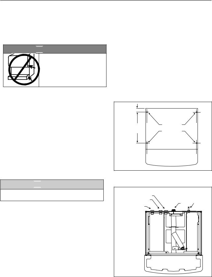
1.Position dispenser with dispense chutes facing upward on sturdy work surface (Fig. 3)..
2.Move drain fitting from back of dispenser and mount (Fig. 4.1)..
3.Cut drain tube to length and attach to barbed connection (Fig. 4.2)..
4.Move inlet water fitting from back of dispenser and mount (Fig. 4.3)..
5.Cut water tubing to length and re-insert into water fitting.
6.Water-cooled only. Disconnect internal condenser water inlet and outlet fittings..
7.Water-cooled only. Relocate water inlet and outlet fittings and reconnect (Fig. 4.4).. Note: The water inlet is connected to the condenser; the outlet line is connected to the water regulating valve..
8.Remove the drain plug from the internal drain line connection point and relocate to back of dispenser and reconnect..
9.Raise the dispenser upright and position in desired location..
10.Mark dispenser outline on counter and remove dispenser..
11.Cut countertop utility opening and drill four 7/16" holes to anchor dispenser to counter
(Fig. 5)..
12.Apply a thick bead approximately 1/4" (7 mm) diameter of NSF-listed silicone sealant (Dow Corning* RTV-732 or equivalent) 1/4" (7 mm) inside marked outline of dispenser..
13.Reposition dispenser on counter and secure to counter with four 3/8"-16NC bolts..
14.Smooth excess sealant around outside of dispenser and make utility connections through countertop cutout..
CAUTION
§§ Do not connect water-cooled condenser outlet line to the dispenser drain line..
15.Turn on water supply and check for leaks..
16.Clean and sanitize dispenser and ice machine..
17.Turn power on and allow ice machine to produce ice..
Fig. 3
 5.00" (12.7 cm)
min.
Fig. 4
2TRIM DRAIN TUBE FOR NEW DRAIN FITTING
LOCATION.
3


 4
4


 1
1 


Water cooled only
5
Fig. 5
|
21.00" |
|
|
|
|
(53.3 cm) |
0.50" |
|
|
4X |
|
20.00" |
(13 mm) |
|
Ø.375" |
1.56" |
(50.8 cm) |
1.56" |
|
(10 mm) |
(4.0 cm) |
|
(4.0 cm) |
|
hole |
|
|
||
|
|
|
|
|
|
|
|
2.50" |
16.50" |
|
|
Cutout |
(6.36 cm) |
(41.9 cm) |
14.00" |
|
|
|
|
connections |
12.50" |
|||
(35.6 cm) |
through |
(31.8 cm) |
||
|
|
bottom |
|
|
16.00" |
|
|
|
7.00" |
(40.7 cm) |
|
|
|
|
|
|
(17.8 cm) |
||
|
|
|
||
25CI425A/W, 25HI425A, 50CI425A/W, 50HI425A |
7 |

Installing wall mount dispensers


 WARNING!
§§ Wall mount dispensers are intended to be mounted above a sink, eliminating the need for a drain pan..
§§ Before beginning installation verify that the sink size and location meet the requirements shown in Fig.. 6..
§§ If requirements are not met, a drain pan must be used to prevent ice and water from falling on counter or floor..
§§ FAILURE TO TAKE THESE PRECAUTIONS COULD RESULT IN SLIPS AND FALLS ON WET FLOORS
Fig. 6 – Minimum sink requirements (without drain pan), front view
|
Sink centered |
|
Sink centered |
|||
|
below chutes |
below dispenser |
||||
|
|
|
|
|
|
|
|
|
|
|
|
|
|
|
|
|
|
|
|
|
|
|
|
|
|
|
|
|
|
|
|
|
|
|
|
|
|
|
|
|
|
|
|
|
|
|
|
|
|
|
|
|
|
|
|
|
|
|
|
|
|
|
|
|
|
|
|
|
|
|
21.50" |
|
|
|
|
|
21.50" |
|
|
|
|
|
|
|
|
||
(54.7 cm) |
|
(54.7 cm) |
||||||
|
|
|
|
|
|
|||
|
|
|
14.25" |
|
|
|
|
|
|
|
23.00" |
|
|
|
||
|
(36.2 cm) min. |
|
|
|
|
|
(58.5 cm) min. |
|
||||||||
|
|
|
|
|
|
|
|
|
|
|
|
|
|
|
|
|
|
|
|
|
|
|
|
|
|
|
|
|
|
|
|
|
|
|
|
|
|
|
|
|
|
|
|
|
|
|
|
|
|
|
|
|
|
|
|
|
|
|
|
|
|
|
|
|
|
|
|
|
Fig. 7 – Minimum sink requirements (without drain |
|
|
pan), side view |
|
|
24.36" (61.9 cm) |
|
|
|
25HI425 |
|
|
35.88" (91.1 cm) |
|
|
50HI425 |
|
|
39.88" (101.3 cm) |
|
17.01" |
|
|
(43.2 cm) |
|
|
18.92" |
|
|
(48.1 cm) |
18.00" (45.7 cm) |
|
30.00" (76.2 cm) |
|
|
MIN DISTANCE TO SINK FRONT |
|
|
|
SUGGESTED POWER |
|
|
CORD ROUTING |
8 |
25CI425A/W, 25HI425A, 50CI425A/W, 50HI425A |
|

1. Locate wall bracket mounting position relative |
Fig. 8 – Wall bracket location guide |
|
|
||
|
to wall studs (Fig. 8).. Install the supplied |
|
|
|
|
|
wall bracket with six 3/8" diameter fasteners |
TOP VIEW |
|
|
|
|
(Fig. 10.1).. |
|
|
WALL STUDS |
|
|
Note: Three holes are available at each fastening |
|
|||
|
|
|
|
||
|
site to allow capture of studs or supports |
1.00" (25 mm) |
|
|
|
|
within the wall.. |
|
|
|
|
|
|
2.00" (51 mm) |
|
|
|
|
|
|
|
|
|
2. |
Locate and cut utility hole (Fig. 10.2) in wall |
FRONT VIEW |
|
|
|
|
using Fig. 9 dimensions.. |
|
|
WALL STUDS |
|
3. |
Rough in utilities.. Wall mount bracket |
ANCHOR POINTS |
|
|
|
|
dimensions can be used as a template.. |
0.438" (11 mm) |
|
|
|
|
§§ Water: 1/2" FNPT |
|
CLEARANCE |
|
|
|
|
|
|
25HI425A |
|
|
§§ Drain: 3/4" MPT |
|
|
|
|
|
|
|
|
13" (33.0 cm) |
|
4. |
Lift dispenser onto wall bracket positioning |
|
|
50HI425A |
|
16.00" |
0.75" |
15" (38.1 cm) |
|||
|
unit so that hook on back of dispenser is |
(406 mm) |
|
||
|
(19 mm) |
||||
|
captured by wall bracket support angle |
|
|
|
|
|
(Fig. 10.3).. |
|
|
|
25HI425A |
5. |
Install two 1/4" X 20 screws through bottom of |
12.37" (31.4 cm) |
|
19" (48.3 cm) |
|
|
wall bracket into bottom of dispenser to secure |
|
50HI425A |
||
|
dispenser to wall bracket (Fig. 10.4).. |
3.44" (8.7 cm) |
|
21" (53.3 cm) |
|
|
|
|
|||
6. Install supplied 1/2" MPT X 3/8" push-in |
|
6.00" |
|||
|
adapter onto 1/2" FNPT water supply.. |
|
|||
|
|
(15.2 cm) |
|||
|
|
|
3.53" (9.0 cm) |
|
|
|
|
|
WALL CUTOUT |
|
|
Fig. 9 – Wall mount, utility location |
|
Fig. 10 – Wall mount bracket and fastener |
|||
|
FRONT VIEW |
requirements |
|
|
|
|
|
|
|
||
|
|
|
3 |
|
|
|
|
|
1 |
|
|
1.43" |
(3.6 mm) |
|
|
|
|
|
3.99" (10.1 cm) |
0.77" (2.0 cm) |
|
|
|
|
|
|
|
|
|
POTABLE WATER |
|
|
|
|
|
3/8 COPPER TUBE |
|
|
|
|
|
|
6.70" (17.0 cm) |
|
2 |
|
|
POWER CORD EXIT |
|
|
|
||
|
10.69" (27.1 cm) |
|
|
|
|
3/4 COPPER TUBE |
|
|
|
|
|
|
|
|
4 |
|
|
25CI425A/W, 25HI425A, 50CI425A/W, 50HI425A |
|
|
9 |
||
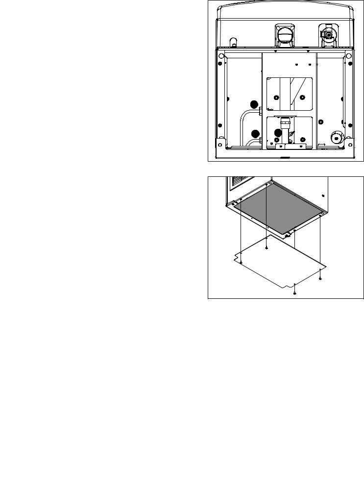
7.Connect supplied 3/8" water line between water supply and water inlet fitting (Fig. 11.1)..
8.Using supplied 3/4" drain tubing and barbed fittings, connect 3/4" barbed drain elbow fitting on dispenser to 3/4" FNPT drain (Fig. 11.2)..
9.Route power cord through utility access hole to power supply (Fig. 11.3)..
10.Turn on water supply and check for leaks..
11. Install bottom panel (Fig. 12)..
Fig. 11 – Dispenser bottom view
1 |
|
3 |
2 |
Fig. 12
10 |
25CI425A/W, 25HI425A, 50CI425A/W, 50HI425A |
User information
How the dispenser works
Follett’s 25/50CI series automatic-load ice and water dispensers are equipped with Follett’s 425 lb (181kg)/day ice machine.. In the continuous icemaking process, water freezes to the inside wall of the evaporator.. A rotating stainless steel auger carries the ice to the top of the evaporator where it is compressed and extruded through an outlet port.. The ice is then pushed through a tube to the storage hopper.. When the hopper is full, a bin thermostat opens and shuts the ice machine off.. When the dispense mechanism is activated, a dispense motor is turned on, causing the wheel to turn.. This moves ice to the dispense chute where it drops by gravity into the container held below the chute..
How SensorSAFE infrared dispensing works
Follett’s SensorSAFE infrared dispensing maximizes sanitation and minimizes the possibility of cross-contamination by eliminating physical contact between the cup or container and dispenser.. Sensors in the panel use reflected infrared light to detect the presence of the container and send a signal to a control board which then activates the appropriate components for ice or water dispensing..
The SensorSAFE infrared dispensing package includes a cleaning switch under the left side of the front cover which temporarily shuts off dispensing to allow cleaning of the panel and lenses.. If the switch is not turned back on after cleaning, the dispenser automatically resets after two minutes for normal operation..
SensorSAFE infrared dispensing also includes a time limit safety feature which automatically stops ice dispensing after one minute of continuous dispensing.. Dispensing can be resumed by moving the container away from the dispenser and returning it to the activation zone..
Cleaning/descaling and sanitizing
Follett ice machines and dispensers, and their associated cleaning and sanitizing procedures, are designed for use with potable water sources.. The presence, or suspected presence, of infectious agents may call for additional measures, including the replacement of components and more comprehensive disinfection measures.. Follett recommends that these cleaning and sanitizing procedures be reviewed with the appropriate infectious agent subject matter experts to assure complete remediation..
Periodic cleaning/descaling and sanitizing of Follett’s ice and water dispenser and ice machine system is required to ensure peak performance and delivery of clean, sanitary ice.. The recommended cleaning procedures that follow should be performed at least as frequently as recommended and more often if environmental conditions dictate..
Follett recommends sanitizing the pressurized water lines prior to cleaning/descaling and sanitizing the ice machine/dispenser.. Follett offers two kits: order P/N 01089572 when a Follett filter system with a pre-filter bowl is present, or P/N 01089580 when a Follett filter system is not present.. Follow the instructions provided with the
respective kits to sanitize the pressurized water lines immediately before cleaning/descaling and sanitizing the ice machine/dispenser..
Cleaning of the condenser can usually be performed by facility personnel.. Cleaning/descaling and sanitizing of the ice machine system should be performed by your facility’s trained maintenance staff or a Follett authorized
service agent.. Regardless of who performs the cleaning, it is the operator’s responsibility to see that this cleaning is performed according to the schedule below.. Service problems resulting from lack of preventive maintenance will not be covered under the Follett warranty..
Recommended cleaning/descaling and sanitizing intervals*
Symphony Plus |
Frequency |
Drain Line |
weekly |
|
|
Drain Pan/Drip Pan |
weekly |
|
|
Exterior, Water Station Tube |
as needed |
|
|
Condenser |
monthly (air-cooled only) |
Dispenser and Components |
semi-annually |
Ice Machine |
semi-annually |
|
|
Transport Tube |
semi-annually |
|
|
Ice Storage Area/Bin |
semi-annually |
|
|
Pressurized Water Sanitizing |
semi-annually |
* Ice machine and dispenser must be sanitized prior to start-up..
25CI425A/W, 25HI425A, 50CI425A/W, 50HI425A |
11 |

Weekly


 CAUTION!
§§ Do not use solvents, abrasive cleaners, metal scrapers or sharp objects to clean any part of the dispenser..
Dispenser drain pan and drain line
1. Pour 1 gal.. (3..8 L) of hot tap water into drain pan to flush drains..
Splash panel front, SensorSAFE infrared dispensing
1.Deactivate dispensing by pressing and releasing clean switch located on left side of unit under top front cover..
2.Clean lens and splash panel front using a soft cloth and mild, non-abrasive, non-chlorine based cleaner..
3.Reactivate dispensing by pressing and releasing clean switch again..
Monthly


 CAUTION!
§§ Do not use solvents, abrasive cleaners, metal scrapers or sharp objects to clean any part of the dispenser..
Condenser (air-cooled ice machine only)
1.Use a vacuum cleaner or stiff brush to carefully clean condenser coils of lint and debris to ensure optimal performance..
Semi-Annually (more often if conditions dictate)
§§ A cleaning/descaling and sanitizing procedure should always include both the ice machine and dispenser.. §§ Icemaking system can be cleaned/descaled in place..


 CAUTION!
§§ Wear rubber gloves and safety goggles (or face shield) when handling cleaner or sanitizer mixtures.. §§ Use only Follett approved cleaners..
§§ It is a violation of Federal law to use Cleaning or Sanitizing solution in a manner inconsistent with their labeling.. §§ Do not use solvents, abrasive cleaners, metal scrapers or sharp objects to clean any part of the dispenser..
Cleaning solution: Following manufacturer’s instructions, mix cleaning solution of 1 gal.. (3..8L) 100 F (38 C) water and 7 oz.. (198 g) (one 7 oz.. packet) of Follett SafeCLEAN™ ice machine cleaner/ descaler (P/N 00132001)..
Sanitizing solution: Following manufacturer’s instructions, mix a sanitizing solution of 1 gal.. (3..8 L) 100 F (38 C) water and 1..6 oz.. (48 ml) Nu-Calgon IMS-II or IMS-III Sanitizer (P/N 00979674)..
Cleaning & Sanitizing Tool Checklist
§§ (2) 1..5 Gallon (or larger) Plastic Buckets §§ (2) clean cloths
§§ Sanitary gloves §§ Safety Glasses
§§ (2) Sani-Sponge™ (P/N 00131524 - single sponge)
§§ (1 ) Packet of SafeCLEAN™ (P/N 00132001 - 24 packets)
§§ 1..6 fl oz.. of Nu-Calgon IMS-II or IMS-III Sanitizer (P/N 00979674 - 16 fl.. oz.. bottle)
12 |
25CI425A/W, 25HI425A, 50CI425A/W, 50HI425A |
Ice Machine and Dispenser
Cleaning/Descaling Procedure
Note: Check drains and drain cup to ensure they are open and flowing freely..
1.Remove front cover and turn OFF bin signal switch..
2.Dispense all ice from storage hopper and discard.. Note: CI Models only: remove splash panel..
3.Press CLEAN switch.. The MAINTENANCE light will turn on and the machine will drain.. Wait for the LOW WATER light to turn on..
4.Remove lid from cleaning cup and fill (about 1 quart) until cleaning solution completely fills the reservoir.. Place lid back on cup.. Save remainder of cleaning solution..
5.CLEANER FULL light will turn on and machine will start cleaning cycle then rinse three times; this process takes approximately 15 minutes..
6.While ice machine is cleaning/descaling, clean dispenser as follows:
a.Turn OFF dispenser power..
b.Remove hopper lid.. (Note: for CT models, remove hopper access cover)
c.Remove knurled nuts from front of storage hopper..
d.Remove stud assembly, baffle, wheel, and any remaining ice..
e.Remove dispense chutes from splash panel..
f.Submerse drain grill in cleaning solution and allow to soak to remove any scale buildup..
g.Wipe stud assembly, baffle, wheel, inside of storage area, dispense chutes, drain grill and drain pan with damp cloth wrung out in cleaning solution.. Thoroughly rinse all parts with damp cloth wrung out with clean water..
Note: To avoid possible damage to motor assembly, only use a damp cloth to clean storage hopper.. Do not allow water to run through motor shaft hole in bottom of hopper..
7.When machine is finished cleaning, the MAINTENANCE light will turn off..
25CI425A/W, 25HI425A, 50CI425A/W, 50HI425A |
13 |
Sanitizing Procedure
8.Press CLEAN switch.. The MAINTENANCE light and LOW WATER light will turn on..
9.Fill cleaning cup until sanitizing solution completely fills the reservoir.. Place lid back on cup.. Save remainder of sanitizing solution..
10.CLEANER FULL light will turn on and machine will start sanitizing cycle then rinse three times; this process takes approximately 15 minutes..
11.While ice machine is sanitizing, sanitize dispenser as follows:
a.Wipe inside of hopper lid, stud assembly, baffle, wheel, inside of storage area, dispense chutes, drain grill and drain pan with damp cloth wrung out in sanitizing solution..
Note: To avoid possible damage to motor assembly, only use a damp cloth to clean storage hopper.. Do not allow water to run through motor shaft hole in bottom of hopper..
b.Reinstall dispense chutes, wheel, baffle, stud assembly and knurled nuts.. (See manual for correct baffle position..)
12.When machine is finished rinsing, the MAINTENANCE light will turn off.. Loosen phillips-head screw on nozzle connected to evaporator.. Remove nozzle from evaporator side only, leave other side of nozzle connected to transport tube..
13.Place one Sani-Sponge in remaining sanitizing solution..
14.Insert the sponge soaked in sanitizing solution into nozzle then insert a dry sponge into the nozzle..
15.Replace nozzle onto evaporator and tighten screw.. Ensure drain is connected to reservoir and vent tubes are connected to evaporator drain pan..
16.Turn ON bin signal switch.. Wait for ice to push sponges through transport tube..
17.Collect sponges from ice storage bin..
18.Replace hopper lid (access cover for CT models), machine top, turn ON dispenser power and install front cover..
19.After 10 minutes, dispense all ice and discard..
14 |
25CI425A/W, 25HI425A, 50CI425A/W, 50HI425A |

Service
Ice machine Operation (all models)
Follett’s ice machine consists of four distinct functional systems:
§§ Harvesting system §§ Water system
§§ Electrical control system §§ Refrigeration system
These four systems work together to accomplish the production and harvesting of ice.. A problem in any one of these systems will result in improper operation of the entire ice production cycle.. When troubleshooting the ice machine, it is important to analyze the entire system operation to determine which system is not functioning properly, then pinpoint the component within that system that is malfunctioning.. Determine what corrective action must be taken before making any adjustments or replacing any components..
The icemaking process
The Maestro Plus ice machine uses a stainless steel jacketed evaporator and operates on a continuous freezing cycle.. Water is supplied to the evaporator from the water reservoir where the water level is controlled by conductivity probes..
When the ice machine is running, a layer of ice forms on the interior surface of the evaporator.. This ice is continuously removed by a slowly rotating (12 RPM) auger.. The auger carries the ice upward into the cavity formed by the top bearing housing and the compression loop, where it is compressed to remove excess water.. When the ice reaches the desired hardness it rotates within the cavity and is forced through a discharge port and compression nozzle and into the ice transport tube.. The discharge tube and compression nozzle are slightly restricted to further compress the ice and produce the desired hardness..
A solid state control board located in the electrical box of the ice machine controls the normal operation of the ice machine and monitors gearmotor torque.. This control board will shut down the ice machine should an over-torque condition occur.. It is very important that you familiarize yourself with the operational sequences detailed in this manual before attempting to service the ice machine..
|
evaporator |
|
port |
|
ice transport tube |
|
compression nozzle |
|
auger |
water |
|
inlet |
|
25CI425A/W, 25HI425A, 50CI425A/W, 50HI425A |
15 |
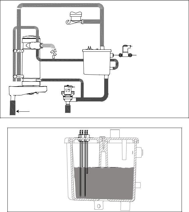
Water system
The water level in the evaporator is controlled by a fill solenoid (Fig 13) and level detecting sensors.. Water sensing rods (Fig. 14) extend down into the reservoir at the end of the evaporator assembly.. The system works via electrical conductivity as follows:
One of the longest probes is a common.. When water is between any of the other probes and the common, the PC board will sense the activation.. During normal operation, the water level rises and falls between the Normal High and Normal Low sensors.. As water is consumed to make ice, the level will fall until the Normal Low sensor is exposed, triggering the water feed solenoid on.. Water will fill until the Normal High sensor is activated..
Note: The potable water dissolved solids content must be greater than 10 ppm for the water control system to function properly.. If using reverse osmosis water filtration system, ensure T..D..S level is greater than 10 ppm..
Fig. 13 – Water system diagram
 VENT
VENT
ICE
NOZZLE
EVAPORATOR
CLEANING CUP
|
RESERVOIR FILL |
|
SOLENOID |
WATER |
WATER SUPPLY |
RESERVOIR |
3/8" FPT, 45-90 F (7-32 C) |
|
10-70 PSI (69-483 KPA) |
DRAIN PAN
TO DRAIN CUP 
Fig. 14 – Water level diagram
B COMMON |
|
|
C HIGH |
|
|
A ALARM LOW |
|
|
D LOW |
C |
NORMAL OPERATING RANGE |
|
D |
B 


 A
A
16 |
25CI425A/W, 25HI425A, 50CI425A/W, 50HI425A |
 Loading...