


Follett 7FS100AIWNFSTCC, 15FS100AIWNFSTCC, 15CI100AIWNFSTCC, 15CI100ANWCFST00, 15CI100AIWNFST00 User Manual
...Countertop and Freestanding Ice and Water Dispenser with Chewblet® Ice Machine
7CI100A, 7FS100A, 15CI100A, 15FS100A
Installation, Operation and Service Manual
Serial numbers after K70778
7FS100A 7CI100A
15FS100A 15CI100A
Welcome to Follett
Follett equipment enjoys a well-deserved reputation for excellent performance, long-term reliability and outstanding after-the-sale support. To ensure that this equipment delivers that same degree of service, review this guide carefully before you begin your installation.
Should you need technical help, please call our Technical Service group at (877) 612-5086 or (610) 252-7301.
Please have your model number, serial number and complete and detailed explanation of the problem when contacting Technical Service.
Getting Started
After uncrating and removing all packing material, inspect the equipment for concealed shipping damage. All freight is to be inspected upon delivery. If visible signs of damage exist, please refuse delivery or sign your delivery receipt "damaged." Follett Customer Service must be notified within 48 hours. Wherever possible, please include detailed photos of the damage with the original packaging so that we may start the freight claim process.
801 Church Lane • Easton, PA 18040, USA |
Installation and Service Videos: |
Toll free (877) 612-5086 • +1 (610) 252-7301 |
www.follettice.com/servicevideolibrary |
www.follettice.com |
00951640R18 |

Contents
Welcome to Follett. . . . . . . . . . . . . . . . . . . . . . . . . . . . . . . . . . . . . . . . . . . . . . . . . . . . . . . . . . . . . . . . . . . . . . . . . . . . . |
. |
1 |
|
Getting Started. . . . . . . . . . . . . . . . . . . . . . . . . . . . . . . . . . . . . . . |
. |
1 |
|
Before You Begin . . . . . . . . . . . . . . . . . . . . . . . . . . . . . . . . . . . . . . . |
|
3 |
|
Important Safety Information . . . . . . . . . . . . . . . . . . . . . . . . . . . . . . . . . . |
|
4 |
|
Specifications. . . . . . . . . . . . . . . . . . . . . . . . . . . . . . . . . . . . . . . . . |
|
4 |
|
Dimensions.. . . . . . . . . . . . . . . . . . . . . . . . . . . . . . . . . . . . . . . . |
|
4 |
|
Ambient Information. . . . . . . . . . . . . . . . . . . . . . . . . . . . . . . . . . . . . . 4 |
|||
Plumbing . . . |
. . . . . . . . . . . . . . . . . . . . . . . . . . . . . . . . . . . . . . |
|
4 |
Specifications. . . . . . . . . . . . . . . . . . . . . . . . . . . . . . . . . . . . . . . . . |
|
5 |
|
Water . . . . . . . . . . . . . . . . . . . . . . . . . . . . . . . . . . . . . . . . . . . |
|
5 |
|
Clearances . |
. . . . . . . . . . . . . . . . . . . . . . . . . . . . . . . . . . . . . . . |
|
5 |
Electrical. . |
. . . . . . . . . . . . . . . . . . . . . . . . . . . . . . . . . . . . . . . . |
|
5 |
Refrigeration. |
. . . . . . . . . . . . . . . . . . . . . . . . . . . . . . . . . . . . . . . |
. |
5 |
Heat Rejection . . . . . . . . . . . . . . . . . . . . . . . . . . . . . . . . . . . . . . . |
. |
5 |
|
7 Series Detailed Drawing. . . . . . . . . . . . . . . . . . . . . . . . . . . . . . . . . . . |
|
6 |
|
15 Series Detailed Drawing. . . . . . . . . . . . . . . . . . . . . . . . . . . . . . . . . . |
. |
7 |
|
Installation. . . . . . . . . . . . . . . . . . . . . . . . . . . . . . . . . . . . . . . . . . . 8
Countertop Installation. . . . . . . . . . . . . . . . . . . . . . . . . . . . . . . . . . . . . 8
Freestanding Installation. . |
. . . . . |
. . . . . . . . . . . . . . . . . . . . . . . . . . . . |
|
9 |
||
Maintenance/Cleaning Mode. . . . . . . . . . . . . . . . . . . . . . . . . . . . . . . . . . . 12 |
||||||
Accessing Internal Components. . |
. . . . . . . . . . . . . . . . . . . . . . . . . . . . . . . |
|
12 |
|||
Filter Display Indicator Activation. . |
. . . . . . . . . . . . . . . . . . . . . . . . . . . . . . |
. |
13 |
|||
Cleaning and Sanitizing Procedure. |
. . . . . . . . . . . . . . . . . . . . . . . . . . . . . . |
|
14 |
|||
Service. . . . . . . . . . . . . . . . . . . . . . . . . . . . . . . . . . . . . . . . . . . |
. |
15 |
||||
LED Indicator Description. |
. . . . . . |
. . . . . . . . . . . . . . . . . . . . . . . . . . . |
|
15 |
||
Evaporator Disassembly.. . . . . . . . . . . . . . . . . . . . . . . . . . . . . . . . . . . |
|
16 |
||||
Evaporator Assembly. . . . . . . . . . . . . . . . . . . . . . . . . . . . . . . . . . . . |
. |
19 |
||||
Water Feed Schematic. . |
. . . . . . . . . . . . . . . . . . . . . . . . . . . . . . . . . . |
|
23 |
|||
Bin Melt Water/Evaporator Feed/Clean Out System Schematic . . . . . . . . . . . . . . . . . . . . |
|
24 |
||||
Vent System Schematic. . . . . . . . . . . . . . . . . . . . . . . . . . . . . . . . . . . . 24 |
||||||
Refrigeration Schematic. . |
. . . . . . . . . . . . . . . . . . . . . . . . . . . . . . . . . |
. |
25 |
|||
Condenser Fan Motor Removal (7 Series Shown) . . . . . . . . . . . . . . . . . . . . . . . . . |
|
26 |
||||
User Interface Display Identification.. . . . . . . . . . . . . . . . . . . . . . . . . . . . . . |
|
27 |
||||
Electrical Wiring Diagram. |
. . . . . . . . . . . . . . . . . . . . . . . . . . . . . . . . . . |
|
29 |
|||
Parts. . . . . . . . . . . . . . . . . . . . . . . . . . . . . . . . . . . . . . . . . . . . |
. |
30 |
||||
7 Series Exterior.. . . . . . . . . . . . . . . . . . . . . . . . . . . . . . . . . . . . . . |
|
30 |
||||
7 Series Interior . . . . . . . . . . . . . . . . . . . . . . . . . . . . . . . . . . . . . . |
. |
32 |
||||
15 Series Exterior. . |
. . . . . . . . . . . . . . . . . . . . . . . . . . . . . . . . . . . . |
|
34 |
|||
15 Series Interior . . . . . . . . . . . . . . . . . . . . . . . . . . . . . . . . . . . . . . |
|
36 |
||||
7 Series Bin Assembly. . . . . . . . . . . . . . . . . . . . . . . . . . . . . . . . . . . . |
|
38 |
||||
15 Series Bin Assembly. . . . . . . . . . . . . . . . . . . . . . . . . . . . . . . . . . . . 40 |
||||||
Evaporator Assembly. . . . . . . . . . . . . . . . . . . . . . . . . . . . . . . . . . . . |
. |
42 |
||||
Base Stand. . |
. . . . . . . . . . . . . . . . . . . . . . . . . . . . . . . . . . . . . . |
. |
44 |
|||
2 7CI100A/7FS100A, 15CI100A/15FS100A
Before You Begin
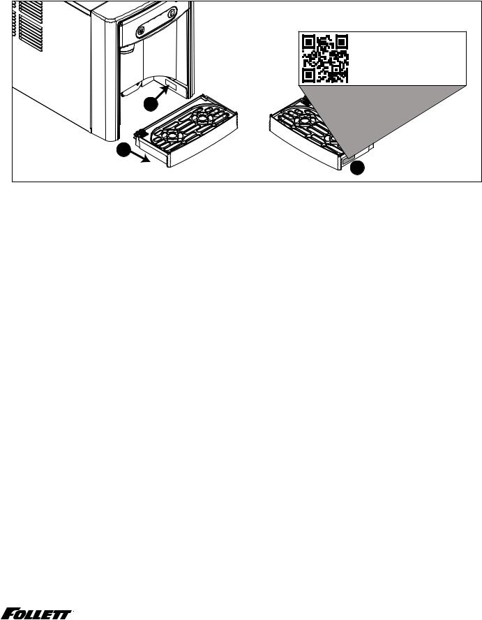
If needed, the serial number of your dispenser can be found by removing the drip tray and locating the serial number label . A QR Code is located on the right hand side of the drip tray . This code allows you to access manuals, technical bulletins, and on-line training related to the 7 Series and 15 Series dispensers.
Scan to access technical |
documentation or visit |
www.follettice.com/7and15seriesdocs |
00981100R01 |
2 |
1 |
3 |
Check your paperwork to verify that you received the correct dispenser. Follett configuration numbers are designed to provide information about the type of dispenser you are receiving. The following is an explanation of the different model numbers.
|
|
7 |
|
|
CI |
|
100 |
|
|
A |
|
|
|
|
|||||
|
|
|
|
|
|
|
|
|
|
|
|
|
|
|
|
|
|
|
|
|
|
|
|
|
|
|
|
|
|
|
|
|
|
|
|
|
|
|
|
|
|
|
|
|
|
|
|
|
|
|
|
|
|
|
|
|
|
|
|
|
|
|
|
|
|
|
|
|
|
|
|
|
|
|
|
|
|
|
|
Dispenser Storage |
|
|
Configuration |
|
|
Icemaker Capacity |
|
Condenser |
|||||||||||
Capacity |
|
|
|
|
|
||||||||||||||
|
|
|
|
|
|
|
|
|
|
|
|
|
|
|
|
|
|||
|
|
|
|
|
|
|
|
|
|
|
|
|
|||||||
7 lb (3.1 kg) |
CI |
Countertop |
100 |
lbs (45.3 kg) per day |
A |
Air-cooled |
|||||||||||||
15 lb (6.8 kg) |
FS |
Freestanding |
|||||||||||||||||
|
|
|
|
|
|
|
|
|
|
||||||||||
|
|
|
|
|
|
|
|
|
|
|
|
|
|
|
|
|
|
|
|
7CI100A/7FS100A, 15CI100A/15FS100A |
3 |

Important Safety Information
Please read and adhere to the following safety information while installing, using, or servicing your Follett Ice Dispenser.
1.Always disconnect power before servicing the dispenser.
2.Ice is slippery. Maintain counters and floors around dispenser in a clean and ice-free condition.
3.Ice is food. Follow the recommended cleaning and sanitizing instructions to maintain cleanliness of delivered ice.
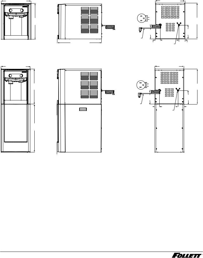
Specifications
Dimensions
|
7CI100A |
|
7FS100A |
15CI100A |
15FS100A |
Width |
14.50" (40 cm) |
14.50" (36.8 cm) |
14.50" (40 cm) |
14.50" (40 cm) |
|
|
|
|
|
|
|
Depth |
22.12" (56.2 cm) |
22.12" (56.2 cm) |
23.50" (59.7 cm) |
23.50" (59.7 cm) |
|
|
|
|
|
|
|
Height |
17.50" (44.5 cm) |
41.88" |
(106.4 cm) |
22.50" (57.2 cm) |
46.75" (118.7 cm) |
|
|
|
|
|
|
Unit Shipping Weight |
90 lb (41 kg) |
120 lb |
(54.4 kg) |
100 lb (45.4 kg) |
130 lb (60 kg) |
|
|
|
|
|
|
Ambient Information
 CAUTION!
The 7CI100A/7FS100A and 15CI100A/15FS100A are for indoor use only. Designed for commercial use. Follett is not able to provide in-house services for residential installations.
|
Maximum* |
|
|
Minimum* |
|
|
|
|
|
Air Temperature† |
100 F (38 C) |
|
50 |
F (10 C) |
Water Temperature |
90 F (32.2 C) |
|
40 |
F (4.5 C) |
|
|
|
|
|
Water Pressure |
70 psi (483 kpa) |
|
10 psi (69 kpa) |
|
|
|
|
|
|
Relative Humidity |
|
55% at 78 F (25.5 C) |
||
|
|
|
|
|
* Use outside of these limitations is misuse and will void warranty.
† Best performance is achieved between 80 F (27 C) and 50 F (10 C).
Plumbing
§Water Inlet: 1/4" MPT
§Optional Drain Accessory Kit (item# 00956375 or 00981977): 1/2" ID tubing
§Water shut-off recommended within 5 ft (1.5 m) of dispenser
4 7CI100A/7FS100A, 15CI100A/15FS100A

Specifications
Water
 WARNING!
Connect to potable water supply only.
§Water Mineral Content:
–TDS: greater than 5 ppm (mg/l) but less than 400 ppm (mg/l)
–Hardness: Less than 200 mg/l (12 gpg)
§Not recommended for use with softened water
Clearances
§ 3" (7.62 cm) behind and on each side of dispenser for electrical and connection and ventilation
Electrical
§115V, 60 Hz, 1 phase, 5A, maximum fuse 15A
§Connect to dedicated 15A circuit, fuse or breaker
§Must be grounded - requires 3-prong outlet. Do not remove ground.
Refrigeration


 WARNING!
Do not damage the refrigerant circuit. Refrigerant can cause personal injury and/or damage dispenser.
§ Refrigerant R134a – 5.0 ounces (142 grams)
Heat Rejection
§ 1700 BTU/hr (498 W)
7CI100A/7FS100A, 15CI100A/15FS100A |
5 |
Specifications (continued) |
|
|
|
|
7 Series Detailed Drawing |
|
|
|
|
Countertop models |
|
|
|
|
14.50" (36.8 cm) |
|
|
|
14.5" (36.8 cm) |
|
NEMA 5-15 |
L2 |
|
|
17.50" |
right angle |
G |
17.50" |
|
(115 V only) |
L1 |
|
||
(44.5 cm) |
|
|
|
(44.5 cm) |
|
|
|
6.75" |
6.88" |
|
|
|
(17.2 cm) |
(17.5 cm) |
|
power cord |
|
|
22.12" (56.2 cm) |
2.50" |
1/4" MPT |
3.00" |
|
|||
|
(6.4 cm) |
water inlet |
(7.6 cm) |
Freestanding models |
|
|
|
14.50" (36.8 cm) |
|
|
14.5" (36.8 cm) |
|
NEMA 5-15 |
|
|
17.50" |
right angle |
L2 |
17.50" |
(115 V only) |
L1 |
||
|
|
G |
|
(44.5 cm) |
|
|
(44.5 cm) |
|
|
6.75" |
6.88" |
|
|
(17.2 cm) |
(17.5 cm) |
power cord |
|
|
2.50" |
|
3.00" |
(6.4 cm) |
1/4" MPT |
(7.6 cm) |
|
|
|
|
water inlet |
|
24.38" (61.9 cm)
 22.12" (56.2 cm)

6 7CI100A/7FS100A, 15CI100A/15FS100A

Specifications (continued)
15 Series Detailed Drawing
Countertop models |
14.50" (36.8 cm) |
22.50" |
(57.2 cm) |
Freestanding models |
14.50" (36.8 cm) |
22.38" |
(56.8 cm) |
46.75" |
(118.7 cm) |
24.38" |
(61.9 cm) |
23.50" (59.7 cm) |
22.12" (56.2 cm) |
23.50" (59.7 cm) |
22.12" (56.2 cm) |
NEMA 5-15 right angle (115 V only)
power cord
|
14.50" (36.8 cm) |
L2 |
|
G |
22.50" |
L1 |
|
|
(57.2 cm) |
6.75" |
6.88" |
(17.2 cm) |
(17.5 cm) |
2.50" |
1/4" MPT |
|
3.00" |
|
|||
(6.4 cm) |
water inlet |
|
(7.6 cm) |
NEMA 5-15 right angle (115 V only)
power cord
|
14.50" (36.8 cm) |
|
L2 |
|
|
G |
|
|
L1 |
|
22.50" |
|
|
(57.2 cm) |
6.75" |
|
6.88" |
(17.2 cm) |
|
(17.5 cm) |
2.50" |
1/4" MPT |
3.00" |
(6.4 cm) |
water inlet |
(7.6 cm) |
7CI100A/7FS100A, 15CI100A/15FS100A |
7 |
Installation
 CAUTION!
No service or maintenance should be performed until the technician has thoroughly read this service manual. Except for routine cleaning and sanitizing, only qualified technicians should attempt to service or maintain this equipment.
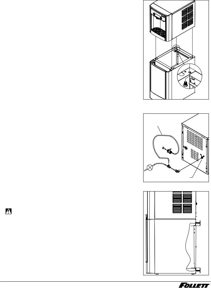
Countertop Installation
The 7 Series countertop model is designed to fit on counters underneath standard mounted cabinets, this does not apply to 15 Series models. See page 4 for dimensions. Installation instructions for freestanding model may be found on page 9.
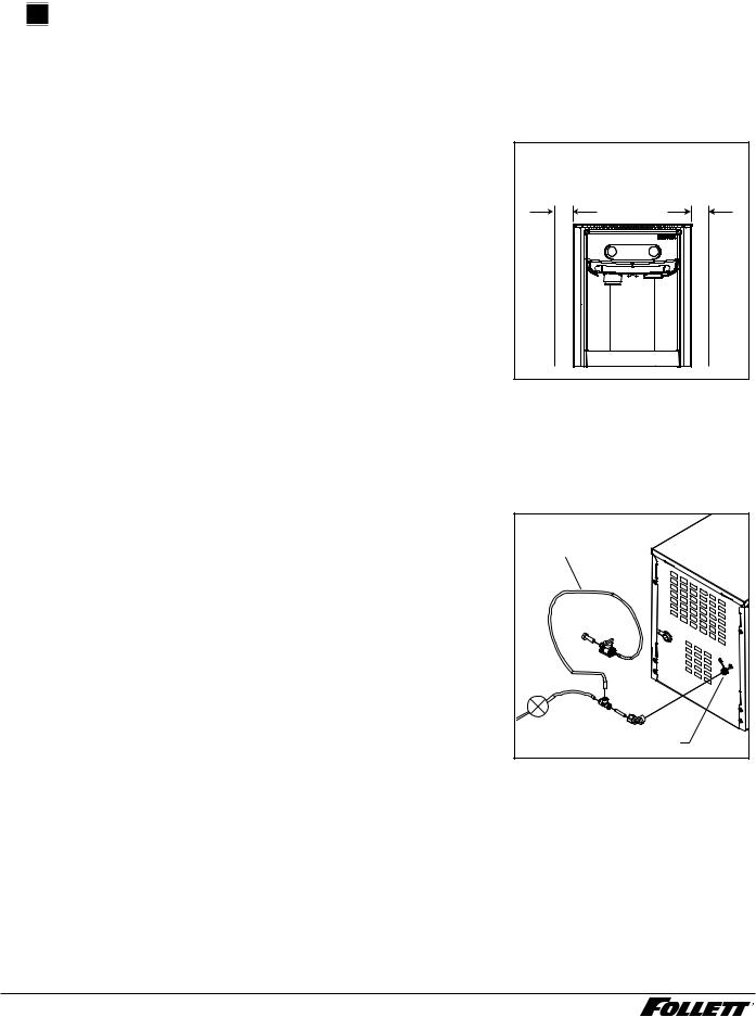
1.A clearance of at least 3" (7.62 cm) is required behind and on each side of the dispenser for electrical connection and ventilation
(Fig. 1).
2.Rough-in the electrical service and water line.
§Electrical: 115 V, single phase, 15A receptacle required. The dispenser has an integral 8 ft (2.4 m) cord and plug.
§Water: supply line (with shut-off valve) connects to the dispenser's 1/4" MPT inlet.
NOTICE!
If installing optional Drip Tray Drain Kit or Leg Accessory, complete those steps before proceeding. Refer to instructions included with the Drip Tray Drain Kit, or see page 9 for Leg Accessory instructions.
3.Connect water line. Recommended routing (Fig. 2) allows easy access to water for cleaning and sanitizing procedure.
4.If installing the optional internal water filter*, please see
Maintenance/Cleaning Mode on page 12 before proceeding. If not, proceed to step 5.
*If your dispenser has the internal water filter option, the water filter must be installed for the dispenser to operate. Because internal components will need to be accessed for both procedures, Follett recommends installing the water filter just prior to initial sanitizing.
5.Connect power supply.
6.Sanitize the dispenser prior to use (see the Initial Sanitizing Kit instructions shipped with this unit).
Fig. 1
countertop models
minimum 3" (7.62 cm) clearance required
Fig. 2
3' (91.4 cm) |
Plug |
Valve |
1/4" MPT |
8 7CI100A/7FS100A, 15CI100A/15FS100A
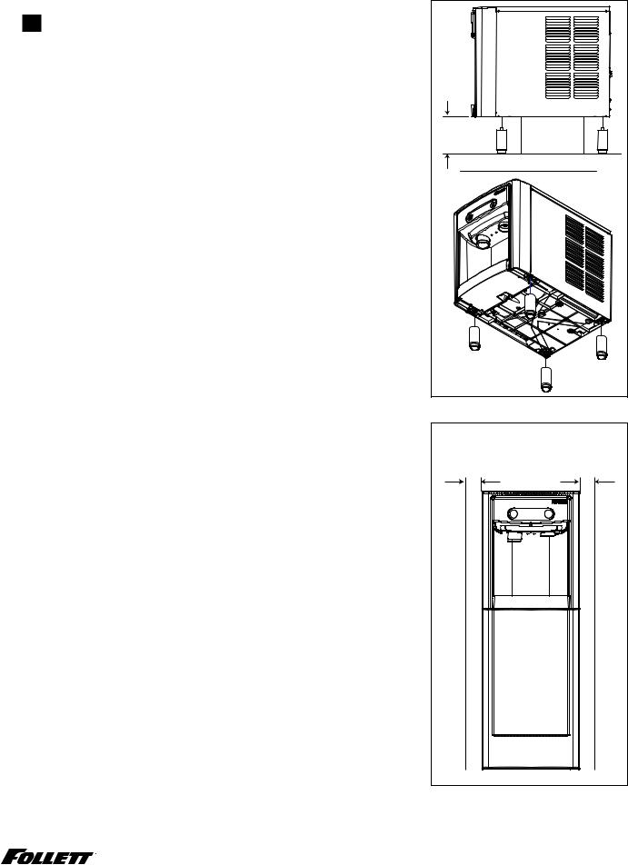
Optional Leg Accessory Installation |
Fig. 3 |
 CAUTION!
Use caution when tipping the dispenser during leg installation. Do not lay unit on back or side. DO NOT EXCEED 30° angle. Tipping more than 30° can result in compressor malfunction.
1.If installing optional 4" Leg Accessory (item# 00956300), place a 5" (12.7 cm) spacer underneath the dispenser to ease installation.
2.Remove four plastic, thread-protecting plugs from bottom of dispenser.
3.Screw each leg into chassis (Fig. 3).
5" (12.7 cm) |
spacer |
min. |
|
Freestanding Installation |
Fig. 4 |
|
Installation instructions for countertop model may be found on Countertop |
freestanding models |
|
Installation on page 8. |
||
|
||
1. A clearance of at least 3" (7.62 cm) is required behind and on |
minimum 3" (7.62 cm) |
|
clearance required |
||
each side of the dispenser for electrical connection and ventilation |
|
|
(Fig. 4). |
|
2. Rough-in the electrical service and water line.
§ Electrical: 115 V, single phase, 15A receptacle required. The dispenser has an integral 8 ft (2.4 m) cord and plug.
§Water: supply line (with shut-off valve) connects to the dispenser's 1/4" MPT inlet.
NOTICE!
If installing optional Leg Accessory, complete those steps before proceeding. See page 11 for Leg Accessory instructions.
7CI100A/7FS100A, 15CI100A/15FS100A |
9 |
3.Remove four plastic, thread-protecting plugs from bottom of dispenser.
4.Attach dispenser to base stand with supplied hardware (Fig. 5).
NOTICE!
If installing optional Drip Tray Drain Kit, refer to instructions included with the Drip Tray Drain Kit.
Fig. 5
X4 |
5. Connect water line. Recommended routing (Fig. 6) allows easy access |
Fig. 6 |
|
|
to water for cleaning and sanitizing procedure. |
|
6. If installing the optional internal water filter*, please see Optional |
3' (91.4 cm) |
|
|
Internal Water Filter Installation on page 11 before proceeding. |
|
|
|
|
|
If not, proceed to step 7. |
|
|
* If your dispenser has the internal water filter option, the water filter must be |
|
|
installed for the dispenser to operate. Because internal components will need to |
Plug |
|
be accessed for both procedures, Follett recommends installing the water filter |
|
|
just prior to initial sanitizing. |
|
7. |
Connect power supply. |
Valve |
|
||
8. Sanitize the dispenser prior to use (see the Initial Sanitizing Kit |
|
|
|
instructions shipped with this unit). |
|
|
|
1/4" MPT |
9. Secure unit to wall or cove molding with supplied bracket (Fig. 7) to |
Fig. 7 |
|
|
prevent tipping. |
|
Note: Fasteners must be supplied by installer.
WARNING!
Freestanding unit must be secured to wall to prevent tipping. Failure to do could result in personal injury or damage to the unit.
10 7CI100A/7FS100A, 15CI100A/15FS100A
Optional Leg Accessory Installation |
Fig. 8 |
|||||||||
1. If installing optional 6" Leg Accessory (item# 00956318), tilt or lay |
|
|
|
|
|
|
|
|
|
|
|
|
|
|
|
|
|
|
|
|
|
base stand on side and screw each leg into stand (Fig. 8). |
|
|
|
|
|
|
|
|
|
|
|
|
|
|
|
|
|
|
|
|
|
|
|
|
|
|
|
|
|
|
|
|
|
|
|
|
|
|
|
|
|
|
|
|
|
|
|
|
|
|
|
|
|
|
|
|
|
|
|
|
|
|
|
|
|
|
|
|
|
|
|
|
|
|
|
|
|
|
|
|
|
|
|
|
|
|
|
|
|
|
|
|
|
|
|
|
|
|
|
|
|
|
|
|
|
|
|
|
|
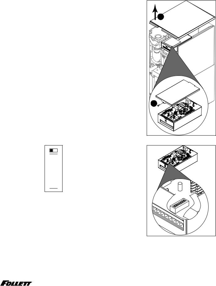
Optional Internal Water Filter Installation
If your dispenser has the internal water filter option, the water filter must be installed for the dispenser to operate. Because internal components will need to be accessed for both procedures, Follett recommends installing the water filter just prior to initial sanitizing.
1.If installing the optional internal water filter, please complete the steps shown in Accessing Internal Components on page 12 before proceeding.
2.Lift and remove the top panel, set aside (Fig. 9.1).
3.Remove two screws (Fig. 9.2) and remove left side panel.
4.Install filter as shown. Turn filter clockwise until it is fully seated
(Fig. 9.3).
Fig. 9
2 |
1 |
|
|
|
3 |
7CI100A/7FS100A, 15CI100A/15FS100A |
11 |

Maintenance/Cleaning Mode
Cleaning Mode (Dispensing Disabled) - Use when cleaning surface
Entering Cleaning Mode disables the User Interface and allows you to clean the outside of the dispenser without accidentally dispensing water or ice.
1.To enter Cleaning Mode, press and immediately release the maintenance/clean switch (Fig. 10.1) so that only "FRESH FILTERED ICE AND WATER" displays in the user interface
(Fig. 10.2).
2.To exit Cleaning Mode, press and immediately release the maintenance/clean switch so that the ice and water icons also display in the user interface.
Maintenance Mode (All Operations Disabled) - Use when cleaning ice machine
Entering Maintenance Mode disables all operations and allows you to safely clean and/or sanitize the ice machine and dispenser.
1.To enter Maintenance Mode, press and hold the maintenance/ clean switch (Fig. 10.3) until  displays in the user interface
(Fig. 10.4).
2.To exit Maintenance Mode, press and hold the maintenance/clean switch until  no longer displays in the user interface.
Note: Entering and exiting Maintenance Mode will reset the six-month periodic maintenance reminder.
Fig. 10 |
2 |
1 |
4 |
3 |
Accessing Internal Components |
|
|
|
CAUTION! |
Fig. 11 |
|
|
|
|
Except for routine cleaning and sanitizing, only qualified |
|
|
technicians should attempt to service or maintain this equipment. |
|
1. |
Press and hold the maintenance/clean switch (Fig. 10.1) until |
|
|
displays in the user interface (Fig. 10.2). |
|
2. |
Remove (unscrew) chrome ice dispenser chute (Fig. 11.1). |
1 |
3. |
Remove the drip tray (Fig. 11.2). |
|
4. |
Remove the two screws (Fig. 11.3) on the front panel (behind the |
3 |
|
drip tray). |
|
5. |
Remove and set aside the front panel (Fig. 11.4). Do not |
2 |
|
disengage the plug on the back of the User Interface or the |
|
|
tubing at the water dispenser chute (if so equipped). |
|
|
|
4 |
12 |
7CI100A/7FS100A, 15CI100A/15FS100A |
|
Filter Display Indicator Activation
If you purchased your dispenser with a Follett filter, the filter display indicator activation has been preset at the factory.
If you are using an “after market filter,” an adjustment may be made to activate the “Fresh Filtered Ice & Water” display.
Activating “Fresh Filtered Ice & Water”
1.Remove the front panel as explained in Accessing Internal Components on page 12 then refer to Fig. 12.
2.Remove top panel (Fig. 12.1).
Note: For 15 Series dispensers, the right side panel must also be
removed.
3.Remove (1) screw and top of control board enclosure (Fig. 12.2).
4.Locate the DIP switches on the dispenser's control board (Fig. 13). Use a fine-pointed object to move the “Filter” DIP switch (DIP switch #3) to the ON position.
Deactivating the Six-Month Maintenance/Filter Change Reminder
1.Use a fine-pointed object to move the “PM” DIP switch (DIP switch #8) to the ON position.
Not used (OFF position) Ice only No internal filter
Not used (OFF position) Not used (OFF position)
15 minute delay Not used (OFF position) Six-month PM enabled
OFF ON
8 7 6 5 4 3 2 1

Ice and water
Internal filter supplied or to display "Fresh Filtered"
30 minute delay
Six-month PM disabled
Fig. 12
1 |
2 |
Fig. 13
7CI100A/7FS100A, 15CI100A/15FS100A |
13 |
Cleaning and Sanitizing Procedure
Cleaning and sanitizing should be performed at least every 6 months (more often if local water conditions dictate).
WARNING!
§Place the dispenser in Maintenance Mode prior to servicing or cleaning the ice machine. See Maintenance/Cleaning Mode on page 12.
§For protection, rubber gloves and safety goggles (and/or face shield) should be worn when handling SafeCLEAN Plus™.
§Do not use bleach, it will damage the dispenser.
Required Supplies
§7 Series: Follow the directions on the SafeCLEAN Plus packaging to mix 3 gal (11.4 L) of Follett SafeCLEAN Plus solution. Use 100 F (38 C) water. 15 Series: Follow the directions on the SafeCLEAN Plus packaging to mix 6 gal (22.7 L) of Follett SafeCLEAN Plus solution. Use 100 F (38 C) water.
§Funnel, bucket, 100 F (38 C) potable water
Ice machine and Dispenser
1.Dispense all the ice out of the unit.
2.Press and hold maintenance/clean switch until  displays in the user interface to enter Maintenance Mode.
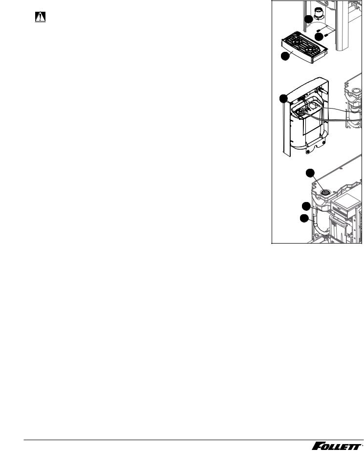
3.Remove (unscrew) chrome ice dispense chute (Fig. 14.1).
4.Remove drip tray (Fig. 14.2).
5.Remove (2) screws located behind the drip tray (Fig. 14.3).
6.Move front panel and place on top or beside unit (Fig. 14.4).
7.Remove plug cap from the end of drain tube (Fig. 14.5) and lower tube to drain water into bucket. After the system has been drained of water replace plug cap in drain tube.
8.Secure tube in holder.
9.Remove cap from bin lid cover (Fig. 14.6).
Fig. 14
1 |
3 |
2 |
4 |
6 |
7 |
5 |
10.Screw bin lid cover cap onto ice discharge chute (Fig. 14.7).
11.Pour SafeCLEAN Plus solution into bin lid access spout until solution reaches the spout neck.
12.Allow the SafeCLEAN Plus solution to remain in unit for 15 minutes.
13.While machine is cleaning, remove top and right side panel to access and clean air-cooled condenser.
14.Submerge ice dispense chute in the remainder of SafeCLEAN Plus solution for 2 minutes. Rinse with clean, potable water.
15.Drain system by lowering drain tube into bucket.
16.Secure drain tube into holder.
17.Fill and drain twice with potable water. Secure drain tube.
18.Place a bucket under the dispense chute and remove cap. Note: Some SafeCLEAN Plus solution will remain and drain out when cap is removed. Reposition cap on bin lid spout.
19.Reinstall front panel, ice dispense chute, and drip tray.
20.Press and hold maintenance/clean switch to exit Maintenance Mode.
14 7CI100A/7FS100A, 15CI100A/15FS100A

User Interface and Exterior Cabinet
1.Press and release maintenance/clean switch so that only "FRESH FILTERED ICE AND WATER" displays in the user interface to enter Cleaning Mode (and disable dispensing).
2.Plastic parts, including the user interface, can be cleaned with a non-abrasive glass cleaner. Clean stainless steel panels with stainless steel cleaner.
3.Press and release maintenance/clean switch to put unit back into service.
Service
LED Indicator Description
The LED Indicator is located behind the front panel.
Fig. 15
|
|
|
|
|
|
|
Clean |
PM Drip tray Water leak HI press HI amps Service Maint Low water Time delay Sleep cycle Making ice Low bin Power ON |
|
|
|
|
|
|
|
|
|
||
|
|
|
||
LED Name |
LED Color |
Description |
||
|
|
|
||
Clean |
Green |
The dispenser is in Cleaning Mode. Dispenser is disabled to allow for cleaning of front panel. |
||
|
|
|
See Maintenance/Cleaning Mode on page 12. |
|
— |
N/A |
Not used. |
||
|
|
|
||
PM |
Red |
Six-month periodic maintenance required. |
||
|
|
|
||
Drip tray |
Red |
Drip tray full. |
||
|
|
|
||
Water leak |
Red |
Internal leak in dispenser. |
||
|
|
|
||
High amps |
Red |
Auger gearmotor has exceeded 0.55A. The HI amps and Time delay LEDs will illuminate, |
||
|
|
|
the machine will shut down for one hour, the LEDs will turn off, and the machine will resume |
|
|
|
|
normal operation. |
|
|
|
|
||
Service |
Red |
8000 hour bushing check (call Follett technical service group at (877) 612-5086 or |
||
|
|
|
+1 (610) 252-7301). |
|
|
|
|
||
Maintenance |
Yellow |
Enter Maintenance Mode by pressing and holding maintenance/clean switch for 5 seconds. |
||
|
|
|
Unit will not make or dispense ice. |
|
Low water |
Yellow |
Insufficient water supply to machine or no low bin LED upon startup. |
||
|
|
|
||
Time delay |
Yellow |
Ice production will not resume for at least 15 minutes after a full bin is achieved and a |
||
|
|
|
minimum amount of dispense activity has elapsed. |
|
Sleep cycle |
Green |
After a full bin and 10 minutes of non-use, the unit goes into standby and will not produce ice |
||
|
|
|
until either: |
|
|
|
|
7 Series:12 hours has elapsed, 15 Series: 4 hours has elapsed or ice or water has dispensed. |
|
Making ice |
Green |
Gearmotor, compressor, and fan motor energized. |
||
|
|
|
||
Low bin |
Green |
Bin switch closed calling for ice. |
||
|
|
|
||
Power on |
Green |
Power supplied to unit. |
||
|
|
|
|
|
7CI100A/7FS100A, 15CI100A/15FS100A |
15 |
 Loading...