


Ice and Sparkling Water Dispenser with Chewblet® Ice Icemaker
7CI100A, 7FS100A, 15CI100A, 15FS100A
Installation, Operation and Service Manual
7FS100A |
7CI100A |
15FS100A |
15CI100A |
Following installation, please forward this manual to the appropriate operations person.
801 Church Lane • Easton, PA 18040, USA |
Order parts online: |
Toll free (877) 612-5086 • +1 (610) 252-7301 |
www.follettice.com |
www.follettice.com |
01156496R01 |

Follett 7/15 Series Sparkling - Installation Checklist
Before beginning:
Separate boxes for dispenser, carbonator, installation kit, and accessories.
Customer-supplied, beverage-grade CO2 cylinder is present and full.
Assemble system:
Sparkling Water, Still Water, and power cord installed between carbonator and dispenser.
Water Block ood protection device set to “2” and installed vertically after tee on the water line to the carbonator water inlet.
ShockBlok water pressure regulator installed after Water Block and before carbonator water inlet.
CO2 regulator set to 60 psi.
Turn on water, plug in dispenser – leave carbonator and CO2 off:
No leaks in plumbing connections. Check before reinstalling dispenser side panel.
Carbonator air is bled according to installation instructions.
Turn on carbonator and CO2:
Sparkling and Still Water ow from correct button press.
Carbonator pump cycles on and off between Sparkling Water dispenses.
Perform 4 separate 16 oz. Sparkling Water dispenses.
Notes: Allow carbonator pump to cycle off between dispenses.
Do not exceed 32 oz. continuous sparkling dispense.
Allow at least 1 hour for chiller to reach optimal temperature.
2 Sparkling Ice and Water Dispenser 7CI100A/7FS100A, 15CI100A/15FS100A

Contents |
|
About Follett Sparkling Water . . . . . . . . . . . . . . . . . . . . . . . . . . . . . . . . . . . . . . . . . . . . . . . . . . . . . . . . . . . . . . . . . . . . . |
4 |
Welcome. . . . . . . . . . . . . . . . . . . . . . . . . . . . . . . . . . . . . . . . . . . . . . . . . . . . . . . . . . . . . . . . . . . . . . . . . . . . . . . . . . . . . . |
4 |
Before You Begin. . . . . . . . . . . . . . . . . . . . . . . . . . . . . . . . . . . . . . . . . . . . . . . . . . . . . . . . . . . . . . . . . . . . . . . . . . . . . . . |
5 |
Important Safety Information. . . . . . . . . . . . . . . . . . . . . . . . . . . . . . . . . . . . . . . . . . . . . . . . . . . . . . . . . . . . . . . . . . . . . |
6 |
Specifications. . . . . . . . . . . . . . . . . . . . . . . . . . . . . . . . . . . . . . . . . . . . . . . . . . . . . . . . . . . . . . . . . . . . . . . . . . . . . . . . . . |
6 |
Dispenser Dimensions. . . . . . . . . . . . . . . . . . . . . . . . . . . . . . . . . . . . . . . . . . . . . . . . . . . . . . . . . . . . . . . . . . . . . . . . . |
6 |
Carbonator Dimensions. . . . . . . . . . . . . . . . . . . . . . . . . . . . . . . . . . . . . . . . . . . . . . . . . . . . . . . . . . . . . . . . . . . . . . . . |
6 |
Ambient Information.. . . . . . . . . . . . . . . . . . . . . . . . . . . . . . . . . . . . . . . . . . . . . . . . . . . . . . . . . . . . . . . . . . . . . . . . . . |
6 |
Plumbing. . . . . . . . . . . . . . . . . . . . . . . . . . . . . . . . . . . . . . . . . . . . . . . . . . . . . . . . . . . . . . . . . . . . . . . . . . . . . . . . . . . |
6 |
Specifications. . . . . . . . . . . . . . . . . . . . . . . . . . . . . . . . . . . . . . . . . . . . . . . . . . . . . . . . . . . . . . . . . . . . . . . . . . . . . . . . . . |
7 |
Water . . . . . . . . . . . . . . . . . . . . . . . . . . . . . . . . . . . . . . . . . . . . . . . . . . . . . . . . . . . . . . . . . . . . . . . . . . . . . . . . . . . . . . |
7 |
Clearances ................................................................................. |
7 |
Electrical.. . . . . . . . . . . . . . . . . . . . . . . . . . . . . . . . . . . . . . . . . . . . . . . . . . . . . . . . . . . . . . . . . . . . . . . . . . . . . . . . . . . |
7 |
Refrigeration.. . . . . . . . . . . . . . . . . . . . . . . . . . . . . . . . . . . . . . . . . . . . . . . . . . . . . . . . . . . . . . . . . . . . . . . . . . . . . . . . |
7 |
Heat Rejection . . . . . . . . . . . . . . . . . . . . . . . . . . . . . . . . . . . . . . . . . . . . . . . . . . . . . . . . . . . . . . . . . . . . . . . . . . . . . . . |
7 |
Chiller/Carbonator Detailed Drawing . . . . . . . . . . . . . . . . . . . . . . . . . . . . . . . . . . . . . . . . . . . . . . . . . . . . . . . . . . . . . . |
7 |
7 Series Detailed Drawing. . . . . . . . . . . . . . . . . . . . . . . . . . . . . . . . . . . . . . . . . . . . . . . . . . . . . . . . . . . . . . . . . . . . . . |
8 |
15 Series Detailed Drawing. . . . . . . . . . . . . . . . . . . . . . . . . . . . . . . . . . . . . . . . . . . . . . . . . . . . . . . . . . . . . . . . . . . . . |
9 |
Installation.. . . . . . . . . . . . . . . . . . . . . . . . . . . . . . . . . . . . . . . . . . . . . . . . . . . . . . . . . . . . . . . . . . . . . . . . . . . . . . . . . . . . |
10 |
Countertop Installation. . . . . . . . . . . . . . . . . . . . . . . . . . . . . . . . . . . . . . . . . . . . . . . . . . . . . . . . . . . . . . . . . . . . . . . . . |
10 |
Freestanding Installation. . . . . . . . . . . . . . . . . . . . . . . . . . . . . . . . . . . . . . . . . . . . . . . . . . . . . . . . . . . . . . . . . . . . . . |
12 |
Final Connections - Countertop Installation . . . . . . . . . . . . . . . . . . . . . . . . . . . . . . . . . . . . . . . . . . . . . . . . . . . . . . . |
14 |
Final Connections - Freestanding Installation .. . . . . . . . . . . . . . . . . . . . . . . . . . . . . . . . . . . . . . . . . . . . . . . . . . . . . |
16 |
Maintenance/Cleaning Mode. . . . . . . . . . . . . . . . . . . . . . . . . . . . . . . . . . . . . . . . . . . . . . . . . . . . . . . . . . . . . . . . . . . . . |
19 |
Accessing Internal Components. . . . . . . . . . . . . . . . . . . . . . . . . . . . . . . . . . . . . . . . . . . . . . . . . . . . . . . . . . . . . . . . . |
19 |
DIP-switch Settings. . . . . . . . . . . . . . . . . . . . . . . . . . . . . . . . . . . . . . . . . . . . . . . . . . . . . . . . . . . . . . . . . . . . . . . . . . . . |
20 |
NSF-approved Cleaning and Sanitizing Procedure. . . . . . . . . . . . . . . . . . . . . . . . . . . . . . . . . . . . . . . . . . . . . . . . . . |
21 |
User Interface and Exterior Cabinet Cleaning.. . . . . . . . . . . . . . . . . . . . . . . . . . . . . . . . . . . . . . . . . . . . . . . . . . . . . . |
22 |
Flow Straightener Cleaning/Sanitizing.. . . . . . . . . . . . . . . . . . . . . . . . . . . . . . . . . . . . . . . . . . . . . . . . . . . . . . . . . . . . |
22 |
Chiller/Carbonator Sanitizing Instructions. . . . . . . . . . . . . . . . . . . . . . . . . . . . . . . . . . . . . . . . . . . . . . . . . . . . . . . . . |
22 |
Service. . . . . . . . . . . . . . . . . . . . . . . . . . . . . . . . . . . . . . . . . . . . . . . . . . . . . . . . . . . . . . . . . . . . . . . . . . . . . . . . . . . . . . . |
23 |
LED Indicator Description. . . . . . . . . . . . . . . . . . . . . . . . . . . . . . . . . . . . . . . . . . . . . . . . . . . . . . . . . . . . . . . . . . . . . |
23 |
Evaporator Disassembly. . . . . . . . . . . . . . . . . . . . . . . . . . . . . . . . . . . . . . . . . . . . . . . . . . . . . . . . . . . . . . . . . . . . . . |
24 |
Evaporator Assembly. . . . . . . . . . . . . . . . . . . . . . . . . . . . . . . . . . . . . . . . . . . . . . . . . . . . . . . . . . . . . . . . . . . . . . . . . |
27 |
Condenser Fan Motor Removal (7 Series Shown) . . . . . . . . . . . . . . . . . . . . . . . . . . . . . . . . . . . . . . . . . . . . . . . . . . |
31 |
Bin Melt Water/Evaporator Feed/Clean Out System Schematic . . . . . . . . . . . . . . . . . . . . . . . . . . . . . . . . . . . . . . . . |
32 |
Vent System Schematic. . . . . . . . . . . . . . . . . . . . . . . . . . . . . . . . . . . . . . . . . . . . . . . . . . . . . . . . . . . . . . . . . . . . . . . |
32 |
Refrigeration Schematic - Dispenser. . . . . . . . . . . . . . . . . . . . . . . . . . . . . . . . . . . . . . . . . . . . . . . . . . . . . . . . . . . . . |
33 |
Water Feed Schematic.. . . . . . . . . . . . . . . . . . . . . . . . . . . . . . . . . . . . . . . . . . . . . . . . . . . . . . . . . . . . . . . . . . . . . . . |
34 |
Chiller/Carbonator. . . . . . . . . . . . . . . . . . . . . . . . . . . . . . . . . . . . . . . . . . . . . . . . . . . . . . . . . . . . . . . . . . . . . . . . . . . |
35 |
User Interface Display Identification. . . . . . . . . . . . . . . . . . . . . . . . . . . . . . . . . . . . . . . . . . . . . . . . . . . . . . . . . . . . . |
36 |
Electrical Wiring Diagram - Dispenser. . . . . . . . . . . . . . . . . . . . . . . . . . . . . . . . . . . . . . . . . . . . . . . . . . . . . . . . . . . . |
38 |
Electrical Wiring Diagram - Chiller/Carbonator. . . . . . . . . . . . . . . . . . . . . . . . . . . . . . . . . . . . . . . . . . . . . . . . . . . . . |
39 |
Parts. . . . . . . . . . . . . . . . . . . . . . . . . . . . . . . . . . . . . . . . . . . . . . . . . . . . . . . . . . . . . . . . . . . . . . . . . . . . . . . . . . . . . . . . . |
40 |
7 Series Exterior. . . . . . . . . . . . . . . . . . . . . . . . . . . . . . . . . . . . . . . . . . . . . . . . . . . . . . . . . . . . . . . . . . . . . . . . . . . . |
40 |
7 Series Interior . . . . . . . . . . . . . . . . . . . . . . . . . . . . . . . . . . . . . . . . . . . . . . . . . . . . . . . . . . . . . . . . . . . . . . . . . . . . . |
42 |
15 Series Exterior. . . . . . . . . . . . . . . . . . . . . . . . . . . . . . . . . . . . . . . . . . . . . . . . . . . . . . . . . . . . . . . . . . . . . . . . . . . |
44 |
15 Series Interior . . . . . . . . . . . . . . . . . . . . . . . . . . . . . . . . . . . . . . . . . . . . . . . . . . . . . . . . . . . . . . . . . . . . . . . . . . . . |
46 |
7 Series Bin Assembly. . . . . . . . . . . . . . . . . . . . . . . . . . . . . . . . . . . . . . . . . . . . . . . . . . . . . . . . . . . . . . . . . . . . . . . . |
48 |
15 Series Bin Assembly. . . . . . . . . . . . . . . . . . . . . . . . . . . . . . . . . . . . . . . . . . . . . . . . . . . . . . . . . . . . . . . . . . . . . . . |
50 |
Evaporator Assembly. . . . . . . . . . . . . . . . . . . . . . . . . . . . . . . . . . . . . . . . . . . . . . . . . . . . . . . . . . . . . . . . . . . . . . . . . |
52 |
Base Stand. . . . . . . . . . . . . . . . . . . . . . . . . . . . . . . . . . . . . . . . . . . . . . . . . . . . . . . . . . . . . . . . . . . . . . . . . . . . . . . . |
54 |
Chiller/Carbonator. . . . . . . . . . . . . . . . . . . . . . . . . . . . . . . . . . . . . . . . . . . . . . . . . . . . . . . . . . . . . . . . . . . . . . . . . . . |
55 |
Sparkling Ice and Water Dispenser 7CI100A/7FS100A, 15CI100A/15FS100A |
3 |

About Follett Sparkling Water– ––––––––––––––––––––––––––––––––––––––––
Follett’s 7 and 15 Series Ice and Sparkling Water dispensers produce Follett’s consumer-preferred Chewblet® nugget ice as well as chilled and sparkling water.. Follett’s premium sparkling drinking water is characterized by small, dense bubbles.. Follett does not produce the large “popping” bubbles found in sugary soda drinks.. A good comparison for Follett’s sparkling water would be Perrier or Pellegrino.. It is important to note this distinction.. Customers who are seeking the big-bubbles found in club soda or soft drinks may be disappointed.. However, taste tests conducted by Follett at a variety of test sites have verified a high level of approval for Follett’s sparkling water..
Two factors play a large part in producing quality sparkling water.. First, the water being injected with food grade CO2 must be controlled between 46 F – 51 F.. Second, the incoming water must have the proper range of mineral content.. Too many minerals can lead to premature scaling of the ice maker and the need for excess product maintenance.. Too few minerals can result in flavorless sparkling water which can go flat quickly.. To ensure the highest quality sparkling water, the water supply (after filtration) must have a hardness between 80 ppm and
400 ppm TDS.. Test your water first and filter as necessary to achieve the appropriate hardness.. Filtration should also remove any chlorine tastes from the water, another enemy of good sparkling water taste..
An appropriate source of CO2 must be in place prior to installation of this ice and water dispenser.. It is critical that the Follett sparkling system be fed only food grade CO2.. Follett does not sell or distribute CO2.. Follett provides
a regulator for standard UN1013 beverage grade CO2 tanks with a CGA-320 thread.. The CO2 tanks and CO2 itself must be sourced locally by the end user.. Tanks must be secured at all times to prevent from tipping, and must be stored below 120°F.. There are a variety of local codes and restrictions about the handling and storage of CO2 across the U..S.. Please consult a local CO2 distributor for more information.. Follett can provide some limited guidance to help find an appropriate source for CO2, however, Follett does not guarantee the ability to provide a CO2 contact in every market..
Welcome––––––––––––––––––––––––––––––––––––––––––––––––––––––––––
Follett equipment enjoys a well-deserved reputation for excellent performance, long-term reliability, and outstanding after-the-sale support.. To ensure that this product delivers that same degree of service, we ask that you take a moment to review this manual before beginning the installation.. Should you have any questions or require technical help at any point, please call our technical service group at (877) 612-5086 or +1 (610) 252-7301..
4 Sparkling Ice and Water Dispenser 7CI100A/7FS100A, 15CI100A/15FS100A
Before You Begin––––––––––––––––––––––––––––––––––––––––––––––––––––
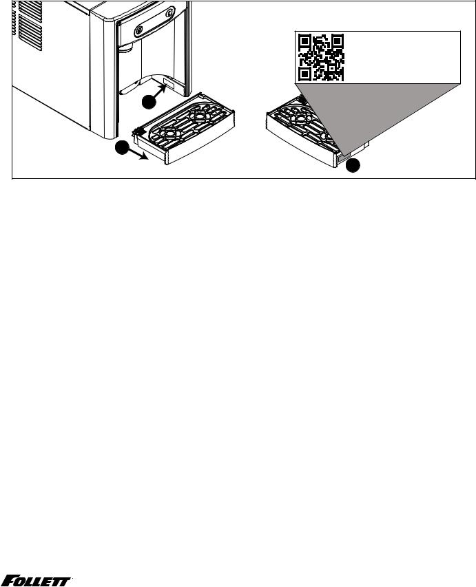
After uncrating and removing all packing material, inspect the equipment for concealed shipping damage.. If damage is found, immediately notify the shipper and contact Follett Corporation so that we can help in the filing of a claim, if necessary.. If needed, the serial number of your dispenser can be found by removing the drip tray and locating the serial number label .. A QR Code is located on the right hand side of the drip tray .. This code allows you to access manuals, technical bulletins, and on- line training related to the 7 Series and 15 Series dispensers..
Scan to access technical documentation or visit
www.follettice.com/7and15seriesdocs
00981100R01
2
1
3
Check your paperwork to verify that you received the correct dispenser.. Follett configuration numbers are designed to provide information about the type of dispenser you are receiving.. The following is an explanation of the different model numbers..
|
|
7 |
|
|
CI |
|
100 |
|
|
A |
|
|
|
|
|||||
|
|
|
|
|
|
|
|
|
|
|
|
|
|
|
|
|
|
|
|
|
|
|
|
|
|
|
|
|
|
|
|
|
|
|
|
|
|
|
|
|
|
|
|
|
|
|
|
|
|
|
|
|
|
|
|
|
|
|
|
|
|
|
|
|
|
|
|
|
|
|
|
|
|
|
|
|
|
|
|
Dispenser Storage |
|
|
Configuration |
|
|
Icemaker Capacity |
|
Condenser |
|||||||||||
Capacity |
|
|
|
|
|
||||||||||||||
|
|
|
|
|
|
|
|
|
|
|
|
|
|
|
|
|
|||
|
|
|
|
|
|
|
|
|
|
|
|
|
|||||||
7 lb (3..1 kg) |
CI |
Countertop |
100 |
lbs (45..3 kg) per day |
A |
Air-cooled |
|||||||||||||
15 lb (6..8 kg) |
FS |
Freestanding |
|||||||||||||||||
|
|
|
|
|
|
|
|
|
|
||||||||||
|
|
|
|
|
|
|
|
|
|
|
|
|
|
|
|
|
|
|
|
Carbonator Installation Kit Contents
Please confirm the contents of your Carbonator Installation kit:
1 – CO2 regulator
15 ft – ¼" OD tubing
1 – Carbonator cradle bracket
1 – Carbonator power cord
1 – ¼" sparkling water tube assembly
1 – 3/8" chilled still water tube assembly
2 – Carbonator front brackets
1 – ¼" plug fitting
1 – ¼" tee fitting 8" rubber edging
1 – ShokBlok water pressure regulator
5 – 10-32 self tapping screws
1 – Water Block kit includes:
1 – Water Block flood prevention device
1 – Water Block mounting bracket
2 – ¼" tube x ¾" GHT fittings
1 – ¾" GHT x ¾" GHT fitting
1 – 8-32 self tapping screw
Sparkling Ice and Water Dispenser 7CI100A/7FS100A, 15CI100A/15FS100A |
5 |

Important Safety Information––––––––––––––––––––––––––––––––––––––––––
Please read and adhere to the following safety information while installing, using, or servicing your Follett Ice Dispenser..
1.Always disconnect power before servicing the dispenser..
2.Ice is slippery.. Maintain counters and floors around dispenser in a clean and ice-free condition..
3.Ice is food.. Follow the recommended cleaning and sanitizing instructions to maintain cleanliness of delivered ice..
Specifications– –––––––––––––––––––––––––––––––––––––––––––––––––––––
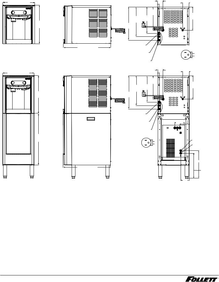
Dispenser Dimensions
|
7CI100A |
7FS100A |
15CI100A |
15FS100A |
Width |
14..50" (40 cm) |
14..50" (36..8 cm) |
14..50" (40 cm) |
14..50" (40 cm) |
|
|
|
|
|
Depth |
22..12" (56..2 cm) |
22..12" (56..2 cm) |
23..50" (59..7 cm) |
23..50" (59..7 cm) |
|
|
|
|
|
Height |
17..50" (44..5 cm) |
41..88" (106..4 cm) |
22..50" (57..2 cm) |
46..75" (118..7 cm) |
|
|
|
|
|
Unit Shipping Weight |
90 lb (41 kg) |
120 lb (54..4 kg) |
100 lb (45..4 kg) |
130 lb (60 kg) |
|
|
|
|
|
Carbonator Dimensions
Width |
10..25" (26..01 cm) |
|
|
Depth |
16..38" (41..6 cm) |
|
|
Height |
16..38" (41..6 cm) |
|
|
Unit Shipping Weight |
58..5 (26..5 kg) |
|
|
Ambient Information
 CAUTION!
The 7CI100A/7FS100A and 15CI100A/15FS100A are for indoor use only. Designed for commercial use. Follett is not able to provide in-house services for residential installations.
|
Maximum* |
|
|
Minimum* |
|
|
|
|
|
Air Temperature† |
100 F (38 C) |
|
50 |
F (10 C) |
Water Temperature |
90 F (32..2 C) |
|
40 |
F (4..5 C) |
|
|
|
|
|
Water Pressure |
70 psi (483 kpa) |
|
10 psi (69 kpa) |
|
|
|
|
|
|
Relative Humidity |
|
55% at 78 F (25..5 C) |
||
|
|
|
|
|
* Use outside of these limitations is misuse and will void warranty..
† Best performance is achieved between 80 F (27 C) and 50 F (10 C)..
Plumbing
§§ Water Inlet: 1/4" OD push-to-connect
§§ Optional Drain Accessory Kit (item# 00956375 or 00981977): 1/2" ID tubing §§ Water shut-off recommended within 5 ft.. (1..5 m) of dispenser
6 Sparkling Ice and Water Dispenser 7CI100A/7FS100A, 15CI100A/15FS100A

Specifications– –––––––––––––––––––––––––––––––––––––––––––––––––––––
Water


 WARNING!
Connect to potable water supply only.
§§ Water Mineral Content:
––TDS: greater than 80 ppm (mg/l) but less than 400 ppm (mg/l)
––Hardness: Less than 200 mg/l (12 gpg)
§§ Not recommended for use with softened water
Clearances
§§ 3" (77 mm) behind and on each side of dispenser for electrical and connection and ventilation §§ 4" (101..6 mm) around chiller/carbonator
Electrical
§§ 115V, 60 Hz, 1 phase, 6..5A, maximum fuse 15A §§ Connect to dedicated 15A circuit, fuse or breaker
§§ Must be grounded - requires 3-prong outlet.. Do not remove ground..
Refrigeration


 WARNING!
Do not damage the refrigerant circuit. Refrigerant can cause personal injury and/or damage dispenser.
Refrigerant R134a
§§ Dispenser: 7..6 ounces (215 grams)
§§ Chiller/Carbonator: 1..94 ounces (55 grams)
Heat Rejection
§§ 1700 BTU/hr (498 W) - dispenser
§§ 450 BTU/hr (132 W) - chiller/carbonator
Chiller/Carbonator Detailed Drawing
|
10.25" |
|
(26 cm) |
POWER |
T-STAT |
SWITCH |
|
IEC |
|
POWER CORD |
|
CONNECTION |
|
16.38" |
|
(41.6 cm) |
|
10.00" |
|
(25.4 cm) |
|
7.69" |
|
(19.5 cm) |
|
|
1.75" (4.4 cm) |
SPARKLING |
4.50" |
2.19" (5.6 cm) |
|
WATER OUT |
(11.4 cm) |
|
STILL |
1/4” PUSH- |
|
||
|
|
||
TO-CONNECT |
|
|
WATER OUT |
|
|
|
1/4” PUSH- |
|
|
|
TO-CONNECT |
|
|
|
15.06" |
|
|
|
(38.3 cm) |
|
|
|
WATER |
|
|
|
INLET |
|
|
|
1/4” PUSH- |
|
|
|
TO-CONNECT |
|
|
|
CO2 GAS |
|
|
|
1/4” PUSH- |
|
|
|
TO-CONNECT |
|
|
|
4.50" |
|
|
3.31" |
(11.4 cm) |
|
|
(8.4 cm) |
|
|
|
1.75" (4.4 cm) |
|
ALL CARFBONATOR CONNECTIONS ARE 1/4" PUSH TO CONNECT
Sparkling Ice and Water Dispenser 7CI100A/7FS100A, 15CI100A/15FS100A |
7 |
Specifications (continued)– ––––––––––––––––––––––––––––––––––––––––––––––
7 Series Detailed Drawing
Countertop models
14.50" (36.8 cm)
17.50" (44.5 cm)
|
|
0.69" (17.5 mm) |
2.38" (6 cm) |
2.94" (7.5 cm) |
|
|
|
|
|
|
|
10.75" |
|
|
|
|
(27.3 cm) |
|
10.81" |
|
13.75" |
12.25" |
|
|
|
|
(27.5 cm) |
||
|
(34.9 cm) |
(31.1 cm) |
|
|
|
15.38" |
|
|
|
|
(39.1 cm) |
|
|
|
|
CHILLER/CARBONATOR |
|
|
|
22.12" (56.2 cm) |
POWER CORD CONNECTION |
NEMA 5-15 |
|
|
|
|
|
||
|
SPARKLING WATER INLET |
|
||
|
right angle |
L2 |
||
|
1/4" PUSH TO CONNECT |
|
G |
|
|
STILL WATER INLET 3/8" |
|
L1 |
|
|
|
|
||
|
PUSH TO CONNECT |
|
|
|
Freestanding models
14.50" (36.8 cm)
17.50" (44.5 cm)
24.38" (61.9 cm)
|
0.69" (17.5 mm) |
2.38" (6 cm) |
2.94" (7.5 cm) |
|
|
|
|
|
10.75" |
|
|
|
(27.3 cm) |
|
10.81" |
13.75" |
12.25" |
|
|
|
(27.5 cm) |
||
(34.9 cm) |
(31.1 cm) |
|
|
15.38" |
|
|
|
(39.1 cm) |
|
|
|
CHILLER/CARBONATOR |
|
|
|
POWER CORD CONNECTION |
|
|
|
SPARKLING WATER INLET |
4.50" (11.4 cm) |
||
1/4" PUSH TO CONNECT |
|
2.19" (5.6 cm) |
|
STILL WATER INLET 3/8" |
|
|
|
PUSH TO CONNECT |
|
|
|
NEMA 5-15 |
|
|
WATER INLET 1/4" |
|
|
PUSH TO CONNECT |
|
right angle |
L2 |
|
|
|
|
||
|
G |
|
|
|
L1 |
|
CO2 INLET 1/4" PUSH |
|
|
|
TO CONNECT |
|
|
|
12.75" (32.3 cm) |
22.12" (56.2 cm) |
|
|
11.56" (29.4) |
|
|
|
|
|
|
|
3.94" |
|
|
|
(10.0 cm) |
8 Sparkling Ice and Water Dispenser 7CI100A/7FS100A, 15CI100A/15FS100A

Specifications (continued)– ––––––––––––––––––––––––––––––––––––––––––––––
15 Series Detailed Drawing
Countertop models |
14.50" (36.8 cm) |
22.50" |
(57.2 cm) |
23.50" (59.7 cm) |
22.12" (56.2 cm) |
Freestanding models |
14.50" (36.8 cm) |
22.38" |
(56.8 cm) |
46.75" |
(118.7 cm) |
24.38" |
(61.9 cm) |
23.50" (59.7 cm) |
22.12" (56.2 cm) |
2.38" (6 cm) |
2.94" (7.5 cm) |
0.69" (17.5 mm) |
|
15.63" |
15.69" |
(39.2 cm) |
|
17.53" |
(39.9 cm) |
|
|
(43.5 cm) |
|
18.63" |
|
(47.3 cm) |
|
20.25" |
|
(51.4 cm) |
|
CHILLER/CARBONATOR |
|
POWER CORD CONNECTION |
|
SPARKLING WATER INLET |
NEMA 5-15 |
L2 |
|
right angle |
G |
||
1/4" PUSH TO CONNECT |
|
L1 |
|
STILL WATER INLET 3/8" |
|
|
|
PUSH TO CONNECT |
|
|
|
2.38" (6 cm) |
2.94" (7.5 cm) |
0.69" (17.5 mm) |
|
15.63" |
15.69" |
(39.2 cm) |
|
17.53" |
(39.9 cm) |
|
|
(43.5 cm) |
|
18.63" |
|
(47.3 cm) |
|
20.25" |
|
(51.4 cm) |
|
CHILLER/CARBONATOR |
|
POWER CORD CONNECTION |
|
SPARKLING WATER INLET |
4.50" (11.4 cm) |
|
1/4" PUSH TO CONNECT |
||
2.19" (5.6 cm) |
||
|
||
STILL WATER INLET 3/8" |
|
|
PUSH TO CONNECT |
|
|
NEMA 5-15 |
WATER INLET 1/4" |
|
PUSH TO CONNECT |
||
right angle L2 |
||
G |
|
|
L1 |
CO2 INLET 1/4" PUSH |
|
|
TO CONNECT |
|
|
12.75" (32.3 cm) |
|
|
11.56" (29.4) |
|
|
3.94" |
|
|
(10.0 cm) |
Sparkling Ice and Water Dispenser 7CI100A/7FS100A, 15CI100A/15FS100A |
9 |

Installation–––––––––––––––––––––––––––––––––––––––––––––––––––––––––
 CAUTION!
No service or maintenance should be performed until the technician has thoroughly read this service manual. Except for routine cleaning and sanitizing, only qualified technicians should attempt to service or maintain this equipment.
Countertop Installation |
Fig.. 1 |
|
The 7 Series countertop model is designed to fit on counters underneath |
countertop models |
|
standard mounted cabinets, this does not apply to 15 Series models or |
||
|
||
any model using optional leg accessory.. See page 6 for dimensions.. |
minimum 3" (77 mm) |
|
Installation instructions for freestanding model may be found on page 12.. |
clearance required |
|
|
||
1. A clearance of at least 3" (77 mm) is required behind and on |
|
|
each side of the dispenser for electrical connection and ventilation |
|
|
(Fig.. 1).. |
|
2. Position dispenser in desired final location and trace opening for countertop cutout (right-side panel must be removed) or use Fig.. 2 to locate cutout..
3.Use appropriate tool to make cutout..
Fig.. 2
REQUIRED CLEARANCE |
|
1.76" (4.5 cm) |
3" (7.6 cm) |
|
|
|
1.81" |
|
(4.6 cm) |
|
cm)28.8(21 " |
10 Sparkling Ice and Water Dispenser 7CI100A/7FS100A, 15CI100A/15FS100A
4.Position chiller/carbonator in cabinet (allow for required clearances, 4" on sides and back) and mark for toe-kick recess cutout (Fig.. 3)..
5.Use appropriate tool to make toe-kick recess cutout..
6.Rough-in the electrical service and water line(s)..
§§ Electrical: 115V, single phase, 15A receptacle required.. The dispenser has an integral 8 ft.. (2..4 m) cord and plug.. The chiller/carbonator connects to the dispenser via a supplied 6 ft.. power cord..
§§ Water: supply line (with shut-off valve) connects to the dispenser's 1/4" NPT male inlet.. A tee fitting can be employed to supply both the dispenser and chiller/carbonator from a single shut-off valve.. Alternatively, a second supply line (with shut-off valve) can be installed within the cabinet for the chiller/carbonator's 1/4" push-to-connect inlet..
NOTICE!
If installing optional Drip Tray Drain Kit or Leg Accessory, complete those steps before proceeding. Refer to instructions included with the Drip Tray Drain Kit, or see page 12 for Leg Accessory instructions.
Fig.. 3
CUTOUT FOR DISPENSER
COUNTERTOP
1.47"
VENTILATION CUTOUT TO BE |
5.13" |
PLACED OVER KICK RECESS AND
ALIGNED WITH VENT SHROUD
7.Place chiller/carbonator unit on floor in front of dispenser..
8.Follow the Final Connections instructions for countertop models that follows..
Sparkling Ice and Water Dispenser 7CI100A/7FS100A, 15CI100A/15FS100A |
11 |
Installation (continued) –––––––––––––––––––––––––––––––––––––––––––––––––
Optional Leg Accessory Installation |
Fig.. 4 |
 CAUTION!
Use caution when tipping the dispenser during leg installation. Do not lay unit on back or side. DO NOT EXCEED 30° angle. Tipping more than 30° can result in compressor malfunction.
1.If installing optional 4" Leg Accessory (item# 00956300), place a 5" (127 mm) spacer underneath the dispenser to ease installation..
2.Remove four plastic, thread-protecting plugs from bottom of dispenser..
3.Screw each leg into chassis (Fig.. 4)..
5" (127 mm) |
spacer |
min. |
|
Freestanding Installation |
Fig.. 5 |
|
Installation instructions for countertop model may be found on Countertop |
freestanding models |
|
Installation on page 10. |
||
|
||
1. A clearance of at least 3" (77 mm) is required behind and on |
minimum 3" (77 mm) |
|
clearance required |
||
each side of the dispenser for electrical connection and ventilation |
|
|
(Fig.. 5).. |
|
2. Rough-in the electrical service and water line(s)..
§§ Electrical: 115V, single phase, 15A receptacle required.. The dispenser has an integral 8 ft.. (2..4 m) cord and plug.. The chiller/carbonator connects to the dispenser via a supplied power cord..
§§ Water: supply line (with shut-off valve) connects to 1/4" push-to- connect Tee that splits the supply to the dispenser and chiller/ carbonator (also 1/4" push-to-connect)..
12 Sparkling Ice and Water Dispenser 7CI100A/7FS100A, 15CI100A/15FS100A

1. To install 6" Leg Accessory (item# 00956318), tilt or lay base stand |
Fig.. 6 |
|||||||||
on side and screw each leg into stand (Fig.. 6).. |
|
|
|
|
|
|
|
|
|
|
|
|
|
|
|
|
|
|
|
|
|
|
|
|
|
|
|
|
|
|
|
|
|
|
|
|
|
|
|
|
|
|
|
|
|
|
|
|
|
|
|
|
|
|
|
|
|
|
|
|
|
|
|
|
|
|
|
|
|
|
|
|
|
|
|
|
|
|
|
|
|
|
|
|
|
|
|
|
|
|
|
|
|
|
|
|
|
|
|
|
|
|
|
|
|
|
|
|
|
|
|
|
|
|
|
|
|
|
|
|
2. |
Remove four plastic, thread-protecting plugs from bottom of |
Fig.. 7 |
|
dispenser.. |
|
3. |
Attach dispenser to base stand with supplied hardware (Fig.. 7).. |
|
NOTICE! |
|
|
|
If installing optional Drip Tray Drain Kit, refer to instructions |
|
|
included with the Drip Tray Drain Kit. |
|
4. |
Place chiller/carbonator unit on floor in front of dispenser.. |
|
5. |
Follow the Final Connections instructions for countertop models that |
|
|
follows.. |
|
|
|
X4 |
Sparkling Ice and Water Dispenser 7CI100A/7FS100A, 15CI100A/15FS100A |
13 |

Final Connections - Countertop Installation
1.Use 1/4" OD tubing to plumb incoming water (above countertop) to the fitting on the rear of the dispenser
(Fig.. 8..1)..
2.Mount the Flood Prevention Valve bracket inside the cabinet.. Refer to the instructions included with the Flood Prevention Valve and set the Valve to the "2" position using the included key..
3.Use 1/4" OD tubing to plumb incoming water (below countertop) to the Flood Prevention Valve, assuring the correct length so that it snaps into the mounting bracket (note proper flow direction) (Fig.. 8..2)..
4.Plumb to the Water Pressure Regulator (Fig.. 8..3)..
5.Then plumb to the Chiller/Carbonator (Fig.. 8..4) assuring there is enough line that the Chiller/Carbonator can be removed and set in front of the cabinet.. Note proper flow direction for the devices and the Flood Prevention Valve must be mounted vertically..
6.Remove the right side panel of the dispenser (see Page 24) to expose the Chiller/Carbonator connections..
7.Install the insulated Sparkling and Chilled Still water lines and the power cord to the dispenser, routing the lines down through the cutout in the countertop (Fig.. 8..5)..
Note: Water lines are supplied at 6 ft.. lengths.. Note the Chilled Still water is 3/8" OD tubing and the Sparkling water is 1/4" OD tubing..
8.Install the plug in the center Ambient Water Out of the Chiller/Carbonator (Fig.. 8..6)..
9.Connect the Chilled Still water 3/8" OD tubing to the Chiller/Carbonator (Fig.. 8..7)..
10.Connect the Sparkling water 1/4" OD tubing to the Chiller/Carbonator (Fig.. 8..8)..
11.Install the tube fitting and flare washer onto the CO2 regulator.. Install the CO2 pressure regulator onto the CO2 tank.. Make sure that the CO2 tank is installed in a location with appropriate tipping prevention
according to local codes.. Installing an OSHA approved cylinder rack with chain in an adjacent cabinet with easy access for cylinder change-outs is recommended..
12.Install 1/4" OD LLDPE tubing from the regulator to the back of the Chiller/Carbonator (Fig.. 8..9)..
13.Leave the shutoff valve in the OFF position and open the cylinder valve.. Using a flat blade screwdriver adjust the CO2 pressure to 60 psi on the top gauge.. (The CO2 cylinder is not supplied and is the responsibility of the customer..)
14.Turn on water and leave CO2 off.. Make sure all water valves are open and check for leaks..
15.Plug in the dispenser but do not turn Chiller/Carbonator on at this point..
16.Dispense 1 liter Still water from the dispenser, then dispense 1 liter Sparkling water (Note: at this point, the water will not be carbonated)..
17.Remove the screw from the Chiller/Carbonator top panel (Fig.. 8..10) and remove top panel (Fig.. 8..11)..
18.Pull the Chiller/Carbonator safety valve ring (Fig.. 8..12) until water starts to come out of the side of the fitting and release immediately.. It may take up to a minute for water to run from the safety valve.. Reinstall Chiller/Carbonator top panel..
Note: This procedure is required to remove an air bubble upon initial installation which can prevent the machine from functioning properly.. If air is trapped, the carbonation pump will continue running and eventually fault.. This requires a power cycle to reset..
19.Open the CO2 valve on the CO2 regulator and turn ON the power switch on the front of the Chiller/ Carbonator.. Make sure the thermostat on the front of the Chiller/Carbonator is set to the coldest position
(7).. Dispense Sparkling water until you hear the Chiller/Carbonator pump turn on (Note: the pump is very quiet).. The pump should turn off again within a few seconds depending on how much carbonated water is dispensed.. Perform at least 3 dispenses to cycle the pump and assure there is no trapped air in the system..
20.Install Chiller/Carbonator cradle into cabinet.. Slide Chiller/Carbonator into cabinet between the cradle opening and assure the Chiller/Carbonator exhaust shroud is located above the cutout in the toe-kick recess.. Allow 2-4 hours for the Chiller/Carbonator to reach temperature..
14 Sparkling Ice and Water Dispenser 7CI100A/7FS100A, 15CI100A/15FS100A

Fig.. 8
|
|
|
INCOMING |
|
|
|
|
|
|
WATER (above counter, |
|
||
|
|
|
for ice production) |
|
||
|
|
|
1 |
|
INCOMING |
|
|
|
|
|
|
|
|
|
|
|
|
|
WATER (below counter, |
|
|
|
|
5 |
|
for chilled and sparkling |
|
|
|
|
|
2 |
water) |
|
|
|
5 |
FLOOD |
|
|
|
|
|
|
CO2 REGULATOR |
|
||
|
|
|
PREVENTION |
|
||
|
|
|
|
|
|
|
|
|
|
VALVE* |
|
|
|
8 |
6 |
7 |
|
|
|
|
|
|
|
|
|
||
|
|
|
3 |
WATER |
|
|
SPARKLING |
AMBIENT |
CHILLED |
|
PRESSURE |
|
|
|
REGULATOR |
|
||||
OUT |
|
OUT |
|
CO2 |
||
|
|
|
|
|||
|
|
|
|
|
|
|
|
|
|
|
|
|
TANK |
|
11 |
|
|
10 |
12 |
4 |
IN H2O |
|
|
||
* Flood Prevention Valve must be set to “2” and |
9 |
IN CO2 |
|
|
|||
mounted vertically - see instructions included with Valve.
Sparkling water draining procedure
1.Turn off carbonator power and incoming water..
2.Dispense all Sparkling Water until only CO2 comes out (approx.. 32 oz..)
3.Turn off CO2 and dispense from Sparkling button to evacuate remaining CO2..
4.Disconnect water, CO2 and power from carbonator..
Sparkling Ice and Water Dispenser 7CI100A/7FS100A, 15CI100A/15FS100A |
15 |

Final Connections - Freestanding Installation
1.Mount the Flood Prevention Valve bracket to the rear of the base stand (Fig.. 9..1)..
2.Refer to the instructions included with the Flood Prevention Valve and set the Valve to the "2" position using the included key..
3.Use 1/4" OD tubing to plumb incoming water to the tee fitting (Fig.. 9..2)..
4.Use 1/4" OD tubing to plumb from the tee fitting to the fitting on the rear of the dispenser (Fig.. 9..3)..
5.Use 1/4" OD tubing to plumb from the tee to the Flood Prevention Valve, assuring the correct length so that it snaps into the mounting bracket (note proper flow direction) (Fig.. 9..4)..
6.Use 1/4" OD tubing to plumb to the Water Pressure Regulator (Fig.. 9..5)..
7.Then plumb to the Chiller/Carbonator (Fig.. 9..6) assuring there is enough line that the Chiller/Carbonator can be removed and set in front of the base stand..
8.Remove the right side panel of the dispenser (see Page 24) to expose the Chiller/Carbonator connections.. Cut a 1..25" length of the rubber edging.. Install the 1..25" length on the short edge of the base stand pass through (Fig.. 9..7) and the remaining 6..75" length on the long edge (Fig.. 9..8)..
9.Install the insulated Sparkling and Chilled Still water lines and the power cord to the dispenser, routing the lines down through the base stand (Fig.. 9..9)..
Note: Water lines are supplied at 6 ft.. lengths, but can be trimmed to 4 ft.. length for freestanding applications.. Note the Chilled Still water is 3/8" OD tubing and the Sparkling water is 1/4" OD tubing..
10.Install the plug in the center Ambient Water Out of the Chiller/Carbonator (Fig.. 9..10)..
11.Connect the Chilled Still water 3/8" OD tubing to the Chiller/Carbonator (Fig.. 9..11)..
12.Connect the Sparkling water 1/4" OD tubing to the Chiller/Carbonator (Fig.. 9..12)..
13.Install the tube fitting and flare washer onto the CO2 regulator.. Install the CO2 pressure regulator onto the CO2 tank.. Make sure that the CO2 tank is installed in a location with appropriate tipping prevention
according to local codes.. Installing an OSHA approved cylinder rack with chain in an adjacent cabinet with easy access for cylinder change-outs is recommended..
14.Install 1/4" OD LLDPE tubing from the regulator to the back of the Chiller/Carbonator (Fig.. 9..13)..
15.Leave the shutoff valve in the OFF position and open the cylinder valve.. Using a flat blade screwdriver adjust the CO2 pressure to 60 psi on the top gauge.. (The CO2 cylinder is not supplied and is the responsibility of the customer..)
16.Turn on water and leave CO2 off.. Make sure all water valves are open and check for leaks..
17.Plug in the dispenser but do not turn Chiller/Carbonator on at this point..
18.Dispense 1 liter Still water from the dispenser, then dispense 1 liter Sparkling water (Note: at this point, the water will not be carbonated)..
19.Remove the screw from the Chiller/Carbonator top panel (Fig.. 9..14) and remove top panel (Fig.. 9..15)..
20.Pull the Chiller/Carbonator safety valve ring (Fig.. 9..16) until water starts to come out of the side of the fitting and release immediately.. It may take up to a minute for water to run from the safety valve.. Reinstall Chiller/Carbonator top panel..
Note: This procedure is required to remove an air bubble upon initial installation which can prevent the machine from functioning properly.. If air is trapped, the carbonation pump will continue running and eventually fault.. This requires a power cycle to reset..
21.Open the CO2 valve on the CO2 regulator and turn ON the power switch on the front of the Chiller/ Carbonator.. Make sure the thermostat on the front of the Chiller/Carbonator is set to the coldest position
(7).. Dispense Sparkling water until you hear the Chiller/Carbonator pump turn on (Note: the pump is very quiet).. The pump should turn off again within a few seconds depending on how much carbonated water is dispensed.. Perform at least 3 dispenses to cycle the pump and assure there is no trapped air in the system..
22.Install Chiller/Carbonator cradle into base stand.. Slide Chiller/Carbonator into base stand between the cradle opening and assure the Chiller/Carbonator exhaust shroud is located above the cutout in the base stand.. Install the front Chiller/Carbonator retaining brackets into the base stand and replace the base stand cover.. Allow 2-4 hours for the Chiller/Carbonator to reach temperature..
16 Sparkling Ice and Water Dispenser 7CI100A/7FS100A, 15CI100A/15FS100A

Fig.. 9
|
|
|
INCOMING |
|
|
|
|
WATER |
|
|
|
3 |
2 |
CO2 REGULATOR |
|
|
9 |
4 |
|
|
|
|
|
|
|
|
9 |
FLOOD |
|
|
|
|
|
|
|
|
PREVENTION |
|
|
|
|
|
VALVE* |
|
|
|
|
|
CO2 |
12 |
10 |
11 |
|
TANK |
|
|
|||
|
|
|
||
|
|
|
5 |
WATER |
|
|
|
|
|
SPARKLING |
AMBIENT |
CHILLED |
|
PRESSURE |
|
REGULATOR |
|||
OUT |
|
OUT |
|
|
15 |
6 |
IN H2O |
|
||
14 |
16 |
|
|
|
IN CO2 |
|
13 |
1 |
|
|
|
|
1.25" length |
|
|
7 |
|
|
8 |
* Flood Prevention Valve must be set to “2” and |
|
|
|
|
6.75" length |
mounted vertically - see instructions included |
|
with Valve. |
|
|
|
Sparkling water draining procedure
1.Turn off carbonator power and incoming water..
2.Dispense all Sparkling Water until only CO2 comes out (approx.. 32 oz..)
3.Turn off CO2 and dispense from Sparkling button to evacuate remaining CO2..
4.Disconnect water, CO2 and power from carbonator..
Sparkling Ice and Water Dispenser 7CI100A/7FS100A, 15CI100A/15FS100A |
17 |

Installation (continued) ––––––––––––––––––––––––––––––––––––––––––––––––––––––––––––––––––––––
5. Secure unit to wall or cove molding with supplied bracket (Fig.. 10) to |
Fig.. 10 |
|||||||
prevent tipping.. |
|
|
|
|
|
|
|
|
|
|
|
|
|
|
|
|
|
|
|
|
|
|
|
|
|
|
|
|
|
|
|
|
|
|
|
Note: Fasteners must be supplied by installer..
WARNING!
Freestanding unit must be secured to wall to prevent tipping. Failure to do could result in personal injury or damage to the unit.
18 Sparkling Ice and Water Dispenser 7CI100A/7FS100A, 15CI100A/15FS100A
 Loading...