


REF 20/25 – LB REF 20/25 – PH REF 20/25 – BB
Order parts online www.follettice.com
Installation, Operation and Service Manual
Following installation, please forward this manual to the appropriate operations person.
801 Church Lane • Easton, PA 18040, USA |
|
Toll free (877) 612-5086 • +1 (610) 252-7301 |
|
www.follettice.com |
00926170R09 |

Contents
Welcome to Follett. . . . . . . . . . . . . . . . . . . . . 3
Before you begin. . . . . . . . . . . . . |
3 |
Ambients. . . . . . . . . . . . . . . . |
4 |
Clearances . . . . . . . . . . . . . . . |
4 |
Electrical specifications . . . . . . . . . . . |
4 |
Refrigeration specifications . . . . . . . . . |
. 4 |
Detail drawing. . . . . . . . . . . . . . . |
4 |
Installation. . . . . . . . . . . . . . 5
Adjust self-closing door (if necessary). . |
. . . |
. 5 |
Install shelves (if equipped) and power up |
. . . |
5 |
Fill product bottle. . . . . . . . . . . . . . . . . . . . |
. . . . . . |
. 6 |
Remote alarm connections (if desired) . . . . . |
7 |
|
Dry contacts. . . . . . . . . . . . . . |
7 |
|
RS-485 port. . . . . . . . . . . . . . |
7 |
|
Operation . . . . . . . . . . . . . |
. |
8 |
||
Quick setup checklist. . . . . . . . . . . |
. |
8 |
||
Interior LED lights.. . . . . . . . . . . . |
. |
8 |
||
Set time & date.. . . . . . . . . . . . . |
. |
8 |
||
Change temperature display to show degrees |
|
|
||
Fahrenheit (if desired). . . . . . . . . . . |
|
|
9 |
|
High and low alarm setup. . . . . . . . . . |
|
|
10 |
|
Alarms. . . . . . . . . . . |
. . . . . . |
|
|
12 |
Alarm muting . . . . . . . . . . . . . . . 12 |
||||
Alarm volume selection. . . . . . . . . . |
. |
13 |
||
Alarm silence. . . . . . . . . . . . . . . 13 |
||||
Password PIN security (default is 3843). . . . |
|
14 |
||
To turn password on/off. . . . . . . . . . |
. |
14 |
||
To make a new password PIN. . . . . . . . |
|
15 |
||
Min/max temperature logging.. . . . . . . . |
|
16 |
||
Probe calibration.. . . . . . . . . . . . . |
|
17 |
||
Chart recorder set up (if so equipped). . |
. . . |
|
18 |
|
Chart recorder calibration.. . . . . . . . . |
|
18 |
||
Changing the chart paper. . . . . . . . . |
|
|
18 |
|
Replacing the pen. . |
. . . . . . . . . . |
|
|
18 |
Removing drawers. . . . . . . . . . . . . 19 |
||||
Removing slides. . |
. . . . . . . . . . . |
. |
19 |
|
Cleaning. . . . . . . . . . . . . . . 20
Interior cleaning. . . . . . . . . . . . . . 20 Exterior cleaning. . . . . . . . . . . . . 20
Annual cleaning. . . . . . . . . . . . . . 21
Service. . . . . . . . . . . . . . . 22
Refrigeration system.. . . . . . . . . . . 22
Defrosting . . . . . . . . . . . . . . . . 22 Controller operation . . . . . . . . . . . . 23 Temperature sensor readings. . . . . . . . 23 Heated door (option) – changing cycle . . . . . 24 Controller hot key. . . . . . . . . . . . . 27
Hot key upload. . . . . . . . . . . . . . 27 Hot key download. . . . . . . . . . . . . 28
Troubleshooting . . . . . . . . . . . 34
Before calling for service. . . . . . . . . . 34
Appendix. . . . . . . . . . . . . . 35
Control key functions. . . . . . . . . . . . 35 Menu Navigation table. . . . . . . . . . . 35
Replacement parts. . . . . . . . . . 36 |
|
Unit cooler. . . . . . . . . . . . . . . |
36 |
Cabinet. . . . . . . . . . . . . . . . . |
37 |
Facade. . . . . . . . . . . . . . . . . |
38 |
Door assembly. . . . . . . . . . . . . . |
39 |
2
Welcome to Follett
Follett equipment enjoys a well-deserved reputation for excellent performance, long-term reliability and outstanding after-the-sale support.To ensure that this product delivers that same degree of service, we ask that you take a moment to review this manual before beginning the installation. Should you have any questions or require technical help at any point, please call our technical service group at (877) 612-5086 or +1 (610) 252-7301.
Before you begin
After uncrating and removing all packing material, inspect the equipment for concealed shipping damage. If damage is found, notify the shipper immediately and contact Follett Corporation so that we can help in the filing of a claim, if necessary.
Check your paperwork to determine which configuration you have. Follett configuration numbers are designed to provide information about the type of refrigerator you are receiving. Following is an explanation of the different item numbers.
Model
Cubic foot capacity – 20, 25
Configuration – LB (Laboratory - shelves), PH (Pharmacy - baskets),
BB (Blood bank - drawers)
Door hinge – R (Right hand), L (Left hand)
Door heater option – 00 (No door heater), HT (door heater)
Chart recorder option – 00 (No chart recorder), CR (Chart recorder)
REF 20 LB R 00 00
Specifications
|
REF20-LB |
REF25-LB |
REF20-PH |
REF25-PH |
REF20-BB |
REF25-BB |
Capacity |
19.7 cu ft |
24.6 cu ft |
19.7 cu ft |
24.6 cu ft |
19.7 cu ft |
24.6 cu ft |
|
(558 L) |
(697 L) |
(558 L) |
(697 L) |
(558 L)/ 280 |
(697 L)/ 360 |
|
|
|
|
|
bags (450ml) |
bags (450ml) |
|
|
|
|
|
|
|
Storage |
(4) epoxy- |
(4) epoxy- |
(6) epoxy- |
(6) epoxy- |
(6) stainless |
(6) stainless |
system |
coated shelves |
coated shelves |
coated baskets |
coated baskets |
steel drawers |
steel drawers |
|
|
|
|
|
|
|
Exterior |
29.75" (76 cm) |
29.75" (76 cm) |
29.75" (76 cm) |
29.75" (76 cm) |
29.75" (76 cm) |
29.75" (76 cm) |
width |
|
|
|
|
|
|
|
|
|
|
|
|
|
Exterior |
29" (74 cm) |
35" (89 cm) |
29" (74 cm) |
35" (89 cm) |
29" (74 cm) |
35" (89 cm) |
depth |
|
|
|
|
|
|
|
|
|
|
|
|
|
Exterior |
30.5" (78 cm) |
36.5" (93 cm) |
30.5" (78 cm) |
36.5" (93 cm) |
30.5" (78 cm) |
36.5" (93 cm) |
depth with |
|
|
|
|
|
|
handles |
|
|
|
|
|
|
|
|
|
|
|
|
|
Exterior |
79.5" (202 cm) |
79.5" (202 cm) |
79.5" (202 cm) |
79.5" (202 cm) |
79.5" (202 cm) |
79.5" (202 cm) |
height with |
|
|
|
|
|
|
casters |
|
|
|
|
|
|
|
|
|
|
|
|
|
Interior |
24" x 22.5" x 56" |
24" x 28.5" x 56" |
24" x 22.5" x 56" |
24" x 28.5" x 56" |
24" x 22.5" x 56" |
24" x 28.5" x 56" |
dimensions |
(61 cm x 58 cm x 143 cm) |
(61 cm x 73 cm x 143 cm) |
(61 cm x 58 cm x 143 cm) |
(61 cm x 73 cm x 143 cm) |
(61 cm x 58 cm x 143 cm) |
(61 cm x 73 cm x 143 cm) |
(w x h x d) |
|
|
|
|
|
|
|
|
|
|
|
|
|
Crated |
395 (180 kg) |
430 (196 kg) |
450 (205 kg) |
485 (220 kg) |
475 (216 kg) |
525 (239 kg) |
weight |
|
|
|
|
|
|
|
|
|
|
|
|
|
Max. heat |
950 BTU/hr |
1050 BTU/hr |
950 BTU/hr |
1050 BTU/hr |
950 BTU/hr |
1050 BTU/hr |
rejection |
|
|
|
|
|
|
|
|
|
|
|
|
|
00926170 – REF20/25 LB, PH, BB |
Welcome to Follett |
3 |
|
Standard features – all models |
Door |
Dual pane, low-E glass, condensation free to 80 F (27 C) air/60% RH |
|
|
Door handle |
ADA-compliant, full length handle with integral lock |
|
|
Interior/exterior material |
Heavy-duty, corrosion resistant stainless steel |
|
|
Casters |
(4) dual-wheel swiveling casters with toe locks |
|
|
Insulation |
2.75" (7 cm) thick, CFC-free foam insulation throughout |
|
|
Lighting |
(2) full length side LED lights |
|
|
Air circulation system |
Ducted air through 12 back plenum openings with front face return |
|
|
Temperature probe |
Stainless steel RTD (resistance temperature detectors) top, bottom probe standard |
|
on - BB models, available as option on -LB, -PH models, immersible with panel quick- |
|
disconnect |
|
|
Ambients
Intended for indoor use where ambient temperature typically does not exceed 80 F (27 C) and ambient relative humidity does not exceed 60% RH.A heated door is recommended for higher humidity ambients.
Clearances
The top of the refrigerator must have 10 inches (25.4 cm) of clear space above the refrigerator to ensure proper ventilation of the refrigeration system.
The back of the refrigerator should have 1 inch (2.5 cm) of clearance to allow for power cord clearance on unit and an additional 1 inch (2.5 cm) if the unit is to be plugged in directly behind the refrigerator.
Electrical specifications
115V, 60Hz, 1 phase
Running load amps: 8.4 amps without heated door; max 9.7 amps with door heater energized 100% (adjustable).
Full load amps (90% maximum continuous current per UL 471 at 40 C): 10.5 amps Minimum circuit ampacity: 15 amp dedicated circuit
Maximum size of branch circuit overcurrent device: 15 amp dedicated circuit
Refrigeration specifications
Refrigerant R134a, 11.4 oz (322g)
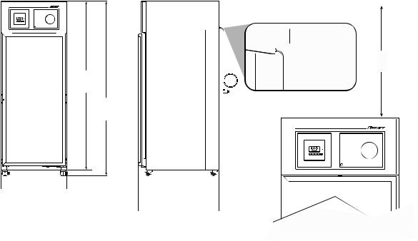
Detail drawing
76.75"
(195cm)
79.5"
(202cm)
29.75"
 (76cm)
 REF20
REF20  30.5" (78cm)
 REF25
REF25  36.5" (93cm)
Required Clearances

 1.0" (2.5 cm) for power cord;
  2.0" (2.5 cm) if outlet directly behind unit
10.0"
(25.4cm)
4 |
Welcome to Follett |
00926170 – REF20/25 LB, PH, BB |
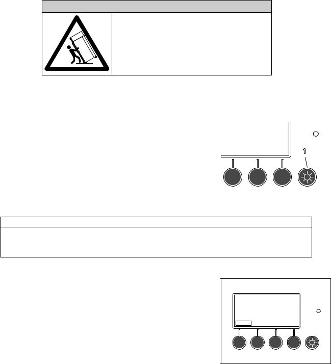
Installation
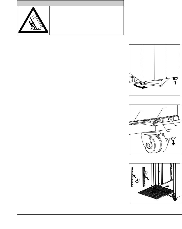
 DANGER
•Do not tilt any unit further than 30° off vertical during uncrating or installation
•Refrigeration module area contains mechanical, moving
parts. Keep hands and arms clear of this area at all times. If access to this area is required, power to unit must be disconnected first.
|
|
Fig. 1 |
|
|
1. |
Remove key taped to side of refrigerator cabinet and unlock door. |
|
|
|
2. |
Remove casters from box packed inside refrigerator. |
|
|
|
|
Note: California facilities requiring wall and floor anchors – refer to wall anchor |
|
|
|
|
kit instructions (#00938241) packed with seismic kit before proceeding with |
|
|
|
|
caster installation. |
|
|
|
3. |
Unbolt refrigerator from pallet. |
|
|
|
4. |
Rotate refrigerator on pallet to install casters (Fig. 1.1). |
|
|
|
5. |
Install casters by hand one at a time using channel locks to tighten, until |
|
|
|
|
caster meets against the bottom of cabinet (Fig. 1.2). |
|
|
|
6. |
Peel protective film from exterior walls of stainless cabinet. |
|
|
2 |
|
1 |
|
||
|
|
|
|
|
Adjust self-closing door |
Fig. 2 |
|
|
|
1. |
Roll refrigerator to desired location and lock as many casters as |
|
2 |
|
|
possible (Fig 2.1). |
|
Hold Open |
|
2. |
If the door appears to be sagging, remove the philips screw (Fig. 2.2) |
|
Bracket |
|
|
|
|
||
|
holding the Hold Open Bracket to the Hinge Bracket to gain access to |
|
|
|
|
the Sag Adjustment Screw (Fig. 2.3).Turn the Sag Adjustment Screw to |
|
|
4 |
|
align the door squarely with the freezer cabinet. When finished, reinstall |
|
|
|
|
|
|
|
|
|
the Hold Open Bracket. |
|
3 |
|
3. |
Check door for closing tension and adjust if necessary.To check closing |
|
|
|
|
tension, open door 1” and turn screw (Fig. 2.4) counterclockwise until |
|
|
1 |
|
you achieve positive close. (Light will go out) Then, turn another half |
|
|
|
|
turn counterclockwise. |
|
|
|
Install shelves (if equipped) and power up |
Fig. 3 |
|
|
|
1. If refrigerator is equipped with shelves, remove bag containing shelf |
|
|
|
|
|
supports and position them in desired locations on each pilaster and |
|
|
|
|
insert shelves (Fig. 3). |
1 |
2 |
|
2. Plug refrigerator into a 115V 60Hz 15 amp dedicated outlet. |
|
|||
|
|
|
||
|
|
|
3 |
|
00926170 – REF20/25 LB, PH, BB |
|
Installation |
5 |
|
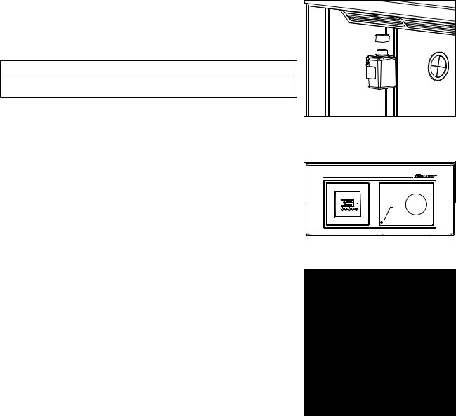
Fill product bottle
1.Remove probe and cap from the top bottle and fill with solution used at your facility (e.g., 50% glycerine and 50% water) (Fig. 4). Replace cap and reinsert probe sensor.
2.If equipped with a bottom probe, perform same procedure for bottom bottle.
ATTENTION INSTALLER
It is imperative that the top probe bottle be filled with a solution that your facility uses to ensure proper operation of unit.
3.Adhere supplied probe wire clips (x4, packaged with manual) to inside wall leading to the probe bottle.
4.Route probe wire into clips and close the clips.
5.Press lower left corner of front facade door to access power switch inside (Fig. 5.1).
6.Press power switch to turn unit on (Fig. 6.1).
7.Install (2) 9V back-up interface batteries (Fig. 6.2) and (1) 9V chart recorder back-up battery (if equipped.)
Fig. 4 |
|
Fig. 5 |
|
|
1 |
Fig. 6 |
|
|
1 |
|
2 |
6 |
Installation |
00926170 – REF20/25 LB, PH, BB |
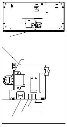
Remote alarm connections (if desired)
Remote communication connections are located on back side of top facade (Fig. 7).
Dry contacts
•Connection to NO or NC contacts provides remote alarming capability
•No temperature data is communicated
RS-485 port
•Connection provides real-time data streaming
–Temperature
–Alarms
–Refrigeration operation
•MODBUS protocol
•Uses 6 pin, 4 conductor RJ11 jack (not supplied)
Fig. 7 |
|
|
|
Hotkey |
|
|
|
Common |
|
|
N/O |
|
|
N/C |
RS485 Port |
Alarm Contacts |
|
|
||
00926170 – REF20/25 LB, PH, BB |
Installation |
7 |
Operation
Quick setup checklist
•Set time/date
•Change temperature display from factory default Celsius to Fahrenheit (if desired)
•Set high/low temperature alarms
•Select password access (if required)
•Setup chart recorder (if equipped)
•Verify solution is in bottle
 DANGER
•Do not extend all of the drawers or baskets when fully loaded to avoid the possibility of the refrigerator tipping forward
•Refrigeration module area contains mechanical, moving
parts. Keep hands and arms clear of this area at all times. If access to this area is required, power to unit must be disconnected first.
|
Fig. 8 |
||
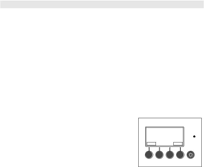
Interior LED lights |
|
|
|
4.0C |
|||
Interior lighting of refrigerator with door closed is controlled by light switch |
|||
|
|
||
(Fig 8.1) on interface. |
Bottom Temp 3.5C |
||
Lights will be on whenever door is open regardless of light switch selection. |
|
1 |
|
|
|||
|
|||
|
|
|
|
ATTENTION
•The time/date are not retained in the event of a power interruption or if the batteries are dead.
•Change batteries with the unit powered up. Change one battery at a time to retain time/date. Failure to follow this procedure will result in loss of time & date and will not provide accurate time and date stamping for high or low temperature alarms.
Fig. 9
Set time & date
Set time and date for stamping of minimum and maximum temperatures. 1. Press Menu button (Fig. 9).
4.0C
Bottom Temp 3.5C Menu
8 |
Operation |
00926170 – REF20/25 LB, PH, BB |
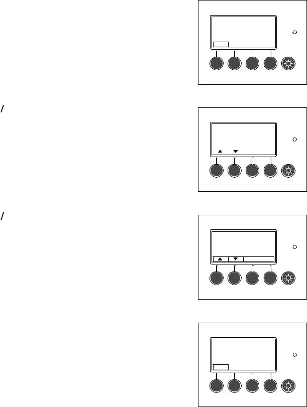
2. Use
 to scroll and highlight Set time/date and press Enter to select (Fig. 10).
3.Adjust the year using
 and press NEXT.
4.Adjust the month using
 and press NEXT.
5.Adjust the day using
 and press NEXT.
6.Adjust the hour using
 and press NEXT. (24 HR Clock)
7.Adjust the minute using
 .
.
8.Press Enter to select values.
9.Press Back until the main temperature display screen is displayed.
Fig. 10
|
Set time/date |
4.0C |
||
|
Set Alar m Volume |
|
||
|
Alar m Silence |
|
||
|
|
|
|
|
|
|
|
Back |
Enter |
Fig. 11
Set year : 2009 |
3.4C |
2009 10/19 16:13
Next  Enter
Enter
Change temperature display to show degrees Fahrenheit (if desired)
Follett has pre-set the temperature display to read in degrees Celsius. If degrees Fahrenheit display is preferred:
1.Press Menu button (Fig. 12).
2.Use
 to scroll and highlight Display Settings and press Enter to select (Fig. 13).
3.Use
 to scroll and highlight Degrees F/C and press Enter to select.
4.Use
 to scroll and highlight F and press Enter to select.
5.Press Back button until the main temperature display screen is displayed.Temperature is displayed in degrees F.
Fig. 12
4.0C
Bottom Temp 3.5C
Menu
Fig. 13
|
Alarm Settings |
4.0C |
|
||
|
Display Settings |
|
|
||
|
Min/Max Temperatures |
|
|
||
|
Batt = 8.5V OK |
|
|
||
|
|
|
|
|
|
|
|
|
Back |
Enter |
|
|
|
|
|
|
|
00926170 – REF20/25 LB, PH, BB |
Operation |
9 |
High and low alarm setup
The high alarm is set to a default of 40 C (104 F) from the factory.This default setting is used so that the alarm will not sound while the unit is pulling down to temperature.The low alarm default setting is 1.0 C (33.8 F).
After the unit has been installed and the system has stabilized (approximately 1 hr), the high and low alarm set points should be adjusted to desired settings.
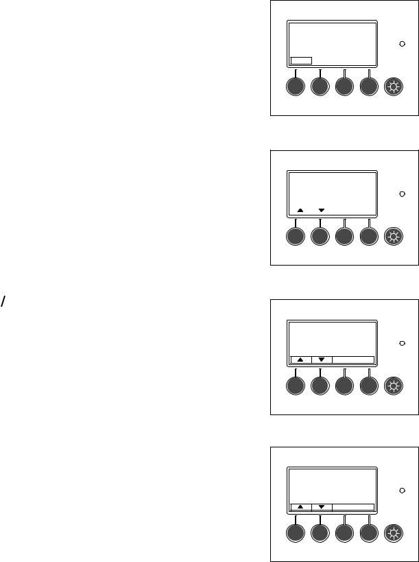
1.Press Menu button (Fig. 14).
2.Alarm Settings will be highlighted. Press Enter to select (Fig. 15).
Fig. 14
4.0C
Bottom Temp 3.5C Menu
Fig. 15
|
Alarm Settings |
4.0C |
||
|
Display Settings |
|
||
|
Min/Max Temperatures |
|
||
|
Batt = 8.5V OK |
|
||
|
|
|
|
|
|
|
|
Back |
Enter |
Fig. 16
3.Use
 to scroll and highlight High Alarm Set and press Enter to select (Fig. 16).
High Alarm Set |
4.0C |
Low Alarm Set |
|
Back  Enter
Enter
Fig. 17
4. Use
 to change set point and press Enter to accept (Fig. 17).
High Alarm Setpoint 4.0C
40.0C
Back  Enter
Enter
10 |
Operation |
00926170 – REF20/25 LB, PH, BB |
Fig. 18
5.Use
 to scroll and highlight Low Alarm Set and press Enter to select (Fig. 18).
|
High Alarm Set |
4.0C |
||
|
Low Alarm Set |
|
||
|
|
|
|
|
|
|
|
Back |
Enter |
Fig. 19
6.Use
 to change set point and press Enter to accept (Fig. 19).
7.Press Back until the main temperature display screen is displayed.
Low Alarm Setpoint |
4.0C |
||
1.0C |
|||
|
|
|
|
|
|
Back |
Enter |
00926170 – REF20/25 LB, PH, BB |
Operation |
11 |
Alarms
The refrigerator has several alarms that will sound an audible and visual alarm.Alarm type is shown on the top line of the alarm display and multiple alarms will show progressively on the display.A red LED, to the right of the display, accompanies all alarms.
All active alarms are conveyed to remote alarm relays. Remote alarm relay provides a choice of either a normally closed (NC) or normally open (NO) contact. It is recommended for use at 24V 1A (relay is rated for 250V 10A).
Alarm displayed |
Conditions |
|
|
Temp Alarm |
Only top product temperature probe activates this alarm. Bottom product temperature probe, |
|
if installed, is for display reference only. |
|
|
Top Probe Error |
Activates with loss of signal from top probe (open or short circuit). |
|
|
Bottom Probe Error |
Activates with loss of signal from bottom probe (open or short circuit). |
|
|
Door Ajar Alarm |
Activates with door open longer than 1 minute. |
|
|
AC Power Alarm |
Activates after 2 min delay with loss of AC power. |
|
Display backlight will turn off to conserve battery life, but pressing any button will brighten |
|
display for 30 seconds. |
|
|
Low Battery Alarms |
Display activates when (2) 9V controller back-up batteries decrease to 7.5V (maximum 4 hr |
|
back-up time remaining.) This alarm will audibly chirp every 5 minutes. |
|
Chart recorder – LED flashes green. |
|
All batteries should be changed at same time. Replace batteries one at a time with AC |
|
power on to keep correct time/date. |
|
|
Evap Probe Error |
Activates with loss of signal from refrigeration control evaporator probe (open or short circuit). |
|
Refrigerator goes into a fixed on/off cycle until corrected. Default settings are 4 minutes |
|
compressor on time and 8 minutes compressor off time. Cycle on time and off time are |
|
adjustable in faulty probe cycle sub-menu of refrigeration controls menu. |
|
|
Alarm muting
All audible alarms can be muted for up to 60 minutes in 5 minute increments by pressing the MUTE button.The desired mute period will display, and count down, in the window adjacent the MUTE label (Fig. 20).
Fig. 20
Door Ajar Alarm
4.0C
MENU |
15 min MUTE |
12 |
Operation |
00926170 – REF20/25 LB, PH, BB |
Alarm volume selection
Factory default setting is “high”.To change volume of the alarm:
1.Press Menu button (Fig. 21).
2.Use
 to scroll and highlight Set Alarm Volume and press Enter to select (Fig. 22).
3.Use
 to select the volume (high/medium/low) and press Enter to select (Fig. 23).
4.Press Back until the main temperature display screen is displayed.
Alarm silence
Audible alarming can be turned off through the menu interface: 1. Press Menu button (Fig. 24).
Fig. 21
4.0C
Bottom Temp 3.5C Menu
Fig. 22
|
Set Alarm Volume |
4.0C |
||
|
Alarm Silence |
|
||
|
|
|
|
|
|
|
|
Back |
Enter |
Fig. 23
Buzzer Volume |
4.0C |
HIGH
Back  Enter
Enter
Fig. 24
4.0C
Bottom Temp 3.5C
Menu
00926170 – REF20/25 LB, PH, BB |
Operation |
13 |
2.Use
 to scroll and highlight Alarm Silence and press Enter to select (Fig. 25).
3.Use
 to select ON or OFF and press Enter to select (Fig. 26).
4.Press Back until main temperature display screen is displayed.
Password PIN security (default is 3843)
If desired, access to the user selectable features and settings can be controlled by a password PIN.The refrigerator ships with the password option turned off.The default password PIN, if the password is turned on, is 3843.This password pin number will always work.
To turn password on/off
1.Press Menu button (Fig. 27).
2.Use
 to scroll and highlight Password on/off option and press Enter to select (Fig. 28).
Fig. 25
|
Set Alarm Volume |
4.0C |
||
|
Alarm Silence |
|
||
|
|
|
|
|
|
|
|
Back |
Enter |
Fig. 26
Audible Alarm |
4.0C |
ON
Back  Enter
Enter
Fig. 27
4.0C
Bottom Temp 3.5C
Menu
Fig. 28
|
Refrigeration Controls |
4.0C |
|
||
|
Password on/off |
|
|
||
|
PIN |
|
|
||
|
Set time/date |
|
|
||
|
|
|
|
|
|
|
|
|
Back |
Enter |
|
|
|
|
|
|
|
14 |
Operation |
00926170 – REF20/25 LB, PH, BB |
 Loading...