


HCC1010WMS
HCC1010A/W, HCC1410A/W, HMC1010A/W, HMC1410A/W
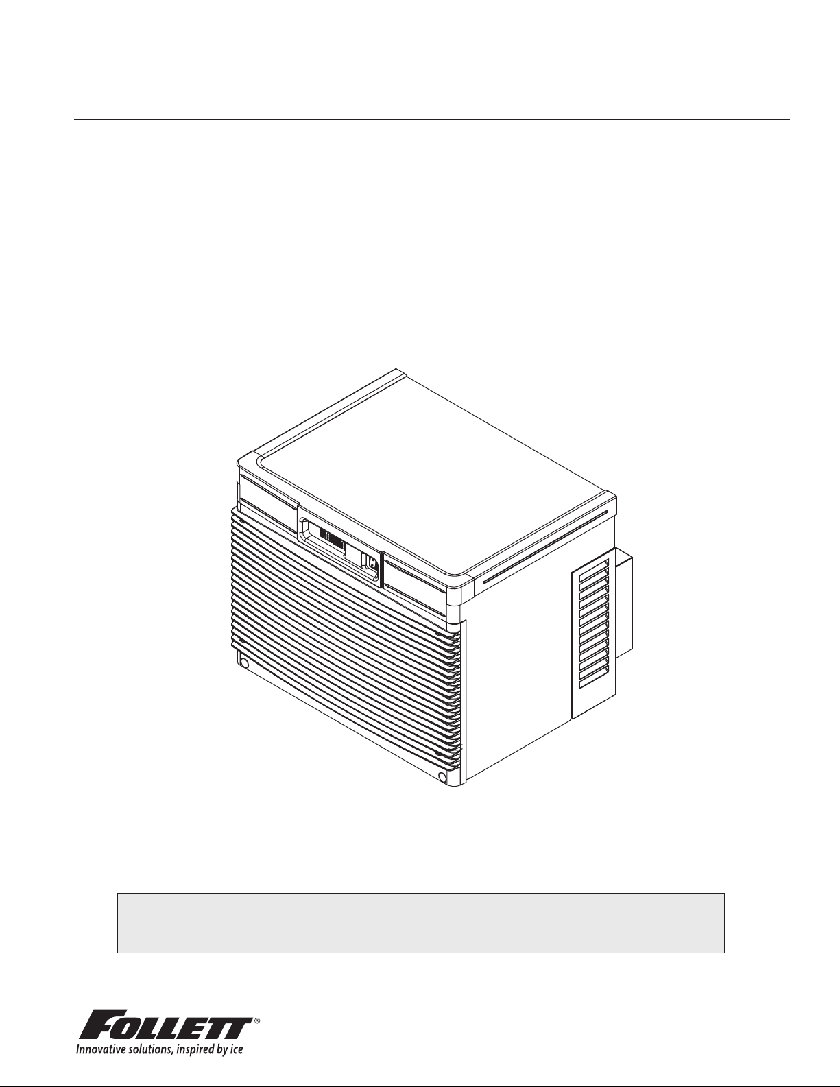
Horizon Elite™ Ice Machines (Self-contained)
Order parts online
www.follettice.com
Operation and Service Manual
After Serial Number L60417
Following installation, please forward this manual
to the appropriate operations person.
801 Church Lane • Easton, PA 18040, USA
HCC1010A/W, HCD1010A/W, HCC1410A/W, HCD1410A/W 1
Toll free (877) 612-5086 • +1 (610) 252-7301
www.follettice.com
01096106R05

Contents
Welcome to Follett. . . . . . . . . . . . . . . . . . . . . . . . . . . . . . . . . . . . . . . . . . . . . . . . . . . . . . . . . . . . . . . . . . . . . . . . . . . . . . 3
Before you begin ............................................................................... 3
Specications ................................................................................. 4
Operation ..................................................................................... 7
Preventive maintenance ....................................................................... 7
Weekly exterior care .......................................................................... 7
Service .......................................................................................11
The Horizon ice machine overview ..............................................................11
Harvest system diagram .......................................................................11
Water system diagram ....................................................................... 13
Water level diagram ......................................................................... 13
Normal control board operation ................................................................ 14
DIP Switch Settings ......................................................................... 14
Error faults: ............................................................................... 15
Soft errors: ................................................................................ 15
Run errors: ................................................................................ 15
Evaporator ushing sequence: ................................................................. 15
Wiring diagram ............................................................................. 16
Fan motor data ............................................................................. 17
Mechanical System ............................................................................ 18
Reservoir/rear bushing disassembly ............................................................ 25
1010 - Refrigerant pressure data ............................................................... 26
1410 - Refrigerant pressure data ............................................................... 26
Refrigeration system diagram .................................................................. 26
Refrigeration charge ......................................................................... 27
Refrigerant replacement requirements ........................................................... 27
Evacuation ................................................................................ 27
Ice capacity test ............................................................................ 27
Troubleshooting .............................................................................. 28
Replacement parts ............................................................................ 30
2 HCC1010A/W, HCD1010A/W, HCC1410A/W, HCD1410A/W
Welcome to Follett
Follett equipment enjoys a well-deserved reputation for excellent performance, long-term reliability and outstanding
after-the-sale support. To ensure that this equipment delivers the same degree of service, we ask that you review
the installation manual (provided as a separate document) before beginning to install the unit. Our instructions are
designed to help you achieve a trouble-free installation. Should you have any questions or require technical help at
any time, please call our technical service group at (877) 612-5086 or +1 (610) 252-7301.
Before you begin
After uncrating and removing all packing material, inspect the equipment for concealed shipping damage. If
damage is found, notify the shipper immediately and contact Follett Corporation so that we can help in the ling of
a claim, if necessary.
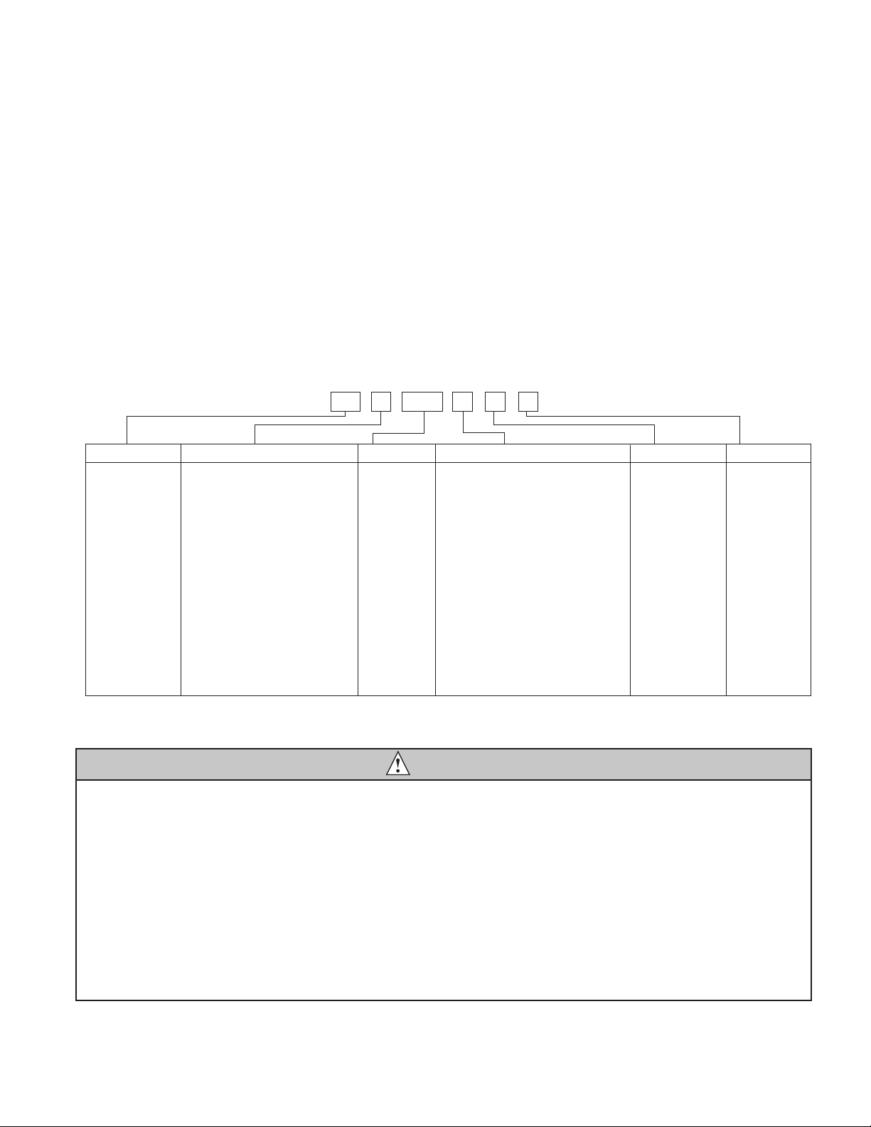
Check your paperwork to determine which model you have. Follett model numbers are designed to provide
information about the type and capacity of Follett equipment. Following is an explanation of the different model
numbers in the series.
Chewblet® Ice Machine Model Number Configurations
HC 1810D SVA
ConfigurationApplication
S RIDE™
(RIDE remote
ice delivery
equipment)
T Top-mount
MC Maestro™
Chewblet
(425 Series)
HC Horizon
Chewblet
(710, 1010,
1410, 1810,
2110 Series)
HM Horizon
Micro Chewblet
C 208-230/60/1 (icemaking head)
®
Self-contained only.
D 115/60/1 (icemaking head)
Self-contained and remote. If remote
unit, high side is 208-230/60/1.
E 230/50/1 (icemaking head)
Self-contained only.
F 115/60/1 (icemaking head)
Remote only. High side is
208-230/60/3.
425 up to
425 lbs
(193 kg)
710 up to
675 lbs
(306 kg)
1010 up to
1061 lbs
(482 kg)
1410 up to
1466 lbs
(665 kg)
1810 up to
1790 lbs
(812 kg)
2110 up to
2039 lbs
(925 kg)
CondenserSeriesVoltageIcemaker
A Air-cooled, self-contained
W Water-cooled, self-contained
R Air-cooled, remote condensing unit
N Air-cooled, no condensing unit for
connection to parallel rack system
V Vision™
H Harmony™
B Ice storage bin
J Drop-in
M Ice Manager
diverter valve
system
P Cornelius Profile
PR150
CAUTION
• Warranty does not cover exterior or outside installations.
• Moving parts. Do not operate with front cover removed.
• Hot parts. Do not operate with cover removed.
• To reduce risk of shock, disconnect power before servicing.
• Drain line must not be vented.
• Water supply must have particle ltration.
• Most ice machine cleaners contain citric or phosphoric acid, which can cause skin irritation. Read caution label
on product and follow instructions carefully.
• Ice is slippery. Maintain counters and oors around dispenser in a clean and ice-free condition.
• Ice is food. Follow recommended cleaning instructions to maintain cleanliness of delivered ice.
HCC1010A/W, HCD1010A/W, HCC1410A/W, HCD1410A/W 3
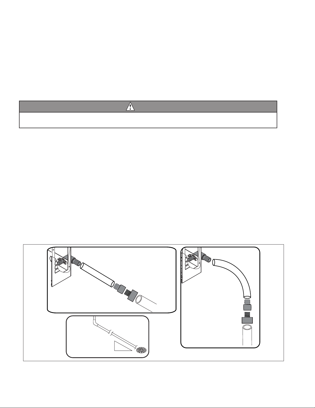
Specications
3/4" barb x 3/4" FPT
1" Stand pipe/Drain
2 ft. x 1" OD
silicone tubing
Minimum 8"
radius
3/4" MPT x 1" slip
1" PVC Drain
2 ft. x 1" OD
silicone tubing
3/4" MPT x 1" slip
3/4" barb x 3/4" FPT
1'
1/4" per foot
(6,4 mm per 0,3 m)
Electrical
Each ice machine requires its own separate circuit with electrical disconnect within 10 ft (6m).
Equipment ground required.
Standard electrical:
§ HCC1010: 208-230/60/1 (6 ft (2m) NEMA 6-15 cord and plug provided)
§ HCC1410: 208-230/60/1 (6 ft (2m) NEMA 6-20 cord and plug provided)
§ Amperage: 1010A/W - 11A
1410A/W - 14A
Plumbing
WARNING
This equipment to be installed with adequate backow protection to comply with applicable federal, state,
and local codes.
§ 3/8" OD push-in water inlet (connection inside machine) - 3/8" OD tubing required
§ 3/4" MPT drain
§ 1/4" FPT condenser inlet (water-cooled condenser only)
§ 1/4" FPT condenser drain (water-cooled condenser only)
Notes:
§ Water shut-off recommended within 10 feet (3m).
§ Water supply must have particle ltration. Follett recommends the lter system that has integral scale inhibitors.
(Follett item# 00130286).
§ Follett does not recommend the use of water softeners or bowl scale inhibitors.
Flush drain plumbing
§ 3/4" MPT ush drain connection at the rear of the machine.
§ Drain must slope 1/4" inch per foot (6 mm per 30.4 cm).
§ Drain line should not be shared with any other piece of equipment.
§ Drain line cannot be reduced to a size smaller than 1 inch.
§ Drain should be piped without a vent.
4 HCC1010A/W, HCD1010A/W, HCC1410A/W, HCD1410A/W
Ambient
Air temperature 100 F/38 C max. 50 F/10 C min.
Water temperature 90 F/32 C max. 45 F/7 C min.
Water pressure – potable 70 psi max. (483 kPa) 10 psi min. (89 kPa)
Heat rejection
1010 1410
Air-cooled 11,300 BTU/hr 16,000 BTU/hr
Water-cooled 12,800 BTU/hr 16,400 BTU/hr
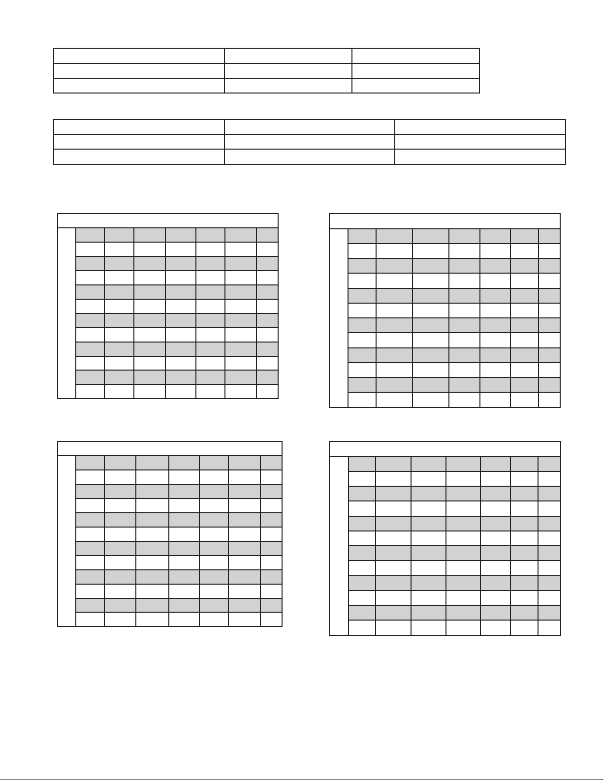
Ice production
1010 Air-cooled ice machine capacity/24 hrs.
Ambient Air Temperature F/C
F 60 70 80 90 100
C 16 21 27 32 38
50 1160 1061 962 825 688 lbs
10 526 481 436 3 74 312 kg
60 1093 1001 909 795 681 lbs
16 496 454 412 361 309 kg
70 1026 941 857 765 674 lbs
21 465 427 389 345 306 kg
80 971 893 815 730 644 lbs
27 440 405 370 331 292 kg
90 917 845 773 694 614 lbs
Evap Potable Water Temperature F/C
32 416 383 351 315 279 kg
1410 Air-cooled ice machine capacity/24 hrs.
Ambient Air Temperature F/C
F 60 70 80 90 10 0
C 16 21 27 32 38
50 1593 1466 1339 1230 1121 lbs
10 723 665 609 558 508 kg
60 1518 1396 1275 116 3 1052 lbs
16 689 633 578 528 477 kg
70 1442 1327 12 11 1097 982 lbs
21 654 602 549 498 445 kg
80 1394 1272 115 0 1050 950 lbs
27 632 577 522 476 431 kg
90 1345 1217 1089 1004 918 lbs
Evap Potable Water Temperature F/C
32 610 552 494 455 416 kg
1010 Water-cooled ice machine capacity/24 hrs.
Condenser Water Temperature F/C
F 50 60 70 80 90
C 10 16 21 27 32
50 1096 1043 1011 947 892 lbs
10 497 473 454 430 405 kg
60 1006 970 938 888 839 lbs
16 456 440 425 403 381 kg
70 917 898 8 74 830 778 lbs
21 416 407 396 376 353 kg
80 874 888 830 787 749 lbs
27 396 403 376 357 340 kg
90 831 807 778 74 5 712 lbs
32 377 366 353 338 323 kg
Evap Potable Water Temperature F/C
1410 Water-cooled ice machine capacity/24 hrs.
Condenser Water Temperature F/C
F 50 60 70 80 90
C 10 16 21 27 32
50 1393 1368 1343 1328 1313 lbs
10 632 621 609 602 596 kg
60 1374 1326 1278 1268 1257 lbs
16 623 6 01 580 575 570 kg
70 1335 1284 1213 1207 1201 lbs
21 606 582 550 547 545 kg
80 1278 1216 1153 11 3 5 1116 lbs
27 580 552 523 515 506 kg
90 1201 1147 1093 1063 1032 lbs
32 545 520 496 482 468 kg
Evap Potable Water Temperature F/C
HCC1010A/W, HCD1010A/W, HCC1410A/W, HCD1410A/W 5
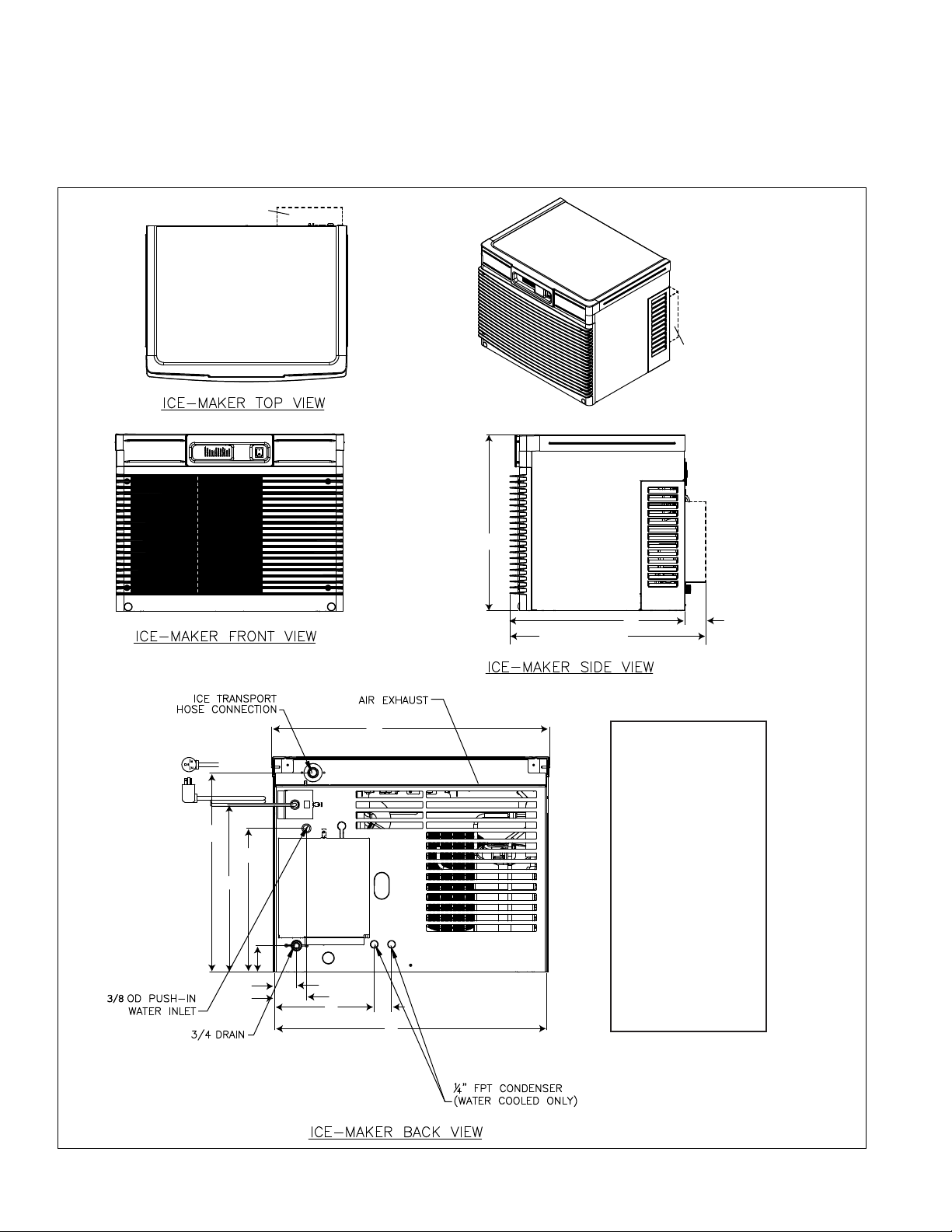
Dimensions and clearances
§ Entire front of ice machine must be clear of obstructions/connections to allow removal.
§ 1" (26mm) clearance above ice machine for service.
§ 1" (26mm) minimum clearance on sides.
§ The intake and exhaust air grilles must provide at least 250 sq in (1615 sq cm) of open area.
§ Air-cooled ice machines – 18" (458 mm) minimum clearance between discharge and air intake-grilles.
1410 ONLY
1410 ONLY
1010: NEMA 6-15
1410: NEMA 6-20
E
F
A
C (1410 ONLY)
N
B
A 22.51" (57.2 cm)
D (1410 ONLY)
B 22.48" (57.1 cm)
C 25.15" (56.3 cm)
D 2.66" (6.8 cm)
E 20.84" (52.9 cm)
F 17.49" (44.4 cm)
G
G 15.00" (38.1 cm)
H 2.73" (6.9 cm)
I 2.30" (5.8 cm)
J 3.34" (8.5 cm)
H
I
J
K
L
M
K 10.44" (26.5 cm)
L 1.81" (4.6 cm)
M 28.50" (72.4 cm)
N 29.15" (74.0 cm)
6 HCC1010A/W, HCD1010A/W, HCC1410A/W, HCD1410A/W
Operation
Cleaning/sanitizing and preventive maintenance (all models)
Note: Do not use bleach to sanitize or clean the icemaker.
Preventive maintenance
Periodic cleaning of Follett’s icemaker system is required to ensure peak performance and delivery of clean,
sanitary ice. The recommended cleaning procedures that follow should be performed at least as frequently as
recommended, and more often if environmental conditions dictate.
Cleaning of the condenser can usually be performed by facility personnel. Cleaning of the icemaker system,
in most cases, should be performed by your facility’s maintenance staff or a Follett authorized service agent.
Regardless of who performs the cleaning, it is the operator’s responsibility to see that this cleaning is performed
according to the schedule below. Service problems resulting from lack of preventive maintenance will not be
covered under the Follett warranty.
Weekly exterior care
The exterior may be cleaned with a stainless cleaner such as 3M Stainless Steel Cleaner & Polish or equivalent.
Monthly condenser cleaning (air-cooled icemaker only)
1. Use a vacuum cleaner or stiff brush to carefully clean condenser coils of air-cooled icemakers to ensure
optimal performance.
2. When reinstalling counter panels in front of remote icemakers, be sure that ventilation louvers line up with
condenser air duct.
Semi-annual evaporator cleaning (every 6 months)
WARNING
• Wear rubber gloves and safety goggles (and/or face shield) when handling ice machine cleaner or sanitizer.
CAUTION
• Use only Follett approved SafeCLEAN Plus™ cleaning solution.
• DO NOT USE BLEACH.
• It is a violation of Federal law to use these solutions in a manner inconsistent with their labeling.
• Read and understand all labels printed on packaging before use.
Note: Complete procedure for cleaning an sanitizing MUST be followed. Ice must be collected for 10minutes
before putting ice machine back into service.
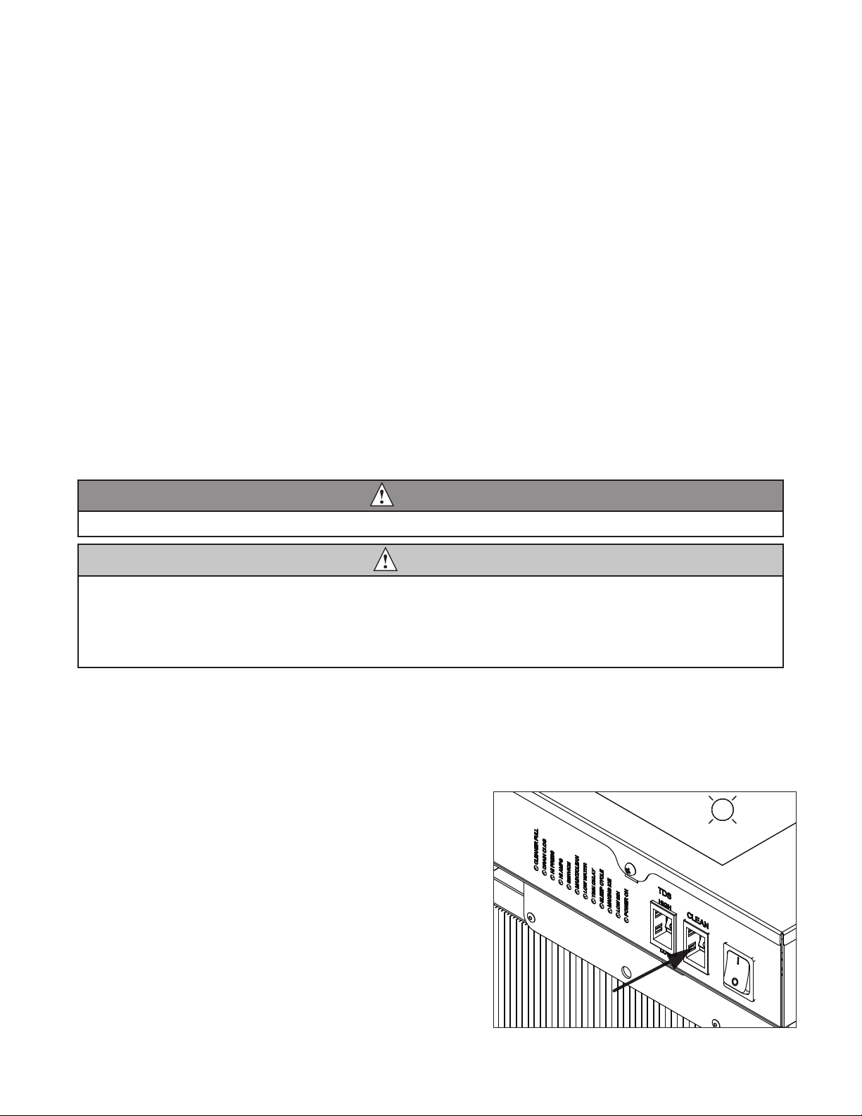
Fig. 1
1. Press the CLEAN button. The machine will drain. The
auger will run for a short time and then stop. Wait for
the LOW WATER light to come on.
LO WATER
HCC1010A/W, HCD1010A/W, HCC1410A/W, HCD1410A/W 7
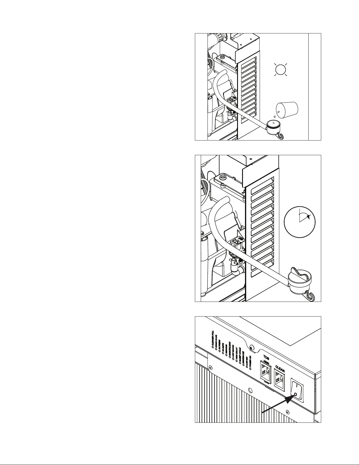
2. Follow the directions on the SafeCLEAN Plus
packaging to mix 1 gal. (3.8 L) of Follett SafeCLEAN
Plus solution. Use 100 F (38 C) water.
3. Using a 1 quart (1L) container, slowly ll cleaning cup
until CLEANER FULL light comes on. Do not overll.
4. Place one Sani-Sponge™ in remaining sanitizing and
cleaning solution and retain for Step 9.
Note: Do not use bleach to sanitize or clean the icemaker.
5. Replace cover on cleaner cup. Machine will clean,
then ush 3 times in approximately 15 minutes. Wait
until machine restarts.
Fig. 2
CLEANER FULL
Fig. 3
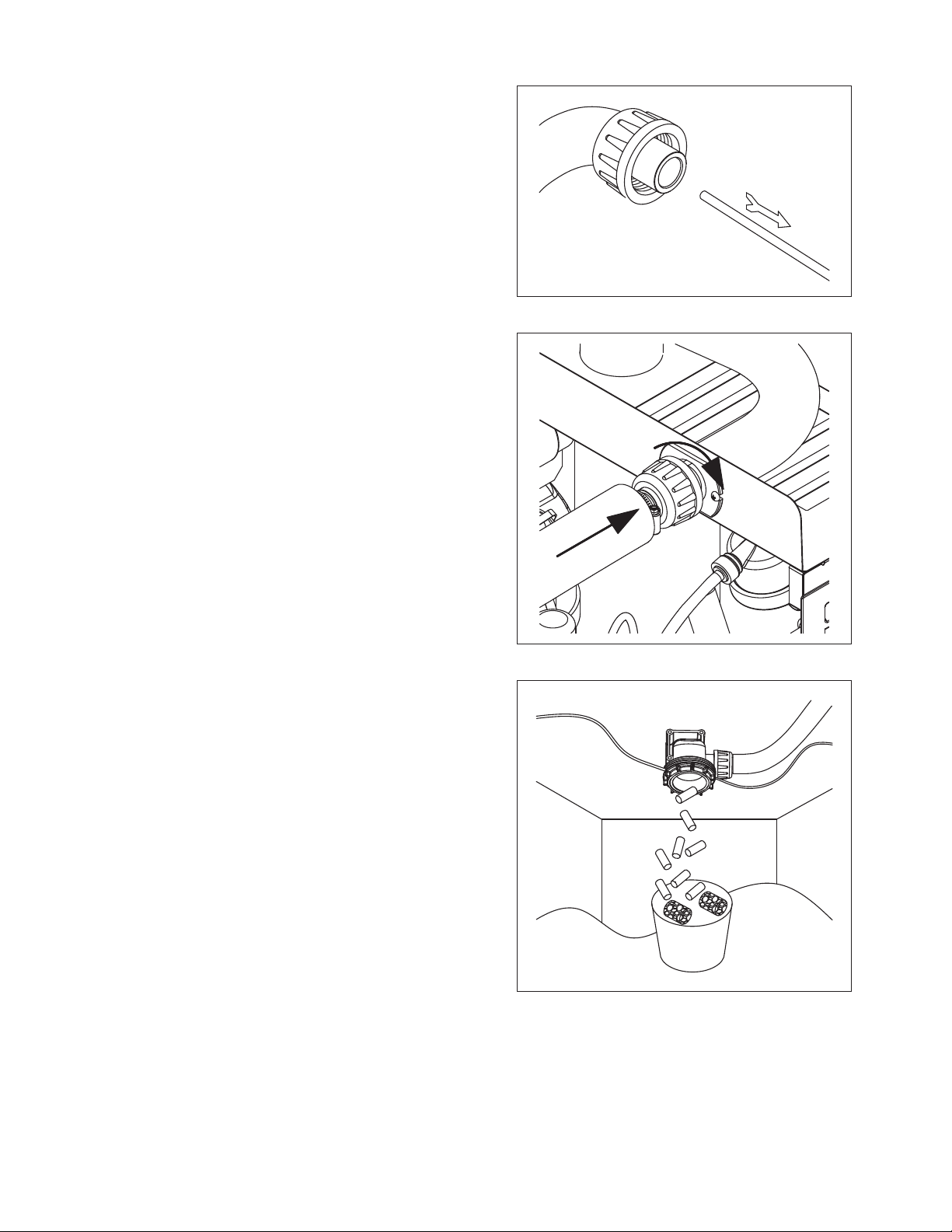
6. To clean/sanitize ice transport tube – Press power
switch OFF
15
Fig. 4
8 HCC1010A/W, HCD1010A/W, HCC1410A/W, HCD1410A/W
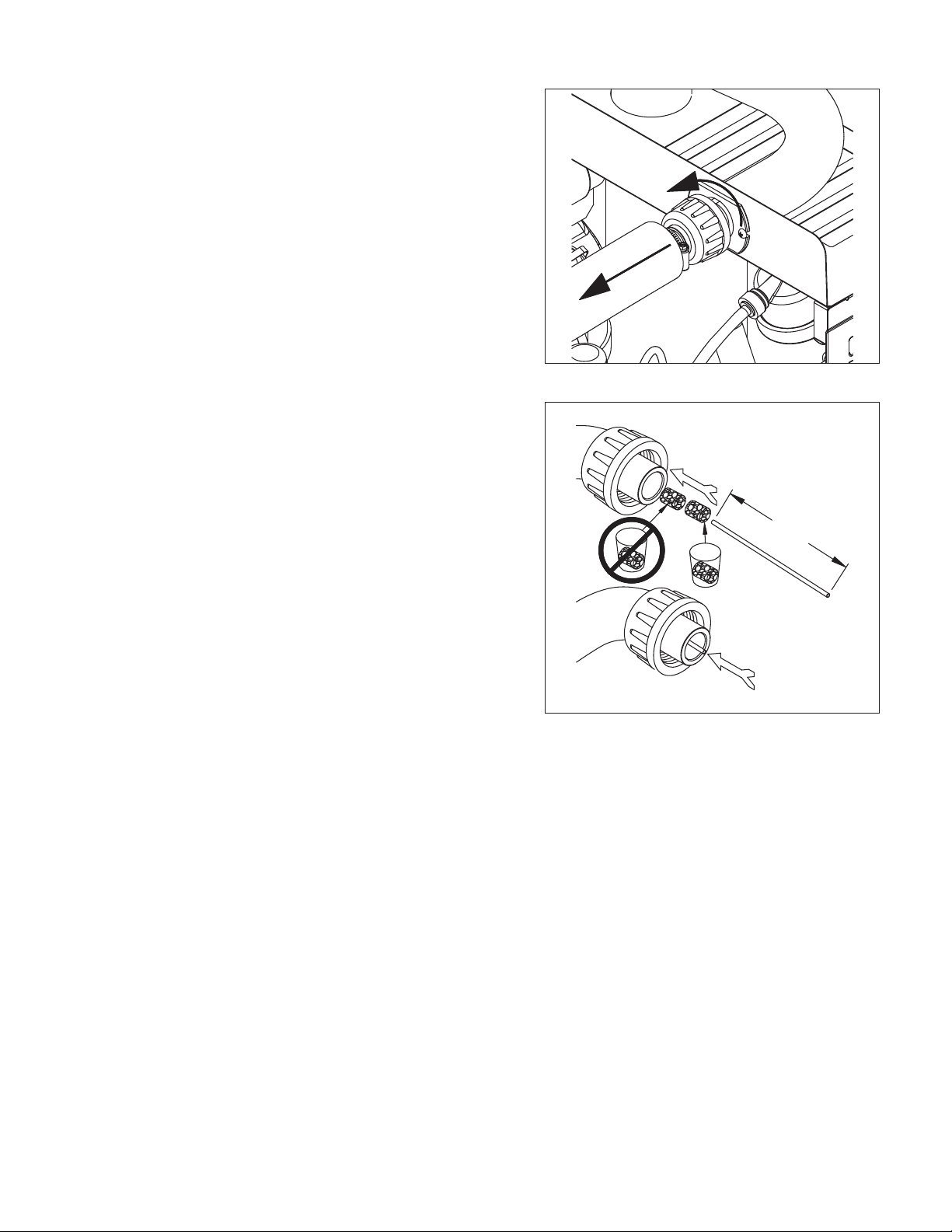
7. Disconnect coupling as shown.
8. Using disposable food service grade gloves, insert
dry Sani-Sponge.
9. Insert Sani-Sponge soaked in SafeClean Plus (from
Step 4).
10. Push both Sani-Sponges down ice transport tube
with supplied pusher tube.
Fig. 5
Fig. 6
1
16"
(407 mm)
2
3
HCC1010A/W, HCD1010A/W, HCC1410A/W, HCD1410A/W 9
11. Remove and discard 16 inch (407 mm) pusher tube.
12. Reconnect coupling. Press power switch ON. Ice
pushes Sani-Sponges through ice transport tube.
Fig. 7
Fig. 8
13. Place a sanitary (2 gal. or larger) container in bin
or dispenser to collect Sani-Sponges and ice for 10
minutes.
14. Collect 5.5 lbs (3 kg) of ice from unit. Discard ice and
Sani-Sponges.
Fig. 9
10 HCC1010A/W, HCD1010A/W, HCC1410A/W, HCD1410A/W
Service
Ice machine operation (all models)
Follett’s ice machine consists of ve distinct functional systems covered in detail as follows:
§ Water system
§ Electrical control system
§ Mechanical assembly
§ Refrigeration system
§ Bin full
The Horizon ice machine overview
The Follett Horizon ice machine uses a horizontal, cylindrical evaporator to freeze water on its inner surface. The
refrigeration cycle is continuous; there is no batch cycle. The evaporator is ooded with water and the level is
controlled by sensors in a reservoir. A rotating auger (17 RPM) continuously scrapes ice from the inner wall of the
evaporator. The auger moves harvested ice through the evaporator into an ice extrusion canal. The ice is forced
through a restrictive nozzle that squeezes out the water and creates the Chewblet. The continuous extrusion
process pushes the Chewblets through a transport tube into a dispenser or bin.
A solid state PC board controls and monitors the functionality of the ice machine. In addition to sequencing
electrical components, the board monitors various operational parameters. A full complement of indicator lights
allows visual status of the machine's operation. Additionally, the PC board controls the self-ushing feature of the
ice machine. The evaporator water is periodically drained and replenished to remove minerals and sediment.
A unique “bin full” detection system is incorporated in the Horizon ice machine. A switch located at the ice
discharge port of the machine detects the position of the transport tube. When the bin lls up with ice, the transport
tube moves out of the normal running position, and the switch turns the ice maker off. A domed housing at the end
of the transport tube contains the ice extrusion loads during shut down.
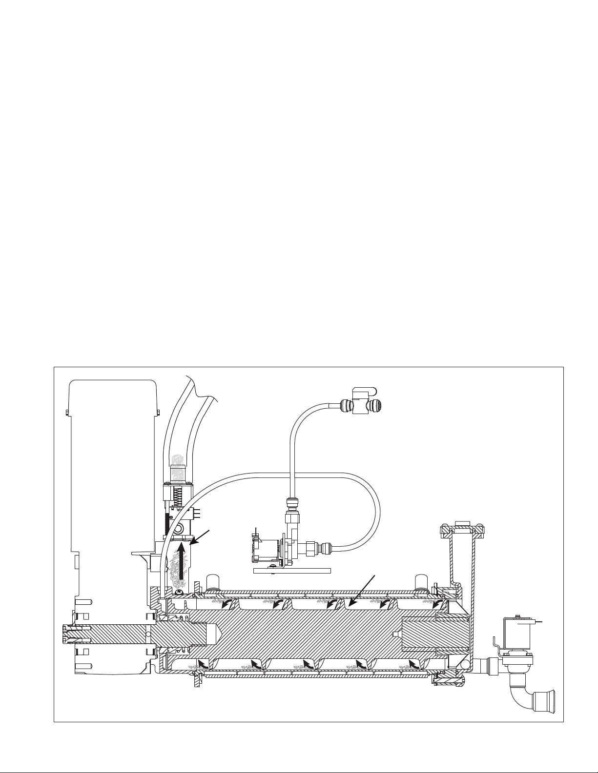
Harvest system diagram
Ice Transport Tube
Water Inlet
Compression
Nozzle
Auger
HCC1010A/W, HCD1010A/W, HCC1410A/W, HCD1410A/W 11
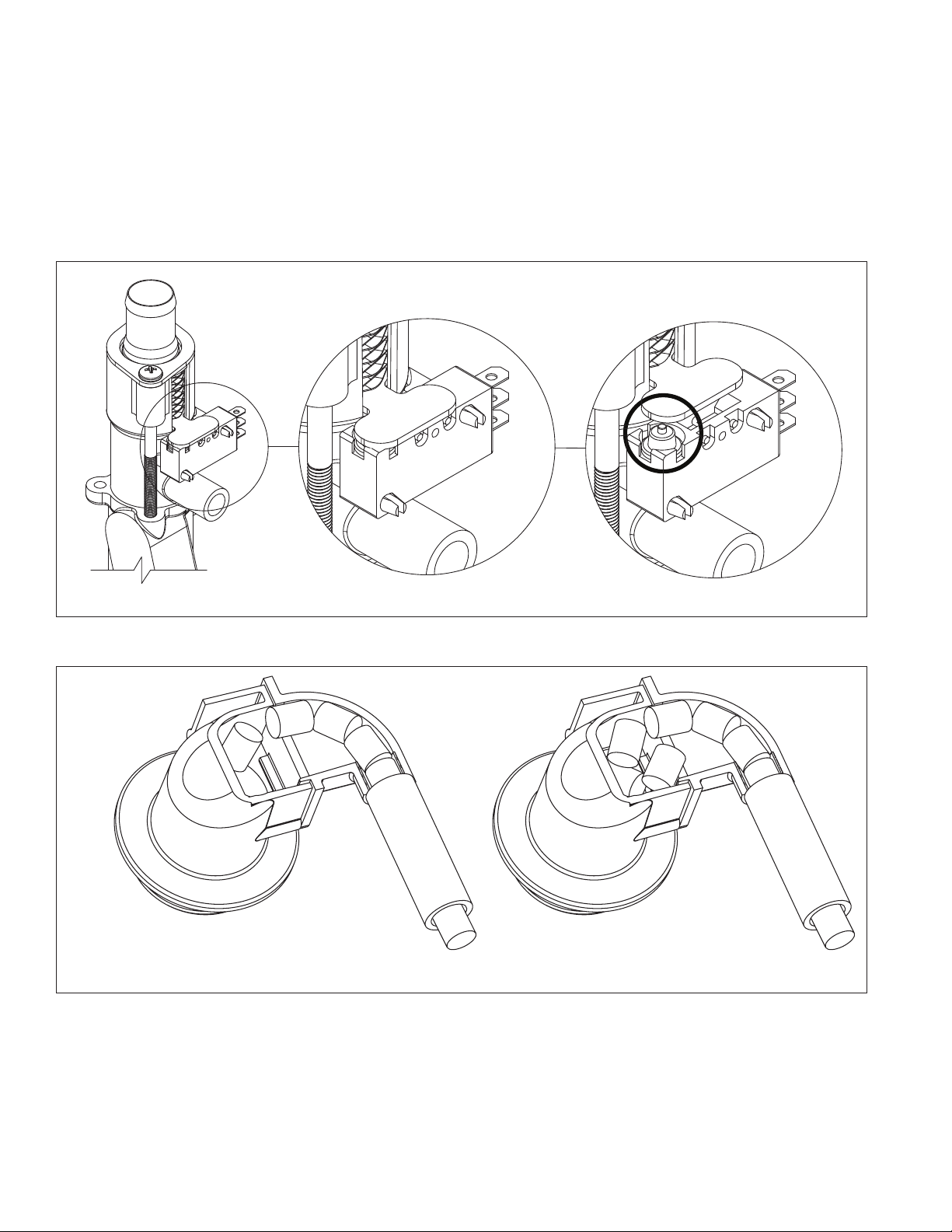
“Bin full” detection system
The Follett Horizon ice machine incorporates a unique “bin full” detection system that consists of the shuttle and
actuator. The shuttle incorporates a ag and switch. Referencing the gure below, the normal running position
of the ag is down, and the switch is closed. When the bin lls to the top and ice can no longer move through
the tube, the machine will force the shuttle ag up, opening the switch and shutting the machine off. The shuttle
actuator, located above the ice bin allows the ice to curl up within it when the bin is full. In this way, there are no
loads generated that would tend to lift off the lid of the bin.
Shuttle ag and sensor
Shuttle actuator
Running
Running Off
Off
12 HCC1010A/W, HCD1010A/W, HCC1410A/W, HCD1410A/W
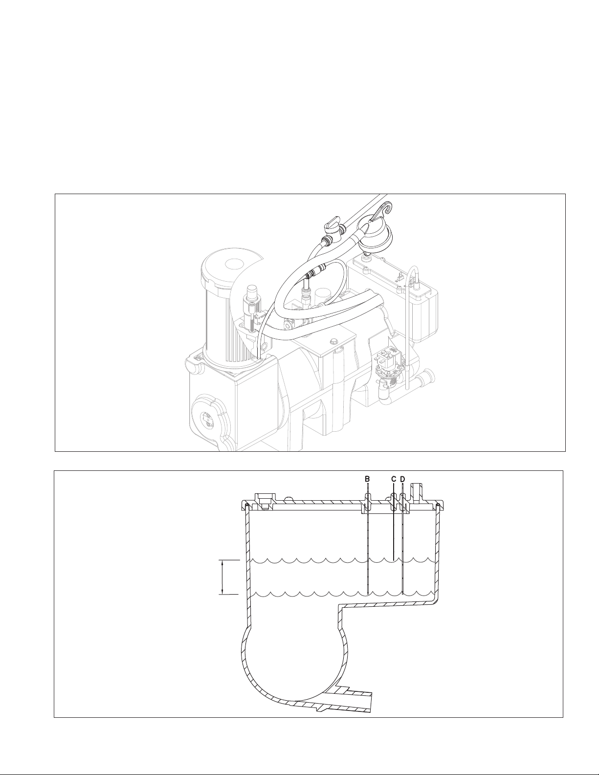
Water system
The water level in the evaporator is controlled by a feed solenoid and level detecting sensors. Referencing the
diagram below, water sensing probes extend down into the reservoir at the end of the evaporator assembly. The
system works via electrical conductivity as follows:
The probe labeled B is the common. When water is between any of the other probes and the common, the PC
board will sense the activation. During normal operation, the water level rises and falls between the Normal
High and Normal Low probes. As water is consumed to make ice, the level will fall until the Normal Low probe is
exposed, triggering the water feed solenoid on. Water will ll until the Normal High sensor is activated.
Note: The potable water total dissolved solids (TDS) content must be greater than 10 ppm for the water control
system to function properly. If using reverse osmosis water ltration system, ensure TDS level is greater than
10 ppm.
Water system diagram
Water level diagram
Common
Normal Hi
Normal Lo
Normal
Operating
Range
HCC1010A/W, HCD1010A/W, HCC1410A/W, HCD1410A/W 13
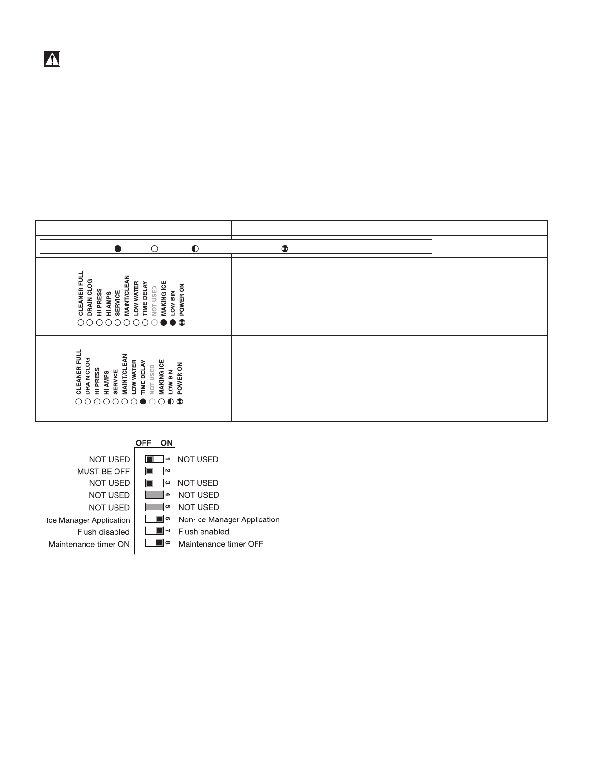
Electrical system
FLASHINGON or OFF
Legend:
OFFON
ATTENTION!
To prevent circuit breaker/Hi-amp overload, wait 5 minutes before
restarting this unit. This allows the compressor to equalize and the
evaporator to thaw.
Normal control board operation
The PC board indicator lights provide all the information necessary to determine the machine's status. Green
indicator lights generally represent “go” or normal operation; Yellow indicators represent normal off conditions; Red
indicators generally represent alarm conditions.
A ashing green light labeled POWER indicates power to the machine. All other normal operation status indicators
are covered as follows:
Ice machine disposition Operating conditions
1. Ice machine is making ice.
.
2. Ice machine is not making ice.
DIP Switch Settings
1. Normal running.
2. Normal time delay. When the bin lls with ice, the LOW BIN
light goes out momentarily and the refrigeration and auger
drive systems immediately shut down. (Note: The fan motor
will continue to run for 10 minutes to cool condenser) The TIME
DELAY light comes on, initiating the time delay period. When the
time delay expires, the machine will restart provided that the LOW
BIN light is on.
14 HCC1010A/W, HCD1010A/W, HCC1410A/W, HCD1410A/W
 Loading...