


Ice Pro™ DB1000 Series Automatic
Ice Bagging and Dispensing System
Order parts online www.follettice.com
Installation, Operation and Service Manual
Following installation, please forward this manual to the appropriate operations person.
801 Church Lane • Easton, PA 18040, USA |
|
Toll free (877) 612-5086 • +1 (610) 252-7301 |
00109710R13 |
www.follettice.com |

Table of contents
Welcome to Follett Corporation |
|
3 |
|
Important cautions |
3 |
Specifications |
4 |
Installation |
6 |
Door entry |
6 |
Locating unit |
9 |
Leg extension accessory |
9 |
Leveling |
9 |
Utility connections |
9 |
Foot pedal |
9 |
Bag wicket |
10 |
Sanitize |
10 |
Icemaker |
10 |
Adjustments |
10 |
Cleaning and sanitizing |
11 |
Exterior care |
11 |
Interior care |
11 |
Semi-annual cleaning |
11 |
Operation |
12 |
How the dispenser works |
12 |
System overview |
12 |
Control functions |
13 |
Bag pins – installing wickets |
14 |
Adjusting bag stand height |
14 |
Using Totes™ or other containers |
14 |
Using SmartCART™ or other mobile ice storage devices |
14 |
Removing bag stand |
14 |
Service |
15 |
Agitator removal |
15 |
Wiring diagram |
16 |
Troubleshooting guide |
17 |
Replacement parts |
19 |
|
|
2

Welcome to Follett
Follett ice dispensers enjoy a well-deserved reputation for excellent performance, long-term reliability and outstanding after-the-sale support. To ensure that this dispenser delivers that same degree of service, we ask that you take a moment to review this manual before beginning the installation of the dispenser. Should you have any questions or require technical help at any point, please call our technical service group, (877) 612-5086 or +1 (610) 252-7301.
Before you begin
After uncrating and removing all packing material, inspect the equipment for concealed shipping damage. If damage is found, notify the shipper immediately and contact Follett Corporation so that we can help in the filing of a claim, if necessary.
Check your paperwork to determine which model you have. Follett model numbers are designed to provide information about the type and capacity of Follett ice dispensing equipment. Following is an explanation of the different model numbers in the DB1000 series.
DB1000SA
SA = Semi-Automatic ice dispensing and bagging
1000 – 1000 lbs maximum bin capacity
DB – Dispensing bin - 220/60 Hz EDB – Dispensing bin - 230/50 Hz
!Important cautions
Storage area of dispenser contains mechanical, moving parts. Keep hands and arms clear of this area at all times. If access to this area is required, power to unit must be disconnected first.
Ice is slippery. Maintain counters and floors around dispenser in a clean and ice-free condition.
Ice is food. Follow recommended cleaning instructions to maintain cleanliness of delivered ice.
Should local codes require a hard-wired connection and/or shielded wiring, eliminate the cord(s) and plug(s) and follow the appropriate wiring diagram.
Dispenser can accommodate most cube/cubelet ices up to 1" square or Chewblet® ice (made by Horizon ice machines). Crushed, flake, or nugget ice cannot be used. Use of these ices can jam dispenser and void warranty. For questions about ice compatibility, call Follett’s customer service group toll free at (877) 612-5086 or +1 (610) 252-7301.
Always disconnect power before cleaning or servicing the dispenser.
Failure to remove all sanitizer may result in health hazard.
3
Specifications
Electrical
Each icemaker and dispenser requires separate circuit. Equipment ground required.
Standard electrical - 220V, 60Hz, 1 phase, Max. fuse – 5 amps, 15 amp circuit. Cord and plug provided.
Plumbing
Drain 1" PVC FPT for hopper drain
Note: Drains should be hard piped and insulated. Maintain at least 1/4" per foot (1cm per 31cm run) slope on drain line run
Clearance and access information
Door entry Installation sites must have an unobstructed path to installation location with door openings no less than 34.25" (870mm)
Service Clearance A minimum of 12" (305mm) to left of unit is necessary for service
Ice type
Dispenser can accommodate most cube/cubelet ices up to 1" square or Chewblet ice (made by Horizon ice machines). Crushed, flake, or nugget ice cannot be used. Use of these ices can jam dispenser and void warranty.
For questions about ice compatibility, call Follett’s technical service group toll free at (877) 612-5086 or
+1 (610) 252-7301.
Icemaker weight limit
Icemaker(s) mounted on thin top may not exceed 800 lbs (364kg)
Icemaker(s) mounted on thick top may not exceed 1300 lbs (590kg)
Container sizes
Standard unit accommodates bag sizes up to 20 lbs (9kg) / 27.35" (696mm)
Standard dispense chute compatible with carts and containers up to 29.5" (750mm) high
Optional 6.5" (166mm) leg extension kit may be purchased to allow for up to 36" (915mm) high carts and bags up to 40 lbs (18kg) and 33.85" (860mm) high
Bag pins
Bag pins may be adjusted to accommodate bag hole centers from 5" (127mm) to 10" (254mm)
4
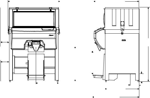
Dimensions and clearances
12" (305mm) Service Clearance
Front view |
|
|
|
|
|
|
|
|
|
|
Side view |
|||
52.0" |
|
|
|
|
|
|
|
45.5" |
||||||
|
|
|
||||||||||||
|
(1321mm) |
|
|
|
|
|
|
|
|
|
|
|
|
(1156mm) |
|
|
|
|
|
|
|
|
|
|
|
|
|
|
|
|
|
|
|
|
|
|
|
|
|
|
|
|
|
|
|
|
|
|
|
|
|
|
|
|
|
|
|
|
|
|
|
|
|
|
|
|
|
|
|
|
|
|
|
|
|
|
|
|
|
|
|
|
|
|
|
|
|
|
|
|
|
|
|
|
|
|
|
|
|
|
|
|
|
|
|
|
|
|
|
|
|
|
|
|
|
|
|
|
|
|
|
|
|
|
|
|
|
|
|
|
|
|
|
|
31" |
27.35" |
(788mm) |
(695mm) |
max. cart |
max. bag |
|
|
|
|
|
|
|
|
|
|
|
|
|
|
|
|
|
|
|
|
|
|
|
|
|
|
|
|
|
|
|
|
|
|
|
|
|
|
|
|
|
|
|
|
|
|
|
|
|
|
|
|
|
|
|
|
|
|
|
|
|
|
|
|
|
|
|
|
|
|
22.5" (572mm) |
|
|
|
|
|
|
34" |
|
|||||
|
|
|
|
||||||||||
1" FPT drain |
|
|
|
|
|
|
|
||||||
|
|
|
|
|
(864mm) |
||||||||
|
|
||||||||||||
|
|
|
|
|
|
|
|
|
|
|
|||
|
|
|
|
|
|
|
|
|
|
46.75" |
|
||
|
|
|
|
|
|
|
|
|
|
(1188mm) |
|||
71.75"
(1823mm)
7"
(18mm)

 9.5" (242mm) 1" FPT
drain
Notes
Special top required for icemakers weighing more than 800 lbs (364kg). Adds an additional 2.125" (54mm) to height. Contact factory.
Add 2" (51mm) to depth and 10 lbs (4.5kg) to shipping weight when drain pan accessory used.
5

Installation
Door Entry
Some disassembly may be necessary to gain access through door openings with a width of 34.25" (850mm) to 45.5" (1156mm).
Note: Disassembly is NOT necessary for gaining entry through door openings larger than 45.5" (1156mm)
1. Remove lower splash panel with four screws (Fig. 1.1).
Fig. 1
1 |
2.Detach the following plugs from the left side of control box:
a)Window interlock J26 (Fig. 2.1)
b)Control J21 (Fig. 2.2)
c)PCB power J22 (Fig. 2.3)
d)Auger motor J24 (Fig. 2.4) (model DB1000SA only)
3.Remove control panel cover by lifting and detaching hook and loop tape (Fig. 3.1).
4.Remove lower cover with two thumbscrews, one from each side (Fig. 3.2).
Fig. 2
1 – WINDOW INTERLOCK J26 FOOTSWITCH J27
2 – CONTROL J21
3 – PCB POWER J22
AGITATION MOTOR J23 4 – AUGER MOTOR J24
Fig. 3
1
2
6

5.Remove transfer case with two latches (Fig. 4.1).
6.Remove ice deflection plate by lifting up (Fig. 4.2).
7.Remove auger by lifting up (Fig. 4.3).
8.Remove auger tube by lifting up. Note position of locating slot on lower end for reinstallation (Fig. 4.4).
Fig. 4
1 |
2 |
3 |
4 |
9.Remove blower duct by loosening thumb screw, rotating clip (Fig. 5.1) and lifting up (Fig. 5.2).
Fig. 5
2 |
1 |
10. Remove control box/fan motor mounting assembly with two |
Fig. 6 |
screws (Fig. 6). |
|
7

11. |
Remove auger motor bracket with 8 screws (Fig 7). |
Fig. 7 |
12. |
Remove bag pin bracket with two thumbscrews (Fig. 7). |
|
|
||
|
|
|
13.The unit's width may be further reduced by removing the upper ice storage section (Fig. 8). This reduces unit width by
1.75" (45mm) to an overall width of 34" (864mm).
a)Remove window.
b)Pull window interlock switch cable through wire trough in upper right corner of base (Fig. 8.1).
c)Cut tie wrap.
d)Release latch from each side of ice storage section (Fig. 8.2).
e)Lift upper ice storage section from base.
Note: Reinstallation of auger tube requires locating slot be in the
7 o’clock position and upper end of auger be flush to auger motor bracket.
Fig. 8
2 |
1 |
8

Locating unit |
Fig. 9 |
A minimum of 12" (305mm) to the left of the unit must be unobstructed |
|
|
|
|
||
for service clearance (see dimensions and clearances). |
|
|
|
|
||
Leg extension accessory |
|
1 |
|
2 |
||
|
|
|
|
|||
1. |
Raise unit off feet. |
1 |
1 |
2 |
2 |
|
2. |
Remove each standard foot channel with four carriage bolts |
|||||
|
|
|
|
|||
|
(Fig. 9.1). |
|
|
|
|
|
3. |
Remove foot insert and cap insert from standard foot channel. |
|
|
|
|
|
4. |
Align each accessory extension foot channel to the eight |
|
|
|
|
|
|
holes of leg. |
|
|
|
|
|
4.Use the four carriage bolts removed in step 2 and four carriage bolts supplied with leg extension accessory to attach each extension channel to the eight holes of each leg (Fig. 9.2).
6. Place foot insert and cap insert into extension foot channel.
5.Verify each leg is in fully retracted position prior to lowering unit on feet.
6.Follow leveling instructions below.
Leveling |
Fig. 10 |
|
Leveling the unit is important for the proper operation of any |
|
|
|
|
|
top mounted icemaker. The dispenser is shipped with the legs in the |
|
|
fully retracted position. Each leg may be adjusted independently by |
|
|
turning clockwise to lower the leg or counterclockwise to raise the leg. |
|
|
Utility connections |
|
|
Drain |
8.875" |
|
Drain connection is made to the 1" FPT PVC fitting (Fig. 10). Leave |
(226mm) |
|
a minimum of 1/4" per foot (1cm per 31cm run) slope on drain line |
|
|
run. Insulate the entire run length to prevent condensation from |
|
|
forming on outside of drain line. |
|
|
Note: Avoid excessive tightening force when connecting |
22.875" |
drain |
to this fitting. |
(582mm) |
|
Note: Do not apply excessive heat if any sweating of fittings is |
|
|
necessary. Heat conduction through metal may melt |
|
|
threads in plastic drain. |
|
|
Electrical
Make electrical connections in accordance with local and NEC codes. Each icemaker and dispenser requires separate circuit. Equipment ground required.
Standard electrical – 220V, 60Hz, 1 phase. Max. fuse – 5 amps, 15 amp circuit. Cord and plug provided.
Foot pedal
The foot pedal is installed to the dispenser at the factory. Remove packaging and place on floor near bag stand on front of dispenser.
9
 Loading...