

Page 1

GESTRA
GESTRA Steam Systems
NRS 1-51
Installation Instructions 818955-01
Level Switch
NRS 1-51
EN
English
1
Page 2

2
Contents
Page
Application
Usage for the intended purpose ..............................................................................................................4
Function .................................................................................................................................................4
Directives and Standards
Pressure Equipment Directive (PED) 97/23/EC ........................................................................................
Functional Safety acc. to IEC 61508 ........................................................................................................
VdTÜV Bulletin “Wasserstand 100” (= Water Level 100) ..........................................................................
LV (Low Voltage) Directive and EMC (Electromagnetic Compatibility) .......................................................5
ATEX (Atmosphère Explosible) .................................................................................................................5
Functional Safety acc. to IEC 61508
Safety characteristics of the subsystem NRG 1...-51 / NRS 1-51 .............................................................
Terms and abbreviations .........................................................................................................................6
Determination of the Safety Integrity Level (SIL) for safety-related systems .............................................7
Technical Data
NRS 1-51
Name plate / marking ...........................................................................................................................10
Dimensions and Functional Elements
NRS 1-51..............................................................................................................................................11
Important Notes
Safety note ...........................................................................................................................................12
Scope of supply ....................................................................................................................................12
Installation
............................................................................................................................................ 8, 9
5
5
5
6
Mounting level switch NRS 1-51 ........................................................................................................... 13
Page 3

Contents – continued –
Page
Electrical Connection
Mains supply ........................................................................................................................................13
Connection of level electrode ................................................................................................................ 13
Connection of control circuit .................................................................................................................13
Connection of logic unit (standby input).................................................................................................13
Connection for signal output .................................................................................................................14
Tools .....................................................................................................................................................14
Wiring diagram for level switch NRS 1-51 .............................................................................................15
Schematic representations of arrangements .........................................................................................16
Explanatory notes to schematic respresentations .................................................................................. 16
Basic Settings
Factory setting ......................................................................................................................................16
Commissioning Procedure
Checking switchpoint and function .......................................................................................................17
Operation, Alarm and Test
Indicators and adjustors ........................................................................................................................18
Troubleshooting
Indication, diagnosis and remedy .................................................................................................... 18, 19
Further Notes
Action against high frequency interference ...........................................................................................20
Interlock and interlock deactivation .......................................................................................................20
Checking the switchpoints .................................................................................................................... 20
Decommissioning / replacing level switch .............................................................................................20
Disposal................................................................................................................................................20
Note on the Declaration of Conformity / Declaration by the Manufacturer .........................................20
3
Page 4
4
Application
Usage for the intended purpose
The level switch NRS 1-51 is used in conjunction with level electrodes NRG 1...-.. as high level alarm in
steam boilers and (pressurised) hot-water plants.
A high level alarm prevents the water level from exceeding the preset max. water level (HW) and for this
purpose switches off e. g. the feedwater supply.
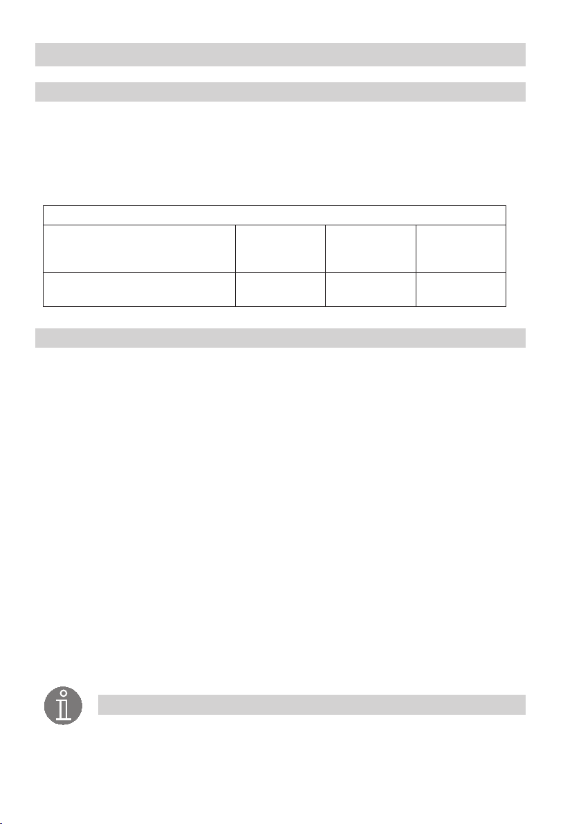
Depending on the specified directives or standards, the level switch NRS 1-51 is intended to be used in
combination with the following level electrodes:
Level electrode NRG 1...-..
PED Pressure Equipment Directive
97/23/EC +
Functional Safety IEC 61508 SIL 3
VdTÜV Bulletin “Wasserstand 100”
(= Water Level 100)
Function
The level switch NRS 1-51 is designed for different electrical conductivities of the boiler water and for
connecting one level electrode.
See section Schematic representations of arrangements on page 16.
When the water level exceeds the MAX limit, the level electrode enters the liquid and an alarm is
triggered in the level switch. This switchpoint is determined by the length of the electrode rod
(level electrode NRG 1...-51, NRG 1...-12).
After the de-energizing delay has elapsed, both output contacts of the level switch will open the control
circuit, e. g. for the feedwater supply. If the deactivation of the feedwater supply is interlocked in the
external control circuit, the lockout can only de deactivated when the level electrode is exposed again.
An alarm will also be raised if a malfunction occurs in the level electrode and/or the electrical connection.
If the level electrode is installed in an isolatable level pot outside the boiler, make sure that the connecting
lines are rinsed regularly.
minutes.
(standby input, controlled by the logic unit SRL 6-50).
If the connecting lines for steam ≥ 40 mm and water ≥ 100 mm, the installation is considered to be
internal. In this case the rinsing processes do not have to be monitored.
An autmatic self-testing routine monitors the safety functions of the level switch. In the event of a
malfunction the control circuit opens instantaneously and switches off e. g. the feedwater supply.
Alarm and malfunction messages are indicated by LEDs, and the signal output is instantaneously
energized.
An alarm can be simulated by pressing the test button.
During the rinsing process the water level cannot be measured in the level pot for 5
The level switch therefore bypasses the level electrode and monitors the rinsing and bypass time
NRG 16-51 NRG 17-51 NRG 19-51
NRG 16-51
NRG 16-12
NRG 17-51
NRG 17-12
NRG 19-51
NRG 19-12
Note
n A high level alarm prevents the water level from exceeding the preset max. liquid
level (HW). For this purpose it can, for instance, interrupt the feedwater supply. If the
interruption of the feedwater supply endangers the heating surfaces in the feedwater
preheater (economizer), the heating must be switched off, too.
Page 5

Directives and Standards
Pressure Equipment Directive (PED) 97/23/EC
The level switch NRS 1-51 in conjunction with level electrode NRG 1...-51 is EC type approved
according to EN 12952/EN 12953. These Directives state, among other things, the requirements made
on limiting systems and equipment for steam boiler plants and (pressurised) hot-water installations.
Functional Safety acc. to IEC 61508
The level switch NRS 1-51 is certified acc. to IEC 61508 only if used in combination with level elec
trode NRG 1...-51. This standard describes the functional safety of safety-related electrical/electronic/
programmable electronic systems.
The equipment combination NRG 1...-51 + NRS 1-51 corresponds to a type B subsystem with Safety
Integrity Level (SIL) 3.
VdTÜV Bulletin “Wasserstand 100” (= Water Level 100)
The level switch NRS 1-51 in conjunction with the level electrodes NRG 1...-51 and NRG 1...-12 is type
approved according to the VdTÜV Bulletin "Water Level 100".
The VdTÜV Bulletin “Wasserstand (=Water Level) 100” specifies the requirements made on water level
control and limiting equipment for boilers.
LV (Low Voltage) Directive and EMC (Electromagnetic Compatibility)
The level switch NRS 1-51 meets the requirements of the Low Voltage Directive 2006/95/EC and the
EMC Directive 2004/108/EC.
ATEX (Atmosphère Explosible)
According to the European Directive 94/9/EC the level switch NRS 1-51 must
explosive areas.
Note
The level electrodes NRG 1...-51, NRG 1...-12 are simple items of electrical equipment
as specified in EN 60079-11 section 5.7. According to the European Directive 94/9/EC
the equipment must be equipped with approved Zener barriers if used in potentially
explosive areas. Applicable in Ex zones 1, 2 (1999/92/EC).
The equipment does not bear an Ex marking. The suitability of the Zener barriers is
certified in a separate document.
Note that the requirements of the IEC 61508 are not met if the NRG 1...-51,
NRG 1...-12 + Zener barriers + NRS 1-51 are interconnected!
not be used in potentially
-
5
Page 6
6
Functional Safety acc. to IEC 61508
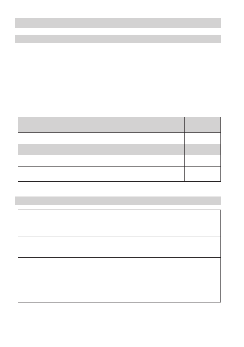
Safety characteristics of the subsystem NRG 1...-51 / NRS 1-51
The level switch NRS 1-51 is certified acc. to IEC 61508 only if used in combination with level electrodes
NRG 1...-51.
The equipment combination NRG 1...-51 / NRS 1-51 corresponds to a type B subsystem with Safety
Integrity Level (SIL) 3. Type B means that the behaviour under fault conditions of the used components
cannot be completely determined. The functional safety of the equipment combination refers to the
detection and evaluation of the water level and, as a consequence, the contact position of the output
relays.
The design of the equipment combination NRG 1...-51 / NRS 1-51 corresponds to the architecture
1oo2 D. This architecture consists of two channels that detect and diagnose faults in each other. If a fault
is detected, the equipment combination NRG 1...-51 / NRS 1-51 will go to the safe state, which means
that the contacts of both output relays will open the control circuit.
Safety characteristics
General 3 1oo2 D 20 20
Level switch NRS 1-51 alone 98.54 % 1.18 x 10
Level switch NRS 1-51 in conjunction with one
level electrode NRG 1...-51
Fig. 1
Terms and abbreviations
Terms
Abbreviations
Safety Integrity Level
SIL
Lifetime (a) Functional safety: Lifetime in years
Safe Failure Fraction
SFF
Probability Failure per Demand
(Low Demand)
PFD
av
Probability Failure per Hour
PFH
av
λ
DU
Classification of the Safety Integrity Level acc. to IEC 61508
Percentage of failures without the potential to put the safety-related system into
a dangerous state
Average probability of failure on demand for low demand mode (once a year)
Probability of failure per hour
Failure rate for all dangerous undetected failures (per hour) of a channel of a
subsystem
Fig. 2
SIL Architecture Lifetime
SFF PFD
98.17 % 1.69 x 10
av
-4
3.73 x 10
-4
4.54 x 10
Description
PFH
(a)
Proof Test
Interval (a)
av
-8
-8
λ
DU
7.33 x 10
9.33 x 10
-8
/h
-8
/h
Page 7
Functional Safety acc. to IEC 61508 – continued –
Determination of the Safety Integrity Level (SIL) for safety-related systems
Level electrode, level switch and actuators (auxiliary contactors in control circuit) are subsystems and
together constitute a safety-related system that executes a safety function.
The specification of the safety-related characteristics Fig. 1 refers to the level electrode and the level
switch including the output contacts. The actuator (e. g. an auxiliary contactor in the control circuit) is
installation specific and, according to IEC 61508, must be considered separately for the whole safetyrelated system.
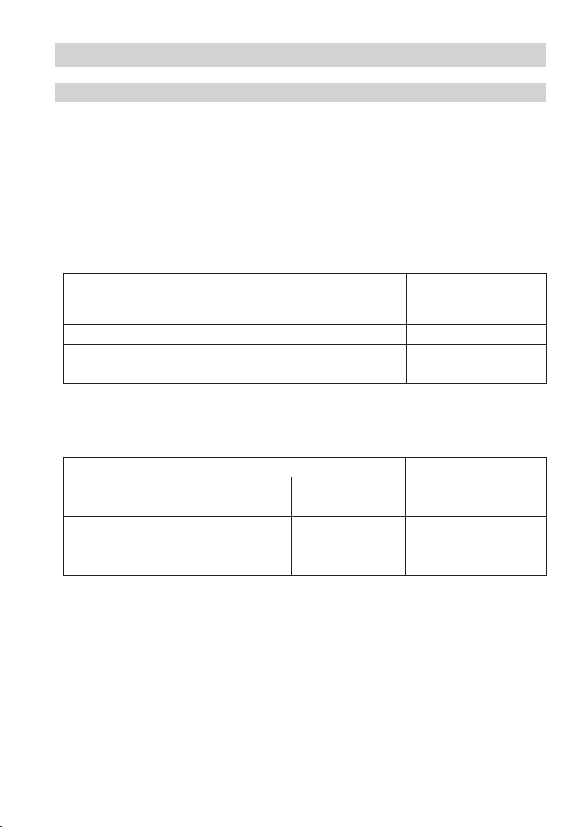
Table Fig. 3 shows the dependence of the Safety Integrity Level (SIL) on the average probability of failure
on demand of a safety function for the whole safety-related system (PFD
is here considered for a water level limiter, which means that the frequency of demands for operation of
the safety-related system is no greater than one per year.
). The “Low demand mode”
sys
Low demand mode PFD
-5
... < 10
≥ 10
-4
... < 10
≥ 10
-3
... < 10
≥ 10
-2
... < 10
≥ 10
Safety Integrity Level
sys
-4
-3
-2
-1
(SIL)
4
3
2
1
Fig. 3
The table in Fig. 4 indicates the attainable Safety Integrity Level (SIL) as a function of the Safe Failure
Fraction (SFF) and the Hardware Fault Tolerance (HFT) for safety-related systems.
Hardware Fault Tolerance (HFT) for type B
0 1 2
SIL 1 SIL 2
SIL 1 SIL 2
SIL 2
SIL 3 SIL 4 90 % – < 99 %
SIL 3 60 % – < 90 %
SIL 3 SIL 4 SIL 4 ≥ 99 %
Safe Failure Fraction
(SFF)
< 60 %
Fig. 4
7
Page 8

8
Technical Data
NRS 1-51
Supply:
Mains voltage
24 VDC +/– 20%, 0.3 A or 100 – 240 VAC +10/–15 %, 47 – 63 Hz, 0.2 A
External fuse
0.5 A (semi-delay)
Power consumption
7 VA
Inputs:
Electrical connection of level electrode
1 input for level electrode NRG 1...-51, NRG 1...-12, 4-poles with screen
Sensitivity 0.5 μS/cm or 10 μS/cm (at 25 °C).
Stand-by input
1 volt-free input, 18-36 VDC, for monitoring the purging and bypass time.
Max. bypass time: 5 minutes.
Outputs:
Control circuit
2 volt-free make contacts, 24 V DC – 250 V AC, max. 6 A (resistive/inductive),
Contact material AgNi.
Delay of response: 3 seconds.
Provide inductive loads with RC combinations according to manufacturer's specification to ensure
interference suppression.
Signal output
1 volt-free output for instantaneous external signalling, 24 – 230 V AC/DC, max. 100 mA.
Indicators and adjustors
2 buttons for test and diagnosis,
2 red/green LEDs for indicating the operating mode and alarm.
3 red LEDs for diagnosis.
Housing
Housing material: base: polycarbonate, black; front: polycarbonate, grey.
Cross section of connection: 1 x 4.0 mm
1 x 2.5 mm
2 x 1.4 mm
2
per stranded wire with sleeve to DIN 46228 or
2
per stranded wire with sleeve to DIN 46228; terminal strips can be detached
2
solid per wire or
Fixing of housing: Mounting clip on supporting rail TH 35, EN 60715
Electrical safety
Degree of contamination: 2, overvoltage category III to EN 61010-01.
Protection
Housing: IP 40 to EN 60529
Terminal strip: IP 20 to EN 60529
Weight
approx. 0.5 kg
Page 9

Technical Data – continued –
NRS 1-51 – continued –
Further conditions:
Water quality
(max. admissible electrical conductivity of the boiler water)
steam boiler plants / (pressurised) hot-water installations < 10000 µS/cm (at 25 °C)
Ambient temperature
when system is switched on: 0 ... 55 °C
during operation: –10 ... 55 °C
Transport temperature
–20 ... +80 °C (< 100 hours), defrosting time of the de-energized equipment before it can be put into
operation: 24 hours.
Storage temperature
–20 ... +70 °C, defrosting time of the de-energized equipment before it can be put into operation:
24 hours.
Relative humidity
max. 95%, no moisture condensation
Site altitude
max. 2000 m
Approvals
EC Prototype approval PED Pressure Equipment Directive 97/23/EC
EN 12952-11, EN 12953-09: Requirements made on
limiting equipment for boilers.
Functional safety IEC 61508 Functional safety of safety-related electrical/
SIL 3 electronic/programmable electronic systems
TÜV type approval VdTÜV Bulletin “Wasserstand 100” (= Water Level 100):
Requirements made on water level limiting & control equipment.
Type approval no. TÜV · SWB / SHWS · XX-XXX
(see name plate)
9
Page 10

10
Technical Data – continued –
24V =
+ / - 20%
NL
(+)
M 0,5A
(-)
NRS 1 - 51
Tamb = 55°C (131°F)
IP 40 (IP20)
7 VA
Betriebsanleitung
beachten
See installation
instructions
Voir instructions de
montage
Alarm
extern
24-230 VAC/DC
100 mA
0525
250V
T 2,0A
TÜV . SWB/SHWS . 09-...
GESTRAAG
Münchener Str.77
D-28215 Bremen
Niveauschalter
Level switch
Commutateur de niveau
20 21
N L
1. / 2.
3sec.
6 7
Funktionale Sicherheit
Functional safety
Sécurité fonctionnelle
IEC 61508
SIL 3
10 µS/cm
2
NRG 1...-51
1
2
3
1
3
4
5
16
17
232426
27
NRS 1-51
MAX
SRL
+
-
Hochwasserstandsicherung
High water level limiter
Limiteur de niveau d’eau haut
Name plate / marking
Safety
note
Type
designation
Mains voltage/
Protection
Ambient
temperature /
sensitivity
Wiring
diagram
Manufacturer
Fig. 5
Wire link,
provided on site
Control
circuit
Fuse, provided
on site
Approvals
Disposal
note
Page 11

Dimensions and Functional Elements
NRS 1-51
6
100
73
7
1
2
3
Fig. 6
Key
1 Upper terminal strip
2 Lower terminal strip
3 Fixing screws (cross recess head screws M3)
6 Enclosure
7 Supporting rail type TH 35, EN 60715
118
11
Page 12

12
Important Notes
Safety note
High water level alarms are safety devices and must only be installed, wired and commissioned by
qualified and competent staff.
Retrofitting and maintenance work must only be performed by qualified staff who – through adequate
training – have achieved a recognised level of competence.
Danger
The terminal strips of the NRS 1-51 are live during operation.
This presents the danger of electric shock!
Always cut off power supply to the equipment before mounting, removing or connecting
the terminal strips!
Attention
The name plate specifies the technical features of the equipment. Note that any piece of
equipment without its specific name plate must neither be commissioned nor operated.
Scope of supply
NRS 1-51
1 Level switch NRS 1-51
1 Installation manual
Page 13

Installation
Mounting level switch NRS 1-51
The level switch NRS 1-51 is clipped onto the support rail
cabinet. Fig. 6
7 type TH 35, EN 60715 in the control
Electrical Connection
Mains supply
Provide the level switch NRS 1-51 with an external semi-delay fuse 0.5 A.
Connection of level electrode
To connect the level electrode use screened multi-core control cable with a min. conductor size
0.5 mm2, e.g. LiYCY 4 x 0.5 mm2 .
Max. length 100 m with an electrical conductivity of the boiler water > 10 μS/cm at 25 °C.
Max. length 30 m with an electrical conductivity of the boiler water < 10 μS/cm at 25 °C.
Wire terminal strip in accordance with the wiring diagram. Fig. 5.
Connect screens only to terminal 5.
Connection of control circuit
Connect the control circuit for the feedwater supply / heating to terminals 23, 24 and 26, 27. Wenn
used as high water level alarm to TRD, EN 12952 / EN 12953 connect the output contacts of both
monitoring channels by fitting a wire link between the terminals 24 and 26.
Fuse the output contacts with a 2 A or 1 A (for 72 hours operation acc. to TRD 604) slow-blow fuse.
Note
n A high level alarm prevents the water level from exceeding the preset max. liquid
level (HW). For this purpose it can, for instance, interrupt the feedwater supply. If the
interruption of the feedwater supply endangers the heating surfaces in the feedwater
preheater (economizer), the heating must be switched off, too.
n In the event of an alarm the level switch NRS 1-51 does not interlock automatically.
If a lockout function is required by the installation it must be provided in the follow-up
circuitry (control circuit). The circuitry must meet the requirements of the EN 50156.
Connection of logic unit (standby input)
For connecting the level switch with the logic unit use a control cable, e. g. 2 x 0.5 mm2.
The control voltage must not exceed 36 V DC.
13
Page 14

14
Electrical Connection – continued –
Connection for signal output
A signal output for the connection of external signalling equipment is allocated to the monitoring
channel in the level switch, max. load 100 mA. For connecting the level switch with the logic unit use
a control cable, e.g. 2 x 0.5 mm
(terminals 20, 21) closes instantaneously.
Danger
n For the supply of the level switch NRS 1-51 with 24 V DC use a safety extra-low
voltage (SELV) power supply unit that must be electrically isolated from dangerous
contact voltages and must meet at least the requirements on double or reinforced isolation acc. to DIN EN 50178 or DIN EN 61010-1 or DIN EN 60730-1 or DIN EN 60950
(safe electrical isolation).
n Any item of equipment that you want to connect to terminals 6, 7 (standby input 1)
must be certified to have at least double or reinforced isolation according to DIN
EN 50178 or DIN EN 61010-1 or DIN EN 60730-1 or DIN EN 60950 (safe electrical
isolation) between the standby inputs and the live parts of the installation that are not
supplied with safety extra-low voltage (SELV).
Attention
n Fuse the level switch NRS 1-51 with an external semi-delay fuse 0.5 A.
n Connect screens of electrode wires only to terminal 5.
n To protect the switching contacts fuse the safety circuit with a slow-blow fuse 2 A or 1
A (for 72 hrs. operation acc. to TRD 604).
n When switching off inductive loads, voltage spikes are produced that may impair the
operation of control and measuring systems. Connected inductive loads must be provided with suppressors such as RC combinations as specified by the manufacturer.
n When used as high water level alarm according to TRD, EN 12952 / EN 12953 connect
terminals 24 and 26 by fitting a wire link.
n Install connecting lines to level electrodes and logic unit separated from power cables.
n Do not use unused terminals as support point terminals.
2
. In the event of an alarm or error message the signal output
Tools
n Screwdriver for slotted screws, size 3.5 x 100 mm, completely insulated according to VDE 0680-1.
Page 15

2716
1 2 3 4 5 6 7 8
17 18 19 20 21 22 23 249251026
11 12281329143015
NRG 1...-51
1
2
3
+ -
M 0,5A
Electrical Connection – continued –
Wiring diagram for level switch NRS 1-51
L N
8
(+) (-)
9 0
0
M 0.5A
a
b
Fig. 7
Key
c
8 Mains supply
9 Signal output 1 for external alarm 24-230 V AC/DC 100 mA
0 Control circuit, input and output
a Wire link, fitted on site, when used as high water level alarm acc. to TRD, EN 12952 / EN 12953
b Stand-by input 1, 24 V DC, for connecting the logic unit SRL 6-50
c Level electrode NRG 1...-51, NRG 1...-12
15
Page 16

16
Electrical Connection – continued –
Schematic representations of arrangements
d
e
f
Fig. 8
Key
Steam boiler plants according to TRD 604, EN 12952-07 / EN 12953-06, 72 h operation
Fig. 8
Combination consisting of 1 level electrode NRG 1...-51 and 1 level switch NRS 1-51 as high water level
alarm. Functional safety IEC 61508, SIL 3.
Further applications in accordance with national sets of regulations
Fig. 9
Combination consisting of 1 level electrode NRG 1...-51 and 1 level switch NRS 1-51 as high water level
alarm
. The level switch opens two separate control circuits. Functional safety IEC 61508, SIL 3.
d
e
f
Fig. 9
d Level electrode(s) NRG 1...-51
e Level switch NRS 1-51
f Control circuit
Basic Settings
Factory setting
Level Switch NRS 1-51
The level switch features the following factory set default values:
n De-energizing delay: 3 sec.
Page 17

Commissioning Procedure
Checking switchpoint and function
Level electrode 1
Test & diagnosis
button
LED alarm 1 /
Fig. 14
Activity Indication Function
Apply mains voltage.
Lower water level in boiler
until the level falls below
the switchpoint high water
level (HW). Level electrode is
exposed.
Raise level in boiler until the
switchpoint “high water level
(HW)” is ecxeeded. Level
electrode enters the water.
operating mode
Diagnosis LED
All LEDs are illuminated.
All LEDs are illuminated for more
than 10 sec.
Green LED
for level electrode 1 is illuminated
Checking switchpoint and function
Red LED
for level electrode 1 is flashing
Red LED
for level electrode 1 is illuminated
Start
System is being started and tested, this takes
approx. 10 sec. Output contacts are open.
Signal output 1 closed.
System malfunction. Possible causes:
Faulty power supply, level switch defective.
Output contacts are closed.
Signal output 1 is open.
De-energizing delay is running.
Signal output 1 is closed instantaneously.
Delay time has elapsed, output contacts open.
Signal output 1 is closed.
Possible installation faults
Status and indication Fault Remedy
Replace electrode rod and cut new rod to the
length dictated by the switchpoint HW.
Clean seating surfaces and screw in level
electrode with metallic joint ring. Do not
insulate the electrode with hemp or PTFE
tape!
Set response sensitivity of the level switch to
0.5 μS/cm.
Check installation of level electrode. Make
sure that the level in the protection tube corresponds to the actual water level.
Cut electrode rod to the length dictated by the
switchpoint HW.
Check installation of level electrode. Make
sure that the level in the protection tube
corresponds to the actual water level.
Sightglass indicates high
water level (HW) exceeded,red
LED for level electrode 1 is
not illuminated. Safety circuit
closed.
Water level sufficient. Red
LED for level electrode 1 is
illuminated. Safety circuit is
open.
The electrode rod is too short.
The earth connection to the vessel
is interrupted.
Electrical conductivity of the boiler
water too low.
If installed inside the boiler: Upper
vent hole in protection tube does
not exist or is obstructed.
Electrode rod is too long.
Upper vent hole flooded.
17
Page 18

18
Operation, Alarm and Test
Indicators and adjustors
Level electrode 1
Test & diagnosis
button
LED alarm 1 /
Fig. 14
Activity Indication Function
Level electrode exposed
Level electrode submerged,
high water level (HW)
exceeded.
During operation:
Press and hold down key 1
until the end of the test, level
switch must function as if there
were an alarm.
operating mode
Diagnosis LED
Green LED
for level electrode 1 is illuminated
Red LED
for level electrode 1 is flashing
Red LED
for level electrode 1 is illuminated
Red LED
for level electrode 1 is flashing
Red LED
for level electrode 1 is illuminated
Operation
Output contacts are closed.
Signal output 1 is open.
Alarm
De-energizing delay is running.
Signal output 1 is closed instantaneously.
Delay time has elapsed, output contacts open.
Signal output 1 is closed.
Test channel 1
Alarm simulated in channel 1 or 2.
De-energizing delay is running.
Signal output 1 is closed instantaneously.
Delay time has elapsed, output contacts open.
Signal output 1 is closed. Test finished.
Troubleshooting
Indication, diagnosis and remedy
Attention
Before carrying out the fault diagnosis please check:
Mains supply:
Is the level switch supplied with the mains voltage specified on the name plate?
Wiring:
Is the wiring in accordance with the wiring diagram and the relevant schematic
representation of arrangement?
Page 19

Troubleshooting – continued –
Indication, diagnosis and remedy – continued –
Malfunction in level electrode
Status and indication Fault Remedy
Water level sufficient. Red
LED for level electrode 1 is
illuminated. Safety circuit is
open.
Status Diagnosis Function Next activity
Faulty evaluation of level
electrode 1, channel 1
Malfunction in level
switch detected.
Display 1 and activity Display 2 Fault Remedy
LED alarm 1 and
diagnosis LED 1
illuminated. Press and hold
down key 1.
LED alarm 1 or 2
and Diagnosis LED 3
illuminated. Press and hold
down key 1 or 2.
Once the fault is eliminated, the level switch returns to normal operation.
After elimination of the fault switch off the mains voltage and switch it on again after approx. 5 sec.
The insulation of the level
electrode is dirty or faulty.
Further fault indications
Diagnosis LED 1 and
LED alarm 1 illuminated.
Diagnosis LED 3 and
LED alarm 1 or 2
illuminated.
Diagnosis
LED 1
flashing.
Diagnosis
LED 2
flashing.
Diagnosis
LED 3
flashing.
Diagnosis
LED 1
flashing.
Diagnosis
LED 2
flashing.
Diagnosis
LED 3
flashing.
Malfunction in level
electrode 1, malfunction in
level switch, faulty wiring,
faulty measuring voltage.
Malfunction in level
electrode 1, malfunction in
level switch, faulty wiring.
Interference voltage causing
malfunction, boiler earth
without PE
Malfunction in processor,
stand-by fault.
Internal voltage fault.
Malfunction in relay.
Clean or, if necessary, replace level electrode.
Output contacts are opened instantaneously.
Signal output 1 closes instantaneously.
Output contacts are opened instantaneously.
Signal outputs 1/2 are closed instantaneously.
Diagnosis
Check wiring,
replace level switch.
Provide screen and earthing, connect
boiler with PE.
Observe operating instructions for the
logic unit SRL. Replace level switch.
Replace level switch.
next:
Press key 1.
next:
Press key 1
or key 2.
If faults occur that are not listed above or cannot be corrected, please contact our service centre or
authorized agency in your country.
19
Page 20

20
Further Notes
Action against high frequency interference
Should sporadic failures occur in installations susceptible to faults (e. g. malfunctions due to out-ofphase switching operations) we recommend the following actions in order to suppress interferences:
n Provide inductive loads with RC combinations according to manufacturer's specification to ensure
interference suppression.
n Increase the distance to sources of interference.
n Check screens and shields.
n HF interference suppression by means of hinged-shell ferrite rings.
Interlock and interlock deactivation
In the event of an alarm the level switch NRS 1-51 does not interlock automatically.
If a lockout function is required by the installation it must be provided in the follow-up circuitry (control
circuit). The circuitry must meet the requirements of the EN 50156.
Checking the switchpoints
To check the switchpoint “High water level (HW) exceeded” you have to fill the boiler until the max.
water level is reached. As soon as the high level is reached the level switch must trigger an alarm and
open the control circuit after the de-energizing delay has elapsed The deactivation of the heating is
interlocked in the control circuit and the lockout can only be reset when the level electrode is exposed
again. Always check the switchpoint when commissioning the equipment, after replacing the level
electrode and at regular intervals, e. g. every year.
Decommissioning / replacing level switch
n Switch off mains voltage and cut off power supply to the equipment.
n Unscrew the right and left fixing screws 3 and remove the upper and lower terminal strips 1 2,
Fig. 6
n Undo the fixing slide in order to snap out the level switch and take it off the supporting rail.
Disposal
Remove the level switch and separate the waste materials in accordance with the material
specification.
Electronic component parts such as the circuit board must be disposed of separately!
For the disposal of the levels switch observe the pertinent legal regulations concerning waste disposal.
Note on the Declaration of Conformity / Declaration by the Manufacturer
For details on the conformity of our equipment according to the European Directives see our
Declaration of Conformity or our Declaration of Manufacturer.
The current Declaration of Conformity / Declaration of Manufacturer are available in the Internet under
www.gestra./de/documents or can be requested from us.
Page 21

For your Notes
21
Page 22

22
For your Notes
Page 23

For your Notes
23
Page 24

Agencies all over the world:
www.gestra.de
GESTRA
España
GESTRA ESPAÑOLA S.A.
Luis Cabrera, 86-88
E-28002 Madrid
Tel. 0034 91 / 5 15 20 32
Fax 0034 91 / 4 13 67 47; 5 15 20 36
E-mail: aromero@flowserve.com
Great Britain
Flowserve GB Limited
Abex Road
Newbury, Berkshire RG14 5EY
Tel. 0044 16 35 / 46 99 90
Fax 0044 16 35 / 3 60 34
E-mail: gestraukinfo@flowserve.com
Italia
Flowserve S.p.A.
Flow Control Division
Via Prealpi, 30
l-20032 Cormano (MI)
Tel. 0039 02 / 66 32 51
Fax 0039 02 / 66 32 55 60
E-mail: infoitaly@flowserve.com
Polska
GESTRA POLONIA Spolka z.o.o.
Ul. Schuberta 104
PL - 80-172 Gdansk
Tel. 0048 58 / 3 06 10 - 02
0048 58 / 3 06 10 - 10
Fax 0048 58 / 3 06 33 00
E-mail: gestra@gestra.pl
Portugal
Flowserve Portuguesa, Lda.
Av. Dr. Antunes Guimarães, 1159
Porto 4100-082
Tel. 00351 22 / 6 19 87 70
Fax 00351 22 / 6 10 75 75
E-mail: jtavares@flowserve.com
USA
Flowserve GESTRA U.S.
2341 Ampere Drive
Louisville, KY 40299
Tel. 001 502 / 267-2205
Fax 001 502 / 266-5397
E-mail: FCD-Gestra-USA@flowserve.com
GESTRA AG
P. O. Box10 54 60, D-28054 Bremen
Münchener Str. 77 , D-28215 Bremen
Telephone 0049 (0) 421 / 35 03- 0
Fax 0049 (0) 421 / 35 03 - 393
E mail gestra.ag@flowserve.com
Internet www.gestra.de
818955-01/12-2009cm (808806-01) · GESTRA AG · Bremen · Printed in Germany
24
 Loading...