

Page 1

NRR 2-40
Installation Instructions 810369-03
Level Controller Type NRR 2-40
1
Page 2

Contents
Page
Important Notes
Usage for the intended purpose ..................................................................................... 7
Safety note / Warning ...................................................................................................... 7
Explanatory Notes
Scope of supply ..............................................................................................................8
System description ......................................................................................................... 8
Function ..........................................................................................................................8
Technical data ................................................................................................................ 9
Installation
NRR 2-40 ......................................................................................................................10
Example of installation .................................................................................................35
Wiring
Wiring diagram............................................................................................... 3, 4, 10, 11
Basic Adjustments
CAN bus........................................................................................................................ 12
Node ID .........................................................................................................................12
Factory setting ..............................................................................................................13
Controller NRR 2-40 .....................................................................................................13
Commissioning
NRR 2-40 ......................................................................................................................14
Control range ................................................................................................................14
Adjusting the control range.................................................................................... 14, 15
Establishing switchpoints and proportional band .................................................. 16–19
Calibrating the feedback potentiometer of an external control valve .......................... 20
Operation
Normal operation ..........................................................................................................21
Alarm / High-level alarm / Low-level alarm .................................................................. 21
Relay test high/low level alarm ....................................................................................22
System Malfunctions
Systematic fault finding prodedure ...............................................................................23
System malfunctions 1 to 4 ................................................................................... 24–26
Operation Malfunctions
Fault-finding list for troubleshooting ...................................................................... 26–27
Annex
Factory set default node ID ................................................................................... 28, 29
Assigning/changing node ID......................................................................................... 28
Neutral band .................................................................................................................30
Establishing / changing neutral band .................................................................... 30–32
Declaration of conformity.............................................................................................. 34
2
Page 3
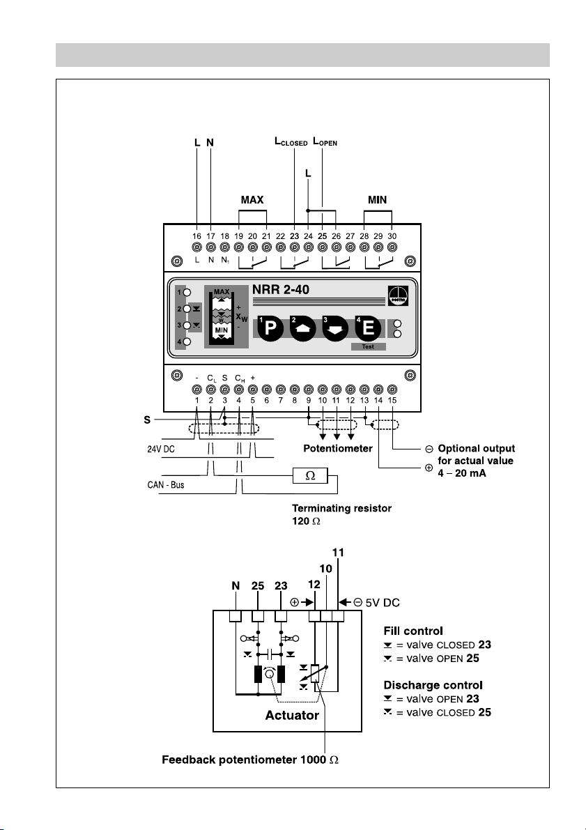
Wiring Diagram
NRR 2-40 as three-position stepping controller
Paired cable
Paired cable
Fig. 1
Fig. 2
3
Page 4
Wiring Diagram
NRR 2-40 as continuous controller
Paired cable
Paired cable
Fig. 3
Control terminal
and display unit
URB 1
Terminating resistor
120 Ω
*) CEP = central earthing point
Level switch
NRS 1-42
CEP*)
Voltage supply CAN data line
Fig. 4
4
Level controller
NRR 2-40
Level electrode
NRG16-42
Terminating resistor
120 Ω
Sensor
...
Page 5
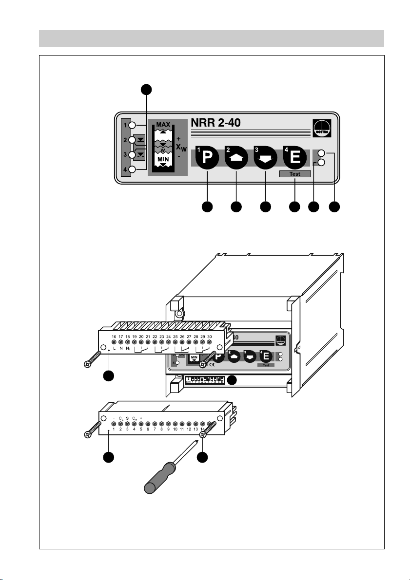
Parts Drawings
1
Fig. 5
7
6
A
A
B
8
5
234
Fig. 6
5
Page 6

Key
Indicator LED
1
LED 1 – Switchpoint 1
LED 2 – Control valve closing
LED 3 – Control valve opening
LED 4 – Switchpoint 4
LED “Bus status”
2
LED “Power”
3
Enter button / Test mode
4
Decrease button
5
Increase button
6
7
Program button
Code selector switch, 10 poles
8
A
Terminal strip
B
Screws for terminal strip
High-level
not allocated
not allocated
Low-level
MalfunctionAlarm
Multifunction
Multifunction
Multifunction
Multifunction
6
Page 7
Important Notes
Usage for the intended purpose
Use level controller NRR 2-40 in combination with level electrode NRG 26-40 only
for controlling the liquid level of conductive fluids.
Safety Note
The equipment must only be installed by qualified staff.
Qualified staff are those persons who – through adequate training in electrical
engineering, the use and application of safety equipment in accordance
with regulations concerning electrical safety systems, and first aid & accident
prevention – have achieved a recognised level of competence appropriate
to the installation and commissioning of this device.
Warning
The terminal strip of the NRR 2-40 is live during operation. This presents
the danger of electric shock. Cut off power supply before fixing or
removing the housing lid or terminal strips.
7
Page 8

Explanatory Notes
Scope of supply
NRR 2-40
1 Level controller type NRR 2-40 (plug-in unit in plastic case with box terminals)
1 Terminating resistor 120 Ω
1 Installation manual
System Description
Use level controller type NRR 2-40 in combination with level electrode type
NRG 26-40 for level control and monitoring. The level controller has the following
functions:
■
Two liquid level limits with one switchpoint each (HIGH-LEVEL alarm, LOW-LEVEL
alarm)
■
Three-position stepping or modulating control within a predefined proportional
band
■
Continuous level monitoring within the control band defined by two preset limits
The NRR 2-40 features an optional output for a standard signal 4 – 20 mA.
The level data are transferred from the electrode NRG 26-40 to the level controller
via a CAN data bus.
Function
At regular intervals the level electrode NRG 26-40 sends a data telegram to the level
controller NRR 2-40. The data are transferred via a CAN bus to DIN ISO 11898,
adopting the CANopen protocol. The transmitted data are then evaluated and
allocated to the manually adjusted switchpoints. Optionally a standard signal
4 – 20 mA is established for external level indication. A relay de-energizing delay
can be set manually with the control terminal and display unit URB 1.
To guarantee the correct functioning and safety of the system the data transmitting
cycle of the level controller is constantly monitored. When the CAN bus line is
interrupted the level controller sends a visual signal to indicate a malfunction and the
relays 1 and 4 will be instantaneously de-energized (alarm position).
GESTRA’s control terminal and display unit URB 1 enables advanced features such
as adjustable energizing and de-energizing delays of the output relays (1– 25 s).
8
Page 9

Technical Data
Type approval no.
NRR 2-40: TÜV
.
98-399
Input / Output
Interface for CAN bus to DIN ISO 11898 CANopen
Feedback potentiometer 1000Ω
Output – voltage supply for electrodes
Power supply 24V DC, short-circuit protected.
Analogue output 4– 20 mA, load 500Ω for display of actual value (option).
Analogue control output for manipulated variable 4– 20 mA, max. load 500Ω (option).
4 volt-free relay contacts.
Max. contact rating with switching voltages of 24V AC, 115V AC and 230 V AC:
4 A resistive, 0.75 A inductive at cos ϕ 0.5
Max. contact rating with a switching voltage of 24V DC: 4 A.
Contact material: silver, hard-gold plated
Interference suppression
Provide contactor with an external RC combination (100 Ω / 47 nF)
Relay de-energizing delay
Output “
MIN”, “MAX” 3s
Indicators and adjustors
1 red LED for switchpoint “
1 red LED for switchpoint “
2 green LEDs for “
1 green LED “
1 red LED “
CONTROL VALVE OPENING” and “CONTROL VALVE CLOSING”
OPERATION”
BUS MALFUNCTION”
MAX”
MIN”
1 ten-pole code selector switch for setting node ID and baud rate
4 pushbuttons
Proportional band X
p
1 % to 100%
Valve position feedback
0 Ω to 1000 Ω (only when used as three-position stepping controller)
Switching range (dead band) X
Sh
0 % (factory setting) up to 15 %
Supply voltage
230 V ± 10 %, 50/60 Hz
115 V ± 10 %, 50/60 Hz (option)
Power consumption
10 VA
Protection
Case: IP 40 to DIN ISO 60529
Terminal strip: IP 20 to DIN ISO 60529
Admissible ambient temperature
0 °C to 55 °C
Case material
Front panel: polycarbonate, grey
Enclosure: polycarbonate, black
Weight
Approx. 0.8 kg
9
Page 10
Installation
NRR 2-40
Installation on mounting rail
1. Clip level controller onto mounting rail 35x 15 mm (DIN EN 50022).
2. Align level controller, fig. 19, 20.
Tool
■ Screwdriver (5.5/100)
Wiring
Note that screened multi-core twisted-pair control cable is required, e. g.
UNITRONIC
®
BUS CAN 2 x 2 x ... 2 or RE-2YCYV-fl 2 x 2 x ... 2.
The baud rate (data transfer rate) dictates the cable length between the bus nodes
and the total current consumption of the measuring sensors dictates the conductor
size.
8S9S01SetarduaBhtgnelelbaC
FFO NO FFO s/tiBk052 m521
gnittesyrotcaF
NONOFFOs/tiBk521m0525.0x2x2
FFOFFONOs/tiBk001m53357.0x2x2
NOFFONOs/tiBk05m005
FFONONOs/tiBk02m0001
NONONOs/tiBk01m0001
sriapforebmuN
2
mm[ezisrotcudnocdna
]
43.0x2x2
notnedneped,tseuqerno
noitarugifnocsub
The baud rate is set via a code switch. Reduce baud rate if cable is longer than
specified in the table. Make sure that all bus nodes have the same settings.
To protect the switching contacts fuse circuit with 2.5 A (anti-surge fuse) or according
to TRD regulations (1.0 A for 72 hrs operation).
When a max. cable length of 1000 m is desired, make sure to modify the baud
rate accordingly. Refer to pages 28 and 29 for more details.
Wiring diagram
See wiring diagrams on pages 3 and 4.
UNITRONIC® is a registered trademark of LAPP Kabelwerke GmbH, Stuttgart
10
Page 11
Wiring – continued –
Attention
■
Wire equipment in series. Star-type wiring is not permitted.
■
Interlink screens of control cables such that electrical continuity is
ensured and connect them once to the central earthing point (CEP).
■
To protect the switching contacts fuse circuit with 2.5 A (slow blow) or
according to TRD regulations.
■
If more than one system components are connected to a CAN bus
network provide the first and last equipment with a terminating
resistor of 120 Ω. Fig. 4
■
The CAN bus network must not be interrupted while operating.
Any interruption will result in
If the level controller must be replaced, remove terminal
strip Fig. 6.
Before removing the CAN-bus line from the terminal strip disconnect all
relevant system components to avoid malfunction alarms.
Note
■
Connect screen only to designated terminals.
■
The loop resistance must be under 10 Ω.
■
The rated voltage is stated on the name plate.
■
When switching off inductive loads, voltage spikes are produced that
may impair the operation of control and measuring systems. Inductive
loads should therefore be provided with commercial arc suppressor
RC combinations.
■
In spite of correct wiring H.F. interference caused by the installation
may lead to system breakdowns and malfunction messages. If
necessary refer to the “Fault finding list for troubleshooting” on
pages 26 and 27.
HIGH/LOW level alarm!
A
Tool
■ Screwdriver for slotted screws, size 2.5, completely insulated according to
VDE 0680.
11
Page 12

Basic Adjustments
CAN bus
All level and conductivity controllers and associated electrodes are interconnected
by means of a CAN bus using the CANopen protocol. Every item of equipment
features an electronic address (node ID). The four-core bus cable serves as power
supply and data highway for high-speed data exchange.
The CAN address (node ID) can be set between 1 and 123.
The NRR 2-40 is configured at our works and ready for service with other GESTRA
system components without having to set the node ID.
If several systems of the same kind are to communicate in one CAN bus
network, be sure to assign one node ID for each individual system component.
Refer to pages 28 and 29 for more details.
Node ID
12
Page 13

Basic Adjustments – continued –
Factory setting
The level controller features the following factory set default values:
■ Baud rate: 250 kb/s
■ Proportional band X
■ Node ID: 040
■ Switchpoint 1: 80 %
■ Switchpoint 4: 20 %
: 20%
P
■ Relay with de-energizing delay switchpoint 1: 3s
■ Relay with de-energizing delay switchpoint 4: 3s
80 %
60%
40 %
20 %
100%
20 %
0%
Fig. 7
Controller NRR 2-40
The controller type NRR 2-40 is specially designed for level control in steam boilers
and feedwater deaerators. The NRR 2-40 is a proportional controller with steadystate deviation. The positive and negative deviation lies within the proportional band
(Xp) preselected by the user.
It is possible to control electric and pneumatic actuators. The control of electric
actuators is accomplished by an analogue signal which, in combination with an
active position feedback coming from the valve, is converted in the controller into a
three-position stepping signal. The control pulses for the electric actuator are
transmitted by a relay incorporated in the controller.
The control of pneumatic actuators is effected by an analogue signal 4– 20 mA.
The analogue signal is transmitted directly from the proportional controller to the
positioner of the pneumatic control valve, which means that an active position
acknowledgement is not possible.
X
values:
P
X
> large permanent deviation, valve reacts sluggishly
P
X
< no permanent deviation, valve may be hunting
P
recommended X
value 30 % – 100 %.
P
13
Page 14

Commissioning
NRR 2-40
Apply power to the unit.
The four indicator LEDs flash rapidly.
The LED “Power” lights up.
The test cycle takes about two seconds.
Control Range
Desired control range [mm]
Max. control range
Indicator LEDs flash rapidly
LED “Power” illuminated.
Determine the appropriate level
control range for your
system.
Fig. 8
Adjusting the control range
Press button for 3 sec.
Lower liquid level until the lower limit of
the control range is reached.
If necessary first use button to
adjust the upper limit of the control
range.
Press button briefly.
Note:
In the event of a system malfunction, the
LED(s) “Bus status” and/or “Power” will
be flashing rapidly when in program
mode. Quit program mode and
analyse the system malfunction
(see pages 22 – 26).
14
NRG 26-40
37
Lower measuring point
26
LEDs illuminated LEDs flash slowly
3 sec.
LEDs flash LEDs flash rapidly
briefly
LED “Power”
Page 15

Commissioning – continued –
Adjusting the control range – continued –
Press button briefly.
The lower limit of the desired control
range is now saved.
LEDs illuminated LEDs flash slowly
briefly
Press button briefly.
Raise liquid level until the desired upper
limit of the control range is reached.
Press button briefly.
Press button twice briefly.
The upper limit of the desired control
range is now saved.
The NRR 2-40 is now again in operating
mode.
LEDs illuminated LEDs flash slowly
briefly
LEDs illuminated LEDs flash slowly
briefly
twice briefly
15
Page 16

Commissioning – continued –
Switchpoints and proportional band
Switchpoint 1
Switchpoint 2
Switchpoint 3
Switchpoint 4
Selected control range
You can establish two switchpoints and a proportional band Xp within the control
range.
X
P
NRG 26-40
Fig. 9
16
80 %
70%
50 %
20 %
20%
90 %
45%
35 %
10 %
Fig. 10 (example) Fig. 11 (example)
10%
Page 17

Commissioning – continued –
Establishing switchpoints and proportional band
Press button briefly.
Raise or lower the liquid level in the
vessel until the desired value is reached.
Use button if you first want to
establish the proportional band or a
different switchpoint.
LED illuminated LEDs flash slowly
briefly
Press button briefly.
Lower the liquid level until switchpoint 4
within the desired control range is reached.
Note:
In the event of a system malfunction,
the LED(s) “Bus status” and/or “Power”
will be flashing rapidly when in program
mode.
Press button briefly.
Switchpoint 4 is now saved.
Press button briefly.
The lower limit of the proportional band
X
is now selected (switchpoint 3).
p
LED flashes LEDs flash slowly
briefly
LED illuminated LEDs flash slowly
briefly
LED illuminated LEDs flash slowly
briefly
Press button slowly.
Raise the liquid level until switchpoint 3
within the desired control range is reached.
Example:
Liquid level switchpoint 3 = 40% and
liquid level switchpoint 2 = 60% make a
proportional band X
The setpoint is at approx. 50%.
(60% – 40 %) = 20 %
p
LED flashes LEDs flash slowly
briefly
17
Page 18

Commissioning – continued –
Establishing switchpoints and proportional band – continued –
Press button briefly.
Switchpoint 3 is now saved.
LED illuminated LEDs flash slowly
briefly
Press button briefly.
The upper limit of the proportional band
X
is now selected (switchpoint 2).
p
Press button briefly.
Raise liquid level until switchpoint 2
within the desired control range is
reached.
Example:
Liquid level switchpoint 3 = 40% and
liquid level switchpoint 2 = 60% make a
proportional band X
of 20%.
p
Press button briefly.
Switchpoint 2 is now saved.
LED illuminated LEDs flash slowly
briefly
LED flashes LED flash slowly
briefly
LED illuminated LEDs flash slowly
briefly
Press button briefly.
Switchpoint 1 is now selected.
18
LED illuminated LEDs flash slowly
briefly
Page 19

Commissioning – continued –
Establishing switchpoints and proportional band – continued –
Press button briefly.
Raise liquid level until switchpoint 1
within the desired control range is
reached.
LED flashes LEDs flash slowly
briefly
Press button twice briefly.
Switchpoint 1 is now saved.
The NRR 2-40 is now again in operating
mode.
LED illuminated
twice briefly
19
Page 20

Commissioning – continued –
Calibrating the feedback potentiometer of an external control valve
The feedback potentiometer of an external control valve with electric actuator has to
be manually calibrated before commissioning.
1. Ascertain the total resistance of the feedback potentiometer.
2. Set the control valve manually into mid-position.
3. Adjust manually the position of the feedback potentiometer until the partial
resistance values of the measured total resistance are equal.
Fig. 12
Attention
20
■ The GESTRA level controller type NRR 2-40 requires a 1000
feedback potentiometer.
■ The NRR 2-40 works as two-position controller when the terminals for
the feedback potentiometer are not wired or the feedback potentiometer
is defective.
■ Use the control and display unit URB 1 for semi-automatic calibration of
the feedback potentiometer of an external control valve without
measurement of the resistance value. For more details see the
installation instructions of the URB 1.
ΩΩ
Ω
ΩΩ
Page 21

Operation
Normal operation
Normal operation, controller is working.
The green LEDs 2 and 3 flash when the
external control valve is opened or
closed.
All LEDs go out when the setpoint is
reached.
The LED “Power” is illuminated.
Alarm
There are two types of alarm:
■ High-level alarm
■ Low-level alarm
High-level alarm
LED 1 changes after the de-energizing
delay from rapid flashing to lighting.
Low-level alarm
LEDs flash when the control valve is motored
LED “Power” illuminated
illuminatedflashes
LED 4 changes after the de-energizing
delay from rapid flashing to lighting.
flashes illuminated
21
Page 22

Operation – continued –
Relay test high/low-level alarm
Press button briefly.
The test mode is active for 5 seconds.
LEDs illuminated
briefly
Hold down button .
Indicator LED 4 goes out
LED 4 goes out.
A low-level alarm is simulated for
switchpoint 4.
Hold down button .
Indicator LED 1 goes out
LED 1 goes out.
A high-level alarm is simulated for
switchpoint 1.
System Malfunctions
There are four types of system malfunctions that might occur in the level electrode
and the level controller:
■ Max. admissible temperature in electrode terminal box exceeded
■ No or faulty communication between controller and electrode
■ Malfunction in CAN bus
■ Failure of 24 V power supply unit built in level controller NRR 2-40
22
Attention
The terminal strip of the NRR 2-40 is live during operation.
This presents the danger of electric shock.
Cut off power supply before mounting or removing the equipment.
Page 23

System Malfunctions – continued –
Systematic Malfunction Analysis
The sources of malfunctions occurring in CAN bus systems operating with several
bus-based stations must be analysed systematically since faulty components or
incorrect settings can give rise to negative interactions with intact bus devices in
the CAN bus system. These unwanted interactions can cause error messages in
fully functional bus devices, which will make fault detection even more difficult.
We recommend the following systematic fault finding procedure:
Step 1 (Start)
Detach terminal strips
in all sensing units of
bus nodes.
Level electrode
Conductivity electrode
Pressure sensor
Temperature sensor
Check
Use fault-finding
list to correct
fault(s).
Final test:
have all faults
been eliminated?
System
Malfunction
Use fault-finding list
to identify the
fault(s).
Cut off power supply
to the equipment.
Step 2
Plug in terminal strips
of the bus nodes
e. g.
NRS ...
and
NRG ...
(sensing unit)
Step 3
Apply mains voltage
to bus nodes,
e. g.
NRS ...
and
NRG ...
Check next system
System O.K.
Detach terminal
strips between
bus nodes
e. g.
NRS ...
and
NRG ...
23
Page 24

System Malfunctions – continued –
System malfunction 1
The four indicator LEDs flash slowly.
High/low-level alarm
LEDs flash slowly
Fault:
Remedy:
The max. admissible temperature in the electrode terminal box is exceeded.
Insulate electrode flange to protect the equipment against heat radiation.
As soon as the temperature drops below the max. admissible limit the equipment
automatically returns to normal operation.
System malfunction 2
LEDs flash rapidly
The four indicator LEDs flash rapidly.
High/low-level alarm
Fault:
Remedy:
Fault:
Remedy:
The CAN bus line between the bus-based devices is interrupted.
Check wiring and terminals. Restart system.
Incorrect node ID(s).
Set correct nodes ID(s), referring to section “Annex - assigning and
changing the node IDs”. Disconnect the system from its power supply.
After 5 sec. apply power and restart system.
24
Page 25

System Malfunctions – continued –
System malfunction 3
LED “Bus status” flashes slowly.
Fault
: Malfunction in CAN bus.
Remedy:
LED “Bus status” flashes slowly.
High/low-level alarm
Restart system.
LED flashes slowly
LED flashes slowly
Fault:
Remedy:
Fault:
Remedy:
Fault
Remedy:
Data transfer in CAN bus interrupted.
The bus cables have to be correctly connected according to the wiring
diagram (observe polarity!). Make sure that all end-of-line devices are
provided with 120 Ω terminating resistors, see wiring diagram.
Disconnect the system from its power supply. After 5 sec. apply power
and restart system.
The baud rate of one or more bus-based devices is not set correctly.
Check baud rate settings of all bus devices. The baud rates must be
identical. Refer to section “Annex” for more details.
Disconnect the system from its power supply. After 5 sec. apply power
and restart system.
The overall length of the bus cable does not correspond to the selected
baud rate.
Change baud rate settings of all bus-based devices according to the
indications specified in “Annex”.
Disconnect the system from its power supply. After 5 sec. apply power
and restart system.
25
Page 26

System Malfunctions – continued –
System malfunction 4
LED “Power” flashes slowly.
LED flashes slowly
Fault:
Remedy:
Fault:
Remedy:
The power supply unit (PSU) is overloaded and may be misused for other
components.
Check load of power supply unit. Be sure to use the PSU only for the
voltage supply of bus-based network components.
Disconnect the system from its power supply. After 5 sec. apply power
and restart system.
Power supply unit defective.
Replace PSU.
Operation Malfunctions
Attention
The terminal strip of the NRR 2-40 is live during operation.
This presents the danger of electric shock.
Cut off power supply before mounting or removing the equipment.
Fault-finding list for troubleshooting
Device does not work – no function
Fault:
Remedy:
LED “Power” does not light up.
Apply power. Connect the equipment properly, referring to wiring
diagrams.
26
Page 27

Operation Malfunctions – continued –
Fault-finding list for troubleshooting – continued –
Device does not work – interference signal
Fault:
Remedy:
Device fails to function properly
In spite of correct wiring and commissioning of the equipment an
interference signal is indicated.
The interference signal is caused by high-frequency interferences coming
from the installation. For interference suppression we supply ferrite rings,
stock code # 147253. The 230 V supply lines should be looped five to ten
times through the ferrite ring. If several controllers are used in one
system, they can be fed from the interference suppressed supply lines.
For the interference suppression of the bus line we supply hinged-shell
ferrite rings, stock code # 147254. The hinged-shell ferrite rings are
clamped onto the bus line close to the terminal strip of the controller.
Fault:
Remedy:
Fault:
Remedy:
Fault
Remedy:
Fault:
Remedy:
Fault:
Remedy:
The device works as two-position controller
Fault:
Remedy:
Incorrect function at analogue output. The following actual value indicator
shows incorrect values.
Correct the switchpoint settings and the control range settings of the
electrode.
Switchpoints and actual value indication drift continuously towards 100%.
Deposits have accumulated on the electrode rod. Remove the level
electrode and clean the electrode rod.
A high-level alarm is raised although the liquid level is below high level.
Deposits have accumulated on the electrode rod. Clean the electrode rod.
Defective electrode insulation. Replace level electrode.
Liquid level below switchpoint “low level”, device fails to switch.
Check installation of level electrode and vent hole in the protection tube.
If an external measuring pot is used make sure to open the isolating
valves.
“High-level” switchpoint exceeded – no indication.
Level switch defective. Replace the equipment.
Feedback potentiometer defective or not connected.
Connect equipment according to wiring diagram. Check feedback
potentiometer.
If faults occur that are not listed above or cannot be corrected, please contact our
service center or authorized agency in your country.
27
Page 28

Annex
Warning
Ther terminal strip of the NRR 2-40 is live during operation. This presents
the danger of electric shock.
Cut off power supply before fixing or removing the housing lid or the
terminal strips.
Factory set default node IDs
Controller Level electrode
The node IDs of the individual units have to be adjusted manually.
For more information refer to the corresponding installations manuals.
Assigning/ changing node ID
If several systems of the same kind are to communicate in one CAN bus network, be
sure to assign one node ID for each individual system component (e. g. controller).
Detach terminal strip in order to set code switch .
Attention
■ Do not assign the same node ID twice within the CAN bus network.
A
8
Fig. 13
28
Page 29

Annex – continued –
Node ID
OFF
S1
OFFS2
OFFS3
ON
S4
OFFS5
ON
S6
OFFS7
Fig. 14 (Factory setting)
S8
OFF
S9 S0
ON
ONON
16
32
64
OFF
ON
ON
OFF 1000 m
ON
ONON
Fig. 16 (Factory setting 250 kBit/s)
ON
ON
ON
40
1
2
S1
S2
4
8
S4
S7
Fig. 15 (Example)
Baud rate
Cable length
250 kBit/s
125 kBit/s
100 kBit/sOFFOFF 335 m
50 kBit/sOFF
20 kBit/s
10 kBit/s
ON
ON
OFFS3
ON
OFFS5
OFFS6
ON
125 mOFF
250 m
500 m
1000 m
Node ID
1
2
4
8
16
32
64
75
29
Page 30

Annex – continued –
Warning
The terminal strip of the NRR 2-40 is live during operation.
This presents the danger of electric shock.
Cut off power supply before fixing or removing the housing lid or terminal
strips.
Neutral band
To guarantee a smooth controlled system you can establish a neutral band for the
setpoint W. The setpoint is defined by the proportional band which is determined by
switch point 2 and 3.
Detach terminal strip in order to set code switch .
A
Fig. 17 (Factory setting of neutral band)
Establishing/ changing neutral band
Note down current node ID and baud rate.
■ Node ID in this example “40”
■ Baud rate in this example
“
250 kBit/s”
8
Switch off mains voltage.
The four status LEDs go out.
The LED “Power” goes out.
30
LED “Power” extinguished
Page 31

Annex – continued –
Adjust neutral band according to fig. 18.
■ Neutral band in this example “2 %”
Apply mains voltage.
The four status LEDs flash rapidly. If the
LED “Power” is alight, the adjustment
was successful.
If the LED (“Bus status”) above the LED
“Power” is alight, repeat the adjustment
procedure.
Switch off mains voltage.
The four status LEDs go out.
The LED “Power” goes out.
Adjust current node ID and baud rate.
■ Node ID in this example “40”
■ Baud rate in this example
“
250 kBit/s”
Apply mains voltage.
The four status LEDs flash rapidly.
The LED “Power” is illuminated.
The system is ready for operation.
Status LEDs flash rapidly
LED “Power” illuminated
LED “Power” extinguished
Status LEDs flash rapidly
LED “Power” illuminated
31
Page 32

Annex – continued –
S1 S2 S3 S4 S5 S6 S7 S8 S9 S10 N-Zone
OFF OFF OFF OFF OFF OFF OFF OFF OFF OFF 0 %
OFF OFF OFF OFF OFF OFF OFF
OFF OFF OFF OFF OFF OFF OFF OFF
OFF OFF OFF OFF OFF OFF OFF
OFF OFF OFF OFF OFF OFF OFF OFF OFF
OFF OFF OFF OFF OFF OFF OFF
OFF OFF OFF OFF OFF OFF OFF OFF
OFF OFF OFF OFF OFF OFF OFF
Fig. 18
ON
OFF OFF 1 %
ON
OFF 2 %
ON ON
OFF 3 %
ON
ON
OFF
ON
ON ON
ON ON ON
5 %
7 %
10 %
15 %
32
Page 33

For your notes
33
Page 34

Annex – continued –
Declaration of conformity
We hereby declare that the equipment NRR 2-40 conforms to the following European
guidelines:
■ LV guideline 73/23/eec version 93/68/eec
■ EMC guideline 89/336/eec version 93/68/eec
which are based on the following harmonised standards:
■ LV standard DIN EN 50178
■ EMC standard DIN EN 50 081-2, DIN EN 61 000-6-2
This declaration is no longer valid if modifications are made to the equipment without
consultation with us.
Bremen, 23rd July 2002
GESTRA GmbH
Head of the Design Dept.
Uwe Bledschun
(Academically qualified engineer)
Key
Terminal strips
Supporting rail 35 x 15 to DIN EN 50022
Quality Assurance Manager
Lars Bohl
(Academically qualified engineer)
34
Page 35

Example of Installation
Fig. 19
100
73
MAX 55 °C
118
MAX 95%
Fig. 20
20 20
35
Page 36

GESTRA Gesellschaften · GESTRA Companies · Sociétés GESTRA · Sociedades Gestra · Società GESTRA
Vertretungen weltweit · Agencies all over the world · Représentations dans le monde entier · Representaciones en todo el mundo · Agenzie in tutto il mondo
Great Britain
Flowserve Flow Control (UK) Ltd.
Burrel Road, Haywards Heath
West Sussex RH 16 1TL
Tel. 00 44 14 44 / 31 44 00
Fax 00 44 14 44 / 31 45 40
E-mail: sales@flowserve.com
France
Flowserve Flow Control S.A. S.
10 Avenue du Centaure, BP 8263
F-95801 CERGY PONTOISE CEDEX
Tél. 0 03 31/ 3443 26 60
Fax 00331/34432687
E-mail: gnation@flowserve.com
España
GESTRA ESPAÑOLA S.A.
Luis Cabrera, 86-88
E-28002 Madrid
Tel. 00 3491 /5 152 032
Fax 003491/4136747; 5152036
E-mail: gestra@gestra.es
Italia
Flowserve S.p. A
Divisione Italgestra
Via Prealpi, 30 – 20032 Cormano (MI)
Tel. 00 3902 /66 3251
Fax 00 39 02/ 66 32 55 60
E-mail: info@italgestra.it
Portugal
Flowserve Portuguesa, Lda.
Av. Dr. Antunes Guimarães, 1159
Porto 4100-082
Tel. 0035122/6198770
Fax 003 51 22/ 61075 75
E-mail: gestra@gestra.pt
®
GESTRA GmbH
Postfach 10 54 60, D-28054 Bremen, Münchener Str. 77, D-28215 Bremen
Telefon +49 (0) 421 35 03- 0, Telefax +49 (0) 421 35 03- 393
E-Mail gestra.gmbh@flowserve.com, Internet www.gestra.de
A Unit of Flowserve Corporation
810369-03/1103c · ©2000 GESTRA GmbH · Bremen · Printed in Germany
36
 Loading...