

Page 1
GESTRA Steam Systems
NRG 16-4
Installation Instructions 818596-00
Level Electrode NRG 16-4
Page 2

Contents
Page
Important Notes
Usage for the intended purpose...............................................................................................................4
Safety note..............................................................................................................................................4
Danger note ............................................................................................................................................4
ATEX (Atmosphères Explosibles)..............................................................................................................4
Explanatory Notes
Scope of supply.......................................................................................................................................5
Description..............................................................................................................................................5
Function..................................................................................................................................................5
System components................................................................................................................................5
Design ....................................................................................................................................................5
Technical Data
NRG 16-4................................................................................................................................................6
Corrosion resistance................................................................................................................................7
Sizing......................................................................................................................................................7
Name plate .............................................................................................................................................7
Dimensions .............................................................................................................................................8
Key .........................................................................................................................................................9
Functional Elements
NRG 16-4................................................................................................................................................9
Key .........................................................................................................................................................9
Installation
Cutting electrode tip to length ...............................................................................................................10
Mounting electrode ...............................................................................................................................10
Tools.....................................................................................................................................................11
Examples of Installation.........................................................................................................................12
Key .......................................................................................................................................................13
Wiring
Terminal box .........................................................................................................................................14
Wiring diagram......................................................................................................................................15
Tools.....................................................................................................................................................15
Commissioning
Check wiring .........................................................................................................................................15
Apply mains voltage ..............................................................................................................................15
2
Page 3

Contents
Page
Malfunctions
Fault finding list for troubleshooting ...................................................................................................... 16
Decommissioning
Danger note.......................................................................................................................................... 17
Disposal ............................................................................................................................................... 17
3
Page 4

Important Notes
Usage for the intended purpose
The level electrode NRG 16-4 is exclusively designed for detecting and signalling levels in liquids with a
minimum electrical conductivity.
The equipment must only be used within the admissible pressure and temperature ratings.
Any type of use differing from the usage described above must be considered as improper. The resulting
risk will have to be borne by the user alone. The manufacturer hereby expressly rejects any claims for any
damage resulting from improper usage.
Safety note
The equipment must only be installed and commissioned by qualified and competent staff.
Retrofitting and maintenance work must only be performed by qualified staff who - through adequate train-
ing - have achieved a recognised level of competence.
For installation, removal, commissioning and operation of the equipment every person who works with the
equipment must have read and understood the complete installation manual. Furthermore, responsibilities
must have been defined clearly and unambiguously and must be adhered to.
Usage of the equipment for the intended purpose includes compliance with the rules and notes in these
installation instructions for installation, removal, commissioning and operation.
The operating company must ensure that, whenever the equipment is being operated, it is in perfect condition.
Working methods that jeopardise safety must not be used!
Danger note
Danger
When loosening the level electrode steam or hot water might escape. This presents the danger of severe scalds to the whole body.
It is essential not to mount or dismantle the electrode unless the boiler pressure is verified
to be zero!
The level electrode becomes hot during operation. Touching the hot equipment presents the
risk of severe burns to hands and arms. All installation, removal and maintenance work must
only be performed when the equipment is cold.
ATEX (At
The equipment is a simple item of electrical equipment according to DIN EN 50020 section 5.4. According
to the European Directive 94/9/EC the equipment must be equipped with approved Zener barriers if used
in potentially explosive areas.
Applicable in Ex zones 1, 2 (1999/92/EC).
The equipment does not bear an Ex marking.
The suitability of the Zener barriers is certified in a separate document.
4
mosphères Explosibles
)
Page 5

Explanatory Notes
Scope of supply
■
1 Level electrode type NRG 16-4
■
1 Joint ring 17x 21 form D to DIN 7603, made from 1.4301, bright annealed
■
1 Installation manual
Description
The level electrode NRG 16-4 is designed for detecting and signalling levels in liquids with a minimum
electrical conductivity.
Depending on the type of level switch used the electrode can detect the highest or lowest (max./min.) liquid
level.
The level electrode NRG 16-4 can be used in conjunction with level switches NRS 1-1, 1-2, 1-3 and 1-5
as part of a water level control, high level alarm or water level limiting system (without SMART function) in
steam boilers and pressurised hot water plants.
Function
For the correct functioning of the level electrode NRG 16-4 together with level switch NRS 1-... a minimum
electrical conductivity of 0.5 µS/cm at 25°C of the water is required.
The switching signal is triggered off as soon as the electrode tip submerges or is exposed.
The electrode tip is simply cut to length to give the required switching level.
System components
Level switch
Level switch
Level switch
Level switch
Design
NRG 16-4:
Electrode with screwed connection 3/ 8" BSP, ISO 228-1.
NRS 1-1
NRS 1-2
NRS 1-3
NRS 1-5
,
,
,
,
5
Page 6

Technical Data
NRG 16-4
Type approval no.
TÜV. WR/WB. 03-302
Service pressure
32 barg at 238°C
Connection
Screwed 3/8" BSP, ISO 228-1
Materials
Screw-in body: 1.4571, CrNiMoTi17122
Electrode tip: 1.4571, CrNiMoTi17122
Electrode insulation: PTFE
Terminal box and connector: Plastic
Electrode tip
Lengths supplied: 500, 1000, 1500 mm
Diameter: 5 mm
Sensitivity
> 0.5 µS/cm (depending on level switch)
Wiring
Four-pole connector with screw terminals, cable strain relief and cable gland PG 11
Protection
IP 65 to EN 60529
Ambient temperature at terminal box
Max. 70°C
Weight
Approx. 0.5 kg
(at 25°C)
6
Page 7

Technical Data
)
– continued –
Corrosion resistance
If the level electrode NRG 16-4 is used for its intended purpose, its safety is not impaired by corrosion.
Sizing
The housing must not be subjected to sharp increases in pressure. Welds and flanges are designed to withstand dynamic loading (bending and alternative stress). The dimensional allowances and additives for corrosion reflect the latest state of technology.
Name plate
Equipment designation
Pressure rating, thread type, material
number, protection
Pressure/ temperature range
Manufacturer
Betriebsanleitung bea chten
See i nstallation instructions
Voir instructi ons de montage
3
/
8
Pmax
Tmax
GESTRA AG Münchener Straße 77 D-28215 Bremen
32 bar (464psi
238°C (460°F)
T amb = 70°C (158 °F)
TÜV . WR / WB . 03-302
7
Page 8
Technical Data
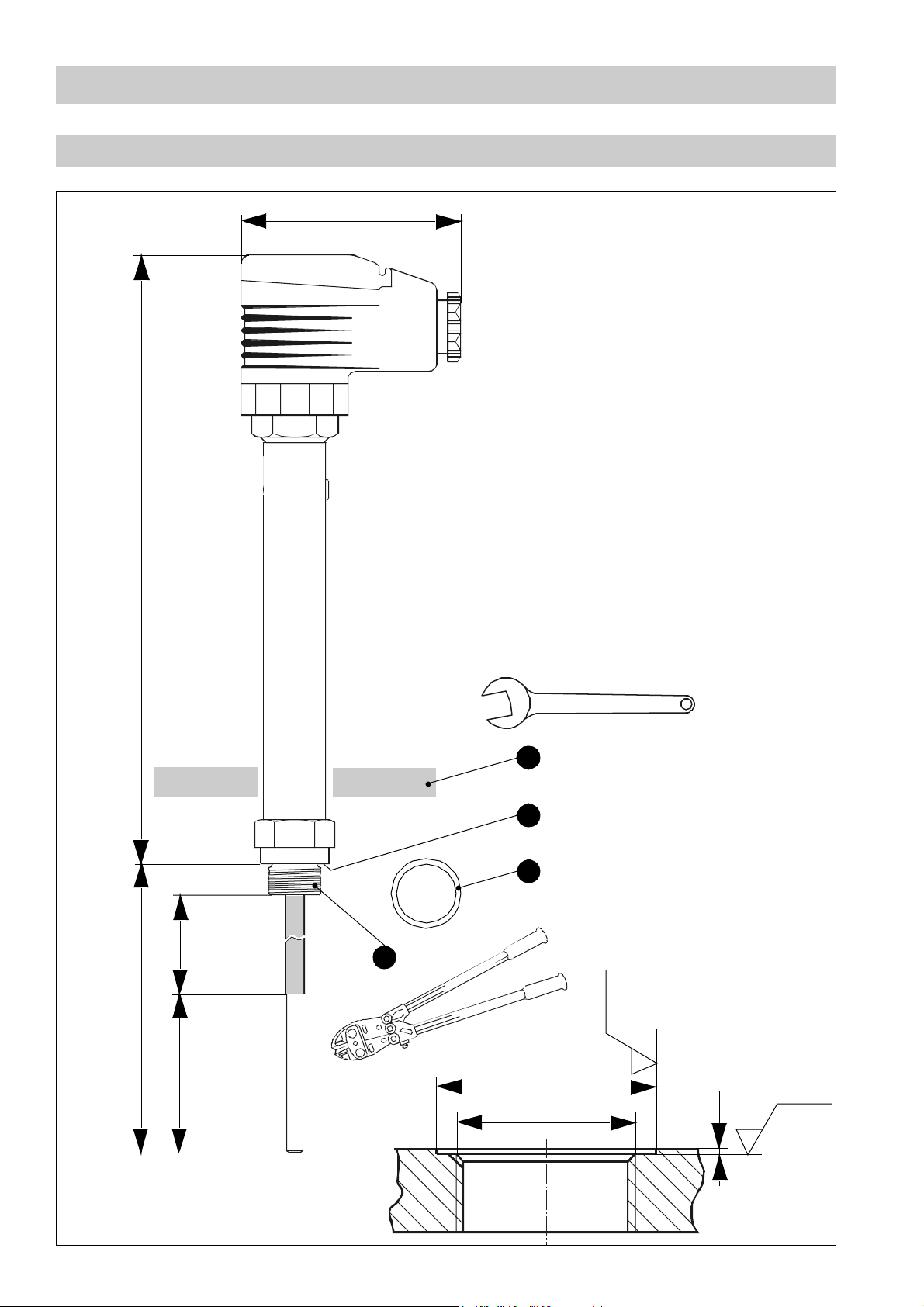
Dimensions
– continued –
70
190Length supplied
A. F. 22
A
B
C
30
D
50
Fig.1 Fig.2
8
Ø 23
Screwed 3/ 8" BSP,
Ra12.5
0.5
Ra3.2
Page 9

Functional Elements
NRG 16-4
MAX 70 °C
E
F
G
H
J
%
MAX 95 %
IP 65
K
L
I
Fig. 3
Key
A
Thermal insulation
Seating surface
B
C
Joint ring 17x 21 form D to DIN 7603 , made from 1.4301, bright annealed
D
Electrode screwed to 3/8" BSP, ISO 228-1
E
Screw M4
F
Cover
G
Upper part of the terminal box
H
Connecting plate
I
Insulating plate
J
Contact plate of level electrode
K
Cable strain relief
L
Cable gland M16 (PG 11)
9
Page 10

Installation
Cutting electrode tip to length
1. Carefully determine the required length of the electrode tip in accordance with the level-dependent
switchpoint (the length should be measured from the gasket face of the screwed connection). In
steam boilers operating at full load arching of the water level may occur. This phenomenon should be
taken into account when determining the length of the electrode tip.
2. Cut the electrode tip to length using a bolt cutter or a metal cutting saw.
3. Deburr the face of electrode tip end.
4. Strip off 50 mm of PTFE insulation from the end of the electrode tip (see Fig. 1). Make sure that the remaining insulation is at least 30 mm long, measured from the lower edge of the screwed connection.
Mounting electrode
In steam or (pressurised) hot water boilers the level electrode can be installed vertically or with an inclination of 45°.
1. Check seating surfaces of threads or mounting flange provided on vessel or boiler standpipe (see Fig.1
and Fig.2). If necessary rework the surfaces according to the specifications indicated in the drawing.
B
2. Place supplied joint ring onto the seating surface of the level electrode.
C
B
3. Apply a light smear of silicone grease to the electrode thread.
4. Screw electrode into threads or flange provided on vessel (see Fig.2) and tighten with a 22 mm openend spanner. The torque required when cold is 63 Nm.
Attention
■
The seating surfaces and threads on the vessel and mounting flange must be accurately
machined.
■
Do not bend the electrode tip when cutting.
■
Do not subject electrode to physical shocks.
■
Use only the supplied ring joint 17 x21 form D to DIN 7603, made from 1.4301, bright annealed!
■
Do not insulate the threads with hemp or PTFE tape!
■
Do not lag the electrode body above the hexagonal part.
■
Make sure that there is an air gap of > 14mm around the electrode rod. Note that the air
distance between the electrode rod and earth (flange, vessel wall) must not be less than 14mm.
10
■
Be sure that the electrode insulation is at least 30mm long.
■
The specified torques must be strictly observed.
Page 11

Installation
– continued –
Mounting electrode
– continued –
Note
Observe TÜV (German Technical Supervisory Association) regulations when using the level
electrode in steam boilers or (pressurised) hot water plants.
■
For the approval of the boiler standpipe the relevant local and national regulations must
be observed.
■
Several examples of installation are given on page 12.
■
The angle of installation of the electrode must not exceed 45° and the length of the electrode rod is limited to 500mm!
■
If installed outdoors the level electrode
tection cover.
Tools
■
Open-end spanner 22mm A. F.
must
be equipped with a GESTRA weather pro-
■
Bolt cutter or metal cutting saw
■
Flat file, medium cut
11
Page 12

Examples of Installation
3/8"BSP3/8"BSP
Fig.4
1
2
DN50
20
1
2
DN50
3
4
Ø20
<1500
4
4
5
20
3
Ø20
5
8
6
8
9
Ø20
<90°
>10
10
Fig. 5
Ø20
>10
<90°
3/8"BSP
6
9
10
3
3/8"BSP
Ø20
20
Ø20
DN100
24.5
<90°
1
3/4"BSP
1
DN20
4
>88.9
24.5
2
5
7
<1500
12
8
5
4
9
>10
>10 >20
9
11
DN20
12
Fig.6
Fig. 7
DN20
Page 13

Key
1
Flange PN40, DN50 to DIN 2501-1
Flange PN40, DN100 to DIN 2501-1
2
For the approval of the boiler standpipe with connecting flange the relevant
regulations must be considered
3
Provide vent hole as close to the boiler wall as possible!
4
High water (HW)
5
Electrode rod d = 5mm
6
Protection tube >DN 80
7
Protection tube >DN 100
8
Electrode distance > 14mm
9
Low water NW
10
Reducer DIN 2616-2, K88.9x 3.2-42.4x2.6 W
Reducer DIN 2616-2, K114.3x 3.6-48.3x2.9 W
11
12
Centre distance of connecting flanges
13
Page 14

Wiring
Terminal box
Use screened cable type I–Y (St) Y 2x 2x0.8mm ² or LIYCY 4 x0.5mm² for wiring.
1. Unscrew screw . Fig.3
2. Remove terminal box from level electrode, leaving the insulating rubber plate on the contact
J
plate .
3. Remove cover .
4. Press connecting plate out of the upper part of the terminal box .
E
I
F
H G
The electrode terminal can be turned in steps of 90°.
5. Detach cable gland and cable strain relief from the upper part of the terminal box .
6. Run cable through cable gland and upper part of the terminal box and wire the terminal of the
connecting plate according to the wiring diagram (see Fig. 8).
7. Press connecting plate into the upper part of the terminal box and align the cable.
8. Fix cable with cable strain relief and cable gland firmly into position.
9. Replace cover and insert screw .
10.Put upper part of the terminal box onto the level electrode and fix it with screw .
L K G
L G
H
H G
K L
F E
E
If several level electrodes are to be installed in one steam boiler or vessel we recommend labelling the
terminal box with the electrode type.
14
Page 15

Wiring
Wiring diagram
– continued –
1
2
3
3
Fig. 8
Key
1
Level switch NRS...
2
For wiring of level switch see installation instructions NRS ...
3
Electrode tip
Tools
■
Screwdriver for slotted screws, size 2.5, completely insulated according to DIN VDE 0680-1
■
Crimping pliers for end sleeves
■
Wire stripper
Commissioning
Check wiring
Check that the level electrode NRG 16-4 and the associated level switch are connected in accordance with
the wiring diagram (see Fig. 8).
Apply mains voltage
Apply mains voltage to the level switch.
15
Page 16

Malfunctions
Fault finding list for troubleshooting
Level electrode immersed - no function
Fault: Mains voltage is not applied to the level switch.
Remedy: Switch on mains voltage. Connect electrode according to wiring diagram.
Fault: The electrode body does not have earth connection to the boiler.
Remedy: Clean seating surfaces and screw in the equipment together with the supplied joint ring
17x21, form D to DIN 7603 (made from 1.4301), bright annealed. Do not insulate level electrode with hemp or PTFE tape!
Level electrode exposed - no function
Fault: The internal insulation of the electrode rod is damaged.
Remedy: Replace level electrode.
Fault: The electrode tip has earth contact.
Remedy: Check and, if necessary, change position of installation.
Fault: The vent hole in the protection tube does not exist, is obstructed or flooded.
Remedy: Check protection tube and, if necessary, provide vent hole.
For more information see the Installation Instructions of the level switch.
If faults occur that are not listed above or cannot be corrected, please contact our service centre or
authorized agency in your country.
16
Page 17

Decommissioning
Danger note
Danger
Risk of severe burns and scalds to the whole body! Before installing the level electrode make
sure that the vessel or the external pot are depressurised (0 bar) and cooled down to room
temperature (20°C).
Disposal
Dismantle the level electrode and separate the waste materials, using the specifications in the table "Materials" as a reference. Electronic component parts such as the circuit board must be disposed of separately!
For the disposal of the level electrode observe the pertinent legal regulations concerning waste disposal.
17
Page 18

www.gestra.de
España
GESTRA ESPAÑOLA S.A.
Luis Cabrera, 86-88
E-28002 Madrid
Tel. 00 34 91 / 51 52 032
Fax 00 34 91 / 41 36 747; 51 52 036
E-mail: aromero@flowserve.com
Great Britain
Flowserve Flow Control (UK) Ltd.
Burrel Road, Haywards Heath
West Sussex RH 16 1TL
Tel. 00 44 14 44 / 31 44 00
Fax 00 44 14 44 / 31 45 57
E-mail: gestraukinfo@flowserve.com
Italia
Flowserve S.p.A.
Flow Control Division
Via Prealpi, 30
I-20032 Cormano (MI)
Tel. 00 39 02 / 66 32 51
Fax 00 39 02 / 66 32 55 60
E-mail: infoitaly@flowserve.com
Poland
GESTRA POLONIA Spolka z.o.o.
UI. Schuberta 104
PL - 80-172 Gdansk
Tel. 00 48 58 /306 10-02 od 10
Fax 00 48 58 /306 33 00
E-mail: gestra@gestra.pl
Portugal
Flowserve Portuguesa, Lda.
Av. Dr. Antunes Guimarães, 1159
Porto 4100-082
Tel. 0 03 51 22 / 6 19 87 70
Fax 0 03 51 22 / 6 10 75 75
E-mail: jtavares@flowserve.com
USA
Flowserve DALCO Steam Products
2601 Grassland Drive
Louisville, KY 40299
Tel. 00 15 02 / 4 95 01 54, 4 95 17 88
Fax 00 15 02 / 4 95 16 08
E-mail: dgoodwin@flowserve.com
GESTRA AG
Postfach 10 54 60, D- 28054 Bremen
Münchener Str. 77, D -28215 Bremen
Telefon +49 (0) 421 35 03-0
Telefax +49 (0) 421 35 03-393
E-Mail gestra.ag@flowserve.com
Internet www.gestra.de
818596-00/905agt ©2005 GESTRA AG Bremen Printed in Germany
 Loading...