

Page 1

GESTRA Steam Systems
NRGS 15-1
Installation Instructions 818479-00
Level Switch NRGS 15-1
Page 2

Contents
Page
Important notes
Usa ge for the intended purpose.......................................................................................8
Safety note.......................................................................................................................8
Danger .............................................. ...............................................................................8
Explan atory Notes
Scope of supply ...............................................................................................................9
Function............................................ ...............................................................................9
Technical data................................................................................................................10
Corrosion resistance......................................................................................................12
Establishing Functions
Select functio n ...............................................................................................................13
Factory setting ...............................................................................................................14
Cutting electrode ti ps to length ......................................................................................14
Adjust functio n ...............................................................................................................15
Set sensitivity range.......................................................................................................15
Tools ........................................................... ...................................................................15
Installation
Level switch NRGS 15-1................................................................................................16
Align terminal box ..........................................................................................................17
Remove terminal box.....................................................................................................17
Mount terminal box .......................................................... ..............................................18
Tools ........................................................... ...................................................................18
Wiring
Connec t level switch NRGS 15-1...................................................................................19
Tools ........................................................... ...................................................................19
Wir ing diagram............................................ ...................................................................20
Commissioning
Chec k wiring ..................................................................................................................21
Apply mains voltage.......................................................................................................21
Chec k switching functions..............................................................................................22
Malfunctions / Troubleshooting
Fault finding list..............................................................................................................24
Replace electronic circuit board.....................................................................................25
2
Page 3

Conte nts
Page
Annex
Adjust other functions ....................................................................................................26
Installation in non-metallic vessel ..................................................................................27
Revise d..........................................................................................................................27
Examples of Installation.................................................................................................28
3
Page 4
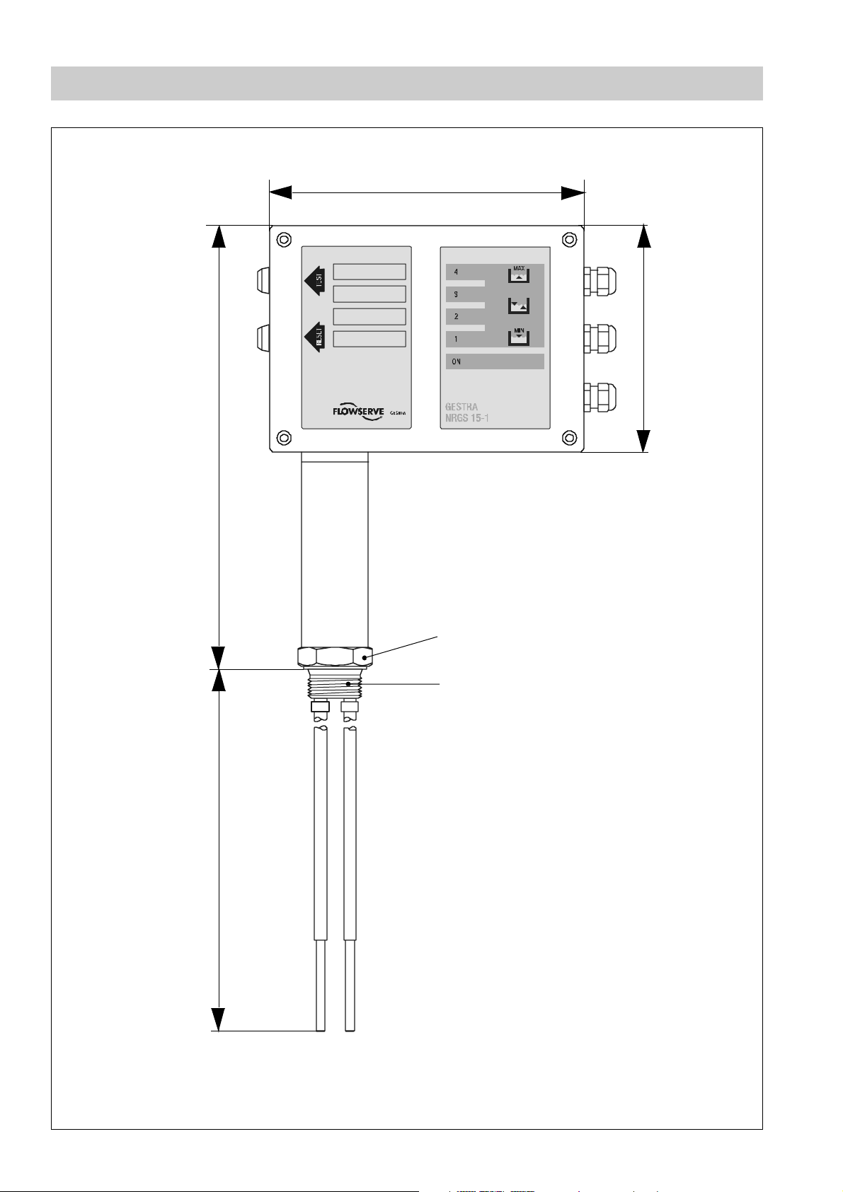
Dimensions
180
130
~355 1000
b = 60
12
A. F. 41
1" BSP to DIN ISO 228
Fig. 1
4
Page 5
Func tio na l El eme nts
A
B
40
C
D
1
234
A. F. 41
E
>14
Fig. 2
50
65-70
Fig. 3
Ø 40
1" BSP to DIN
N10
0.5
N8
5
Page 6
Functional Elements
Fig. 4
MAX 70 °C
%
MAX 95 %
IP 65
F
G
8
O
9
N
M
2
7
6
1
4
3
3 4
5
H
15
14
13
12
11
10
9
8
7
7
7
6
6
6
5
5
5
4
4
4
I
2
1
2
1
J
JKL
Fig. 5
6
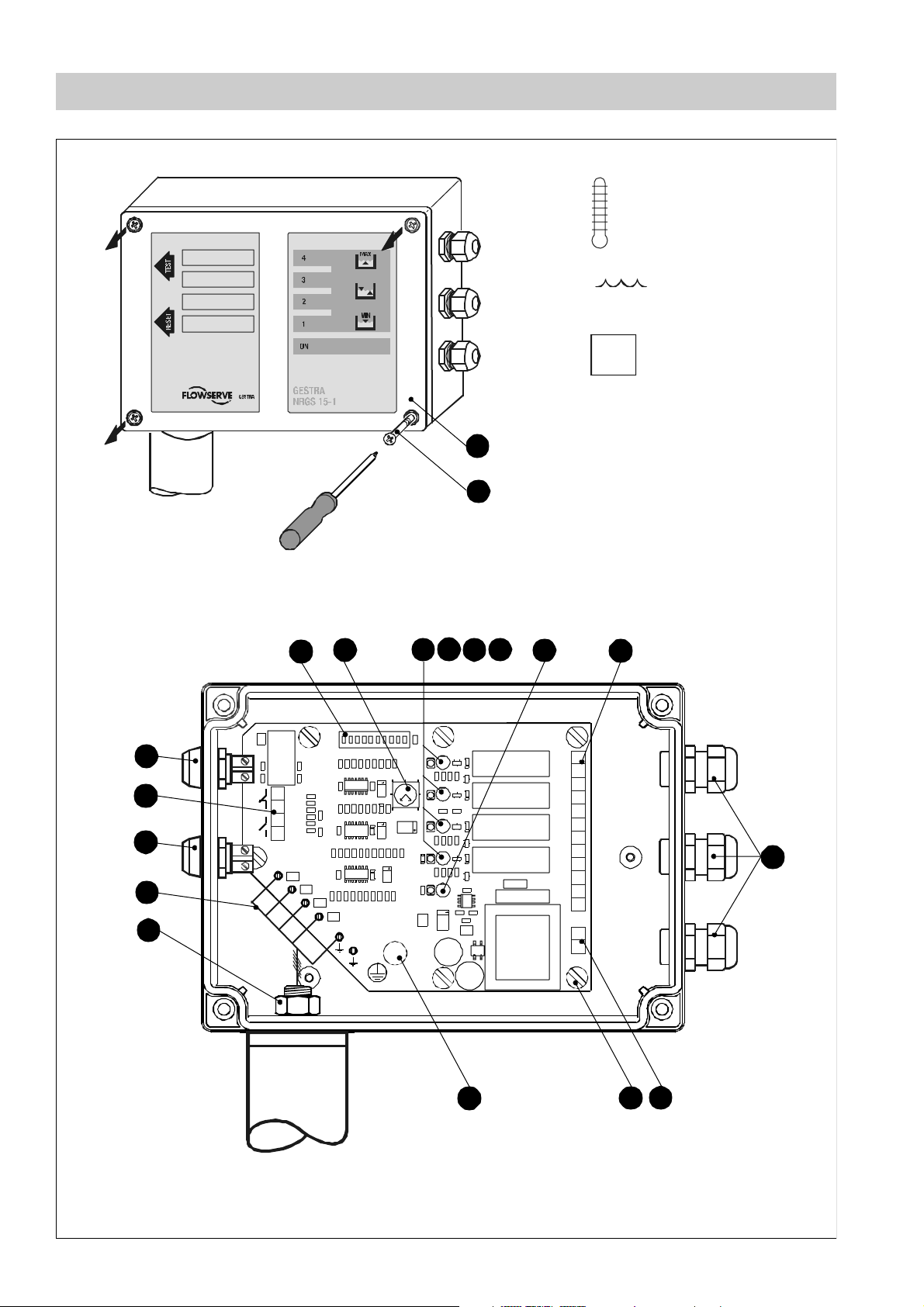
Page 7

Key
1
LED 1 red
2
LED 2 red
3
LED 3 yellow
4
LED 4 red
5
LED "Mains supply ON" green
6
Code switch S1
7
Potentiometer for ti me delay (0 to 30 sec.)
8
TEST button
9
RESET button
A
Gasket
Therma l insulation
B
C
Electrode thread 1" BSP to DIN E N 228
Joint ring Ø33x39 to DIN 7603 made from 1.4301
D
E
Seating surface
F
Housing lid
G
Housing screws (cross recess head screws M4)
H
Terminal strip for control cable connection
Cable gland 3xM16x1.5
I
J
Terminal strip for mains supply
K
Fixing screws for electronics insert
L
PE connection
M
Fixing nut for terminal box
N
Term inal lugs for electrode wires, functional earth
O
Term inal strip for pushbuttons
7
Page 8
Important notes
Usage for the intended purpose
The level switch NRGS 15 - 1 is designed for detecting and signalling levels in liquids with
a mi nimum electrical conductivity.
The equipment must only be used within the admissible pressure and temperature ratings.
Any type of use differing from the usage described above must be considered as improper. The resulting risk will have to be borne by the user alone. The manufacturer hereby
expres sly rejects a ny claims for any damage resulting from improper usage.
Safety note
The equipment must only be installed and c ommissioned by qualified and competent
staff.
Retrofitting and maintenance work must only be performed by qualified staff who through adequate training - have achieved a recognised level of competence.
Danger
Danger
When loosening the level electrode steam or hot water might escape. This
presents the danger of severe s calds to the whole body.
It is essential not to mount or dismantle the electrode unless the boiler
pressure is verified to be zero!
The electrode becomes hot during operation. Touching the hot equipment
presents the risk of severe burns to hands and arms. All installation, removal
and maintenance work must only be performed when the system is cold.
Danger
The term inal strip of the level sw itch is live during operation. This presents
the danger of electric s hock!
Cut of f po we r s upp l y before opening the housing cover of the level switch!
After removing the housing cov e r check aga in that the system is deenergized.
To check the power supply or the correct functioning, switch the level switch
on again . This work must only be performed by qualified personnel.
8
Page 9

Explanatory Notes
Scope of supply
NRGS 15-1
■ 1 Level electrode with four tips
■ 1 Terminal box with integrated level switch
■ 1 Joint ring Ø33x39 to DIN 7603, made of 1. 4301 E8P
■ 1 Installation manual
or
NRGS 15-1
■ 1 Level electrode with four tips
■ 1 Terminal box with integrated level switch and built-in Test and Reset pushbutton
■ 1 Joint ring Ø33x39 to DIN 7603, made of 1. 4301 E8P
■ 1 Installation manual
Function
The level switch NRGS 15-1 is a compact-type system consisting of a level electrode
with four tips and an integrated level switch. For the correct functioning of the equipment
the water must have a minimum conductivity of >0.5µS/cm at 25°C.
In the inte grated level switch a time- delayed switching channel, an output relay and a
signal LED are assigned to each one of the four electrode tips.
The functions of the sw itching channels 1 and 4 are fixed, the switchting chan nels 2 and
3 can be adjusted via code switch to suit individual requirements. The tips of the electrode
are cut to l ength on site in order to establish the desired switchpoints of the associated
switching channels.
The following functions are possibl e:
■ Electrode rod 1 exposed / switching channel 1 energizes relay 1 = low level 1 with
optional performance test and lock-out function
■ Electrode rod 2 exposed / switching channel 2 energizes relay 2 = low level 2
■ Electrode rod 3 exposed or submerged / switching channel 3 energizes relay 3 as a
function of time = timed pump control (fill/discharge control)
■ Electrode rod 3 exposed or submerged / switching channel 3 energizes relay 3
= on/off pump control (fill/discharge control)
■ Electrode rod 4 submerged / switching channel 4 energizes relay 4 = high level
9
Page 10

Expl an ato ry No tes – continued –
Technical data
Service pressure
25 barg at 224 °C
Connection
Screwed 1" BSP, DIN ISO 228
Materials
Screw-in housing: 1.4571, CrNiMoTi 17 12 2
Electrode rods: 1.4571, CrNiMoTi 17 1 2 2
Electrode insulati on: PTFE
Spacer disc: PTFE
Terminal box: polycarbonate
Electrode rods
Length supplied : 1000 mm
Diameter: 5 mm
Mains supply
220–240V +10/-15%, 50/60 Hz
110–120V +10/-15%, 50/60 Hz
24 V +10 /-15%, 50/60 Hz (opti onal)
Power consumption
3VA
Se nsitivity (at 25 °C)
Range 1: 0.5 µS/cm
Range 2: 10 µS/c m
The selection of the above range is done via a code switch.
Electrode voltage
20 Vss
Output
Four volt-free rel ay contacts.
Max. contact rating with a s witching voltage of 24 V A C/DC, 115 V AC and 230 V AC:
resistive / inductive 4 A.
Ensure interference suppression by providing contactor with an arc suppressor RC combina tion.
Contact material AgNi 0.15.
Energizing/de-energizing delay
Relay 1 and 2: 1 sec., factory set
Relay 3: 0-30 sec., adjustable via potentiometer
Relay 4: 3 sec., factory set
10
Page 11

Expl an ato ry No tes – conti nued –
Technical data - continued -
Indicators and adjustors
3 red LEDs to indicate "Low leve l alarm 1 + 2 / Hi gh level".
1 yellow LED to indica te "Pump ON".
1 green LED to indicate "Mains supply ON".
1 ten-pole c ode switch to select the sensitivity r ange and to establish the functions.
1 test but ton in the terminal box to c heck the function of switching channel 1
(connec ted to terminals).
1 reset button in the terminal box to reset the lock-out function (connec ted to terminals).
Cable entry / Wiring
3 cable glands with in tegral cable clamps (M 16).
1 two-pole terminal str ip for power supply.
1 twelve-pole terminal strip for connecting the control cables.
1 four-pole terminal strip for test and reset button.
Screw-type terminal strips, conductor size <1.5 mm2.
Protection
IP 65 to DIN EN 60529
Max. admissible ambient temperature
70 °C
Weight
NRGS 15-1: approx. 1.4 kg
11
Page 12

Expl an ato ry No tes – continued –
Technical data - continue d -
Name Plate 110-120 and 220-240 VAC
Vor Öffnen des Deckels. Gerät
freischal ten! Betriebsanl eitung
beachten
Before removing cover isolate from
power supplies . See install ation
instructions
Avant d'ouvrir le couverc le
dèconnecter complètement l'apparei l.
Voir instructions de montage.
PN 25 G 1 1.4571
PmaxPmax
Tmax Tmax
Tamb ( )133°F 70°C
362psi 25 bar ()
435°F (224°C)
IP 65
110 - 120 VAC 50 / 60 Hz
0 - 30s
3VA
0, 5 / 10 µS /cm
Vor Öffnen des Deckels. Gerät
freischal ten! Betriebsanl eitung
beachten
Before removing cover isolate from
power supplies . See install ation
instructions
Avant d'ouvrir le couverc le
dèconnecter complètement l'apparei l.
Voir instructions de montage.
PN 25 G 1 1.4571
PmaxPmax
Tmax Tmax
Tamb ( )133°F 70°C
362psi 25 bar ()
435°F (224°C)
IP 65
220 - 240 VAC 50 / 60 Hz
0 - 30s
3VA
0, 5 / 10 µS /cm
GESTRA GmbH
Münchener Straße 77
D-28215 Bremen
Phone: +49 (0) 421 / 3503-0
gestra.gmbh@flowserve.com
GESTRA GmbH
Münchener Straße 77
D-28215 Bremen
Phone: +49 (0) 421 / 3503-0
gestra.gmbh@flowserve.com
Co rro s ion re si stan ce
If the NRGS 15-1 is used fo r its intended purpose, its safety is not impaired by corrosion.
12
Page 13

Establ ishi ng Func tio ns
Select function
Before installing and commissionin g the NRGS 15-1 ascertain the settings for the
required functions.
Five functions are available:
ON
Function 1
Electrode rod 1 Low level 1 / bu rner off
Electrode rod 2 Low level 2
Electrode rod 3 Timed pump control (fill control) tv=0 – 30 sec.
Electrode rod 4 High level
Function 2
1
2354 678910
ON
1
23 54 678910
Electrode rod 1 Low level 1 / bu rner off with test an d reset button
Electrode rod 2 Low level 2
Electrode rod 3 Timed pump control (fill control) tv=0 – 30 sec.
Electrode rod 4 High level
Function 3
Electrode rod 1 Low level alarm 1 / burner off
Electrode rod 2 Feed pump on (fill control)
Electrode rod 3 Feed pump off (tv=0 sec.)
Electrode rod 4 High level
Function 4
Electrode rod 1 Low level alarm 1 / burner off with test and reset button
ON
123 54 678910
ON
123 54 678910
Electrode rod 2 Feed pump on (fill control)
Electrode rod 3 Feed pump off (tv=0 sec.)
Electrode rod 4 High level
13
Page 14

Establishing Functions – cont inued –
Select function - continu ed -
ON
Function 5
Electrode rod 1 Low level alarm 1
Elec t r od e ro d 2 Pum p of f
Elec t r od e ro d 3 Pum p on (d i sch arg e co nt ro l ) tv=0 sec .
Electrode rod 4 High level
Fa ctory se ttin g
The factory setting of level switch NRGS 15-1 without pushbuttons is function 1 and with
pushbuttons is function 2.
123 54678910
The preset time delay for pump control is 5 sec. and the preset sensi tivity range is
10 µS/cm.
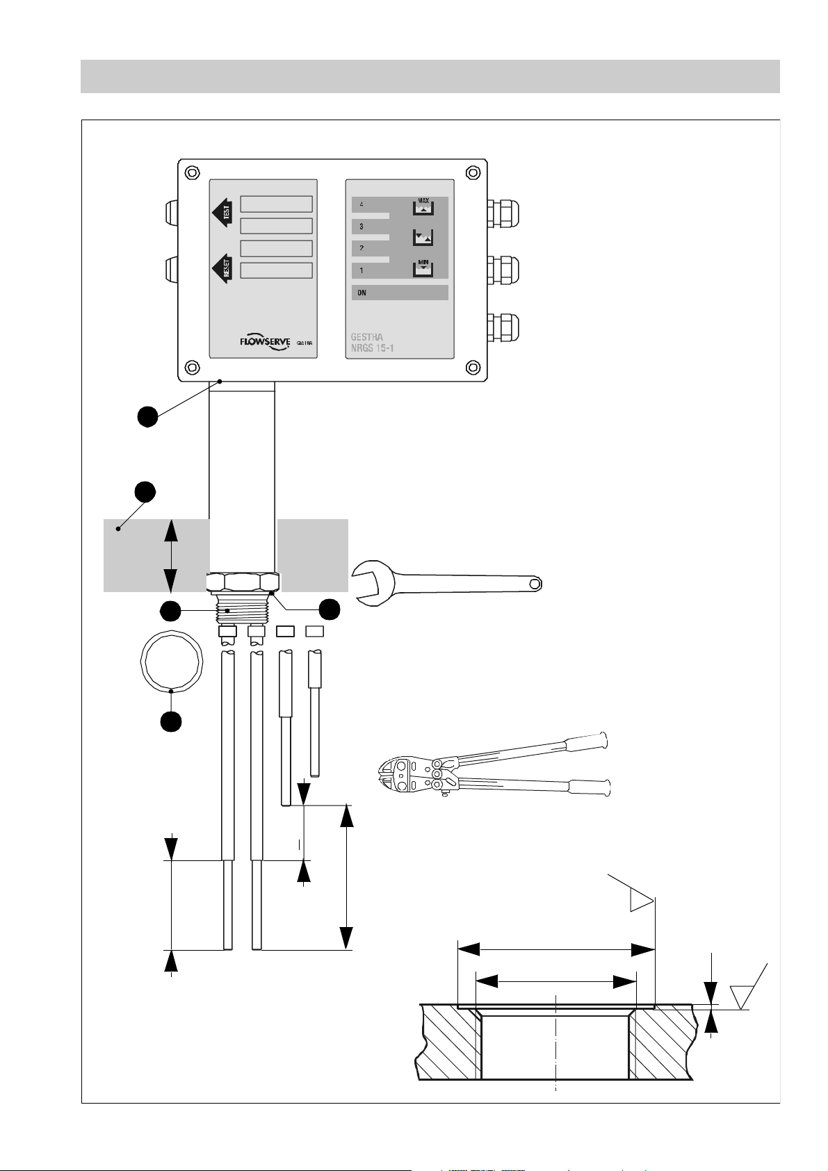
Cutting electrode tips to length
1. Determine the lengths of the electrode rods as a function of the level-dependent
switchpoints (measured from the gasket face ) and enter the data in the table blow.
E
2. Then cut all electrode tips (see Fig. 2) to the required lengths by using a bolt cutter.
3. Deburr faces of electrode tip ends.
4. Strip off 50mm of PTFE ins ulation from the ends of the electrode tips (see Fig. 2).
Make sure that there is an electrical resistance path of >14mm between the electrode tips.
5. Arrange PTFE spacer discs so that the electrode tips cannot com e into contact with
each other.
Electrode
Function
tip
Ca ble /
Connector
Length
[mm]
1 1
2 2
3 3
4 4
14
Page 15

Establishing Functions – continu ed –
Adjust function
1. Undo the housing screws and remove the housing lid.
2. Set the code switch to the desired function (see “Select function“). To set the code
switch located on the electronics insert (see Fig. 5) use a screwdriver with a thin
6
6
G F
blade.
3. Use a waterproof marker to enter the established functions in the labelling boxes on
the lid (see Fig. 4).
4. After adjusting the functions replace housing lid and fasten the housing screws .
F G
Set sensitivity range
The sensitivity is set at our works to > 10µS/c m.
If the electrical conductivity of the boiler water is below 10µS/cm at 25°C you have to
change the sensitivity range.
1. Undo the housing screws and remove the housing lid .
2. Set the code switch such that the desired function is established. To set the c ode
switch located on the electronics insert (see Fig. 5) use a screwdriver with a thin
6
6
G F
blade.
The following functions can be adjus ted via code switch:
Code switch S1 Setting
ON
123 54 678910
Sensitivity >
ON
Sensitivity >
123 54 678910
3. After adjusting the functions replace housing lid and fasten the housing screws .
0.5µS/c m at 25 °C
10µS/cm at 25°C
F G
Tools
■ Bolt cutter
■ Hacksaw
■ Flat file, medium cut
■ Screwdriver for cross head screws, s ize 2
■ Screwdriver for slotted screws, siz e 2.5, completely insulated according to VDE 0680
15
Page 16

Installation
Le ve l s wit c h N RG S 15-1
We highly recommend that only qualified staff should carry out installation work in accordance with these installation instructions. The manufacturer expressly rejects any claims
for damage caused by improper installation.
Before installing the electrode cut the electrode rods to length, make sure that 50mm of
the PTFE insulation are stripped off (see Fig. 2) and establish the functions.
The supplied spacer discs must be slipped ov er the electrode tips and distributed uniformly to ensure sufficient spacing between the tips.
1. Check that seating surfaces of threads or mounting flange provided on vessel or boiler standpipe (see Fig. 3) are accurately machined. If necessary rework the surfaces
according to the specifications indicated in the drawing.
2. Place joint ring (supplied with the electrode) onto the seating surface of the elec-
D E
trode.
3. Apply a light smear of silicone grease to the electrode thread.
4. Screw electrode into threads or flange provided on v e sssel (see Fig. 3) and tighten
with a 41 mm open-end spanner. The torque required when cold is 160 Nm.
5. Provide a max. thermal insulation of boiler of 40mm at electrode (see Fig. 2).
Attention
Do not s ubject the electrode tips to shocks and do not bend the electrode
tips when mounting.
Use only joint ring Ø33x39 DIN 7603 made from 1.4301 E8P. Do not in-
D
sulate the threads with hemp or PTFE tape!
Do not lag the electrode body above the hexgonal part.
The electrode must only be installed i n a vertical position.
The specified torques must be strictly observed.
16
Note
For the approval of the boiler standpipe (see Fig. 3) the relevant regulations
must be considered.
Carry out the installation work in co mpliance with the installation examples
given in this installation manual.
Page 17

Installation – c ontinued –
Align terminal box
Align the terminal box s uch that the LEDs , , , , can be seen by the oper ator.
1. Undo the housing screws and remove the housing lid .
G
2. Use open-end spanner A. F. 18 (19)mm to loosen the fixing nut and turn the ter -
1 2 3 4 5
F
M
minal box into the desi red direction (cable gland).
3. Re-tighten the fixing nut with a torque of 25 Nm.
4. Replace the housing lid and tighten the housing screws firmly .
M
F
G
If necessary you can take off the terminal box in order to align the electrode part. The terminal box must be re-installed after alignment.
Rem ove t erm i nal b ox
1. Undo the housing screws and remove the housing lid .
2. Unplug the electrode wires from terminal lugs for electrode wires, functional earth
G F
N
and mark them.
3. Use open-end spanner A. F. 18 (19)mm to unscrew the fixing nut . Pull electrode
wires through fixing nut .
M
M
4. Remove terminal box. R un all electrode wires through the hole for the fixing s crew
(see Fig. 5).
5. Remove the gasket between the electrode part and the housing.
A
17
Page 18

Installation – cont inued –
Mount terminal box
1. Put gasket onto electrode part.
A
2. Run all electrode wires through the hole for the fixing screw (see Fig. 5) in the
terminal box.
3. Place the terminal box onto the electrode part and turn it into the desired direction
(cable gland). Make sure that the gasket is properly placed between the electrode
part and the housing.
4. Pull al l electrode wires through fixing nut . Use an open-end spanner A. F. 18
M
(19)mm to fasten the hexagon nut to the fixing screw, applying a torque of 25 Nm.
5. Connect the electrode wires according to the wiring diagram (see Fig. 6) to the terminal lugs for electrode wires, functional earth .
6. Replace the housing lid and tighten the housing screws .
F G
N
Attention
Close the lid of the housing whenever interrupting the installation or re-
F
moval work of the terminal box.
Check the gasket for signs of damage. Re-use only undamaged gas-
A
kets.
Tools
■ Open-e nd spanner 41 mm A. F.
■ Open-end spanner 18 (19) mm A. F.
■ Screwdriver for cross-recess head screws, size 2.5, completely insulated according to
VDE 0680
18
Page 19

Wir ing
Connect level switch NRGS 1 5-1
Use multi-core flexible control cable with a min. conductor size of 0.75 mm² as mains and
control cables.
1. Undo the housing screws and remove the housing lid .
2. Unplug the two-pole terminal strip and the twelve-pole terminal strip from the
G F
J H
electron ics insert.
3. Strip off approx. 40 mm of cable insulation coating and remove approx. 5 mm of conductor end insulation.
4. Loosen cable glands and run the mains cables through the lower cable gland
and the control cables through the upper cable glands .
I I
I
5. Connect mains and control cables according to the wiring diagram (inside of housing
lid) to te rmi nal strips , .
6. Plug terminal strips , to electronics insert.
7. Seal cable entries by tightenting cable glands . Use sealing plugs for cable
H J
H J
I I
glands that are not used.
8. Replace the housing lid and tighten the housing screws firmly .
F G
Attention
The following relocations of cables with basic insulation are not permissible: Mains and control cables in low voltage areas
Provide level switch and control circuit with a slow-blow 2.5A fuse.
Provide connected contactors with RC combinations according to manu-
facturer's specification to ensure interference suppression.
Note that the sealing plugs are not scope of the supply.
Tools
■ Screwdriver for cross recess head screws, size 1 and 2
■ Screwdriver for slotted screws, siz e 2.5, completely insulated according to VDE 0680
19
Page 20

Wi r i ng – conti nued –
Wiring diagram
15
Electrode
cables
TEST
RESET
4
3
2
1
4
1
2
3
4
3
2
1
14
13
12
11
10
9
8
7
6
5
4
Mains supply
Fig. 6
PE connection
20
Page 21

Commissioning
Check wiring
1. Make sure that the level switch is correctly wired in accordance with the wiring
diagram (see Fig. 6).
2. Make sure that the mains voltage agrees with the specification on the name plate.
Apply m a in s vo lt age
1. Undo the housing screws and remove the housing lid .
2. Apply mains voltage. The green LED is illuminated. The other LEDs are lit as a
G F
5
function of the water level.
3. Check that al l functions of the respective switchpoints work correctly. The
LEDs , , , s erve as optical indicat ors of the asso ciated switchpoints.
1 2 3 4
(see “Check switching functions“).
4. After establishing the functions replace housing lid and tighten the housing
screws .
G
F
Danger
The term inal strip of the level sw itch is live during operation. This presents
the danger of electric s hock!
Cut of f po we r s upp l y before opening the housing cover of the level switch!
After removing the housing cov e r check aga in that the system is
de-energized.
To check the power supply or the correct functioning, switch the level switch
on again . This work must only be performed by qualified personnel.
21
Page 22

Commissioning – contin ued –
Check switching functions
Use the following table as reference when checking the individual switching functions.
Electrode rod1 = low level 1
Electrode rod1 emerges Relay1 is de-energized after 1sec.
Elec t r od e ro d1 ente rs th e
liquid
Press TEST button Relay1 is de-energized and locked out after 1sec.
Press RESET button for 3s Relay1 is energized after 1sec. LED1 off
Electrode rod1 emerges Relay1 is de-energized and locked out after 1sec.
Elec t r od e ro d1 ente rs th e
liquid
Press RESET button for
3sec.
Relay1 is energized after 1sec. LED1 off
Te st an d lock- ou t fu nc tio n
Relay1 is energized after 1sec. LED1 off
Electrode rod2 = low level 2
LED1
illuminated
LED1
illuminated
LED1
illuminated
Electrode rod2 emerges Relay2 is de-energized after 1sec.
Elec t r od e ro d2 ente rs th e
liquid
Elec t r od e ro d4 ente rs th e
liquid
Electrode rod4 emerges Relay4 is de-energized after 3sec. LED4 off
Relay2 is energized after 1sec. LED2 off
Electrode rod4 = high level
Relay4 is de-energized after 3sec.
LED2
illuminated
LED4
illuminated
22
Page 23

Commissioning – contin ued –
Check switching functions - continued -
Electrode rod3 = timed pump control (fill control)
Electrode rod3 em erges Relay3 is energized, p ump ON
Electrode rod3 enters the
liquid
Relay 3 is de-energized too early or too late: Increase or decrease time delay with the aid of the
potentio meter and let el ectrode ti p3 emerge or enter the liquid again. Repeat the process until
you have found the correct switchpoint for the pump. If 30sec. time delay is not enough for filling
the boiler, please select the operation mode "on-off pump control".
Electrode rod3 = on-off pump control (fill control)
Electrode rods2 and 3
exposed
Electrode rod2 enters the
liquid
Electrode rod3 enters the
liquid
Relay3 is de-energized after a preset time delay
(0–30 sec.) = pump OFF
Set potentiometer for time delay to 0 sec.
Relay3 is energized, pump ON
Relay3 is de-energized = pump OFF LED3 off
LED3
illuminated
LED3 of f
LE Ds2 and 3
illuminated
LED2 of f
Electrode rods2 and 3 = on-off pump control (discharge control)
Set potentiometer for time delay to 0 sec.
Electrode rods2 and 3
submerged
Electrode rod3 emerges LED3 off
Electrode rod2 emerges Relay3 is de-energized = pump OFF
Relay3 is energized, pump ON
LED2 of f and
LED3
illuminated
LED2
illuminated
23
Page 24

Ma lfu nct ions / Trou bl esho ot ing
Fault finding list
Switchpoint "Pump OFF" exceeded - no function
Fault: Mains voltage is not applied.
Remedy:Switch on mains voltage. Connect l evel switch according to wiring diagram
(Fig. 5).
Fault: The electrical conductivity is too low.
Remedy:Set code switch to 0.5 µS/cm.
Fault: The earth connection to the v essel is interrupted.
Remedy:Clean seating surfaces (see Fig. 3) and inser t metal joint ring Ø33x39
DIN 7603 (made from s. s. 1.4301). Do not insulate the level switch with
hemp or PTFE tape!
6
D
Fault: Electronic circuit board defective.
Remedy:Replace electronic circuit board.
Level below switchpoint "Low level" - no function
Fault: The electrode tips have earth contact.
Remedy:Check and, if necessary, change position of installation.
Fault: If the equipment is installed inside the boiler: The vent hole in the protection
tube does not exist or is obstructed.
Remedy:Check installation of level switch. Make sure that the level in the protection
tube corresponds to the actual water level (see Exa mples of Installation).
Switchpoint has been reached - incorrect function
Fault: The switching function has not been assigned correctly. The electrode tips
have been cut to the wrong length.
Remedy:Assign the electrode tips correctly and change connections on the electronic
circuit board correspondin gly.
N
Fault: The switching function does not correspond to the selected function. The
code switch has been set to the wrong value.
Remedy:Set code switch according to the selected function.
6
24
Page 25

Malfunctions / Troubleshooting – continued –
Rep lace el ectron ic cir cuit boa rd
1. Undo the housing screws and remove the housing lid .
2. Pull the electrode wires out of the terminal lugs on the electronic circuit board.
Unplug all terminal strips , , .
3. Undo the PE connection .
4. Unscrew the fixing screws of the electronic circuit board and take out the electronic
G F
N
H J O
L
K
circuit board. The electronic circuit board is available as spare part type NRV 1-47.
5. Install the new electronic circuit board in reverse order.
25
Page 26

Annex
Adjust other functions
The level switch assigns one switching channel to each electrode tip. The functions of the
switching channels 1 and 4 are fixed, the switchting channels 2 and 3 can be adjusted via
code switch to suit individual requirements.
The assigned electrode tip is cut to length on site in order to establish the level-dependent
switchpoint of each individual switching channel.
The code switch can also be used to establish other functions than the ones described in
section "Select function“.
Code switch Function
ON
123 54 678910
ON
123546
6
7 8 910
No TEST button
No RESET button
ON
123 54 678910
ON
1235467
ON
123 54 678910
ON
123 54 678910
8 910
On-off pump control switched on
Electrode tip separated from electrode tip
2 1
Pump fill control switched on
or
Pu mp disch arge control switched on
26
Page 27

Annex – contin ued –
Installation in non-metallic vessel
The level switch electrode can also be installed in non-metallic vessels.
Note that in this case the electrode tip cannot be used for high level alarm but must be
4
used as reference elec trode.
For this purpose plug the connection of the electrode tip into the free terminal lug for
the functional earth .
In addition, cut the electrode tip to the same length as electrode tip and strip off the
N
4 1
4
whole insul ation.
Revi se d
Index
00 New installation instructions 28 May 2004
Description Date
27
Page 28

Examp les of In stalla tion
NRG 1.-42
DN50
> Ø 80
1"BSP
Ø 20
1" BSP
1
2
1
2
DN50
4
5
3
4
5
6
Ø 20
Fig. 7
Key
1
Flange PN40, DN50, DIN 2527
or flange PN40, DN100, DIN 252 7
2
For the approval of the boiler standpipe with connecting flange the relevant
regulatio ns must be considered.
3
e. g. reducer K88.9x60.3x3.2 DIN 2616
Ø 20
< 90°
7
6
7
< 90°
Fig. 8
Ø 20
28
4
Boiler wall
5
Provide vent hole as c lose to the boiler wall as possible!
6
Protection tube >DN80
7
e. g. reducer K88.9x30x3.2 DIN 2616
Page 29

For your no tes
29
Page 30

www.gestra.de
España
GESTRA ESPAÑOLA S.A.
Luis Cabrera, 86-88
E-28002 Madrid
Tel. 00 34 91 / 51 52 032
Tel. 00 34 91 / 41 36 747; 51 52 036
E-mail: aromero@flowserve.com
Great Britain
Flowserve Flow Control (UK) Ltd.
Burrel Road, Haywards Heath
West Sussex RH 16 1TL
Tel. 00 44 14 44 / 31 44 00
Tel. 00 44 14 44 / 31 45 57
E-mail: gestraukinfo@flowserve.com
Italia
Flowserve S.p.A.
Flow Control Division
Via Prealpi, 30
I-20032 Cormano (MI)
Tel. 00 39 02 / 66 32 51
Fax 00 39 02 / 66 32 55 60
E-mail: infoitaly@flowserve.com
Poland
GESTRA POLONIA Spolka z.o.o.
UI. Schuberta 104
PL - 80-172 Gdansk
Tel. 00 48 58 /306 10-02 od 10
Fax 00 48 58 /306 33 00
E-mail: gestra@gestra.pl
Portugal
Flowserve Portuguesa, Lda.
Av. Dr. Antunes Guimarães, 1159
Porto 4100-082
Tel. 0 03 51 22 / 6 19 87 70
Fax 0 03 51 22 / 6 10 75 75
E-mail: jtavares@flowserve.com
USA
Flowserve DALCO Steam Products
2601 Grassland Drive
Louisville, KY 40299
Tel. 00 15 02 / 4 95 01 54, 4 95 17 88
Fax 00 15 02 / 4 95 16 08
E-mail: dgoodwin@flowserve.com
GESTRA AG
Postfach 10 54 60, D - 28054 Bremen
Münchener Str. 77, D -28215 Bremen
Telefon +49 (0) 421 35 03- 0
Telefax +49 (0) 421 35 03-393
E-Mail gestra.ag@flowserve.com
Internet www.gestra.de
808597-00/804agt ©2004 GESTRA AG Bremen Printed in Germany
 Loading...