

Page 1

GESTRA Steam Systems
NRA 1-3
Installation Instructions 818678-00
Test Station
NRA 1-3
1
Page 2

2
Contents
Page
Important Notes
Usage for the intended purpose ..............................................................................................................4
Safety note .............................................................................................................................................4
Danger ...................................................................................................................................................4
ATEX (Atmosphère Explosible) .................................................................................................................4
Explanatory Notes
Scope of supply ......................................................................................................................................5
Description .............................................................................................................................................5
Function .................................................................................................................................................5
System components ...............................................................................................................................5
Technical Data
NRA 1-3
Name plate / marking .............................................................................................................................7
Dimensions NRS 1-3
Installation
Test station NRA 1-3a .............................................................................................................................9
Test station NRA 1-3e .............................................................................................................................
Note .......................................................................................................................................................9
Tools .......................................................................................................................................................9
............................................................................................................................................. 6, 7
...............................................................................................................................8
9
Functional Elements
NRA 1-3................................................................................................................................................10
Key ....................................................................................................................................................... 11
Wiring
Connecting line of temperature sensor for detecting the temperature of the installation .......................12
Connecting line of measuring electrodes ..............................................................................................12
Wiring ..................................................................................................................................................12
Attention .............................................................................................................................................. 12
Tools ....................................................................................................................................................13
Wiring diagram for test station NRA 1-3 ............................................................................................... 13
Basic Settings
Factory setting .....................................................................................................................................14
Page 3

Contents – continued –
Page
Commissioning
Check wiring ........................................................................................................................................14
Set operating mode ..............................................................................................................................14
Note .....................................................................................................................................................15
Establishing the number of measuring channels ...................................................................................15
Note .....................................................................................................................................................15
Switching on supply voltage .................................................................................................................15
Operation, Alarm and Test
Specification of keys and display ..........................................................................................................16
Key to codes on seven-segment displays ..............................................................................................16
Start .....................................................................................................................................................17
Setting banking-up of condensate, mode 1 and 6 .................................................................................17
Setting banking-up of condensate, mode 2 and 7 .................................................................................18
Alarm messages ................................................................................................................................... 19
Alarm list, maintenance interval and test, mode 1 to 7 .................................................................... 19, 20
Note .....................................................................................................................................................20
Malfunctions .........................................................................................................................................20
Decommissioning
NRA 1-3................................................................................................................................................21
Danger .................................................................................................................................................21
Disposal
NRA 1-3................................................................................................................................................21
Annex
Declaration of Conformity CE ................................................................................................................22
3
Page 4
4
Important Notes
Usage for the intended purpose
Use the test station NRA 1-3 only in conjunction with the electrodes NRG 16-19, NRG 16-27 and
NRG 16-28 for monitoring steam traps for banking-up of condensate and loss of steam.
Safety note
The equipment must only be installed and commissioned by qualified and competent staff.
Retrofitting and maintenance work must only be performed by qualified personnel who – through
adequate training – have achieved a recognised level of competence.
Danger
The terminal strips of the test station NRA 1-3 are live during operation.
This presents the danger of electric shock.
Cut off power supply before mounting, removing or connecting the terminal strips.
ATEX (Atmosphère Explosible)
According to the European Directive 94/9/EC the equipment must not be used in explosion risk areas.
Page 5

Explanatory Notes
Scope of supply
NRA 1-3
1 Test station NRA 1-3
1 Installation manual
Description
The measuring electrode detects banking-up of condensate and steam loss either directly in the steam
trap or in separate test chambers.
The measuring electrodes NRG 16-27, NRG 16-28 feature an additional temperature sensor for
measuring the temperature of the condensate.
Up to 16 measuring electrodes and a temperature sensor for measuring the temperature of the installa
tion can be connected to the test station NRA 1-3.
Function
The following electrodes can be used for monitoring steam traps:
n Measuring electrode NRG 16-19 for detecting banking-up of condensate or steam loss (electrode
submerged or exposed)
n Measuring electrode NRG 16-27, NRG 16-28 for detecting steam loss and banking-up of conden-
sate, with the condensate temperature being measured by an integrated temperature sensor
Three LEDs indicate banking-up of condensate, steam loss and malfunction in measuring electrode
(cable disruption, short circuit) and a three-digit seven-segment display shows the number of the
faulty steam trap. If more than one steam trap are defective the numbers of the faulty traps are
indicated one after another.
If banking-up of condensate, steam loss or malfunction in measuring electrode is indicated, an output
relay for the collective alarm will also be energised.
When using the measuring electrodes NRG 16-27, NRG 16-28 you can set the switchpoint for the
message “Banking-up of condensate” as a function of the separately detected temperature of the
installation or of the temperature measured in the steam trap.
The seven-segment display indicates every 6 months the maintenance interval of the measuring
electrodes in the form of an error code.
The seven-segment display indicates also status and error messages.
-
System components
TRG 5-63 (e. g.)
Temperature sensor with resistance thermometer Pt 100 for measuring the temperature of the
installation.
NRG 16-19
Measuring electrode for detecting banking-up of condensate or steam loss (electrode submerged or
exposed).
NRG 16-27, NRG 16-28
Measuring electrode for detecting banking-up of condensate or steam loss (electrode submerged or exposed) with integrated temperature sensor PT 1000 for measuring the temperature of the condensate.
5
Page 6

6
Technical Data
NRA 1-3
Supply voltage
230 V, 50 / 60 Hz
115 V, 50 / 60 Hz optional
Input
16 inputs for measuring electrodes NRG 16-19, NRG 16-27, NRG 16-28
1 input for temperature sensor, e. g. TRG 5-63, temperature sensing element Pt 100
Output
1 volt-free relay contact
Contact material: AgNi 0,15
Max. contact rating for switching voltages of 24 V AC/DC, 115 V AC and 230 V AC:
4 A resistive / inductive
Electrode voltage
12 V
Banking-up of condensate setting
Difference temperature condensate/installation dts 1 K to 100 K, adjustable in steps of 1 K
(mode 1 and 6)
Difference temperature condensate/switchpoint banking-up of condensate dtC 1 K to 100 K,
adjustable in steps of 1 K (mode 2 and 7)
Switchpoint banking-up of condensate 0 °C to 255 °C, adjustable in steps of 5 K (mode 2 and 7)
Indicators and adjustors
1 Three-digit seven-segment LED display, red, for indicating faulty steam traps and status and error
messages
3 LEDs for indicating banking-up of condensate, steam loss and malfunction in measuring electrode
3 Pushbuttons for parameter settings
1 Ten-pole code switch for system configuration
Delay of response
max. 5 sec.
Power consumption
max. 4 W
External fuse
63 mA
Design
NRA 1-3a: for wall mounting
NRA 1-3e: for panel mounting
Protection
NRA 1-3a: IP 65 to EN 60529
NRA 1-3e: Front: IP 65 to EN 60529, back: IP 00
Protection class
NRA 1-3a: 2 (completely insulated)
Max. admissible ambient temperature
55 °C
Enclosure
Material: ABS
Page 7
Technical Data – continued –
NRA 1-3 – continued –
Cable entry / Wiring
Cable gland with integral cable clamp, 8 x M 16 x 1.5, 17 five-pole screw-type terminals,
conductor size 1.5 mm
Max. cable length
50 m
Weight
Approx. 2 kg
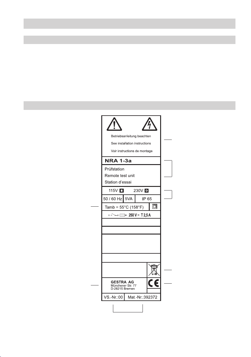
Name plate / marking
Admissible ambient temperature
2
Safety note
Equipment designation
Electrical rating
Protection
Fig. 1
Manufacturer
Disposal note
CE marking
Specification for ordering
spare parts
7
Page 8
8
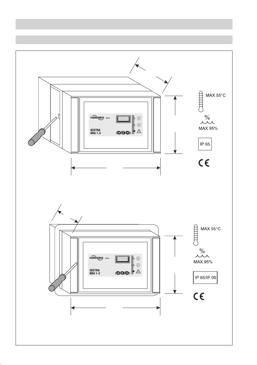
Technical Data – continued –
Dimensions NRA 1-3
Fig. 2
Test station NRA 1-3 a
137
146.7
226.5
Fig. 3
Test station NRA 1-3 e
Front panel cut-out 236x151
105
146.7
226.5
Page 9

Installation
Test station NRA 1-3a
The enclosure of the test station NRA 1-3a is designed for wall mounting. The four fixing holes are
accessible after opening the base part. For this purpose use a screwdriver with a broad blade to lever
the hinge out of the slot on the left side, see Fig. 2.
Then use suitable screws and wall plugs to fix the rear cover.
Test station NRA 1-3e
The enclosure of the test station NRA 1-3e is designed for panel mounting, panel cut-out:
236 x 151 mm. Place the equipment into the cut-out of the panel.
To unlock the hinge and swing the front panel open use a broad blade screwdriver to lever the front
panel out of the frame. Then turn the four screws for the tensioning clamps to the right until the
casing is firmly fixed in the panel cut-out, Fig. 3.
Note
Test station NRS 1-3a
After mounting the equipment you can
n connect the measuring electrodes / temperature sensor and
n set the operating mode and the number of the measuring channels (see “Commissioning”)
in a single operation with the base part open. Then close the base part and lock the left hinge.
Tools
n Screwdriver (5.5/100)
9
Page 10

10
1 2 3 4 5 1 2 3 4 5
1 2 3 4 5 1 2 3 4 5
1 2 3 4 5 1 2 3 4 5
1 2 3 4 5 1 2 3 4 5
1 2 3 4 5 1 2 3 4 5
1 2 3 4 5 1 2 3 4 5
1 2 3 4 5 1 2 3 4 5
1 2 3 4 5
1 2 3 4 5
1 2 3 4 5
1 2 3 1 2
1
0
9
8
7
6
5
4
3
2
NO
Functional Elements
E
NRA 1-3
6
5
1
2 3 4
Fig. 4
E
F
G
H
I
J
K
L
A
NRA 1-3
(Connecting side)
M
N
O
P
Q
R
S
T
C
D
Page 11

Functional Elements – continued –
Key
1 Seven-segment display
2 LED indicating steam loss
3 LED indicating banking-up of condensate
4 LED indicating malfunction in measuring electrode
5 Pushbutton for settings
6 Code switch
A Terminal for temperature sensor for system temperature
C Terminal for collective alarm
D Terminal for mains voltage
E – T Terminals for measuring electrodes
Mode 1, 2, 4 – 7
E – T Channel 1 – 16
Mode 3
E + M Channel 1
F + N Channel 2
G + O Channel 3
H + P Channel 4
I + Q Channel 5
J + R Channel 6
K + S Channel 7
L + T Channel 8
11
Page 12

12
Wiring
Connecting line of temperature sensor for detecting the temperature of the installation
Use screened three-core cable (e. g. Ölflex 110 CH, manufactured by LAPP, 3 x 0.5 mm²) for connecting
the sensor. Max. cable length between temperature sensor and test station NRA 1-3: 50 m. Connect
screen to the sensor.
Connecting line of measuring electrodes
NRG 16-19
The measuring electrode comes with a 2 m long connecting line and can be directly plugged into
the test station NRA 1-3. An extension is possible with screened two-core cable, e. g. Ölflex 110 CH,
manufactured by LAPP, 2 x 0.5 mm². Max. cable length between temperature sensor and test station
NRA 1-3: 50 m. Connect screen to the distribution substation.
NRG 16-27, NRG 16-28
Use screened five-core cable (e. g. Ölflex 110 CH, manufactured by LAPP, 5 x 0.5 mm²) for connecting
the electrode. Max. cable length between measuring electrode and test station NRA 1-3: 50 m.
Connect screen to the connecting coupler.
Wiring
NRA 1-3a
With the base part taken off:
1. Loosen the cable glands and pull the connecting lines through the glands.
2. Remove approx. 32 cm of the end insulation of the cable and the screen.
3. Connect the wires to the terminal strips (rear of base part) according to the wiring diagram and use
a cable tie for securing the cable bundle to prevent misalignment.
4. Tighten cable glands to achieve a good seal. Use sealing plugs to seal off cable glands that are not
used.
NRA 1-3e
1. Remove approx. 30 mm of the cable end insulation.
2. Connect the wires to the terminal strips (rear of base part) according to the wiring diagram.
Attention
n To protect the output relays provide the circuit with a T 2.5 A (slow blow) fuse.
n To suppress interferences provide connected contactors with RC combinations as
specified by the manufacturer.
n Install an easily accessible disconnector that serves as means of isolation from the
electrical supply near the test station (EN 61010-1).
n Label this disconnector as means of isolation for the test station.
Page 13

Wiring – continued –
1 2 3 4 5 1 2 3 4 5
1 2 3 4 5 1 2 3 4 5
1 2 3 4 5 1 2 3 4 5
1 2 3 4 5 1 2 3 4 5
1 2 3 4 5 1 2 3 4 5
1 2 3 4 5 1 2 3 4 5
1 2 3 4 5 1 2 3 4 5
1 2 3 4 5 1 2 3 4 5
1 2 3 4 5
1 2 3 1 2
1
0
9
8
7
6
5
4
3
2
NO
L
N
1 2 3 4
Tools
n Screwdriver for cross-recess head screws, size 1 and 2
n Screwdriver for slotted screws, size 2.5, completely insulated to VDE 0680
Wiring diagram for test station NRA 1-3
Class 4 (NRA 1-3)
Class 5 (NRA 1-3)
NRG 16-27/-28
Distribution
substation
Condensate
NRG 16-19
Condensate
NRA 1-3
Code switch,
white
e. g. TRG 5-63
Malfunction
*) Cable tie
Disconnector
Fig. 5
13
Page 14

14
Basic Settings
1 098765432
NO
Factory setting
Test station NRA 1-3
The test station features the following factory set default values:
n Difference of condensate temperature / plant temperature or switchpoint “Banking-up of conden-
sate”: 40 K
n Maintenance interval: 6 months (not adjustable)
n Code switch 6 Fig. 4: All switches are set to OFF.
Commissioning
Check wiring
Before commissioning please check:
Are the measuring electrodes /temperature sensor correctly wired in accordance with the wiring
diagram?
Set operating mode
Use code switch 6, Fig. 4, switches S1 – S3 to set one of the following seven operating modes.
6
Code switch, white
Mode S1 S2 S3
1 ON OFF OFF Yes
2 OFF ON OFF No
3 ON ON OFF No
4 OFF OFF ON No Steam loss 16 No temperature measurements
5 ON OFF ON No
6 OFF ON ON Yes
7 ON ON ON No
Plant
temperature
OFF OFF OFF Test
Function Channels Remark
Steam loss
Banking-up of
condensate
Steam loss
Banking-up of
condensate
Steam loss
Banking-up of
condensate
Banking-up of
condensate
Banking-up of
condensate
Banking-up of
condensate
Comparison of condensate temp.
16
and plant temperature
Only condensate temperature is
16
measured
8 No temperature measurements
No temperature measurements
16
Comparison of condensate temp.
16
and plant temperature
Only condensate temperature is
16
measured
Page 15

Commissioning – continued –
1 098765432
NO
Note
In mode 3 two measuring electrodes NRG 16-19 (one for banking-up of condensate and
one for steam loss) per measuring channel are connected together so that e. g. a float trap
can be monitored. For more information see the installation instructions for NRG 16-19,
NRG 16-27, NRG 16-28.
In mode 6 and 7 the measuring electrodes NRG 16-27, NRG 16-28 receive the measure
ments of the condensate temperature only from the integrated temperature sensor.
Establishing the number of measuring channels
Use code switch 6 Fig. 4, switches S4 – S7 to set the number of measuring channels.
The switches S8 – S0 must remain in the OFF position.
6
Code switch, white
S4 S5 S6 S7 Channels S4 S5 S6 S7 Channels
OFF OFF OFF OFF 1 OFF OFF OFF ON 9
ON OFF OFF OFF 2 ON OFF OFF ON 10
OFF ON OFF OFF 3 OFF ON OFF ON 11
ON ON OFF OFF 4 ON ON OFF ON 12
OFF OFF ON OFF 5 OFF OFF ON ON 13
ON OFF ON OFF 6 ON OFF ON ON 14
OFF ON ON OFF 7 OFF ON ON ON 15
ON ON ON OFF 8 ON ON ON ON 16
-
Note
If the settings of S1 – S7 are changed during operation, the new settings will only be
accepted by the test station after the supply voltage has been switched off and on.
Switching on supply voltage
Switch on supply voltage. The seven-segment display and the LEDs will be tested, i. e. all segments
and LEDs will be illuminated/flashing.
15
Page 16

16
Operation, Alarm and Test
E
Specification of keys and displays
Fig. 6
Function of keys
Key 1: Reduce value –, browse
Key 3: Increase value +, browse
Key 2 (E): Press briefly: Call up/Execute menu // Continue / Save settings
Key 2 (E): Press longer: Return to menu, cancel input
Key 1 + 3: Press longer: Reset/Delete values (e. g. alarm list + maintenance interval)
LEDs 1 – 3
LED 1: Steam loss
LED 2: Banking-up of condensate
LED 3: Measuring electrode NRG 16-27 defective (short circuits, parting of a cable).
Measuring electrodes NRG 16-19 are not monitored.
Key to codes on seven-segment display
Code Meaning
The following codes can appear on the seven-segment display even if no key is being pressed:
SYS System SYS changes with plant temperature in °C
E.01
E.02
E.03 Error Maintenance interval (6 months) elapsed
C.01 – C.16 Channels 1 - 16
If the E key is pressed:
HIS History Alarm list detailing old alarms
InT Interval Remaining time of maintenance interval
CAL Calibration Channel calibration in mode 2
dtC (mode 2, 7)
dtS (mode 1, 6)
tSt Test LEDs and all segments are illuminated
ALL All channels Channel selection when calibrating / setting
C.01 – C.16 Channels 1 - 16
don Done Confirmation of input when setting parameters
clr Clear Confirmation of clear command (interval, alarm)
Error Incorrect configuration due to inadmissible code switch setting
Error In mode 2 and 7 the settings for banking-up of condensate is not finished
Indication of measuring channel
Delta TC Admissible deviation from condensate temperature in steam trap
Delta TS Admissible deviation from plant temperature
Indication of measuring channel
Page 17

Operation, Alarm and Test – continued –
Start
Mode 1, 6: After the mains voltage has been switched on and the display test has been finished the
system temperature, error messages and current alarms will be indicated.
Mode 2 to 5 and 7: After the mains voltage has been switched on and the display test has been finished
error messages and current alarms will be indicated.
For more information on the codes HIS, Int and tSt see section “Alarm list, Maintenance interval and
Test”, mode 1 to 7.
Setting banking-up of condensate, mode 1 and 6
Key E
SYS / °C
briefly →
← longer
(1)
(1)
HIS
Keys
↓ (3) ↑
InT
Keys
↓ (3) ↑
dtS
Key E
briefly →
← longer
(1)
ALL
Keys
↓ (3) ↑
C.xx
Key E
briefly →
← longer
Key E
briefly →
← longer
Change
temperature
Keys (1),(3)
Change
temperature
Keys (1),(3)
Key E
briefly →
Key E
briefly →
don
←
dtS
don
←
C.xx
The precondition for this operating mode is:
n the use of the measuring electrodes NRG 16-27, NRG 16-28 (with integrated condensate
temperature measurement at the steam trap)
n the use of a separate temperature sensor for the measurement of the system/(plant) temperature
With the parameter dtS the difference between the condensate temperature in the steam trap and the
plant temperature can be modified either globally for all steam traps (ALL) or for each individual trap
(C.xx). The factory set default value is 40 K. The value can be changed in increments of 1 K up to a max.
limit of 100 K.
17
Page 18

18
Operation, Alarm and Test – continued –
Setting banking-up of condensate, mode 2 and 7
y y y
Serial
poll
The precondition for this operating mode is:
n the use of the measuring electrodes NRG 16-27, NRG 16-28 (with integrated condensate
temperature measurement at the steam trap)
With the parameter dtC the factory set difference of 40 K between the temperature measured at the
steam trap and the switchpoint “Banking-up of condensate”. The value can be changed in increments
of 1 K up to a max. limit of 100 K.
In the parameter mode CAL the condensate temperature from all steam traps is polled, the difference
dtC is subtracted and the result saved.
Starting from the parameter mode ALL, the switchpoint “banking-up of condensate” can be adjusted in
increments of 5 K for each individual steam trap (C.xx) in order to match the settings optimally to the
operating conditions.
Key E
briefly →
← longer
(1)
(1)
(1)
HIS
Keys
↓ (3) ↑
InT
Keys
↓ (3) ↑
CAL
Keys
↓ (3) ↑
dtC
Key E
briefly →
← longer
Key E
briefly →
← longer
ALL
Keys
(1)
↓ (3) ↑
C.xx
Change
tempera-
ture
Keys (1), (3)
Key E
briefly →
Key E
briefly →
← longer
Key E
briefly →
Temperature
auto poll
Change
temperature
Keys (1), (3)
don
←
dtC
auto →
Key E
briefly →
don
←
CAL
don
←
C.xx
Page 19

Operation, Alarm and Test – continued –
E
Alarm messages
Fig. 7
The alarm messages “Banking-up of condensate”, “Steam loss” and “Malfunction in electrode” (short
circuit, parting of cable) will be indicated in the particular operating mode by the LEDs 1 – 3 and the
output relay for the collective alarm is energized.
In addition, the seven-segment display shows the number of the faulty steam trap (C.xx). If more than
one steam trap are faulty the numbers are indicated one after the other.
Once the cause for the alarm is eliminated, the message is entered into the alarm list.
Alarm list, maintenance interval and test, mode 1 to 7
SYS /
y y y
Serial
poll
Alarm list HIS
Use keys 1 and 3 to browse through the list. The respective alarm messages are indicated by the
associated LEDs 1 – 3. If you want to delete a list entry press and hold down the keys 1 and 3, the
message clr appears, the entry is deleted and the cursor goes to the next entry.
Key E
briefly →
← longer
(1)
(1)
HIS
Keys
↓ (3) ↑
InT
Keys
↓ (3) ↑
tSt
Key E
briefly →
← longer
Key E
briefly →
← longer
Key E
briefly →
← longer
Display,
keys (1),(3)
=
browse
Display
Display
LEDs +
segments
Keys
(1) + (3)
longer →
← auto
Keys
(1) + (3)
longer →
← auto
Key E
briefly →
clr
clr
don
←
tSt
19
Page 20

20
Operation, Alarm and Test – continued –
Alarm list, maintenance interval and test, mode 1 to 7 – continued –
Maintenance interval InT
The paramter mode InT shows the remaining time of the maintenance interval in days. Hold down the
keys 1 and 3 to reset the maintenance interval, the message
previous display.
Test tSt
The parameter tSt checks the segments of the seven-segment display and the LEDs 1 – 3. After the
test the system returns to the parameter tSt.
Note
If the key E is used to select a parameter but then no key is pressed, the test station
returns to the start window after 10 seconds.
Malfunctions
The following malfunctions can be indicated by the seven-segment display:
Error code Error Remedy
E.01 Incorrect configuration set by code switch
E.02
E.03 Maintenance interval elapsed
E.04 Temperature in test station is too high Check installation of test station
In mode 2, 7 the setting “Banking-up of
condensate” has not been finished
clr appears and the system returns to the
Check and correct configuration.
The test station accepts the new settings only after
switching the supply voltage off and on again
Finish the setting “Banking-up of condensate”
Remove and clean measuring electrodes.
Reset the maintenance interval in the parameter
mode InT
If faults occur that are not listed above or cannot be corrected, please contact our service centre or
authorized agency in your country.
Page 21

Decommissioning
NRA 1-3
First disconnect the supply voltage and pull the cable out of the cable gland. Then disconnect the
measuring electrodes and pull the electrode cables out of the cable glands.
De-install the test station.
Danger
The terminal strips of the test station NRA 1-3 are live during operation.
This presents the danger of electric shock.
Always cut off power supply before mounting, removing or connecting the terminal
strips!
Disposal
NRA 1-3
De-install the test station NRA 1-3 and separate the waste materials, using the materials
specifications.
Dispose of electronic components (boards) separately.
For the disposal of the test station observe the pertinent legal regulations concerning waste disposal.
21
Page 22

22
Annex23For your Notes
Declaration of Conformity
We hereby declare that the test station NRA 1-3 conforms to the following European Directive:
n
LV guideline 73/23/eec version 93/68/eec
n
EMC guideline 93/68/eec
This declaration is no longer valid if modifications are made to the equipment without consultation
with us.
Bremen, 7th July 2006
GESTRA AG
Head of Design Dept
Dipl. Ing. Uwe Bledschun
(Academically qualified engineer)
Quality Assurance Manager
Dipl. Ing. Lars Bohl
(Academically qualified engineer)
Page 23

Page 24

Agencies all over the world:
www.gestra.de
GESTRA
España
GESTRA ESPAÑOLA S.A.
Luis Cabrera, 86-88
E-28002 Madrid
Tel. 00 34 91 / 5 15 20 32
Fax 00 34 91 / 4 13 67 47; 5 15 20 36
E-mail: aromero@flowserve.com
Great Britain
Flowserve Flow Control (UK) Ltd.
Burrel Road, Haywards Heath
West Sussex RH 16 1TL
Tel. 00 44 14 44 / 31 44 00
Fax 00 44 14 44 / 31 45 57
E-mail: gestraukinfo@flowserve.com
Italia
Flowserve S.p.A.
Flow Control Division
Via Prealpi, 30
l-20032 Cormano (MI)
Tel. 00 39 02 / 66 32 51
Fax 00 39 02 / 66 32 55 60
E-mail: infoitaly@flowserve.com
Polska
GESTRA POLONIA Spolka z.o.o.
Ul. Schuberta 104
PL - 80-172 Gdansk
Tel. 00 48 58 / 3 06 10 -02 od 10
Fax 00 48 58 / 3 06 33 00
E-mail: gestra@gestra.pl
Portugal
Flowserve Portuguesa, Lda.
Av. Dr. Antunes Guimarães, 1159
Porto 4100-082
Tel. 0 03 51 22 / 6 19 87 70
Fax 0 03 51 22 / 6 10 75 75
E-mail: jtavares@flowserve.com
USA
Flowserve GESTRA U.S.
2341 Ampere Drive
Louisville, KY 40299
Tel.: 00 15 02 / 502 267 2205
Fax: 00 15 02 / 502 266 5397
E-mail: dgoodwin@flowserve.com
GESTRA AG
P. O. Box 10 54 60, D-28054 Bremen
Münchener Str. 77, D-28215 Bremen
Telephone +49 (0) 421 35 03 - 0
Fax +49 (0) 421 35 03 - 393
E-Mail gestra.ag@flowserve.com
Internet www.gestra.de
818678-00/806cm · 2006 GESTRA AG · Bremen · Printed in Germany
24
 Loading...