

Page 1

GESTRA Steam Systems
LRR 1-40
Installation Instructions 818527-00
TDS Control Unit LRR 1- 40
Page 2

Contents
Page
Important Notes
Usa ge for the intended purpose.......................................................................................6
Safety note.......................................................................................................................6
ATEX (Atmosphères Expl osibles)....................................................................................7
Danger note.....................................................................................................................7
Explan atory Notes
Scope of supply .......................................... .....................................................................7
Description.......................................................................................................................8
Function...........................................................................................................................9
Technical data................................................................................................................10
Name plate.....................................................................................................................13
Installation
Control unit LRR 1-40....................................................................................................13
Tools ..............................................................................................................................13
Wiring
Bus cable.......................................................................................................................14
Change baud rate ........ ..................................................................................................15
Wir e terminal strip....................................... ...................................................................15
Wir ing diagram LRR 1-40..............................................................................................16
Wir ing diagram for CAN bus ..........................................................................................17
Tools ..............................................................................................................................18
Basic Settings
CAN bus.........................................................................................................................19
NodeID...........................................................................................................................19
Factory setting ...............................................................................................................20
Commissioning
Start ...............................................................................................................................21
Performance of the continuous blowd o wn valve............................................................21
2
Page 3

Conte nts
Page
Operation
Normal operation ...........................................................................................................22
Continuous boiler blowdown..........................................................................................22
Intermittent boiler blowdown..........................................................................................22
Stand-by operation ........... .............................................................................................23
24 hr purging pulse.................................................................................... ....................23
MAX limit / MIN limit.......................................................................................................24
MAX limit / MIN limit=Automati c intermittent boiler blowdown ......................................24
Performance test ...........................................................................................................25
Please note when using the equipment as conductivity limiter......................................25
Performance test for relays 1 and 4...............................................................................26
System Faults
Causes...........................................................................................................................27
Test................................................................................................................................27
Systematic malfunction analysis....................................................................................28
Fault finding list for troubleshooting system faults..................................... ....................29
Action against high frequency interference....................................................................30
Replace controller..........................................................................................................31
Malfunctions
Fault finding list for troubleshooting ...............................................................................32
Annex
Factory setting of n ode IDs............................................................................................33
Establishi ng / changing node ID ....................................................................................33
Table Node ID........ ........... .......... .......... ........... .......... ........... .......... ........... .......... ..........34
Change factory setting...................................................................................................34
Declaration of conformity...............................................................................................35
Examples of installation.................................................................................................3 6
3
Page 4
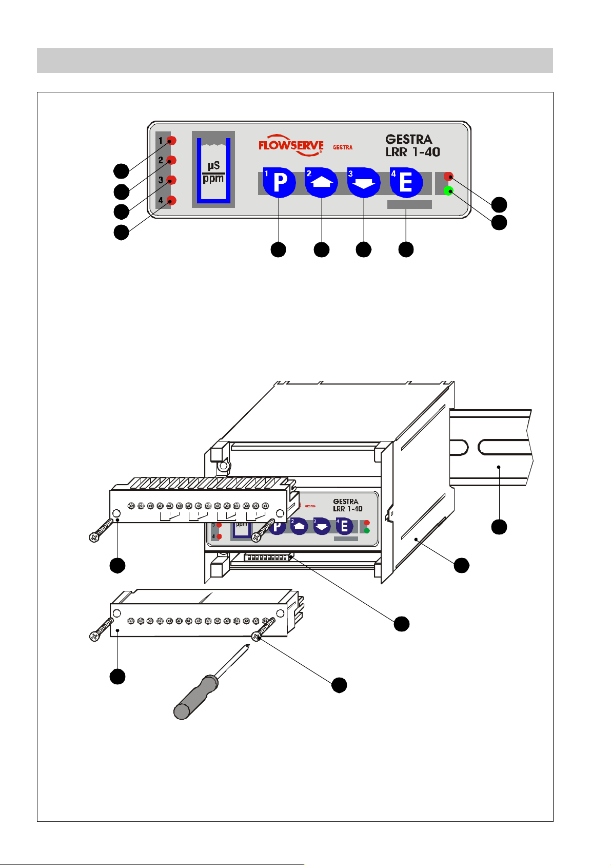
Functional Elements
1
2
3
4
Fig. 1
5 6 7
Test
8
10
9
Fig. 2
1
LNN
1
2
A
+-C
CS
LH
123456789101112131415
B
2716 17 18 19 20 21 22 23 24 25 26 28 29 30
MAX
12
P
Test
F
E
D
C
4
Page 5

Key
1
LED 1 (MAX)
2
LED 2 (Valve closed)
3
LED 3 (Valve open)
4
LED 4 (MIN)
5
Program button for switching between oper ating and parameterising mode
6
Increase button
7
Decrease button
8
Enter button / test mode
9
Green LED "Power"
Red LED "Status CAN bus"
10
A
Upper termina l strip
B
Lower termina l strip
C
Fixing screws (cross recess head screws M4)
D
Code switch
E
Casing
F
Supporting rail type TH 35, EN 60715
5
Page 6

Important Notes
Usage for the intended purpose
Use blowdown controller LRR 1-40 only in conjunction with conductivity electrode
LRG 16-40 and an operating & display unit type URB or SPECTORcontrol for detecting
and monitoring electrical conductivity in liquids.
Note that the application of the control unit LRR 1-40 for conductivity limiting purposes or
cont inuous boiler blowdown is only permissible if it is us ed in conjunction with the
conductivity elec trode LRG 16-40 and an operating & display unit type URB or
SPECTORcontrol.
To guarantee a trouble-free operation observe the requi rements made on water quality
as specified in the pertinent TRD and EN regulations.
Any type of use differing from the usage described a bove must be considered as
improper. The resulting risk will have to be borne by the user alone. The manu facturer
hereby expressly r ejects any claims for any damage resul ting from improper usage.
Safety note
The equipment must only be installed and c ommissioned by qualified and competent
staff.
Retrofitting and maintenance work must only be performed by qualified staff who through adequate training - have achieved a recognised level of competence.
For installation, removal, commissioning, operation and maintenance, every person who
works with the equipment must have read and understood the complete installation
manual. Furthermore, respon sibilities must have been defined clearly and
unambi guously and must be adhered to.
Usage of the equipment for the intended purpose includes compliance with the rules and
notes in these installation instructions for installation, removal, commissioning, operation
and mai ntenance.
The operating company must ensure that, whenev er the equipment is being operated, it
is in perfect condition.
Working methods that jeopardise safety must not be used!
6
Page 7

Important Notes – conti nued –
ATEX (Atmosphères Explosibles)
According to the European Directive 94/9/EC the equipment must not be used in
potentially explosive areas.
Danger note
Danger
The term inal strip of the control equipment is live during operation. This
presents the danger of electric shock!
Cut of f pow er supp l y before attaching or detaching the terminal strip of the
control e quipment!
Explanatory Notes
Scope of supply
LRR 1-40
1 Control unit LRR 1-40 (plug-in unit in plastic case)
1 Terminating resistor 120Ω
1 Installation manual
7
Page 8

Explanatory Notes – continued –
Desc r ip tio n
As the boil er water evaporates, the concentration of non-volatile dissolved solids (TDS)
left behind in the boiler increases over time as a function of steam consumption. If the
TDS (= total dissolved solids) concentration exceeds the limit defined by the boiler
manufactu rer, foaming and priming occurs as the density of the boiler water increases,
resulting in a carry-over of solids with vapour into steam lines and super heaters. As a
consequence, the operational safety is impaired and severe damage to boiler and tubes
may occur.
In addition, excess phosphate (due to phosphate treatment) or concentrated residual
hardness particles form accumulated sludge that deposits on heating surfaces and on the
bottom of the steam boiler. The insulating layer formed by these deposits can cause the
boiler metal to become overheated, resulting in a dangerou s situation since the metal is
now subjected to design pressure at an elevated temperature.
The TDS control unit LRR 1-40 in conjunction with the conductivity electrode LRG 16-40
and the operating & display unit type URB or SPECTORcontrol ensure efficient boi ler
blowdown.
The quality of the boiler water is monitored with the aid of:
■ Conductivity control / limitation,
■ Continuous boiler blowdown control,
■ Automatic intermittent blowdown control.
The TDS controller LRR 1-40 can be used in combination with the conductivity electrode
LRG 16-40 and an operating & display unit type URB or SPECTORcontrol for TDS
control (c onductivity limitation) and continuous boiler blowdown in steam boilers and
(pressuris ed) hot-water plants.
The data exchange between the control unit LRR 1-40, the conductivi ty electrode
LRG 16-40 and the operating device as well as further equipment is effected via CAN bus
according to ISO 11898, using the CANopen protocol.
8
Page 9

Expl an ato ry No tes – co ntinue d –
Function
The conductivity electrode LRG 1-40 sends at regular intervals data telegrams via CAN
bus to the control unit LRR 1-40.
The data telegram of the conductivity electrode LRG 16-40 contains the following data:
■ Conductivity reading (actual value X), based on 25°C
■ Temperatur e of boiler water,
■ Alarm: Internal cable monitoring signals malfunction(s),
■ Alarm: Temperature sensor for boiler water is defective,
■ Alarm: Excessively high temperature in terminal box.
All transmitted process data are continuously evaluated by the control unit and assigned
to the control range and the respective switch points.
If the associated conductivity electrode interrupts the data transmitting cycle, an alarm
message is given and a visual signal is indicated by the display of the operating device.
Use operati ng device URB or SPECTORcontrol to configure, parameterize, operate and
show the available parameters of the conductivity electrode. The control unit LRR 1-40
can only test the ener gizing/de-energizing of the relays for the limit values.
The control unit features the following functions:
■ Use as 2-position controller for the control of a conti nuous blowdown valve,
■ Use as 3-position proportional stepping controller for the control of a continu ous
blowdown valve with feedback potentiometer,
■ Triggering of daily purgin g pulse (24h) to actuate the continuous blowdown valve,
■ De-activation of control function during stand-by operation of steam boiler,
■ Alarm signal in the event of a malfunction in the conductivity electrode,
■ Max. limit alarm for conductivity limiting,
■ Min. limit alarm or
■ Automatic blowdown c ontrol with timed actuation of the intermittent blowdown valve,
■ Analog actual value output (4-20mA) for external conductivity indication (optional).
9
Page 10

Expl an ato ry No tes – co ntinue d –
Technical data
Type approval no.
TÜV.WÜL.02-007
EG BAF-MUC 02 05 103881 003
Input/Output
Interface for CAN bus to ISO 11898 CANopen.
Inputs
CAN bus interface with power supply 18-36V D C, short circuit protected.
Analog control input for indicating valve position via feedback potentiometer 1000Ω,
angle of rotation 320°, supply voltage 5V DC.
Voltage input 18-36V AC (50/60 Hz) or DC for external com mand:
Control OFF, valve CLOSED, intermittent blowdown OFF. With DC protected against
polarity reversal.
Outputs
Four volt-free relay contacts.
Max. contact rating with a s witching voltage of 24V AC/DC, 115V AC and 230V AC:
resistive / inductive 4A.
Contact material AgNi 0.15.
Current output 4-20mA as actual va lue output, max. load 750Ω (optional).
Conductivity measuring range with actual value output 4-20mA
Beginning of measuring range End of measuring range
ppm* µS/cm * mA ppm* µS/cm * mA
10 20 20
50 100 20
100 200 20
250 500 20
0.25 0.5 4
500 1000 20
1000 2000 20
3000 6000 20
6000 12000 20
* based at 25°C
10
Note
The electrical conductivity is measured in µS/cm. For ppm (parts per million)
use the f ollowing conversion:
1µS/cm = 0.5ppm.
Page 11

Expl an ato ry No tes – co ntinue d –
Technical data - c ontinued -
Indicators and adjustors
Four pushbuttons as operating elements.
Four LED s for indicating the operating modes.
One green LED for power suppl y.
One red LE D for sta tus indication of CAN bus.
One 10-pole code switch for setting node ID and baud rate.
Setpoint W
Adjustable within the measuring range between the adjusted MIN/ MAX limi ts.
Control range (configuration as proportional controller)
Beginning: 0.5 x setpoi nt W up to 1.5 x setpoint W
Dead band (con figuration as proporti onal controller)
Based on setpoint W:
Setpoint W below 2000 µS/cm (1000 ppm) DB = 3%
Setpoint W above 2000 µS /cm (1000 ppm) DB = 1%
Switching hysteresis of controller output (configuration as 2-position controller)
Adjustabl e between 1 and 25% of the adjus ted setpoint.
Operating position of the continuous blowdown valve
Adjustabl e as a function of the continuous blowdown valve.
Proportion al band Xp
From 1 to 150% relative to setpoint W (configuration as proportional controller),
adjustable, 0% (configuration as 2-position contr oller).
MIN/MAX limits
Measuring range up to 200 µS/cm (100 ppm):
MIN limit adjustable between 0.5 µS/cm (0.25 ppm ) and MAX limit
- 2 µS/cm (1 ppm),
MAX limit adjustable between 200 µS/cm (100 ppm) and MIN limi t
+2 µS/cm (1 ppm).
Other measuring ranges:
MIN limit adjustable between 0.5 µS/cm (0.25 ppm) and MAX limit
-20 µS/cm (10 ppm),
MAX limit adjustable between end of measuring range and MIN limit
+20µS/cm (10ppm).
MIN/MAX limits,
Switching hystereses
MIN limit: +1% of the adjusted MIN limit,
MAX limit: -1% of the adjusted MAX limit.
11
Page 12

Expl an ato ry No tes – co ntinue d –
Technical data - continued -
24 hr purging pulse
Forced opening of the continuous blowdown valve every 24 hours, adjustable.
Automatic intermittent blowdown
Interval time (duration of break): 1-120 hours, adjustable in steps of one hour.
Duration of pulse: 1-60 se conds, adjustable in steps of one second.
Mains supply
230V +10 / -15%, 50-60 Hz
115V +10 / -15%, 50-60 Hz (optional)
24V +10 / -15%, 50-60 Hz (optional)
Power consumption
10V A
Protection
Casing: IP 40 to EN 60529,
Terminal strip IP 20 to EN 60529.
Admissi ble ambien t temperatur e
0-55°C
Casing
Design: Case made of insulating material, with pl ug-in terminals
Casing material: Base: black polycarbonate; front panel: grey polycarbonate,
Number of terminals: 30
Cross section of connector: 1x4.0 mm2 solid or
1x 2.5 mm2 stranded wire with sleeve to DIN 46228 or
2x1.4mm2 stranded wire with sleeve to DIN 46228,
Fixing of conductor: Plus/ Minus terminal screw M 3.5,
Term inals with s elf-lifting wire protection.
Terminal strip: Separately detachable,
Fixing of casing: Mounting clip on supporting rail TH 35, EN 60715.
Weight
Approx. 0.8 kg
12
Page 13

Expl an ato ry No tes – co ntinue d –
A
Nam e plat e
Safety note
Power rating
Input characteristics
Fuse
Manufacturer
Fig. 3
Betriebsanleitung
beachten
Se e in stalla ti on
instructions
Voir instructions de
montage
18-36 V DC
IN / OUT: CAN-Bus
S
12345 78
S
24V
CAN-BUS
DC
TÜV.WÜL. 02 - 007
250 V ~ T 2,5 A
GESTRA AG
Münchener Str.77, D-28215 Bremen
C
C
L
Steuergerät
Con tr ol device
ppareil de commande
230 V
115 V
24 V
++
H
24V AC/DC
stand-by
Spare part specification
50 / 60 Hz 5 VA
IP 40 (IP20)
1110912 1514
S
+
US Pat. 5 805 05 2
VS.-Nr.:
13
S
-
+
-
X ext
4-20 mA
M
Mat.Nr.:
1716
LN
0525
Equipment
designation
Mains supply
Protection
Pressure/
temperat ure range
Node-ID
Wiring diagram
CE marking
Installation
Control unit LRR 1- 40
The control unit LRR 1-40 is installed in a control cabinet on a supporting rail type
TH 35, EN 60715.
1. Clip casing with the upper mounting rail onto the support rail . When the
casing snaps into place a clicking sound can be heard.
E F
E
2. Make sure that the white mounting slide is correctly located.
3. Align the control unit horizontally on the support rail .
F
Tools
■ Screwdriver, size 5.5/100
F
13
Page 14

Wiring
Bu s cable
Note that screened multi-core twisted-pair control cable is require d as bus line, e.g.
UNITRONIC® BUS CAN 2x 2x...mm² or RE-2YCYV-fl 2x2x...mm².
The baud rate (data transfer rate) dictates the cable length between the bus nodes, and
the conductor size dictates the total power consumption of the sensor.
S 8 S 9 S 10 Baud rate Cable length
OFF ON OFF 250 125 m
Factory setting
ON ON OFF 125 kBits/s 250 m 2x 2x0.5
OFF O FF ON 100 kBit s/s 33 5 m 2x2 x0.75
ON OFF ON 50 kBits/s 500 m
OFF ON ON 20 kBits/s 1000 m
ON ON ON 10 kBits/s 1000 m
The baud rate is set via code switches (S8 to S10). Default factory setting of control
D
Number of pairs and
conductor size [mm²]
2x2x0.34
avai lable on de mand (d epends
on bus configuration)
unit LRR 1-40: baud rate 250kbit /s (cable length 125m).
For longer cable lengths reduce baud rate ac cordingly. Make sure that all bus nodes
feature the sam e settings.
UNITRONIC® is a registered trademark of LAPP Kabelwerke GmbH, Stuttgart.
14
Page 15

Wi r i ng – con tinue d –
Chan ge b a ud r at e
1. Remove lower terminal strip .
B
2. The terminal strip can be unplugged after u ndoing the right and the left fixing
screws .
3. Set the baud rate via code switches S8 to S10 as specifi ed in the previous table
C
D
under "Baud rate" by using a thin blade screwdriver.
4. Re-insert terminal strip and fasten the fixing screws .
B C
Wire ter m in al s trip
Wire the terminal strips in accordance with the wiring diagram.
A B
Only terminal 3 require s a screen.
Note
The max. baud rates and cable lengths indicated above ar e based on
empirical values obtained by GESTRA. In certain cases it may be necessary
to reduce the baud rate in order to ensure operational safety.
The design and preparation of the data cable is an important factor for the
electrom agnetic compatibility (EMC) of the equipment. Wiring should
therefore be carried out with special care.
15
Page 16

Wi r i ng – con tinue d –
Wiring diagram LRR 1- 40
MAX limit
Safety circuit
L
N
CLOSEDLOPEN
L
L
MIN limit
L
S
24V DC
CAN bus
Twisted pair
cables
17 18 19 2 0 21 22 23 249251026
LNN
-
1
1
C
LH
2345678
+
CS
23 25
Potentiometer
Contact in burner control,
if stand-by function is desired.
2716
Test
11 12281329143015
Actual value output
4-20mA (option)
Terminating resisto r
120Ω
Fig . 4
Fig. 5
16
N 25 23 12
123
24V AC/DC
Observe polarity
with D C!
11
10
5V DC
Terminal 7/8
Voltage input 24V
AC/DC for external comman d
contact closed
Control OFF, valve CLOSED,
inte rm itten t bl owdown OFF [St and-by]
(Might come from bus supp ly.)
Feedback potentiometer 1000Ω
Continuous blowdown control
= Valve OPEN 25
= Valve CLOSED 23
Actuator
Continuous blowdown valve BAE 36-1
Page 17

Wi r i ng – con tinue d –
Wiring diagram for CAN bus
The following wiring diagram serves as an example:
Central
earthing point
CEP
Operati ng
device URB
Contr ol unit
LRR 1-40
Control unit
...
Conductivity
electro de
LRG 16 -40
Level
electrode
NRG ...
Terminating resistor
120Ω
Fig. 6
Attention
■ Wire equipment in series. Star-type wiring is not permitted!
■ Link screens of bus cables such that electrical continuity is ensured and
connect them once to the central ea rthing point (CEP).
■ To protect the switching contacts provide the circuit with a T 2.5A or 1A
fuse (TRD 604, 72 hours operation without constant supervision).
■ If two or more system components are connected in a CAN bus system,
provide the first and the last device with a term inating resistor of 120Ω
(terminal CL/CH Fig. 6).
Voltage supply CAN data line
Terminating resistor
120Ω
■ The CAN bus system must not be interrupted during operation.
In the event of an interruption a malfunction ala rm is raised.
If the control unit has to be replaced, detach the terminal strip (Fig. 2).
Before taking the CAN bus line from the terminal strip, mak e sure that all
connected system components are out of service.
17
Page 18

Wi r i ng – con tinue d –
Wiring diagra m f or C A N b us – continued –
Note
■ Connect screens only to the specified terminals.
■ The loop resistance must be below 10Ω.
■ The rated voltage is indicated on the name plate.
■ When switching off inductive loads, voltage spikes are produced that may
impair t he operation of control and measuring systems. Connected
contactors must therefore be provided with suppressors such as
RC-combinations.
■ Even in corre ctly wire d systems h igh freq uency int erference caused by th e
installation can occur, leading to system outages and malfunction alarms.
For m ore information on malfunctions see “Fault finding list for
troubles hooting system faults“ on page 32.
Tools
■ Screwdriver for slotted screws, size 2.5, completely insulated according to
DIN VDE 0680-1.
■ Screwdriver for cross-recess head screws , size 2
18
Page 19

Basic Setting s
CAN bus
All devices (level, conductivity) are interconnected via CAN bus. The CANopen protocol
is used for the data exchange between the equi pment groups. All devices have an
electronic "address" - the nod e ID. The four-core bus cable serves as power supply and
data high way for high-speed data ex change.
The CAN address (node ID) can be set between 1 and 123.
The control unit LRR 1-40 has already been configured at our works for operation with
other GESTRA components and can be used straight away without having to set the
nodeID.
If several identical systems are to communicate in a CAN bus network, allocate a different
nodeID for each system.
Please observe the foll owing “Table Node ID“.
Node ID
Should it be necessary to establish other node IDs please take the interdependence of
the equip ment into consideration and assign the node IDs for the individual group
components according to the following table:
Reserved LRR 1-40 LRG 16-40 Reserved
X - 1 X X +1 X +2
50 51 Factory setting
reserv ed area
19
Page 20

Ba sic S et t ing s – continued –
Fa ctory se ttin g
The control unit LRR 1-40 features the following factory set default values:
Control parameters
■ Setpoint W: 5000 µS/cm
■ Switching hysteresis of controller output (configuration as 2-position controller): 10%
■ Operating position of continuous blowdown valve: 8%
■ Propo rtional band Xp: 0%
■ MAX (Hi) switchpoint): 7000 µS/cm
■ MIN (Lo) switchpoint: 1000 µS/cm
■ Automatic intermittent blowdown: Off
■ 24-h Purging pulse: Off
System settings
■ Baud r ate: 250 kbit/s (125m bus cable length)
■ N ode ID: 5 0
Enter the assigned node ID on the name plate.
Danger
The terminal strips of the control equipment are live during operation.
A B
This presents the danger of electric shock!
Cut off the power suppl y to the equipment before dismantling it or before
removing the terminal strips and the code switch .
A B D
20
Page 21

Commissioning
St art
Apply mains voltage.
LED 1-4 are flashing r apidly.
LED "Power" is illuminated.
Test
LED 1-4 go out after a short period of time.
Then the equipment sw itches either to normal operating mode or alarm mode.
Note
Malfunctions that occur during the commissioning procedure and the
correspondi ng corrective actions are described in the chapters
"Malfunctions" and "System Faults".
Performance of the continuous blowdown valve
The continuous blowdown valve is motored into the CLOSED position and then into the
OPERATING position or the control position.
Only applic able if the 24 hour purging was activated:
The continuous blowdown valve is operated for
2 minutes. T he valve opens and the LED 3 is
flashing.
Once the adjusted time has elapsed LED 3 goes out.
Test
The continuous blowdown valve is then closed for
2 minutes.
LED 2 is flashing.
Then the continuous blowdown valve is motored into
the OPERATING position or into the required control position.
Note
Since the MIN limit is not yet activated during commissioning, LED 4 or 1 is
flashing rapidly for about 60 seconds (see MIN limit).
Test
21
Page 22

Operation
Normal operation
LED "Power" is illuminated.
LEDs 1 - 4 are not illuminated, the conductivity
electrode is immersed.
Continuous boiler blowdown
LED "Power" is illuminated.
LED 2 is flashing while the continuous blowdown
valve is closing.
LED 3 is flashing while the valve is opening.
Note
Test
Test
LEDs 2 and 3 go out once the valve position dictated by continuous
blowdown control is reached.
Intermittent boiler blowdown
Only applicab le if Automatic Intermittent Blowdown Control was activated:
Upon application of mains voltage the timed intermittent blowdown interval (time between
intermittent blowdowns) is started.
During the time-c ontrolled blowdown pulse the automatic intermittent boiler blowdown
takes place:
LED "Power" is illuminated.
LED 4 is lit during intermittent blowdown and relay
contact 4 is closed. The intermittent blowdown valve
Test
opens .
Note
22
LED is not lit during the timed interval between intermittent boiler blowdowns.
Relay contact 4 is open, the intermittent blowdown valve is closed.
Page 23

Operatio n – continu ed –
Stand-by operation
To avoid loss of water , the continuous blowdown control and the automatic boiler
blowdown (if activated) can be de-activated during stand-by operation or when the firing
is switched off. An external control command (see wiring diagram) triggers off the signal.
LED "Power" is illuminated.
The continuous blowdown valve is motored into the
CLOSED position.
LED 2 is flashing and LED 3 is illuminated during the
stand-by operation.
The MIN/MAX limit and the monitoring function remain active during stand-by operation.
After the equipment switches back to normal operation the continuous blowdown valve is
motored into the OPERATING position or the control position. In addition an intermittent
blowdown pulse is tr iggered off (provided that automatic intermittent boiler blowdown has
been activated and the pulse durati on has been s et).
Test
24 hr purging pulse Only applicable if the 24 hour purging pulse was activated:
To prevent blocking of the continu ous blowdown valve a purging pulse is set off upon
application of the mains voltage.
LED "Power" is illuminated.
The continuous blowdown valve is operated and
opened for 2 minutes.
Test
LED 3 is flashing.
Once the adjusted time has elapsed LED 3 goes out.
The continuous blowdown valve is then closed for
2 minutes, LED 2 is flashing.
Then the valve is motored into the OPERATING
Test
position or into the required control position.
This process is repeated every 24 hours. Duri ng stand-by operation the ti me interval
continues without triggering off the purging pulse. Note that during the purging process
the MIN limit is not ac tive.
23
Page 24

Operatio n – continu ed –
MAX limit / MIN limit
Only applicable if:
■ Relay contact 1 (feedback LED 1) works as switching output for MAX limit
■ Relay contact 4 (feedback LED 4) works as switching output for MIN limit
LED 1 lights up once the set MAX limit is reached.
Relay contact 1 opens (safety circuit).
LED 1 goes out once the value falls below its limit.
Test
Relay contact 1 closed.
LED 4 lights up once the set MIN limit is reached.
Relay contact 4 opens.
LED 4 goes out once the value exceeds its limit.
Test
Relay contact 4 closed.
MAX limit / MIN limit =Automatic intermittent boiler blowdown
Only applicable if:
■ Relay contact 1 (feedback LED 1) works as switching output for MAX limit and MIN limit
■ Relay contact 4 (feedback LED 4) works as switching output for automatic intermittent
boi ler blowdown
LED 1 lights up once the set MAX or MIN limit is
reached. Relay contact 1 opens (safety c ircuit).
LED 1 is not lit if the actual value is between the MIN
Test
and MAX limit. Relay contact 1 closed.
LED 4 is lit during intermittent blowdown and relay
contact 4 is closed. The intermittent blowdown valve
opens .
LED 4 is not illuminated during the time b etween
Test
intermittent blowdown. Relay contact 4 is open, the intermittent blowdown valve is closed.
Note
The MIN limit is activated approx. 60 seconds after the mains voltage has
been appl ied. During this time LED 1 or - depending on the setting - LED 4
is flashing rapidly.
24
Page 25

Operatio n – continu ed –
Performance test
As part of the performance test a value is simulated that exceeds the measuring range
limit of 12000 µS/cm of the conductivity electrode. The equipment must response as if the
MAX limit were exceeded.
Press button briefly.
LED 1 and 4 are flashing rapidly.
LED 4 is illuminated during intermittent boiler
blowdown.
The test mode remains active for 10 seconds.
Press button and wait u ntil LED 1 is illuminated.
Relay contact 1 opens.
As long as the button is pressed down a conductivity
value gre ater than 12000 µS/cm is simulated.
Please note when using the equipment as conductivity limiter
Note
The control unit LRR 1-40 does not lock automatically when the adjusted
MAX limit is exceeded.
If a lock function is required by the installation it must be provided in the
following c ircuitry (safety circuit). This c ircuit must meet the requirem ents of
DIN VDE 0116, prEN 50156-1.
Test
Test
25
Page 26

Operatio n – continu ed –
Per form ance t est for re lays 1 an d 4
Press button briefly.
LED 1 and 4 are flashing rapidly.
LED 4 is illuminated during intermittent boiler
blowdown.
The test mode remains active for 10 seconds.
Press button .
As long as the button is pressed down LED 1 is lit
and relay contact 1 opens (MAX limit).
Press button . As long as the button is pressed
down LED 4 is l it and relay contact 4 opens (MIN
limit).
When automatic intermittent boiler blowdown is
active:
Press button . As long as the button is pressed
down LED 4 is lit and relay contact 4 closes (intermittent blowdown valve opens).
Test
Test
Test
26
Page 27

System Faults
Cau ses
Malfunctions occur if CAN bus components have been mounted or configured incorrectly
or if electr onic component parts are defective, or in the event of excessive heat in the
equipmen t or electrical interference in the supply system.
Malfunction alarms are set off by:
■ Fault in the conductivity electrode (internal connecting cable defective, temperature
sensor defective),
■ Measuring surface of electrode expo sed,
■ Excessively high temperature in the electrode terminal box,
■ Faulty communication within the CAN-Bus system,
■ Failure of the 24V power supply uni t.
If one of the first four malfunctions occurs, relay contact 1 (MAX limit) is opened and the
continuous blowdown valve closes .
For a more detailed malfunction analysis the operating and display device URB or
SPECTORcontrol must be used. Please observe the respective installation manuals.
Test
When carrying out the individual tests please check:
Wiring:
Is the wiring in accordance with the wiring diagram?
Is the polar ity of the bus line always correct?
Is the bus line of each of the end nodes provided with a 120Ω resistor?
Is the feedback potentiometer connected?
Conductivity electrode:
Is the measuring surface of the electrode permanently submerged?
Node ID:
Are the node IDs correctly set?
Note that a node ID must only be used for one item of equipment!
Baud rate:
Is the length of the cable in accordance with the adjusted baud rate?
Is the baud rate the same for all devices?
Danger
The terminal strip of the LRR 1-40 is live during operation. This presents
A B
the risk of severe cas es of electric shock! Cut off power supply before
installing or removing the equipment!
27
Page 28

System Faults – co ntinue d –
Systematic malfunction analysis
The sources of malfunctions occuring in CAN bus systems operating with several busbased stations must be analysed systematically since faulty components or incorrect
settings can give rise to negative interactions with in tact bus devices in the CAN bus
system. These unwanted interactions can cause error messages in fully functional bus
devices, which w ill make fault detection even more difficult.
We recommend the following systematic fault finding procedure:
Step 1 (Start)
Detach
terminal strips
in all bus sensors.
Level electrode
Conductivity electrode
Pressure sensor
Temperature sensor
etc.
Check
Use faul t-findi ng
list to identify
the fault(s)!
Final test
Have all faults
been eliminated ?
System Fault
Use fault-finding
list to identify th e f ault
Cut off power supply
to the equipment!
Step 2
Pl u g in te r mina l strip
of the sensor
of the system
e.g. LRR...
and
LRG... (sensor)
Step 3
Apply mains voltage
to bus devices
of the system
e.g. LRR...
and
LRG...
Chec k ne xt sy stem
System O.K.
Detach
terminal strips
between bus devices
of the system
e.g. LRR...
and
LRG...
28
Page 29

System Faults – co ntinue d –
Fault finding list for troubleshooting system faults
LED 1-3 (4 for MIN limit) are flashing rapidly
Fault: The ini tialising phase has not been finished during start-up.
No communication with conductivity electrode.
Remedy:Check installation. Check and, if necessary, change node ID and baud rate
setting. If modifications have to be made, switch off the mains voltage and
switch it on again after about. 5 seconds.
LED 1-3 (4 for MIN limit) are flashing slowly
Fault: Measuring surface of c o nductivity electrode is exposed.
Remedy:Check installation and make sure that the measuring surface is submerged.
Fault: Internal wires of the conductivity electrode are defective or the temperature
sensor failed.
Remedy:Replace conduc tivitiy electrode.
Fault: The temperature in the terminal box of the conductivity electrode exceeds
the max. limit.
Remedy:Check installati on of electrode and, if necessary, protect the equipment
against excessively high temperatures. As soon as the temperature falls
below the max. admissible limit, the equipment switches back to op erating
mode.
LED bus status is flashing slowly
Fault: Faulty communication in the CAN-bus system. Malfunction cannot be
acknowledged by pressing button .
Remedy:Check 24V bus supply, wiring, node ID, baud rate setting and terminating
resistor s. If modifications have to be made, switch off mains voltage and
switch it on again after about 5 seconds.
Fault: No or faulty communication with conductivity electrode. The fault occurs at
longer intervals and can be acknowledged by pressing button .
Remedy:There is a source of interference in the s urrounding area. Take c orrective
action, e. g. suppress interference of valve actuators with 22nF/220Ω. Take
action against high frequency interference. After the remedial actio n
acknowledge the interference suppression by pressing button .
LED Power is flashing slowly
Fault: 24V power supply unit in controller failed.
Remedy:Replace controller.
29
Page 30

System Faults – co ntinue d –
Action against high frequency interference
Due to the digital signal evaluation we recommend the following measures for
interference suppression in in stallations susceptible to electromagnetic interference
(e.g. interfe rence cause d by phase async hronou s switching operati ons):
H. F. Interference suppression of vo ltage supply
Install ferrite ring just before the control equipment. Loop supply lines L and N as often
as possible (5-10 times) through the ring. Several control units that are located next to
each other can also be fed by this supply line.
230V
L
N
Ferrite ring
Fig. 7
Contr ol unit
Control unit
30
Page 31

System Faults – co ntinue d –
Action against high frequency interference – cont inued –
H. F. Interference suppression of CAN bus line
Clamp hinged-shell ferrite rings just before the equipment enclosures onto the bus line.
Make sure that both halves of the shell rings fit snugly together. If, in addition, a feedback
potentiometer is connected, clamp the ferrite ring also onto the connecting line just before
the control unit. Select the ferrite rings according to the diameter of the line.
Control unit
Fig. 8
Rep lace con troll er
Sensor
Sensor
Hinged-shel l ferrite rings
1. First unpl ug the terminal strips . For this purpose turn the r ight and left fixing
screws in direction of the arrow until the terminal strip can be removed.
C
A B
2. Undo the fixing slide in order to snap out the controller and take it off the supporting
F
rail .
Danger
Cut off power suppl y before exc hanging the controller!
When the CAN-bus is interrupted during operation a malfunction message
will be given. When ordering spare parts please state the serial number
indicated on the nam e plate.
If possible read and write down the adjusted parameters of the operating
terminal URB or SPECTORcontrol.
31
Page 32

Malfunctio ns
Fault finding list for troubleshooting
Equipment does not work - no function
Fault: LED "Power" is not illuminated.
Remedy:Switch on power supply and wire equipment in accordance with the wiring
diagram.
Equipment does not work correctly
Fault: The connected actual value indicator shows incorrect values.
Remedy:Dirt deposits on the conductivity electrode. Remove the equipment and
clean the measuring surface.
Fault: A MIN or MAX limit alarm is given although the actual va lue (reference
measurement) lies wi thin these limits.
Remedy:Dirt deposits on the conductivity electrode. Remove the equipment and
clean the measuring surface.
If configured as proportional controller: The equipment works as two-position
(on-off) controller
Fault: The feedback potentiometer in the continuous blowdown valve is either
defective or not connected.
9
Remedy:Wire the equipment in acc ordance w ith the wiring diagram and check the
potentio m eter.
32
Page 33

Annex
Factory setting of node IDs
Contro l Unit Senso r
NRS 1-40 ID:001
NRG 16-40 ID:002
NRG 16-40 ID:003
NRS 1-41 ID:006
NRS 1-42 ID:020
NRS 2-40 ID:039
NRG 16-41 ID:007
NRG 16-42 ID:021
NRG 26-40 ID:041
NRR 2-40 ID:040
LRR 1-40 ID:050
LRG 16-40 ID:051
Individual node IDs must be set manually in the respective equipment.
Please observe the pertinent installation instructions.
Establishing / c hanging node ID
In order to enable communication w ithin the CAN bus system, each item of equipme nt
(e.g. controller) must have a unique node ID.
1. Remove lower terminal strip . The terminal strip can be unplugged after undoing
the right and the left fixing screws .
B
C
2. Use a thin blade screwdriver to set the node ID via code switch S1 to S7. Use the
D
table a s reference.
3. Re-insert terminal strip and fasten the fixing screws .
B C
4. Enter the adjusted node ID on the name plate.
5. If necessary (refer to installation instructions) change the node ID of the conductivity
electrod e LRG 16-40.
Attention
A node ID must not be used for more than one item of equipment in the CAN
bus system.
The node ID 0 is not permissible.
33
Page 34

Annex – contin ued –
Table Node ID
In a CAN bus system a max imum of 123 nodes (devices) can be administered. Each
node has its own address (node ID). This address can be set via a 10-pole code switch .
D
ON
123 54678910
D
ON
123 54 678910
D
Node ID 50 Node ID 76
S1 OFF 1 S1 OFF 1
S2 ON 2S2OFF2
S3 OFF 4 S3 ON 4
S4 OFF 8 S4 ON 8
S5 ON 16 S5 OFF 16
S6 ON 32 S6 OFF 32
S7 OFF 64 S7 ON 64
(Fac tory setting) (Example)
S8 S9 S0 Baud rate Cable length
OFF OFF OFF 1000 kBit/s 25 m
ON O FF OFF 500 kBit /s 100 m
OFF ON OFF 250 kBit /s 250 m
ON ON OFF 125 kBit /s 500 m
OFF OFF ON 100 kBit /s 670 m
ON OFF ON 50 kBit/s 1000 m
OFF ON ON 20 kBit/s 1000 m
ON ON ON 10 kBit/s 1000 m
(Factory setting 250 kBit/s)
Change factory setting
Use operating device URB or SPECTORcontrol to configure, parameterize, operate and
show the control parameters.
34
Page 35

Annex – contin ued –
Declaration of conformity
We hereby declare that the equipment LRR 1-40 conforms to the following European
guidelines:
■ LV guideline 73/23/eec version F 93/68/eec
■ Pressure Equipment Directive (PED) 97/23/EC of 29 May 997
Applied c onformity assessment procedure: Annex III, Module B and D,
verified by notified body 0525
This declaration is no longer valid if modifications are made to the equipment wi thout
consultation with us.
Bremen, 5th October 2004
GESTRA AG
Uw e B led schu n
Head of Design Dept.
Quality Assurance Representative
Lars Bohl
35
Page 36

Examp les of in stalla tion
2716 17 18 19 20 21 22 23 24 25 26 28 29 30
Test
100
73
MAX 55°C
118
Fig. 9
123456789101112131415
17 18 1 9 20 21 22 23 249251026
LNN
1
-C CS
LH
+
%
MAX 95%
IP 20
2716
Test
Fig. 10
36
20
1
2345678
11 12281329143015
20
Page 37

For your no tes
37
Page 38

www.gestra.de
España
GESTRA ESPAÑOLA S.A.
Luis Cabrera, 86-88
E-28002 Madrid
Tel. 00 34 91 / 51 52 032
Tel. 00 34 91 / 41 36 747; 51 52 036
E-mail: aromero@flowserve.com
Great Britain
Flowserve Flow Control (UK) Ltd.
Burrel Road, Haywards Heath
West Sussex RH 16 1TL
Tel. 00 44 14 44 / 31 44 00
Tel. 00 44 14 44 / 31 45 57
E-mail: gestraukinfo@flowserve.com
Italia
Flowserve S.p.A.
Flow Control Division
Via Prealpi, 30
I-20032 Cormano (MI)
Tel. 00 39 02 / 66 32 51
Fax 00 39 02 / 66 32 55 60
E-mail: infoitaly@flowserve.com
Poland
GESTRA POLONIA Spolka z.o.o.
UI. Schuberta 104
PL - 80-172 Gdansk
Tel. 00 48 58 / 306 10-02 od 10
Fax 00 48 58 / 306 33 00
E-mail: gestra@gestra.pl
Portugal
Flowserve Portuguesa, Lda.
Av. Dr. Antunes Guimarães, 1159
Porto 4100-082
Tel. 0 03 51 22 / 6 19 87 70
Fax 0 03 51 22 / 6 10 75 75
E-mail: jtavares@flowserve.com
USA
Flowserve DALCO Steam Products
2601 Grassland Drive
Louisville, KY 40299
Tel. 00 15 02 / 4 95 01 54, 4 95 17 88
Fax 00 15 02 / 4 95 16 08
E-mail: dgoodwin@flowserve.com
GESTRA AG
Postfach 10 54 60, D - 28054 Bremen
Münchener Str. 77, D -28215 Bremen
Tel. +49 (0) 421 35 03-0
Fax +49 (0) 421 35 03 -393
E-Mail gestra.ag@flowserve.com
Internet www.gestra.de
818527-00/0105agt ©2004 GESTRA AG Bremen Printed in Germany
 Loading...