

PC-BASED WEIGHING SYSTEM
FlintWeigh II
T
EECCHHNNIICCAALL
T
M
AANNUUAAL
M
L
Flintec GmbH
Bemannsbruch 9
74909 Meckesheim
GERMANY
www.flintec.com

Table of Contents:
1. Safety Instructions ........................................................................................................................................ 3
2. Declaration of Conformity ............................................................................................................................ 4
3. Introduction and Block Diagrams ................................................................................................................ 5
3.1. Application Range .................................................................................................................................... 5
3.2. Block Diagrams ........................................................................................................................................ 5
3.3. Scope of Delivery ..................................................................................................................................... 6
3.4. Available Accessoires .............................................................................................................................. 6
4. System Components and Technical Characteristics ................................................................................ 7
4.1. Type FW-01 Scale Interface .................................................................................................................... 7
4.2. Technical Specifications ........................................................................................................................... 8
4.3. Important Information about the Operation of Digital Load Cells ............................................................. 9
4.4. Information about the Digital Inputs / Outputs .......................................................................................... 9
4.5. Operation of Standard Load Cells .......................................................................................................... 10
4.6. Sealing Details with Sticker .................................................................................................................... 10
4.7. Descriptive Plate .................................................................................................................................... 11
5. FlintWeigh II Software Installation ............................................................................................................. 12
5.1. Software Version .................................................................................................................................... 12
5.2. Installation .............................................................................................................................................. 12
5.3. FlintWeigh II Files ................................................................................................................................... 13
6. Weight Display and Control Buttons ......................................................................................................... 14
7. FlintWeigh II Configuration ........................................................................................................................ 15
7.1. Basic Setup during the Commissioning ................................................................................................. 15
7.1.1. Configure the Alibi Memory ............................................................................................................................ 16
7.2. Language and other Settings ................................................................................................................. 17
7.3. Scale with Standard Load Cells ............................................................................................................. 18
7.3.1. Define the Scale Parameters ......................................................................................................................... 18
7.4. Scale with Type RC3D Digital Load Cells .............................................................................................. 19
7.4.1. Preliminary Note ............................................................................................................................................. 19
7.4.2. Define the Scale Parameters ......................................................................................................................... 19
7.4.3. Digital Corner Correction ................................................................................................................................ 20
7.5. Calibrate the Scale ................................................................................................................................. 21
7.6. Optional Linearisation of the Scale Curve .............................................................................................. 22
7.7. Optional Use of Digital Outputs .............................................................................................................. 23
7.7.1. Setpoints and Limit Monitoring ....................................................................................................................... 23
7.7.2. Traffic Light Control ........................................................................................................................................ 24
8. Legal for Trade Operation .......................................................................................................................... 25
8.1. EC Type-approval and Test Certificate .................................................................................................. 25
8.2. Digital Descriptive Plate ......................................................................................................................... 25
8.3. Recording of Weight Values in the Alibi Memory ................................................................................... 25
8.4. Show Alibi Memory ................................................................................................................................ 26
8.5. Logbook .................................................................................................................................................. 26
8.6. Obligations with Legal for Trade Scales ................................................................................................ 27
8.7. Legal for Trade Data within the Scale Interface ..................................................................................... 27
9. Error Messages ........................................................................................................................................... 28
10. OLE Programming Interface ................................................................................................................... 29
10.1. OLE Functions .................................................................................................................................... 29
10.2. Application Example ........................................................................................................................... 32
FlintWeigh Technical Manual, Rev. 3.03 November 2011
Page 2 of 32
RIGHTS AND LIABILITIES
CAUTION
WARNING
WARNING
WARNING
WARNING
CAUTION
All rights reserved.
No part of this publication may be reproduced, stored in a retrieval system, or transmitted in any form or by any
means, mechanical, photocopying, recording, or otherwise, without the prior written permission of Flintec
GmbH
No patent liability is assumed with respect to the use of the information contained herein. While every
precaution has been taken in the preparation of this book, FLINTEC assumes no responsibility for errors or
omissions. Neither is any liability assumed for damages resulting from the use of the information contained
herein.
The information herein is believed to be both accurate and reliable. FLINTEC, however, would be obliged to be
informed if any errors occur. FLINTEC cannot accept any liability for direct or indirect damages resulting from
the use of this manual.
FLINTEC reserves the right to revise this manual and alter its content without notification at any time.
Neither FLINTEC nor its affiliates shall be liable to the purchaser of this product or third parties for damages,
losses, costs, or expenses incurred by purchaser or third parties as a result of: accident, misuse, or abuse of
this product or unauthorized modifications, repairs, or alterations to this product, or failure to strictly comply with
FLINTEC operating and maintenance instructions.
FLINTEC shall not be liable against any damages or problems arising from the use of any options or any
consumable products other than those designated as Original FLINTEC Products.
NOTICE: The contents of this manual are subject to change without notice.
Copyright © 2010-2011 by Flintec GmbH, 74909 Meckesheim, Bemannsbruch 9, Germany
1. Safety Instructions
READ this manual BEFORE operating or servicing this equipment. FOLLOW these
instructions carefully. SAVE this manual for future reference. DO NOT allow untrained personnel to
operate, clean, inspect, maintain, service, or tamper with this equipment. ALWAYS DISCONNECT
this equipment from the power source before cleaning or performing maintenance. CALL FLINTEC
ENGINEERING for parts, information, and service.
EXERCISE CARE WHEN MAKING CHECKS, TESTS AND ADJUSTMENTS THAT MUST BE
MADE WITH POWER ON. FAILING TO OBSERVE THESE PRECAUTIONS CAN RESULT IN
BODILY HARM.
PROPERLY GROUNDED OUTLET ONLY. DO NOT REMOVE THE GROUND PRONG.
SERVICING.
COMPONENTS OR INTERCONNECTING WIRING BETWEEN ELECTRONIC EQUIPMENT
ALWAYS REMOVE POWER AND WAIT AT LEAST THIRTY (30) SECONDS BEFORE ANY
CONNECTIONS OR DISCONNECTIONS ARE MADE. FAILURE TO OBSERVE THESE
PRECAUTIONS COULD RESULT IN DAMAGE TO OR DESTRUCTION OF THE EQUIPMENT OR
BODILY HARM.
DEVICES.
ONLY PERMIT QUALIFIED PERSONNEL TO SERVICE THIS EQUIPMENT.
FOR CONTINUED PROTECTION AGAINST SHOCK HAZARD CONNECT TO
DISCONNECT ALL POWER TO THIS UNIT BEFORE REMOVING THE FUSE OR
BEFORE CONNECTING/DISCONNECTING ANY INTERNAL ELECTRONIC
OBSERVE PRECAUTIONS FOR HANDLING ELECTROSTATIC SENSITIVE
FlintWeigh Technical Manual, Rev. 3.03 November 2011
Page 3 of 32

2. Declaration of Conformity
Richtlinie 2004/108/EG
Richtlinie 2006/95/EG
EG-Konformitätserklärung
0
Monat/Jahr: month/year:
Hersteller: Manufacturer:
Anschrift: Address:
Produktbezeichnung: Product name: FlintWeigh PC-Wägesystem / PC-based Weighing System
Das bezeichnete Produkt stimmt mit folgenden Vorschriften der Europäischen Richtlinien überein:
This product confirms with the following regulations of the Directives of the European Community
Parlaments und des Rates vom 15. Dezember 2004
zur Angleichung der Rechtsvorschriften der
Mitgliedstaaten über die elektromagnetische
Verträglichkeit und zur Aufhebung der Richtlinie
89/336/EWG
EC-Declaration of Conformity
12/2010
Flintec GmbH
Bemannsbruch 9
D-74909 Meckesheim
Deutschland / Germany
des Europäischen
Niederspannungs-Richtlinie
Directive 2004/108/EC of the European Parliament and of the
Council of 15th December 2004 on the approximation of the
laws of the Member States relating to electromagnetic
compatibility and repealing Directive 89/336/EEC
Directive 2006/95/EC Low Voltage Directive
Die Absicherung aller produktspezifischen
Qualitätsmerkmale erfolgt auf Basis eines zertifizierten
Qualitätsmanagement-Systems nach DIN ISO 9001.
Diese Erklärung bescheinigt die Übereinstimmung mit
den genannten Richtlinien, beinhaltet jedoch keine
Zusicherung von Eigenschaften.
Folgende Normen werden zum Nachweis der Übereinstimmung mit den Richtlinien eingehalten:
As a proof of conformity with the directives following standards are fulfilled:
EN 61326-1
EN 60950-1
Elektrische Mess-, Steuer-, Regel- und Laborgeräte - EMV-Anforderungen - Teil 1: Allgemeine
Anforderungen (IEC 61326-1:2005)
Electrical equipment for measurement, control and laboratory use - EMC requirements - Part 1: General
requirements (IEC 61326-1:2005)
Einrichtungen der Informationstechnik - Sicherheit - Teil 1: Allgemeine Anforderungen (IEC 609501:2005, modifiziert);
Information technology equipment - Safety - Part 1: General requirements (IEC 60950-1:2005 modified)
All product-related features are assured by a quality
system in accordance with ISO 9001.
This declaration certifies the conformity with the listed
directives, but it is no promise of characteristics.
FlintWeigh Technical Manual, Rev. 3.03 November 2011
Page 4 of 32
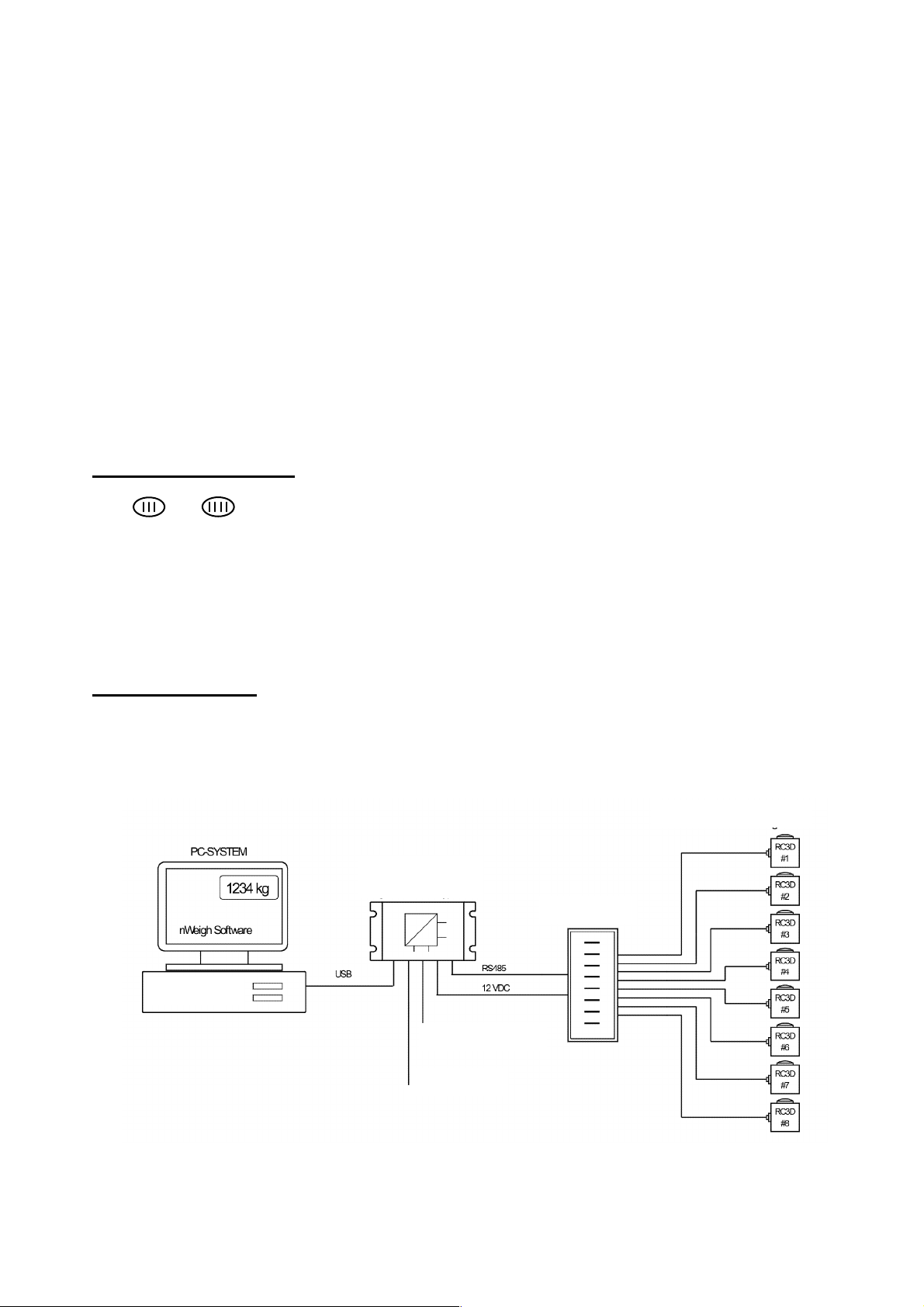
3. Introduction and Block Diagrams
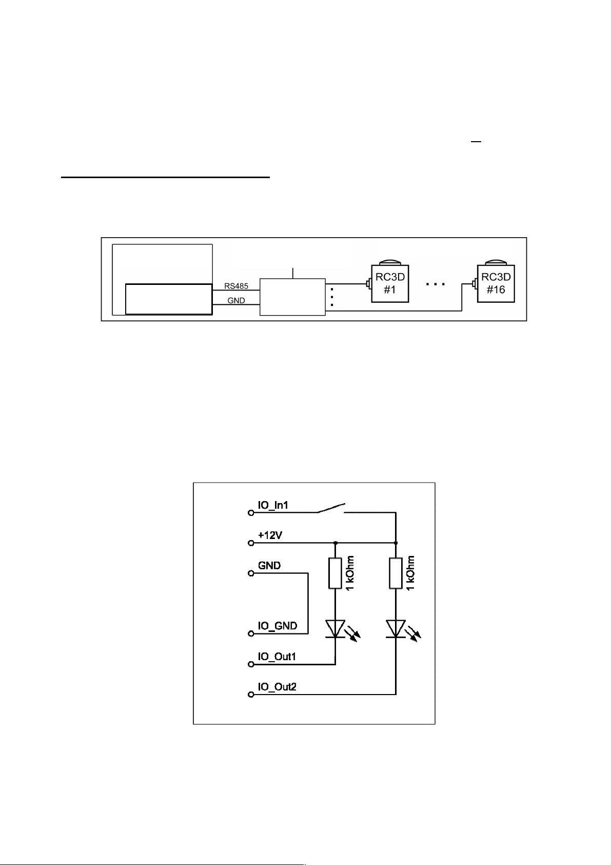
Fig. 3.1: Connection of RC3D digital load cells via KPFD
-
8 junctio
n box
Scale Interface
The W&M approved type FW-01 Scale Interface is the key component to integrate a Weighing System into your
PC. FlintWeigh does not require any separate weight display and the scale interface assures, that the weight
data will be reliably processed in the PC.
It is possible to connect up to 2 scales (up to 16x type RC3D digital load cells respective 2x type LDU digital
amplifiers) via RS485 to the scale interface, which will be connected to the PC via USB interface.
When the scales are based on standard load cells you can select among several LDU types which may be
plugged into socket within the KAL-4 junction box. The selection of the applied LDU will be defined by the
requirements for the weighing application. The technical characteristics of the LDU types and connection
details about digital and standard load cells you can find in chapter 4.
3.1. Application Range
For protecting the consumers all scales which are used for commercial transactions (legal for trade
applications) have to be calibrated in a standardized way. Typical legal for trade scales are retail scales in
shops. Privately used bathroom scales or kitchen scales are examples for scales which don’t require an
approved calibration.
Legal for trade applications
The weighing terminal has an EC type approval which covers standard load cells and scales of the accuracy
class and .
All load cells have to keep the tolerances according "OIML R60, Metrological regulation for load cells, Edition
2000".
For selecting the proper weighing module in legal for trade applications, it is required to verify the compatibility
of modules for the weighing instrument (see file KOMPMODENG.XLS on the Flintec CD-ROM).
For further information about software, alibi memory and legal for trade applications see chapter 4.
Industrial applications
All scale connections in industrial applications fall within the responsibility of the scale operator. In such
applications an approved alibi memory is not available.
3.2. Block Diagrams
Alibi memory
Digital Load Cells
Type FW-01
KPFD-8
12 V DC Supply
Digital I/O
FlintWeigh Technical Manual, Rev. 3.03 November 2011
Page 5 of 32
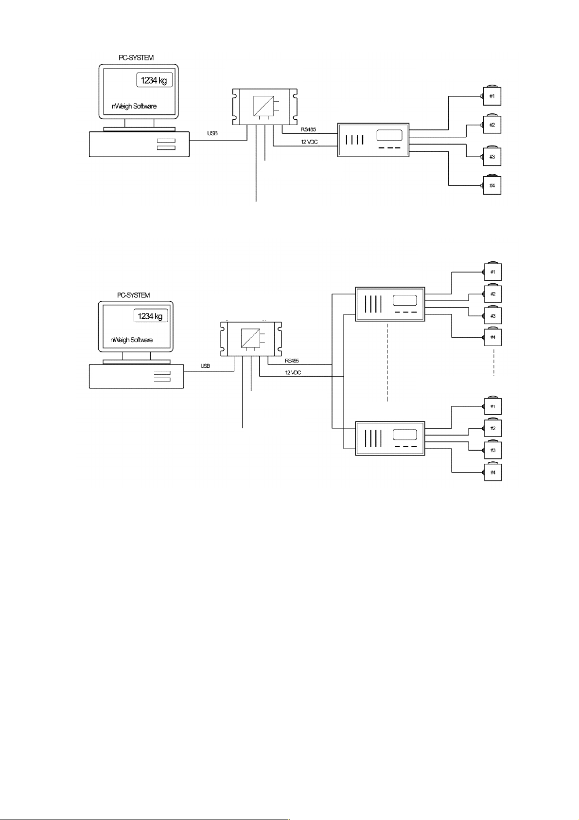
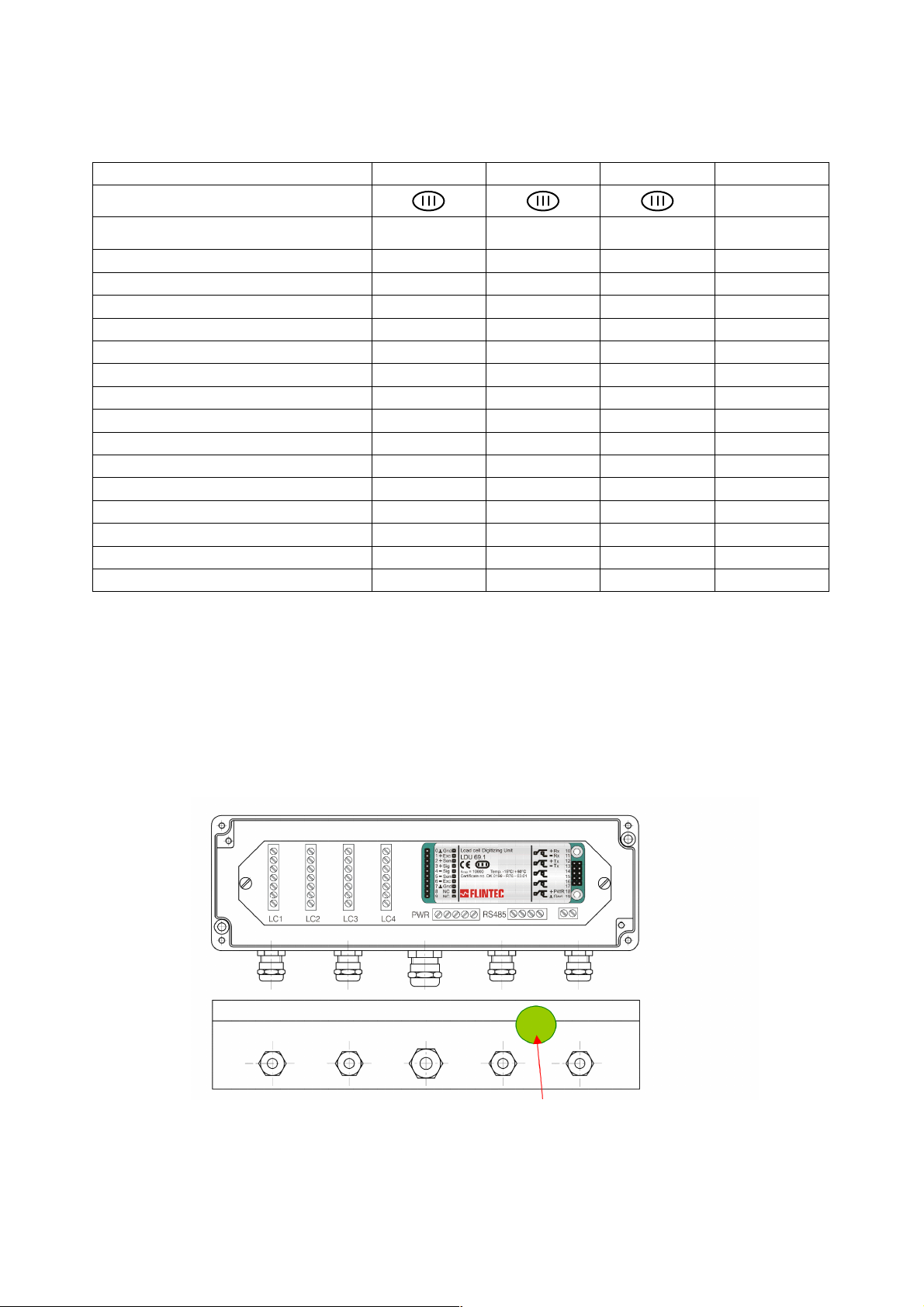
Fig. 3.2: Connection of standard load cells via KAL
-
4 junction box with integrated LDU
Fig. 3.3: Block diagram with standard load cells and 2 scales
Scale Interface
Scale Interface
Type FW-01
Standard Load Cells
KAL-4
Alibi memory
12 V DC Supply
Digital I/O
Standard Load Cells
KAL-4
Type FW-01
Alibi memory
Standard Load Cells
12 V DC Supply
KAL-4
Digital I/O
3.3. Scope of Delivery
► Type FW-01 Scale Interface
► Suitable plug connectors for the load cells and the digital I/O
► FlintWeigh II Software
► This manual
► A medium (CD-ROM) with the FlintWeigh II software, the technical manual, the test certificates of the
LDUs, the FlintWeigh II EC type approval, some examples for using the OLE functions and a template
for the scale’s descriptive plate in RTF format
3.4. Available Accessoires
► Type KPFD-8 junction box for type RC3D digital load cells
► Type LDU 68.1 / 68.2 / 69.1 / 78.1 digital amplifiers for standard load cells
► Type KAL-4 digital junction box
FlintWeigh Technical Manual, Rev. 3.03 November 2011
Page 6 of 32
4. System Components and Technical Characteristics
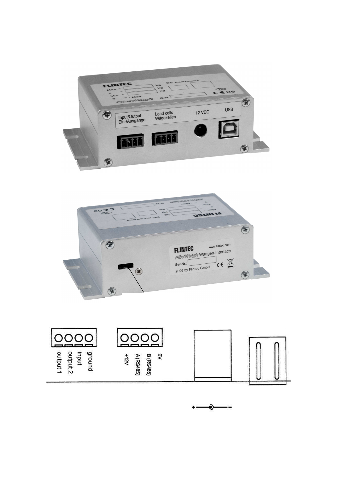
Fig.4.1 Scale interface, connector side
Fig.4.2 Scale Interface; calibration lock (will be sealed in legal for trade applications)
Fig.4.3 Scale Interface;
connectors
4.1. Type FW-01 Scale Interface
Calibration lock
Digital
Digital
Input/Output
Input/Output
-
Digital load cell connector suitable for connecting RC3D load cells or one/two units of LDU xx.x in
half-duplex mode, see LDU xx.x manual
-
External 12 V supply required for powering the digital load cells / LDU units
FlintWeigh Technical Manual, Rev. 3.03 November 2011
Digital
Digital
Load cells
Load cells
USBSupply 12 V DC
USBSupply 12 V DC
Page 7 of 32

4.2. Technical Specifications
GENERAL
Scale interface
ACCURACY
Accuracy Class III
EU Type approved
DISPLAY AND KEYBOARD
Display
Resolution Selectable up to 99 000 counts (in accordance with the regulations)
Status annunciators Net mode, No Motion, Max. and Min, e, Scale no.
Keyboard The standard PC keyboard is used
INTERFACE TO DIGITAL LOAD CELLS
Communication & Protocol
Excitation 12 V DC, max. 450 mA
No. of load cells / load cell
digitizing units
Load cell connection
SCALE CALIBRATION AND FUNCTIONS
No. of scales
Calibration Calibration performed by FlintWeigh II software
Corner correction Digital corner correction (only with type RC3D load cells)
Weighing functions Zero, tare, gross, motion detection, automatic zero tracking (Active-X-Control)
COMMUNICATION
To PC USB 2.0
DIGITAL INPUTS / OUTPUTS
Output 2x opto-isolated for setpoints (Open collector, 24 V DC, 50 mA)
Input 1x opto-isolated, 24 V DC
POWER
Power requirements
ENVIRONMENT AND ENCLOSURE
Operating temperature -10…+40 °C
Storage temperature -10…+70 °C
Humidity 40 to 90% RH (non-condensing)
EMC According to OIML R 76 and EN 45501 requirements
Enclosure Aluminium housing (IP 40), installed in the direct vincinity of the PC system
PC SYSTEM
Requirements
Intelligent interface with non-volatile memory for system parameters and
calibration data
10 000 intervals (single interval) or n x 3 000 intervals (multi range / multi
interval)
Approval no. D-10-09-024 from 09th August 2010
Approved PC-based weighing system with weight display on PC monitor
(Active-X-Control)
RS485 half-duplex, baud rate 9 600…38 400; E7,1 OR 8N,1; compatible with
type RC3D load cell respective type LDU xx.x load cell digitizing unit
Up to 10 pieces directly powered type RC3D digital load cells OR
up to 16 pieces externally powered type RC3D digital load cells OR
up to 2 pieces directly powered type LDU xx.x load cell digitizing units
(valid for one scale interface)
4-wire technique,
2 wires for the digitale interface and 2 wires for the sensor supply
Up to 2 scales per scale interface
With type RC3D it’s possible to have a 2-deck weighbridge system
12 V DC / max. 1.5 A; power consumption depends on number of connected
load cells / load cell digitizing units
Windows XP; 1024 x 768 or higher graphic resolution; 128 MB or more RAM,
512 MB or more harddisk memory, USB 2.0 Interface
FlintWeigh Technical Manual, Rev. 3.03 November 2011
Page 8 of 32
4.3. Important Information about the Operation of Digital Load Cells
Fig. 4.4: Schematic of the external power supply to the digital load cells
Fig. 4.5 : Wiring example for the digital I/O
Pin 6
Pin 2
Pin 1
Pin 5
Pin 7
Pin 8
box
+12V DC / 1.5 A
The connection of the digital load cells has to be done according the description in the KPFD-8 manual (see
Flintec-CD, technical documents, manuals).
It is allowed to connect up to 16 digital load cells (e.g. type RC3D) to the scale interface.
IMPORTANT: If you connect more than 10 digital load cells, then it is mandatory to power all load cells from an
external power supply.
External power supply for digital load cells
The external power supply has to provide a stabilized +12 V DC / ±5% with at least 1.5 A current. The input
goes directly to the connection cable of the digital load cells. Only the pins "RS485 A", "RS485 B" and "GND"
will be connected with the scale interface.
Weighing terminal
External power supply
Digital load cells
Weighing
system controller
Junction
4.4. Information about the Digital Inputs / Outputs
The digital I/O connections (one input, two outputs) can be used connecting e.g. a traffic light, a gate or a
switch-key.
Digital output: 2x, open collector (max. 24 V DC, max. 50 mA)
Digital input: 1x, opto-isolated, 3...24 V DC, max. 20 mA; min. switching current = 1,5 mA
FlintWeigh Technical Manual, Rev. 3.03 November 2011
Page 9 of 32
4.5. Operation of Standard Load Cells
Fig. 4.6: Sealing details with sticker
The scale interface can be connected with up to two LDU amplifiers. Depending on the application – legal for
trade scale or industrial application – it can be selected among various weighing modules.
Weighing module type LDU 68.1 LDU 69.1 LDU 78.1 LDU 68.2
Accuracy class
Certificate no.
Intervals "n" acc. Kompmodeng: n
ind
DK0199-R76-
10.04 Rev.1
DK0199-R76-
11.08 Rev.1
DK0199-R76-
10.08 Rev. 1
10.000 10.000 10.000
Internal resolution ± 130 000 > ± 1 000 000 ± 260 000 ± 130 000
Approved single range scale
Approved multi range scale no
Approved multi interval scale no
Load cell excitation U
Minimum input voltage U
Approved min. input per vsi ∆U
EXC
MIN
min
yes yes yes
yes yes
yes yes
5 V DC 5 V AC 5 V DC 5 V DC
0 V 0 V 0 V 0 V
1.0 µV 0.1 µV 0.3 µV
Input sensitivity 0.05 µV/d 0.02 µV/d 0.05 µV/d 0.1 µV/d
Min. load cell impedance R
Max. load cell impedance R
Min. operation temperature T
Max. operation temperature T
Fractional error limit P
ind
Load cell connection 4-/6- wire technique
Tab. 4.3: Technical characteristics of LDU amplifiers
Lmin
Lmax
min
max
87.5 Ω 87 Ω 87.5 Ω 87.5 Ω
1150 Ω 1200 Ω 1150 Ω 1150 Ω
-15 °C -15 °C -15 °C -15 °C
+55 °C +55 °C +55°C +55 °C
0.5 0.5 0.5
4/6 4/6 4/6 4/6
The connection of the standard load cells has to be done as described in the manual of the KAL-4 digital
junction box (see Flintec-CD, technical documents, manuals).
Not approved
no
no
no
4.6. Sealing Details with Sticker
The legal for trade operation requires a sealing of the junction boxes. The following figure shows a possible
positioning of the sticker for KAL-4
FlintWeigh Technical Manual, Rev. 3.03 November 2011
Page 10 of 32

4.7. Descriptive Plate
Fig. 4.7: Descriptive plate of the weighing terminal
The descriptive plate has to be placed on the weighing terminal’s enclosure. It must coincide with the digital
descriptive plate within the FlintWeigh II software.
The descriptive plate supplies following information:
► Owner and number of the EC type approval
► Version no. of the software incl. revision no./ check sum
► Serial no. of the built-in weighing system controller
► Type and serial no of the LDUs
► Year of manufacture
► Traceable access counter (TAC)
► Metrological symbol “M”
► Interval, min.load and max. load of the scale
Hint: You can find a template for the scale’s descriptive plate in RTF format on the Flintec CD-ROM.
FlintWeigh Technical Manual, Rev. 3.03 November 2011
Page 11 of 32

5. FlintWeigh II Software Installation
Fig. 5.1 : Software source directory on the Flintec CD
Fig. 5.2 : Software target directory on the installation PC
The FlintWeigh II software displays the continuously measured weight value of the weighing system controller
within a graphical window in a legal for trade quality.
FlintWeigh II also provides an OLE interface. External programmes can access the data and information within
FlintWeigh II by using OLE functions. All windows and control buttons are part of the OLE interface.
By configuring two digital outputs and one digital input it is possible to implement a simple limit monitoring or
traffic light control.
5.1. Software Version
The software version is defined as follows:
NWxyF.exe with x = Main version no.
and y = Revision no.
5.2. Installation
It is not required to install the FlintWeigh II software in the conventional way. Just copy from the Flintec-CD to a
directory of your choice on a target PC of your choice:
► The directory “USB Driver 2008“ (Windows 7 / Vista) respective “USB Driver 2006“ (Windows XP);
these driver files are required to install the scale interface via USB connection
► the files "NW11F.exe" and " nxWeigh.dll"
e.g.: NW11F.exe Main version no. 1, Rev. no. 1
Hint: Your profile as a Windows user requires writing preferences for this installation directory. In this directory
further configuration files will be created (see chapter 5.3).
Then you connect the scale interface to an USB port of the installation PC. Hereby the installation PC
automatically detects the scale interface and the operating system will search for a suitable device driver, which
you can find in the directory “USB Driver 2008“ (Windows 7 / Vista) resp. “USB Driver 2006“ (Windows XP).
After the successful driver installation the Windows device manager should list the FlintWeigh scale interface in
the section “Connections (COM & LPT)“ listen. Please note the assigned COM port no. for further use during
the commissioning.
When started for the first time FlintWeigh II should start with the language setting "English" (see chapter 8.2).
FlintWeigh Technical Manual, Rev. 3.03 November 2011
Page 12 of 32

5.3. FlintWeigh II Files
In the FlintWeigh II software directory you can find the following files (some files may be hidden or protected
and therefore not visible):
NW11F.EXE
NW10.KEY
NW10.INI
NW10.LIM
NW10xx.CFG
Following files may be located in the FlintWeigh II software directory or somewhere else (see data memory
Server):
NW10.CNT
FlintWeigh II main programme; can be used directly (EXE file) as weight display or for
service and calibration purposes. In weighing mode the main programme can communicate
to application programmes via its integrated OLE interface. If the OLE interface is in use the
FlintWeigh II software automatically starts in the weighing mode.
This file will be created during the commissioning. It contains non-approved parameters and
settings like COM port, baud rate, remote display, language, filter settings, zero tracking,
etc.
This file will be created during the commissioning. It contains the path information to the
storage location of the alibi data.
This file will be created during the commissioning. It contains the manual settings of the
digital outputs (setpoints).
This file will be created during the commissioning. For diagnosis purposes it contains copies
of the calibration data, which are stored in the approved memory of the weighing system
controller.
Record counter (for multi scale systems), protected by CRC16 checksum
NWmmjj.MEM
Alibi memory files, divided by month (mm = month, yy = year), protected by CRC16
checksum
FlintWeigh Technical Manual, Rev. 3.03 November 2011
Page 13 of 32

6. Weight Display and Control Buttons
Fig. 7.1 : Weight display and control but
tons
Service functions: the win
dow
FlintWeigh II
opens (6)
Displayed scale (no.) and select scale (7)
Zeroing the selected scale (8)
Taring the selected scale (9)
Operation mode of the selected scale (10)
(1) Display window FlintWeigh II
(2) Logo
(3) Software version and checksum
(4) Weight value
(5) Weight unit*
(6) Service functions
(7) Displayed scale (no.) and select scale
(8) Zeroing the selected scale
(9) Taring the selected scale
(10) Operation mode of the selected scale
(11) “Print” (record) to alibi memory
(12) Alibi memory
*Unit in black letters: scale is calibrated
Unit in grey letters: scale has no valid calibration
The various functions will be described below.
In the weighing mode via the OLE interface only the window “Information“ will be opened.
It’s not possible to set up anything.
Currently scale no. 1 is displayed.
Other options are:
Scale no. 2 is displayed
Dual scale function, sum of scale no. 1 and no. 2
Zeroing is only allowed for the empty scale. The current load must fall within the defined
zeroing range ( -1% to +2% off max. load in legal for trade applications; user-defined range
in industrial applications)
Taring is only allowed, if the current gros weight is positive and the scale is in no-motion
condition. When clicking this button the scale will be tared (gros net). The next click on
this button will delete the tare weight (net gros).
A tared scale will display the additional info “NET“.
The next click on this button will delete the tare weight (net gros).
Scale is stable (no-motion condition)
Scale is within the zero setting range
Active weighing range (1, 2 or 3)
“Print” (record) to alibi memory (11)
Performs a weighing and saves the corresponding data to the alibi memory
Alibi memory (12)
Here you can view and print the contents of the alibi memory
FlintWeigh Technical Manual, Rev. 3.03 November 2011
Page 14 of 32

7. FlintWeigh II Configuration
Fig. 8.1 Weight dis
play before commissioning
Fig.8.2 Register „Communication“
Sensor interface:
Sensor type:
Scale system:
Data memory:
Remote display:
Gravitational factor:
7.1. Basic Setup during the Commissioning
When you commission FlintWeigh II for the first time, following basic setup has to be done:
• Sensor interface and Sensor type ( standard load cells OR digital load cells)
• Scale system
• Data memory
• Interface to remote display and remote display type
• Gravitational factor, if applicable
These basic settings will be described in this chapter.
Start the main programme ”NW11F.EXE“
A click on this button will open the service functions
(window FlintWeigh II Settings).
Select the serial interface, which has been assigned to the weighing system
controller (see chapter 5.3) and set up the baud rate to „9600“
Defines, if standar or digital load cells will be connected
(LDU = standard load cells; RC3D,= digital load cells)
Defines, if there will be “1 scale“, “2 scales“ (independend from each other) or a
“Dual scale”
(Dual scale = sum of scale no.1 and scale no.2)
Location for the alibi memory (see chapter 8.1.1)
Define interface and type as required
Is only used, if the calibration location and the installation location are not
identical. Otherwise this parameter remains untouched.
Default setting: 9.8075656
FlintWeigh Technical Manual, Rev. 3.03 November 2011
Page 15 of 32

7.1.1. Configure the Alibi Memory
Fig.8.3 Configure the alibi memory
Fig.8.4 Alibi memory in a local dir
ectory
Fig.8.5 Alibi memory on a network drive
In legal for trade applications the recorded weighing results will be stored to an approved data memory, the so
called alibi memory.
In the standard installation the data memory will be
automatically created in the FlintWeigh II
programme directory.
Generally the location for the data memory can be
selected freely, e.g. it is allowed to choose another
local directory or any network drive.
For changing the memory location click on the
folder sign in the Data memory area.
FlintWeigh Technical Manual, Rev. 3.03 November 2011
Page 16 of 32

7.2. Language and other Settings
Fig. 8.6 Register „Parameters“
Filter characteristics:
Language:
Zero tracking:
Zero after power on:
Frameless:
Record lock:
Input (tilt)
Zero crossing
Changing > 20e
Passcode:
Output 1:
FlintWeigh II has some setup parameters, which can be set up before or after the commissioning. If you have
configured a multi scale system, then first select the wished scale (“1” or “2”) in the weight display (Fig. 7.1).
Selected scale
Filter characteristics for the digital signal processing: Depending on the application the
settling characteristics can be set to “fast“ (shortest settling time), „medium“ (factory
setting) or „slow“ (best averaging)
(the record lock is
active, if the weight unit
shows a grey
background)
Select as necessary, the selected language will be activated immediately
Enables / disables the automatic zero tracking in normal weighing mode
(automatic zeroing of the display, if the scale is stable and the current weight value
falls within the zero setting range)
Enables / disables the automatic zeroing after software start
(automatic zeroing of the display, if the scale is stable and the current weight value
falls within the zero setting rang)
Enables / disables the frameless operation of the software
If "Frameless" is enabled, the window will be displayed without title bar and frame in
the operation via OLE communication.
Enables the digital input as a recording criteria, e.g. tilt sensor
(closed = recording allowed; open = recording locked)
If enabled, the scale must be unloaded before a new weighing
result can be recorded
If enabled, the displayed weight has to change by at least 20 e
before a new weighing result can be recorded
Here you can define an alphanumeric user-defined password (1 to 8 characters) for
protecting the FlintWeigh II settings from any unauthorized access.
If this field is empty, no password will be asked.
Attention: Please note your password! If a password is defined you will never get
access to the scale settings without this password.
Output 2:
FlintWeigh Technical Manual, Rev. 3.03 November 2011
The functionality of the digital outputs, e.g. setpoint outputs, normally will be defined
after the scale calibration (see chapter 8.7).
Page 17 of 32

7.3. Scale with Standard Load Cells
Fig. 8.7 Register ”Calibration“
Sensor address:
LDU
-
Typ Sensor address
Comment
Scale type:
Setting
Comment
Scale interval 1/2/3:
Decimals:
Unit:
No-motion range /
Max. capacity:
Important: The sensor type already has been set to “LDU” (see Fig. 8.2; Register “Communication“).
If you have to configure a multi scale system, then select the wished scale no. ("1" or "2") within the weight
display (Fig. 7.1).
7.3.1. Define the Scale Parameters
For sensor type “LDU“ and
single-interval scale
Selected scale
Defines the address for the LDU (see table below for the factory settings) and enables
the LDU (by activating the check box besides the input field)
Note: The address in parentheses will be used for the second LDU, if two LDUs of the
same type will be used.
68.1 1 (2) Legal for trade
69.1 3 (4) Legal for trade
78.1 5 (6) Legal for trade (see chapter 4.4)
68.2 7 (8) Not approved
Single-interval The scale has exactly one weighing range with a constant scale
interval
Multi-range The scale has 2 or 3 weighing ranges with different scale intervals. If
the current gros value of the measured weight falls within the next
weighing range and larger scale interval (changeover threshold 1 and
2), then the larger scale interval remains active until the scale will be
unloaded and will return to the zero point.
Multi-interval The scale has 2 or 3 weighing ranges with different scale intervals.
The current gros value of the measured weight determines the active
weighing range and the active scale interval at any time.
Step size of the display resolution for the scale respective the weighing range
period:
FlintWeigh Technical Manual, Rev. 3.03 November 2011
Number of digits after the decimal point
Weight unit for the displayed weight: g, kg, t or lb
Condition for a stable scale (no. of scale intervals, no. of measured values);
Default: 2d and 10 values in legal for trade applications; in industrial applications these
criteria may be modified
Maximum load of the scale (as a multiple of the scale interval e1)
Page 18 of 32

Min. capacity:
Minimum load of the scale (as a multiple of the scale interval e1)
Test weight:
Changeover
Fig. 8.8 Addressing load cells in a weighbridge / vehicle scale
Fig.8.9 Register ”Calibration“
Fig.8.10 RC3D Load cells
Sensor
-
Adresse:
Weight of the calibration weight (as a multiple of the scale interval e1)
Only for multi-range / multi-interval scales:
threshold 1/2:
Transition points for range or interval (as a multiple of the scale interval e1)
Important: For saving all scale parameter settings you have to close the window FlintWeigh II Settings
afterwards.
Now the weight display (Fig. 7.1) should show a random value.
The next step is the calibration of the scale (see chapter 8.5).
7.4. Scale with Type RC3D Digital Load Cells
Important: The sensor type already has been set to “RC3D” (see Fig. 8.2; Register “Communication“).
If you have to configure a multi scale system, then select the wished scale no. ("1" or "2") within the weight
display (Fig. 7.1).
7.4.1. Preliminary Note
The next figure shows the basic principles of addressing the load cells in a weighbridge / vehicle scale. The
shown numbering simplifies the corner correction (chapter 8.4.3).
7.4.2. Define the Scale Parameters
for sensor type “RC3D“ and Single-interval scale
After activating the check box “enable” and clicking the button “RC3D“ the window
“RC3D Load Cells“ will be opened (see Fig. 8.10).
Here you select the load cells by their addresses (A, B, C, etc.). The serial numbers will
be read and displayed automatically.
If one or more address fields should have a red background, then the communication to
this/these load cell(s) is not OK. The corresponding load cells have to be checked
(address, protocoll, load etc.)
FlintWeigh Technical Manual, Rev. 3.03 November 2011
Page 19 of 32

Scale type:
Setting
Comment
Scale interval 1/2/3:
Decimals:
Unit:
No-motion range /
period:
Max. capacity:
Min. capacity:
Test weight:
Changeover
Fig.8.11 RC3D Load cells
Single-interval The scale has exactly one weighing range with a constant
scale interval
Multi-range The scale has 2 or 3 weighing ranges with different scale
intervals. If the current gros value of the measured weight falls
within the next weighing range and larger scale interval
(changeover threshold 1 and 2), then the larger scale interval
remains active until the scale will be unloaded and will return to
the zero point.
Multi-interval The scale has 2 or 3 weighing ranges with different scale
intervals. The current gros value of the measured weight
determines the active weighing range and the active scale
interval at any time.
Step size of the display resolution for the scale respective the weighing range
Number of digits after the decimal point
Weight unit for the displayed weight: g, kg, t or lb
Condition for a stable scale (no. of scale intervals, no. of measured values);
Default: 2d and 10 values in legal for trade applications; in industrial applications these
criteria may be modified
Maximum load of the scale (as a multiple of the scale interval e1)
Minimum load of the scale (as a multiple of the scale interval e1)
Weight of the calibration weight (as a multiple of the scale interval e1)
Only for multi-range / multi-interval scales:
threshold 1/2:
Transition points for range or interval (as a multiple of the scale interval e1)
Important: For saving all scale parameter settings you have to close the window FlintWeigh II Settings
afterwards.
Now the weight display (Fig. 7.1) should show a random value.
The next step is the digital corner correction (see chapter 8.4.3).
7.4.3. Digital Corner Correction
Important: After the digital corner correction the scale always requires a new calibration.
Each corner (load cell) will be loaded one after the other with a
calibration weight (the calibration weight should be at least 10%
of max. capacity; better is 30% of max.capacity).
Using the slider the display value of the loaded load cell will be
corrected until the displayed value equals the calibration
weight.
The corner correction doesn’t depend on the sequence of the
loaded load cell, but a systematic course may spare time and
minimises the risk for errors (see chapter 8.4.1).
Hint: It may be meaningful to perform a calibration of the scale
and save the calibration data before the corner correction. This
optimises the display characteristics already before the corner
correction.
The next step is always the calibration of the scale (see chapter 8.5)
FlintWeigh Technical Manual, Rev. 3.03 November 2011
Page 20 of 32

7.5. Calibrate the Scale
Important: Before you can calibrate the scale you have to define the basic setup (see chapter 8.1) and the
scale parameters (see chapter 8.3 respective 8.4). If you have to configure a multi scale system, then select the
wished scale no. ("1" or "2") within the weight display (Fig. 7.1).
1. Open the window “nWweigh Settings“
2. Open the register “Calibration”
3. Unload the scale
4. Click the button “Dead load“; this defines the
current load status of the scale as the zero
point. The weight display should show now the
value “0”.
5. The calibration weight will be put on the centre
of the scale. The true applied weight (at least
10% of max. capacity) has to be entered into
the field “Test weight” (here 2500e = 5 kg).
6. Click the button “Gain“; now the correct gain
for the selected scale will be calculated. The
weight display should show now the value of
the calibration weight.
7. For saving the calibration data click the button
“Save calibration data”. Now a warning
appears which describes the consequences in
legal for trade applications. (“Attention! After
saving the claibration data, the internal
calibration counter (TAC) is still counted
forward. Afterwards the scale has to be reapproved by the Calibration Authority!”)
8. For confirming the saving click the button
“Save”. If you want to keep an existing
approval click the button “Cancel”.
9. After the calibration the window FlintWeigh II
Settings has to be closed. This will save all
setup changes.
10. The weight display will now show the weight of
the calibration weight, if the calibration weight
still loads the scale.
Hint: After the calibration you have to close the window FlintWeigh II Settings by clicking the button “X“ (upper
right window corner). In multi scale applications you may select and calibrate the second scale now.
FlintWeigh Technical Manual, Rev. 3.03 November 2011
Page 21 of 32

7.6. Optional Linearisation of the Scale Curve
The standard scale calibration may be supplemented by a linearisation with up to 5 correction points. Hereby
the correction points have to be in a stricly increasing order, which is:
Min. capacity < Point 1 < Point 2 < Point 3< Point 4 < Point 5 < Max. capacity of the scale
Important: Before any linearisation you have to define the basic setup (see chapter 8.1), the scale parameters
(see chapter 8.3 respective 8.4) and you have to calibrate the scale (see chapter 8.5). If you have to configure
a multi scale system, then select the wished scale no. ("1" or "2") within the weight display (Fig. 7.1).
1. Open the window “nWweigh Settings“
2. Open the register “Linearisation“
3. Correction point 1: A calibration weight will be
put on the centre of the scale. The true applied
weight as a multiple of the scale interval e has
to be entered. Then you use the slider to correct
the display value until it equals the calibration
weight
4. Define correction point 2, if applicable (this is
done like correction point 1 but uses a higher
weight)
5. Define further correction points, if applicable
6. 7. For saving the calibration data click the
button “Save calibration data”. Now a warning
appears which describes the consequences in
legal for trade applications. (“Attention! After
saving the claibration data, the internal
calibration counter (TAC) is still counted
forward. Afterwards the scale has to be reapproved by the Calibration Authority!”)
7. For confirming the saving click the button
“Save”.
.
Hint: After the linearisation you have to close the window FlintWeigh II Settings by clicking the button “X“ (upper
right window corner). In multi scale applications you may select and correct the second scale now.
FlintWeigh Technical Manual, Rev. 3.03 November 2011
Page 22 of 32

7.7. Optional Use of Digital Outputs
Fig.8.11 Re
gister “Parameters“
Setting
Function
Fig.8.12 Example for the limit monitoring
After opening the service functions (window FlintWeigh II Settings) and selecting the register “Parameters“, you
can assign a functionality to the digital outputs:
for defining the digital outputs
Step 1: Select the source to control the output
Allowed settings are Scale 1, Scale 2 and
Combination.
Step 2: Assign a functionality to the output
Allowed settings are:
7.7.1. Setpoints and Limit Monitoring
“Off“ Without
“Limit“ Limit monitoring (see chapter 8.7.1)
“Traffic light“ Traffic light control (see chapter
8.7.2)
1. Select the scale as the source
2. Select the function “Limit“
3. Define the weight value as a multiple of interval
e; if the output shall follow the “Net value”, then
activate the associated check box
4. The output will be switched, if the “weight value
< Limit“. If the output shall show an inverse
logic, then activate the associated check box
“Exceeded”
5. By activating the check box “Input” you may use
the digital input as an additional switching
criteria for the limit monitoring: the setpoint
output will only be activated, if the digital input is
active, too
FlintWeigh Technical Manual, Rev. 3.03 November 2011
Page 23 of 32

7.7.2. Traffic Light Control
The implementation of a traffic light control requires following setup:
1. Define the function “Limit“ for digital output 1
2. Define the function “Traffic Light” for digital output 2
3. The setpoint values for both outputs have to be defined to the same value in such a way, that the
system can reliably detect an “Empty scale”
A functional setup switches the outputs as follows (vehicle scale example):
Action/Status
Output 1
(“Empty”)
Entrance Exit
Empty scale A1 = 1 Green Red
Vehicle is on the scale A1 = 0 Red
Red
Weight recorded A1 = 0 Red Green A2 = 1
Empty scale A1 = 1 Green Red
Output 2
(Weighing finalised)
A2 = 0
A2 = 0
A2 = 0
FlintWeigh Technical Manual, Rev. 3.03 November 2011
Page 24 of 32

8. Legal for Trade Operation
Fig. 9.1 Digital descriptive plate
Fig. 9.2 Successful recording of weight values
Fig. 9.3 Prevented recording of weight values
8.1. EC Type-approval and Test Certificate
See documents on the Flintec CD.
8.2. Digital Descriptive Plate
The digital descriptive plate will be displayed after opening the service functions (window FlintWeigh II Settings)
and selecting the register „Information“:
The digital descriptive plate must conform to the physical
descriptive plate.
(1) Version and revision of the software, checksum in
legal for trade applications in parentheses
(2) Hint area in non-approved applications
(3) Metrological symbol "M": green = approved, red = not
approved
(4) No. of EC type-approval
(5) Electronic calibration counter "TAC"
(6) Logo and address of the owner of the EC typeapproval
(7) Parameters of the selected scale
(8) Parameters of the weighing system controller and the
LDUs
Here you can also enable the 10-times higher resolution
display mode.
8.3. Recording of Weight Values in the Alibi Memory
Click the button within the weight display
The window „Information“ will be opened:
Here the record no. and the weight value to record will be
displayed.
For transfering them into the alibi memory click the “OK“ button.
If the error message „Recording is not possible“ appears, then
the scale was in motion or any of the enabled record locks (see
register „Parameters“) has prevented the successful recording.
FlintWeigh Technical Manual, Rev. 3.03 November 2011
Page 25 of 32

8.4. Show Alibi Memory
Fig. 9.4 Show alibi memory
Figure 9.5 Main window of the alibi memory
Fig. 9.6 Show logbook
Fig. 9.7 Main window of the Logbook
Click the button within the weight display
The window FlintWeigh II long-time memory will be
opened.
First select the month and year of the time period to
display
If necessary it is also possible to display archived
alibi data: search for the path to the file
(“NWxxxx.MEM”*) and afterwards click the button
“Show long-time memory”.
Contents of the long-time memory: COM port no.,
scale no., record no., date and time, weight, scale
status and tare weight where applicable.
If you click the button “Print” the contents of the
long-time memory will be printed.
*incl. path and file name e.g.
C:\FlintWeigh_II\NW0510.MEM
8.5. Logbook
Open service functions
Select register “Logbook”
Here you can view all changes which are relevant
for the legal for trade operation (e.g. calibrations,
updated software version, etc.).
Hint:
The amount of logbook entries is limited to 200.
FlintWeigh Technical Manual, Rev. 3.03 November 2011
Page 26 of 32

8.6. Obligations with Legal for Trade Scales
Structure
of the general scale data
Structure of the individual scales (3x for Scale 1, Scale 2 and Dual scale)
Logbook
The operator is responsible for the first and all regularly recurrent official calibrations.
Important: The official seal may only be broken by authorized qualified staff.
If one or more of the following changes has happened, the operater has to send a written note to the assigned
public authority and a new official calibration is mandatory:
► Broken seals
► Replaced load cells
► Replaced load carrier
► Replaced wiring
► Replaced LDUs
► Replaced weighing system controller
► Replaced descriptive plate
► Calibration of the scale
► Changes to the approved software settings
Hint: The user is responsible for the correct performance of any official calibration.
8.7. Legal for Trade Data within the Scale Interface
In legal for trade and industrial applications all calibration data will be stored in a flash memory in the scale
interface. These data can only be accessed, if the authentification of the FlintWeigh II Software to the scale
interface is valid. If these data will be saved during a calibration, the electronic calibration counter (TAC) will
automatically increased by one. The stored data is the following:
Serial no. Up to 17x per controller; up to 16x type RC3D digital load cell respective LDU
Gravitational factor Default value: 9.8075656
Calibration counter
Programme version x._
Programme revision _.x
Corner correction Max. 16 data records for up to 16x type RC3D digital load cell
Checksum EXE CRC16 for complete programme code
Checksum CRC16 for general scale data
Scale interval 3x for up to three ranges
Decimals
Unit
Min. capacity Default value: 20e
No-motion
Calibration weight
Max. capacity Max. capacity + 9e = overload
Changeover threshold 2x per scale (up to 3 ranges per scale)
Curve linearisation Up to 5 points per scale
Zero point (Dead load pt.)
Gain value
Scale type Single-interval, Multi-range, Multi-interval
Checksum CRC16 for scale data
Logbook entries Up to 200; 8 bytes incl. CRC for each
FlintWeigh Technical Manual, Rev. 3.03 November 2011
Page 27 of 32

9. Error Messages
Warnings
Software
Calibration
Important note: If a warning appears, the calibration data have to be saved again. Thereby the internal
calibration counter will be incremented by one which is especially relevant in legal for trade applications.
A new software version is used.
Elements of the calibration data have been changed.
FlintWeigh Technical Manual, Rev. 3.03 November 2011
Page 28 of 32

10. OLE Programming Interface
Function
Description
The programming interface to an application programme is executed as an automation (OLE-) server for 32-bit
Windows programmes (OLE = Object Linking and Embedding).
The communication between any application programme and FlintWeigh II will be done exclusively by the
following functions which are described below.
10.1. OLE Functions
Position (x,y) Position the weight display on the desktop ("0,0" belongs to top left corner)
Parameter Type Use
x Integer Horizontal position
y Integer Vertical position
Attention: It is mandatory to call this function exactly once during the initialisation of the
application software!
Stop() Stops communication
Attention: It is recommended to call this function once just before closing the application
software. This will stop the communication to the weight system controller clearly!
Switch(w) Select scale (only for multi scale systems)
Parameter Type Use
w Integer w = 1 (scale 1); w = 2 (scale 2)
w = 3 (dual scale)
Zero() Zeroing the selected scale
SetTare() Taring the selected scale
ClrTare() Delete the tare weight of the selected scale
PreTare(v) Set the tare weight for the selected scale manually
Parameter Type Use
v 32-bit
Integer
Tare value including all decimal places but without
decimal point ( e.g. 13.25 kg v = 1325)
Value Read the current weight value
Return value Format
String, 9 digits „nnnnnnndd“ with
nnnnnnn = weight value including decimal point, 7 digits
dd = weight unit, 2 digits
Hint: Unused places within the weight value will be filled with spaces.
Ten(t) Weight display with 10-times increased resolution (zoom)
Parameter Type Use
t Integer zoom off (t = 0) / zoom on (t= 1)
FlintWeigh Technical Manual, Rev. 3.03 November 2011
Page 29 of 32

Function
Description
Regist Register the current weight value – Format 1
Return value Value range
Format: string, 16 digits:
“rrrrrr nnnnnnn dd w” with
rrrrrr Record no., 6 digits 000001, 000002, 000003...
nnnnnnn
Weight value including
decimal point, 7 digits
0...800 000
dd Weight unit, 2 digits g, kg, t, lb
w Scale no., 1 digit 1 (scale 1); 2 (scale 2); 3 (dual scale)
Hint: Unused places within the weight value will be filled with spaces.
Attention: In legal for trade operation an entry to the alibi memory will be created and the
record counter will be incremented by one.
If a recording is not possible, a 2-digit error code will be notified:
E1 Scale in motion E4 No zero crossing
E2 Weight value ≤ 0 E5 Open input (tilt)
E3 Gros weight < minimum load E6 Overload, etc.
Regist2 Register the current weight value – Format 2
Return value Value range
Format: string, 30 digits:
“w_rrrrrr_nnnnnnn_kk_ttttttt_dd“ with
w Scale no., 1 digit 1 (scale 1); 2 (scale 2); 3 (dual scale)
rrrrrr Record no., 6 digits 000001, 000002, 000003...
nnnnnnn
kk Tare indication
ttttttt
Weight value including
decimal point, 7 digits
Tare value including
decimal point, 7 digits
0...800 000
„ “ (no tare); „ T“ (normal tare);
„PT“ (manual tare entry)
0...800 000
dd Weight unit, 2 digits g, kg, t, lb
Hint: Unused places within the weight value will be filled with spaces.
Attention: In legal for trade operation an entry to the alibi memory will be created and the
record counter will be incremented by one.
If a recording is not possible, a 2-digit error code will be notified:
E1 Scale in motion E4 No zero crossing
E2 Weight value ≤ 0 E5 Open input (tilt)
E3 Gros weight < minimum load E6 Overload, etc.
Param(w) Read scale parameters
Parameter Type Use
w Integer w = 1 (scale 1); w = 2 (scale 2); w = 3 (dual scale)
Return value Value range
Format: string, 17 digits:
"w_t_z1_z2_z3_k_dd" with
w Scale no., 1 digit 1 (scale 1); 2 (scale 2); 3 (dual scale)
t Scale type, 1 digit 1 (single-interval), 2 (multi-range), 3 (multi-interval)
z1 Scale interval 1, 2 digits 01, 02, 05, 10, 20, 50
z2 Scale interval 2, 2 digits 02, 05, 10, 20, 50 (at single-interval: 01)
Z3 Scale interval 3, 2 digits 05, 10, 20, 50 (at single-interval: 01)
k Decimal places, 1 digit 1, 2, 3, 4, 5
dd Weight unit, 2 digits g, kg, t, lb
FlintWeigh Technical Manual, Rev. 3.03 November 2011
Page 30 of 32

Function
Description
Status(w) Read scale status
Parameter Type Use
w Integer w = 1 (scale 1); w = 2 (scale 2); w = 3 (dual scale)
Return value Value range
Format: string, 31 digits:
"AB_gggggggdd_tttttttdd_nnnnnndd" with
A Status bit 1
B Status bit 2
gggggggdd Gros value and unit 0...800 000 / g, kg, t, lb
tttttttdd Tare value and unit 0...800 000 / g, kg, t, lb
nnnnnnndd Net value and unit 0...800 000 / g, kg, t, lb
Hint: Unused places within the weight value will be filled with spaces.
SetOutput(o,w,f,v) Configure digital outputs and setpoints
Parameter Type Use
o 32-bit Integer o = 1 (output 1); o = 2 (output 2)
w 32-bit Integer w = 1 (scale 1); w = 2 (scale 2); w = 3 (dual scale)
f 32-bit Integer
Flag Operation
2
21
22 0 (= 0) Under-run
23 0 (= 0) Gros value
24 Status of fixed setting
25 Enabled by input
20 (= 1) = No motion
21 (= 2) = Active tare (net indication)
22 (= 4) = Zero setting range
23 (= 8) = Accurate zero
24 (= 16) = Error
20 (= 1) = Zero crossing
21 (= 2) = Minimum load
22 (= 4) = Tilt switch
00 Output not used
0
01 Fixed setting
02 Setpoint control
03 Traffic control
1 (= 1) Exceeded
1 (= 8) Net value
0 (= 0) Off
1 (= 16) On
0 (= 0) Off
1 (= 32) On
v 32-bit Integer Setpoint including all decimal places but without decimal
point ( e.g. 13.25 kg v = 1325)
All functions are characterised in the type library “NW10.TLB”, which may be included into the programming
environment of the application programme.
FlintWeigh Technical Manual, Rev. 3.03 November 2011
Page 31 of 32

10.2. Application Example
Example 1 – Visual Basic:
Call of OLE function "Regist" in VB
------------------------------------------------------ Dim scale As Object
'Create object and position the weight display
'(only once in the programme during initialisation)
Set scale = CreateObject("scale99.serv")
Call scale.Position(0,0)
'Recording
'(several times during normal operation)
print_str = scale.Regist
'Stop communication
'(only once in the programme before closing)
Call scale.Stop
-------------------------------------------------------
Example 2 - VisualBasicScript / Windows Scripting Host:
Call of OLE function "Regist2" in VBS
'-----------------------------------------------------------' Sample programme for use of OLE connection to FlintWeigh II
'----------------------------------------------------------- '## Create Shell-Object ##
Set ws = CreateObject("WScript.Shell")
'## Create OLE-Object for "FlintWeigh II" ##
Set scale = CreateObject("Scale99.Serv")
'## First neccesary command to "FlintWeigh II"=position(x,y) ##
scale.position 0,0
'## Info message and waiting till "FlintWeigh II" is ready ##
ws.popup "Wait for initialisation of OLE server" ,1
WScript.Sleep (10*1000)
'## Show FlintWeigh II window ***
scale.Show
'## Wait for scale is ready and do recording–format 2 ##
Do
regist2value = scale.regist2
Loop Until (left(regist2value,1)<>"E")
'## Show result of recording – format 2 ##
msgbox regist2value
'## Stop OLE-Server ##
scale.stop
'----- End of Sample programme -----
www.flintec.com
FlintWeigh Technical Manual, Rev. 3.03 November 2011
Page 32 of 32
 Loading...