

Page 1
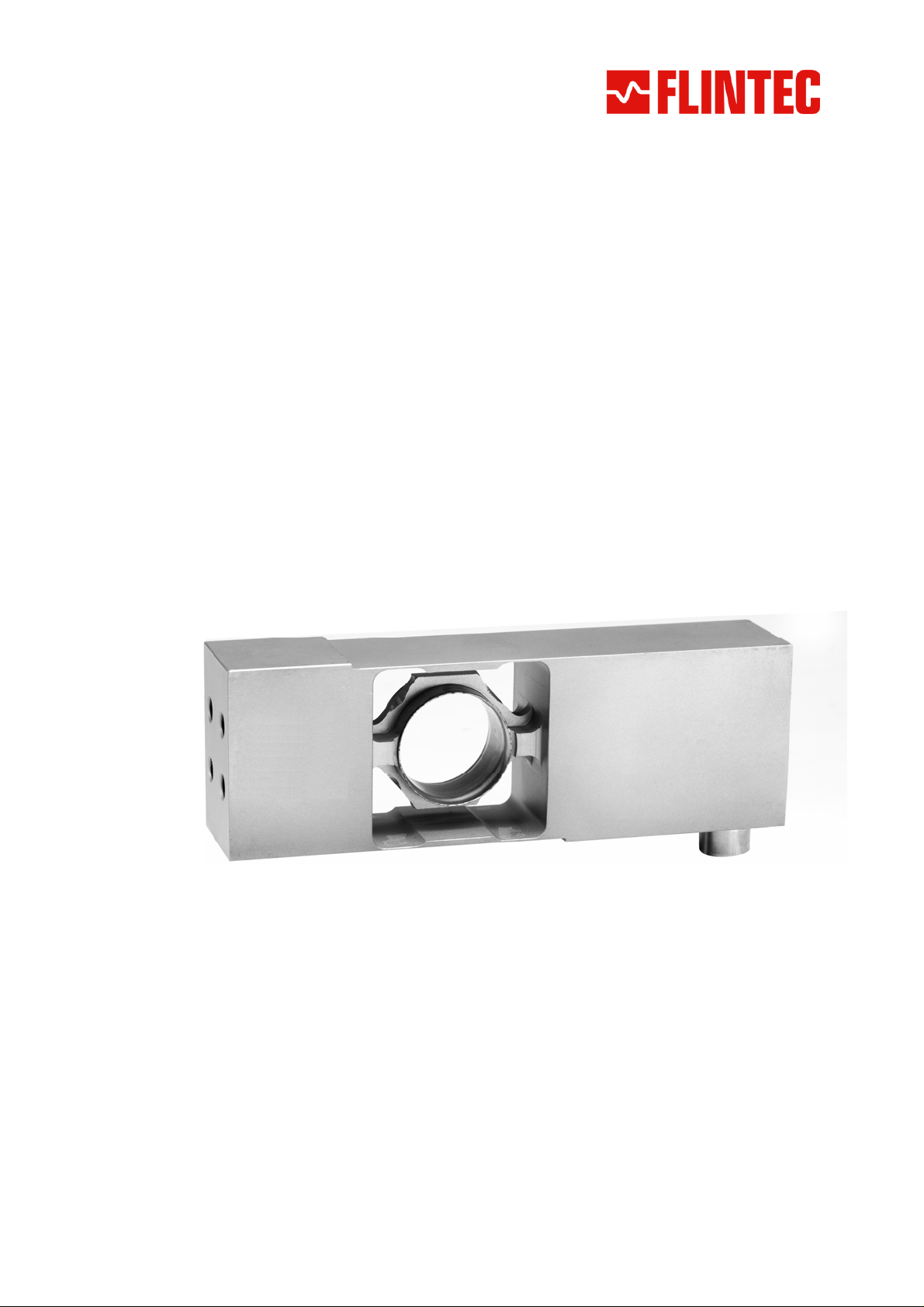
Type PC6D Digital Load Cell
Technical Manual
Document no. G142-Rev1.6-GB
Flintec GmbH
Bemannsbruch 9
74909 Meckesheim
GERMANY
Page 2
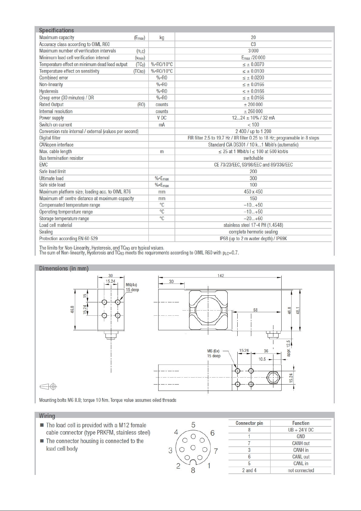
Page 2
Manual PC6D CANopen
Page 3

Contents
Part A: CANopen .................................................................................... pages 4 - 24
Part B: Commands ................................................................................. pages 25 - 45
ART A.................................................................................................................................5
P
1 INTRODUCTION............................................................................................................5
1.1 IDENTIFICATION AND SCOPE .....................................................................................5
1.2 PURPOSE.................................................................................................................5
1.3 ACRONYMS AND DEFINITIONS ...................................................................................5
1.3.1 Acronyms........................................................................................................5
2 SYSTEM DETAILED DESIGN.....................................................................................6
2.1 GENERAL.................................................................................................................6
2.2 CANOPEN................................................................................................................7
3 CANOPEN PROFILE...................................................................................................8
3.1 THE PDOS...............................................................................................................8
3.2 NETWORK MANAGEMENT ..........................................................................................9
3.3 COMMUNICATION PROFILE......................................................................................10
3.4 OBJECT DIRECTORY...............................................................................................10
3.5 QUICK START GUIDE..............................................................................................22
3.5.1 Process data objects ....................................................................................22
3.5.2 Service data objects .....................................................................................23
4 NOTES ........................................................................................................................24
4.1 FIRMWARE UPDATE (VIA CANOPEN).......................................................................24
4.2 FIRMWARE UPDATE (VIA PC)..................................................................................24
Manual PC6D CANopen Page
3
Page 4

PART B...............................................................................................................................25
5 COMMANDS................................................................................................................25
5.1 SYSTEM DIAGNOSIS COMMANDS – ID, IV, IS ..........................................................26
5.2 CALIBRATION COMMANDS – CE, CM, DS, DP, CZ, CG, ZT, FD, CS......................27
5.3 MOTION DETECTION COMMANDS – NR, NT.............................................................30
5.4 FILTER SETTING COMMANDS – FM, FL, UR ............................................................31
5.5 SET ZERO/TARE AND RESET ZERO/TARE COMMANDS – SZ, RZ, ST, RT.................33
5.6 OUTPUT COMMANDS – GG, GN, GT, GS ...............................................................35
5.7 SETPOINT COMMANDS - SN, HN, AN.......................................................................36
5.8 COMMUNICATION SETUP COMMANDS – AD, BR, TERMINAL RESISTOR.....................38
5.9 TRIGGER COMMANDS – SD, MT, GA, TE, TR, TL ..................................................39
5.10 TRIGGER SPECIAL COMMANDS– RW, TT, TS, DT, TW, TI, HT...............................42
5.11 SAVE CALIBRATION, SETUP & SETPOINT PARAMETERS COMMANDS – CS, WP, SS...45
Page Manual PC6D CANopen
4
Page 5

Part A
1 Introduction
1.1 Identification and Scope
This document describes the system design for a CANopen interface of the PC6D. It
describes the protocol used and the CAN open profile used to access the PC6D
1.2 Purpose
The purpose of this document is to specify the functionality, and performance of the PC6D
CANopen interface.
1.3 Acronyms and Definitions
1.3.1 Acronyms
This section includes a list of all abbreviations and acronyms used throughout the document
in alphabetical order.
CAN Controller Area Network
CANopen A higher layer protocol using the CAN.
Function A software entity that encapsulates some computations and can be used
without worrying about its implementation
NMT Network Management Protocol
PDO Process Data Object
Process A software entity that executes a computational entity, including modules
and functions.
RPDO Receive PDO
SDO Service Data Object
TPDO Transmit PDO
Manual PC6D CANopen Page
5
Page 6
2 System Detailed Design
2.1 General
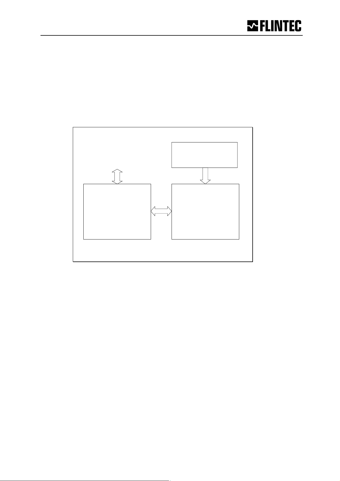
This software connects a physical load cell to a CANopen network. The PC6D digitizes, filters
and processes the analog inputs. It transports commands, responses and results from and to
the CANbus.
CANopen
Network
&
Power
Load Cell Sensor
Microcomputer
&
CAN interface
Analog Amplifiers
&
A/D converter
Figure 1- The PC6D Load-Cell
Page Manual PC6D CANopen
6
Page 7

2.2 CANopen
The PC6D follows the CAN2.0B recommendation. It receives both 11-bit identifiers, and
tolerates 29-bit identifiers. It only transmits 11-bit identifiers.
The PC6D is always quiet on the CANbus until the NMT Start command is received, except
for the very first ‘node guard’ message.
When started, the TPDO1 is used to send current status information. The TPDO1 holds the
module status and either net or gross weight, depending on the SDO selection. The default is
the Net value.
The TDPO2 is used for reporting ‘on-demand’ average measurements and reporting set-point
events.
The TDPO3 is used for reporting change in the Tare value.
In case of an overrun, error or failure an EMERGENCY message is sent to the CAN controller
indicating the nature of the error or failure.
EMERGENCY messages are transmitted when the CAN controller tries to set up a module
not present, or not functioning, when a module fails to answer the normal backplane scan and
when a module comes back online.
The RPDO1 can be used to set/reset Zero and Tare, and for quick selection of the Net weight
(default) or Gross weight as the data contained in TPDO1.
The RPDO2 can be used to send software triggers to start average measurements.
RPDO3 and RPDO4 are ignored by the PC6D.
SDOs are handled according to profile and CANopen recommendation.
The NMT protocol will use the ‘node guarding’ method.
The “SDO Block Download Protocol” may be implemented later.
Manual PC6D CANopen Page
7
Page 8

3 CANopen profile
3.1 The PDOs
The weight and status is sent constantly to the CANbus. The TPDO1 is sent 20 times per
second. The TPDO2 is sent every time the PC6D finishes a triggered measurement or a SetPoint is crossed. The TPDO3 is sent every time the Tare value is changed.
The format of the TPDO1, TPDO2 and TPDO3 is:
32 bit 16 Bit 8 bits 8 Bit
Weight Module Status Source Unused, zero
The first field is carrying weight information Gross or Net value if it is a TDPO1, Average
or Set-Point weight if it is a TPDO2.
Tare value if TPDO3.
Then module state follows as a 16 bit field width the following values:
$0001 - Under range
$0002 - Over range
$0004 - Not within Zero range (not yet implemented, zero)
$0008 - Exactly zero
$0010 - No motion, still stand, steady state
$0020 - Tare set
$0040 - Preset tare (0=tare is measured, 1=tare is set by user)
$0080 - Invalid weighing (wire-break, A/D ref. out of range)
$0100 - Set-point 1 (source>limit)
$0200 - Set-point 2
$0400 - Set-point 3
$0800 - Set-point 4
$1000 - Unused, zero
$2000 - Unused, zero
$4000 - Unused, zero
$8000 - Cold start
Source is zero in TPDO1 and TPDO3, and has the following meaning in TPDO2:
0 – (zero) Average result
1 – Setpoint 1 crossed
2 – Setpoint 2 crossed
3 – Setpoint 3 crossed
4 – Setpoint 4 crossed
Page Manual PC6D CANopen
8
Page 9
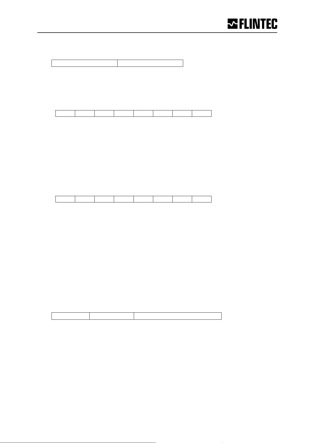
The format of the RPDO1 and RPDO2 is:
8 Bit 8 Bit
LDM select Command byte
Note: On PC6D the LDM selector byte is ignored.
The command byte of RPDO1 is used as follows:
Bit7 Bit6 Bit5 Bit4 Bit3 Bit2 Bit1 Bit0
Cmd: SnG SnN RZ SZ RT ST
Where
- SnG means select Gross Weight
- SnN means select Net Weight
- ST means Set Tare
- RT means Reset (Clear) Tare
- SZ means Set Zero
- RZ means Reset (Clear) Zero
The command byte of RPDO2 is used as follows:
Bit7 Bit6 Bit5 Bit4 Bit3 Bit2 Bit1 Bit0
Cmd: TR TS
Where
- TR is a software trigger that starts an average measurement.
- TS Trigger Stop; stop triggered measurement(s).
3.2 Network management
The PC6D implements the Network Management protocol with the node guarding protocol.
The PC6D also implements an address setup feature. The network controller may change a
PC6D node address using COB-ID = 0.
The frame must be sent while the PC6D is in its PRE-OPERATIONAL state and it must have
the following contents:
8 bits 8 Bit 48 bit (12 BCD digits)
Hex: 55 New CAN-ID BCD coded serial number
The serial number must be BCD coded and right-justified with as many leading zeros as
needed to make 12 BCD digits.
All PC6D on the CANbus will receive the message, but only the PC6D with the serial number
given will react to, and echo the frame with 55h changed to AAh. The PC6D will save the new
setting immediately and then restart itself.
Manual PC6D CANopen Page
9
Page 10
3.3 Communication Profile
The parameters which are critical for communication are determined in the communication
profile.
This includes the data for manufacturer's product nomenclature, for identification, or the
parameters for object mapping.
Abbreviations used in Tables:
ro
rw
wo
UI8
UI16
UI32
I32
REAL32
VS
read only
read / write
write only
(read will not be regarded as an error, but returns undefined results)
Unsigned8
Unsigned16
Unsigned32
Signed32
32 bit IEEE754 floating point
Visible String
3.4 Object Directory
The object directory of the CANbus communication module is described below:
Page Manual PC6D CANopen
10
Page 11
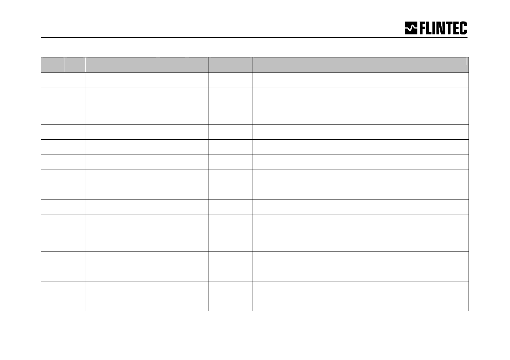
Communication Profile (Tables)
Index Sub-
index
1000 0 Device Type UI32 ro 00040191H Device Type
1001 0 Error Register UI8 ro 0 0: No error
1005 0 COB-ID Sync messg. UI32 rw 80H COB-ID of the SYNC object
1006 0 Communication cycle
100C 0 Guard Time UI16 rw 320 Cycle time in ms, set by the NMT Master or the configuration tool.
100D 0 Life Time Factor UI8 rw 3 Wait time is set by the NMT Master or the configuration tool.
100E 0 Node guarding
1014 0 COB-ID Emergency
1017 0 Heartbeat Time UI16 rw 0 Producer Heartbeat time. If index 1017h is nonzero Heartbeat is
1018 0
1
2
3
4
1400
1401 0
0
1
2
1
2
Name Type Attri-
bute
UI32 rw 50000 Minimum interval between TDPO1 (default 20Hz).
Period
UI32 rw 0x700 +
identifier
UI32 rw 80H +
Message
Identity Object
Vendor ID
Product Code
Revision Number
Serial Number
Number of elements
COB-ID
Transmission type
Number of elements
COB-ID
Transmission type
UI8
UI32
UI32
UI32
UI32
UI8
UI32
UI8
UI8
UI32
UI8
ro
ro
ro
ro
ro
ro
ro
ro
ro
ro
ro
Defaultvalue
NodeID
NodeID
4 Number of entries
2
80000200H
+ NodeID
FFH
2
80000300H
+ NodeID
FFH
Meaning
<TBD>
Bit 0: General error in Gateway Module
Bit 4: Error in CAN communication module
Bit 7: Manufacturer-specific error
Min=833 (1200Hz rate).
Node guarding identifier
COB-ID of the Emergency Object
used, else Node-guard protocol is used.
Vendor ID
Product Code
Revision Number
Serial Number
Communication parameters of 1st Receive PDO
Determined using the CANopen minimum system ID assignment
procedure.
Asynchronous communication.
Communication parameters of 2nd Receive PDO
Determined using the CANopen minimum system ID assignment
procedure.
Asynchronous communication.
Manual PC6D CANopen Page
11
Page 12
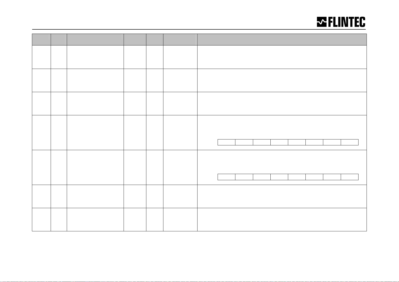
Index Sub-
index
1401 0
1
2
1402 0
1
2
1403 0
1
2
1600
0
1
1601
0
1
1602
0 Number of mapped
1603
0 Number of mapped
Name Type Attri-
bute
Number of elements
COB-ID
Transmission type
Number of elements
COB-ID
Transmission type
Number of elements
COB-ID
Transmission type
Entries in Rx PDO 1
st
Object Cmd. Byte
1
nd
Object Cmd. Byte
2
Entries in Rx PDO 2
st
Object LDM#
1
nd
Object Cmd. Byte.
2
UI8
UI32
UI8
UI8
UI32
UI8
UI8
UI32
UI8
UI8
UI32
UI32
UI8
UI32
UI32
ro
ro
ro
ro
ro
ro
ro
ro
ro
ro
ro
ro
ro
ro
ro
UI8 ro 0 Mapping parameters of the 3
Entries in Rx PDO 3
UI8 ro 0 Mapping parameters of the 4
Entries in Rx PDO 4
Defaultvalue
2
80000300H
+ NodeID
FFH
2
400H +
NodeID
FFH
2
80000500H
+ NodeID
FFH
1
20060108
20060308
1
20060108
20060408
Meaning
nd
Communication parameters of 2
Receive PDO
Determined using the CANopen minimum system ID assignment
procedure.
Asynchronous communication.
rd
Communication parameters of 3
Receive PDO
Determined using the CANopen minimum system ID assignment
procedure.
Asynchronous communication.
th
Communication parameters of 4
Receive PDO
Determined using the CANopen minimum system ID assignment
procedure.
Asynchronous communication.
st
Mapping parameters of the 1
st
Object is ignored by the PC6D.
1
nd
2
Object is a bitwise command:
Receive-PDO
Bit7 Bit6 Bit5 Bit4 Bit3 Bit2 Bit1 Bit0
Cmd: SnG SnN RZ SZ RT ST
nd
Mapping parameters of the 2
st
Object is ignored by the PC6D.
1
nd
2
Object is a bitwise command:
Receive-PDO
Bit7 Bit6 Bit5 Bit4 Bit3 Bit2 Bit1 Bit0
Cmd: TR TS
rd
Receive- PDO (disabled)
th
Receive-PDO (disabled)
Manual PC6D CANopen Page
12
Page 13

Index Sub-
index
1800
0
1
2
3
1801
0
1
2
3
1802
0
1
2
3
1803
0
1
2
3
Name Type Attri-
bute
Number of elements
COB-ID
Transmission type
Inhibit Time
Number of elements
COB-ID
Transmission type
Inhibit Time
Number of elements
COB-ID
Transmission type
Inhibit Time
Number of elements
COB-ID
Transmission type
Inhibit Time
UI8
UI32
UI8
UI16
UI8
UI32
UI8
UI16
UI8
UI32
UI8
UI16
UI8
UI32
UI8
UI16
ro
rw
rw
rw
ro
rw
rw
rw
ro
rw
rw
rw
ro
ro
ro
ro
Defaultvalue
3
180H +
NodeID
FFH
10
3
280H +
NodeID
FFH
10
3
380H +
NodeID
FFH
10
3
80000480H
+ NodeID
FFH
10
Meaning
st
Communication parameters of 1
Transmit PDO
Determined using the CANopen minimum system ID assignment
procedure.
Asynchronous communication.
Transmit inhibit time of PDO in 100 μs steps. A repeated
transmission of the PDO is prevented within the defined interval of
the inhibit time.
Cyclic sending of PDO value (default 20 times / sec.)
nd
Communication parameters of 2
Transmit PDO
Determined using the CANopen minimum system ID assignment
procedure.
Asynchronous communication.
Transmit inhibit time of PDO in 100 μs steps. A repeated
transmission of the PDO is prevented within the defined interval of
the inhibit time.
Event based sending of PDO value (when a dosed value is present)
rd
Communication parameters of 3
Transmit PDO
Determined using the CANopen minimum system ID assignment
procedure.
Asynchronous communication.
Transmit inhibit time of PDO in 100 μs steps. A repeated
transmission of the PDO is prevented within the defined interval of
the inhibit time.
Event based sending of PDO value (when Rx PDO 3 has been
processed by the system)
th
Communication parameters of 4
Transmit PDO
Determined using the CANopen minimum system ID assignment
procedure.
Asynchronous communication.
Transmit inhibit time of PDO in 100 μs steps.
(not used, will not be transmitted)
Manual PC6D CANopen Page
13
Page 14

Index Sub-
index
1A00
0
1
2
3
4
1A01
0
1
2
3
4
1A02
0 Number of mapped
1A03
0 Number of mapped
Name Type Attri-
bute
Number of mapped
Entries in Tx PDO 1
st
Object
1
nd
Object
2
rd
Object
3
th
Object
4
Number of mapped
Entries in Tx PDO 2
st
Object
1
nd
Object
2
rd
Object
3
th
Object
4
Entries in Tx PDO 3
st
Object
1
nd
Object
2
UI8
UI32
UI32
UI32
UI32
UI8
UI32
UI32
UI32
UI32
UI8
UI32
UI32
ro
ro
ro
ro
ro
ro
ro
ro
ro
ro
ro
ro
ro
UI8 ro 0 Mapping parameters of the 4
Entries in Tx PDO 4
Defaultvalue
4
20010220H
20020110H
20020208H
20020308H
4
20010420H
20020110H
20020208H
20020308H
2
20010320H
20020110H
Meaning
st
Mapping parameters of the 1
Transmit-PDO
32 bit Integer (default) or float weight value.
Module Status
-*Module ID [0...63]. The current module scanned.
-*Gateway Status
-*these fields reads 0 (zero) on PC6D
nd
Mapping parameters of the 2
Transmit-PDO
32 bit Integer (default) or float weight value.
Module Status
Data source (0=average,1..4 = set-points).
-*Gateway Status
-*this field reads 0 (zero) on PC6D
rd
Mapping parameters of the 3
Transmit- PDO
32 bit Integer (default) or float tare value.
Module Status
th
Transmit-PDO (disabled)
Manual PC6D CANopen Page
14
Page 15

Index Sub-
index
2000
0
1
2
3
4
5
6
2001
0
1
2
3
4
5
6
7
8
9
A
B
2002
0
1
2
3
2003
0
1..16
Name Type Attri-
bute
Number of entries
Gross weight
Net Weight
Tare
Dosed weight
Dosed tare
Average weight
Number of entries
Gross weight
Net Weight
Tare
Dosed weight
Dosed tare
Average weight
A/D sample
H&B Device ID
H&B FW Version
Device Status
ADC Reference
Number of entries
st
Object
1
nd
Object
2
rd
Object
3
Number of entries
Hardware ID bytes
UI8
REAL32
REAL32
REAL32
REAL32
REAL32
REAL32
UI8
I32
I32
I32
I32
I32
I32
I32
I32
I32
I32
I32
UI8
UI16
UI8
UI8
UI8
UI8
ro
ro
ro
ro
ro
ro
ro
ro
ro
ro
ro
ro
ro
ro
ro
ro
ro
ro
ro
ro
ro
ro
ro
ro
ro
Defaultvalue
6
11
4
16
Meaning
Number of entries in command input array.
Weight values as 32 bit IEEE754 floating point.
Dosed values always read 0 (zero) on PC6D
Number of entries in info array.
Weight and info values as 32 bit signed integer
Dosed values always read 0 (zero) on PC6D
Number of objects in the dosed result.
Module Status
Data source (0=average,1..4=setpoints).
-*Gateway Status
-*this field reads 0 (zero) on PC6D
Number of bytes in hardware identification array.
Manual PC6D CANopen Page
15
Page 16
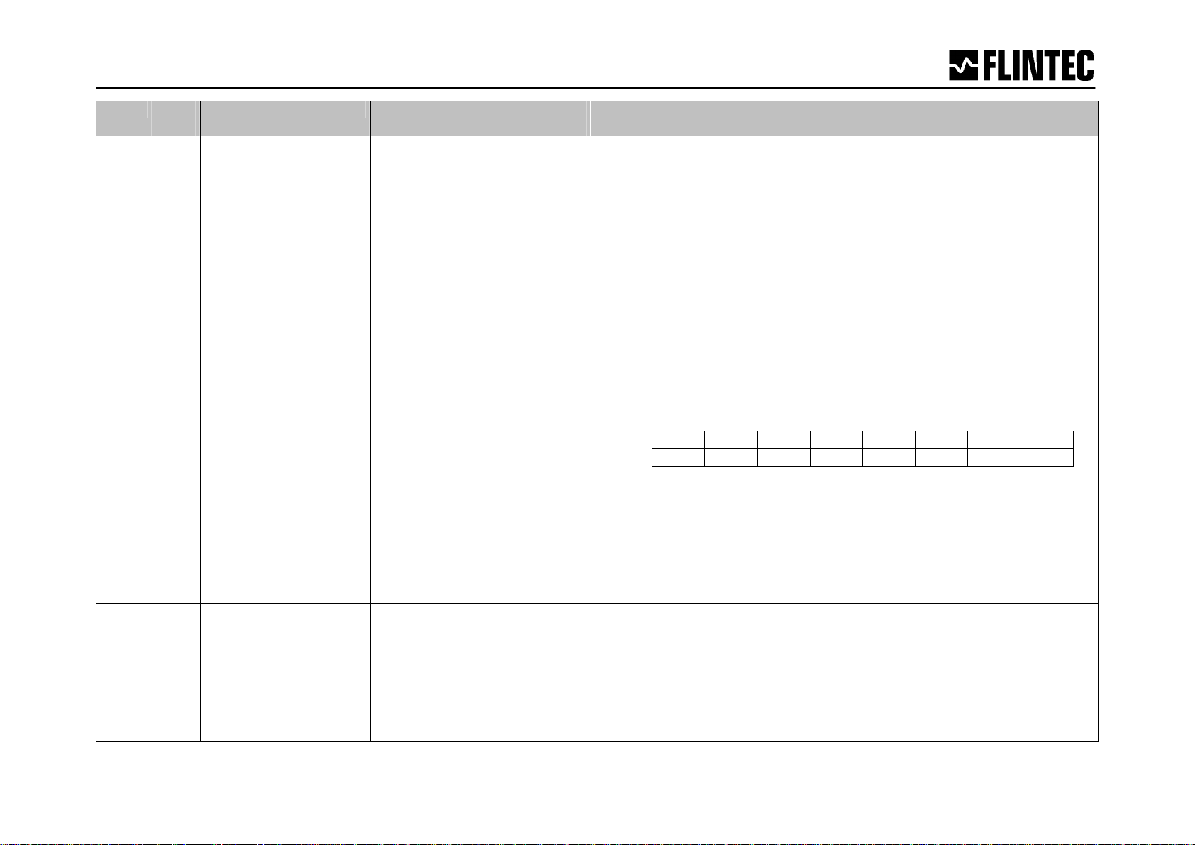
Index Sub-
index
2004
2006
2007
0
1
2
3
4
5
0
1
2
3
4
0
1
2
3
Name Type Attri-
bute
Number of entries.
Save:
Analog output
Calibration
General set-up
Dosing parameters
Set-points
Number of entries
LDM select [0..63]
Factory Default
Direct command 1
Direct command 2
Number of entries
PC6D Bps
PC6D Address
PC6D Bus Config
UI8
UI8
UI8
UI8
UI8
UI8
UI8
UI8
UI8
UI8
UI8
UI8
UI8
UI8
UI8
ro
wo
wo
wo
wo
wo
ro
wo
wo
wo
wo
ro
rw
rw
rw
Defaultvalue
5
4
2
2
1
1
Meaning
Number of parameters.
Save settings;
save analog output parameters (not PC6D),
save calibration settings,
save general set-up parameters,
save dosing setup parameters (not PC6D),
save set-point parameters.
Index 2006 is only for mapping reference (do not access).
Restores the factory defaults, if the TAC is enabled.
Direct bitwise command byte 1 to LDM
Direct bitwise command byte 2 to LDM
Commands bits are:
Bit7 Bit6 Bit5 Bit4 Bit3 Bit2 Bit1 Bit0
Byte1
Byte2 TR TS
Sng,SnN: select Gross or Net in PDO1(tx),
ST,RT: Set/Reset Tare,
SZ,RZ: Set/Reset Zero,
TR: Software trigger,
TS: Trigger Stop.
Number of parameters
Bits/second: 1=1Mbit, 2=500Kb, 3=250Kb, 4=125Kb, 5=50Kb.
CANopen network address 1 … 126.
CANopen configuration: 1=Terminal Resistor ON, 0=Term.Res. OFF
These values are saved to EEPROM when a write occurs to index
2004sub3 (General setup), and takes effect after next power-on.
SnG SnN ST RT SZ RZ
Manual PC6D CANopen Page
16
Page 17

Index Sub-
index
2100
0
1
2
3
4
5
6
7
8
9
A
B
C
D
E
F
10
11
12
13
Name Type Attri-
bute
Number of entries.
st
Parameter
1
nd
Parameter
2
rd
Parameter
3
th
Parameter
4
th
Parameter
5
th
Parameter
6
th
Parameter
7
th
Parameter
8
th
Parameter
9
th
Parameter
10
th
Parameter
11
th
Parameter
12
th
Parameter
13
th
Parameter
14
th
Parameter
15
th
Parameter
16
th
Parameter
17
th
Parameter
18
th
Parameter
19
UI8
I32
I32
I32
I32
I32
I32
I32
I32
I32
I32
I32
I32
I32
I32
I32
I32
I32
I32
I32
ro
rw
rw
rw
rw
rw
rw
rw
rw
rw
rw
rw
rw
rw
rw
rw
rw
rw
rw
rw
Default-
Meaning
value
19 Number of parameters.
-*Analog source
-*Analog high
-*Analog low
Filter setting
-*Filter Factor
-*Digital Outputs
-*Digital Inputs
Measuring Time
Filter mode
No-motion range
No-motion time
-*Digital outputs mask
Tare
Start Delay
Trigger Edge
Trigger Level
Update rate
Zero track (TAC protected)
Δ Time
-*not implemented on PC6D
Manual PC6D CANopen Page
17
Page 18

Index Sub-
index
2300
2500
0
1
2
3
4
5
6
7
8
9
A
B
C
D
0
1
2
3
4
5
6
7
8
Name Type Attri-
bute
Number of entries.
Absolute gain
Absolute zero
Calibrate enable
Calibrate gain
Set calibration point B
Set calibration point A
Calibrate max
Calibrate min
Calibrate save
Calibrate zero
Decimal point
Display step size
Local gravity
Number of entries.
Trigger Level
Trigger Egde
ReTrigWindow
ReTrigTime
HoldTime
TareWindow
TareTime
ReTrigStop
UI8
I32
I32
I32
I32
I32
I32
I32
I32
I32
I32
I32
I32
I32
UI8
I32
I32
I32
I32
I32
I32
I32
I32
ro
rw
rw
rw
rw
rw
rw
rw
rw
rw
rw
rw
rw
rw
ro
rw
rw
rw
rw
rw
rw
rw
rw
Defaultvalue
12
Meaning
Number of calibration parameters.
-*Absolute gain calibrate (TAC protected)
-*Absolute zero calibrate (TAC protected)
Calibrate enable (enables TAC when the TAC is written)
Calibrate gain (TAC protected)
-*Set calibration point B
-*Set calibration point A
Calibrate max (TAC protected)
Calibrate min (TAC protected)
Calibrate save (TAC protected)
Calibrate zero (TAC protected)
Decimal point (TAC protected)
-*Display step size (TAC protect)
Adjust calibration of zero and gain according to new entered gravity
vs. gravity of factory calibration. Remark: Proceeding factory default
(2006 sub 2) changes local gravity back to factory calibration.
-*not implemented on PC6D
8 Number of Check-Weigher parameters
Trigger Level
Trigger Egde
ReTrigWindow
ReTrigTime
HoldTime
TareWindow
TareTime
ReTrigStop
Manual PC6D CANopen Page
18
Page 19

Index Sub-
2600
2700
2800
index
0
1
2
3
4
0
1
2
3
4
0
1
2
3
4
Name Type Attri-
bute
Number of entries.
Set-point 1
Set-point 2
Set-point 3
Set-point 4
Number of entries.
Set-point 1
Set-point 2
Set-point 3
Set-point 4
Number of entries.
Set-point 1
Set-point 2
Set-point 3
Set-point 4
UI8
I32
I32
I32
I32
UI8
I32
I32
I32
I32
UI8
UI8
UI8
UI8
UI8
ro
rw
rw
rw
rw
ro
rw
rw
rw
rw
ro
rw
rw
rw
rw
Defaultvalue
4 Number of Set-point parameters.
4 Number of Set-point parameters.
4 Number of Set-point parameters.
Meaning
Set-point 1 value
Set-point 2 value
Set-point 3 value
Set-point 4 value
Set-point 1 hysteresis
Set-point 2 hysteresis
Set-point 3 hysteresis
Set-point 4 hysteresis
Set-point 1 source
Set-point 2 source
Set-point 3 source
Set-point 4 source
Manual PC6D CANopen Page
19
Page 20
Index Sub-
2900
index
0
1
2
3
4
5
6
7
8
9
10
11
Name Type Attri-
bute
Number of entries
Gross weight
Net Weight
Tare
Dosed weight
Dosed tare
Average weight
A/D sample
Device ID
Firmware Version
Device Status
ADC Reference
UI8
I32
I32
I32
I32
I32
I32
I32
I32
I32
I32
I32
ro
ro
ro
ro
ro
ro
ro
ro
ro
ro
ro
ro
Defaultvalue
11
Meaning
Number of entries in info array.
Weight and info values as 32 bit signed integer
Manual PC6D CANopen Page
20
Page 21

Index Sub-
index
6401
6402
6403
0
1
2
3
4
5
6
0
1
2
3
4
5
6
7
0
1
2
3
4
5
6
Name Type Attri-
bute
Number of entries
Gross weight
Net Weight
Tare
Dosed weight
Dosed tare
Average weight
Number of entries
Gross weight
Net Weight
Tare
Dosed weight
Dosed tare
Average weight
A/D sample
Number of entries
Gross weight
Net Weight
Tare
Dosed weight
Dosed tare
Average weight
UI8
I16
I16
I16
I16
I16
I16
UI8
I32
I32
I32
I32
I32
I32
I32
UI8
REAL32
REAL32
REAL32
REAL32
REAL32
REAL32
ro
ro
ro
ro
ro
ro
ro
ro
ro
ro
ro
ro
ro
ro
ro
ro
ro
ro
ro
ro
ro
ro
Defaultvalue
6 Number of entries in the 16 bit analog input module
7 Number of entries in the 32 bit analog input module
6
Meaning
These entries are mandatory according to DS401. They are the same
as for index 6402, but shifted 8 bits to the right (value/256).
Dosed values always read 0 (zero) on PC6D
These values are the internal long integer representation of the
weight (the integer values are multiplied by 10^dp [2300sub0B]).
Index 6402 is a sub-set of index 2001.
Dosed values always read 0 (zero) on PC6D
Number of entries in the float analog input module
These values are the floating-point representation of the weight as
they are transmitted in the PDO1(tx).
Index 6403 is a replica of index 2000.
Dosed values always read 0 (zero) on PC6D
Manual PC6D CANopen Page
21
Page 22

22
3.5 Quick Start Guide
Notes:
• The PC6D is always quiet on the CANbus until the NMT Start command is received,
except for the very first ‘node guard’ message.
• Default setting for PC6D is CANopen address 1 @ 500 kbit/sec.
3.5.1 Process data objects
TPDO1
Weight values are available at all times (see page 7 or 9)
The following table shows the information of TPDO1 (8 byte, firmware 102.183):
Remark: special firmware (version 102.186) supporting 6 byte available on request
Default : net weight.
Refresh time: every 50 ms per channel, see note below.
Format: Floating point single precision (IEEE 754)
Note:
A timer is controlled by index 1006 which is a silence time after transmission of a TPDO1 in
which no further TPDO1 messages is sent regardless of the output rate from the ADC and
filter system. This timer only applies to TPDO1.
This means that the default filter setting FL=3, type IIR, UR=0 produces 1200 samples. But
the default value 50000 µs in index 1006 means that only every 60th sample is actually
transmitted, the 59 others are blocked by this timer.
On the other hand if you use a FIR filter with FL=8 you will only get a maximum of 150
measurements per second even if you try to set the index 1006 to 100 µs (10kHz). UR will
have the usual effect.
TPDO2
8 byte format as TPDO1, except the “Module Number” contains a code:
0 => Average weight (is available and refreshes when a new value is ready)
1=> Setpoint 1 crossed
2=> Setpoint 2 crossed
3=> Setpoint 3 crossed
4=> Setpoint 4 crossed
32 bit 16 Bit 8 Bit 8 Bit
Weight Module Status Module number Gateway State
Weight Module Status 0 0
Page Manual PC6D CANopen
Page 23

TPDO3
8 byte format as TPDO1. It is sent every time the tare changes and value set is the new tare
value.
RPDO1
The following commands can be executed direct (see Index 1600):
Examples:
- Setting tare for channel 2: transmit RPDO1 [01 08]
- Setting gross weight in TPDO1 for channel 1: transmit RPDO1 [00 128]
32 bit 16 Bit 8 Bit 8 Bit
Weight Module Status 0 0
Bit7 Bit6 Bit5 Bit4 Bit3 Bit2 Bit1 Bit0
Cmd: SG SN ST RT SZ RZ
128 64 08 04 02 01
RPDO2
The following commands can be executed direct (see Index 1601):
Bit7 Bit6 Bit5 Bit4 Bit3 Bit2 Bit1 Bit0
Cmd: TR TS
128 01
Example:
- Setting trigger start for channel 5: transmit RPDO1 [04 128]
3.5.2 Service data objects
SDO’s
Are only available on request
See tables 3.3 Object Directory
Can be used for complete setup of the System MCS-64 via CANbus master, e.g.:
- Filter setting channel 1: Index 2100, Subindex 4
- Filter Mode setting channel 3: Index 2102, Subindex 9
Can be used to get information regarding all the commands available, e.g.:
- Net weight channel 1: Index 2900, Subindex 2
- AD sample channel 3: Index 2902, Subindex 7
Note: Index 2000 and 2001 refer to the CANbus standards (document DS 301, which is
available on request). Using Index 2000 and 2001 you will only get the weight information (no
channel info). Using Index 2900 – 293F you get the weight and channel information.
Manual PC6D CANopen Page
23
Page 24

4 Notes
At PC6D you can download firmware updates:
• via CANopen or
• via PC.
4.1 Firmware Update (via CANopen)
This piece of firmware resides in Flash memory block 0 and 5. Its primary function is
to load new software versions to Flash blocks 1 … 4.
This is used to allow firmware update through the CANbus using a special protocol.
Please ask Flintec for the description.
4.2 Firmware Update (via PC)
For this purpose we have a special programmer software for an easy download of the
firmware. Additional you need a converter “RS232/CANbus” or “USB/CANbus”. We
recommend the a converter “USB/CANbus”.
For CANbus communication via PC (Win2000/XP) with USB-port you can use:
PCAN-USB-Adapter
Supplier: PEAK-System Technik GmbH, D-64293 Darmstadt
article no. IPEH-002021
www.peak-system.com
Page Manual PC6D CANopen
24
Page 25

Part B
5 COMMANDS
These pages describe the ASCII commands as they must be used e.g. by the DOP software.
At each command the equivalent CAN index and sub-index are given for reference.
For better clarity, all commands are divided into groups as described on the following pages.
PART B...............................................................................................................................25
5 COMMANDS................................................................................................................25
5.1 SYSTEM DIAGNOSIS COMMANDS – ID, IV, IS ..........................................................26
5.2 CALIBRATION COMMANDS – CE, CM, DS, DP, CZ, CG, ZT, FD, CS......................27
5.3 MOTION DETECTION COMMANDS – NR, NT.............................................................30
5.4 FILTER SETTING COMMANDS – FM, FL, UR ............................................................31
5.5 SET ZERO/TARE AND RESET ZERO/TARE COMMANDS – SZ, RZ, ST, RT.................33
5.6 OUTPUT COMMANDS – GG, GN, GT, GS ...............................................................35
5.7 SETPOINT COMMANDS - SN, HN, AN.......................................................................36
5.8 COMMUNICATION SETUP COMMANDS – AD, BR, TERMINAL RESISTOR.....................38
5.9 TRIGGER COMMANDS – SD, MT, GA, TE, TR, TL ..................................................39
5.10 TRIGGER SPECIAL COMMANDS– RW, TT, TS, DT, TW, TI, HT...............................42
5.11 SAVE CALIBRATION, SETUP & SETPOINT PARAMETERS COMMANDS – CS, WP, SS...45
Manual PC6D CANopen Page
25
Page 26
5.1 System Diagnosis Commands – ID, IV, IS
Use these commands to get type, firmware version or device status of PC6D. These
commands are sent without parameters.
ID Request of device identity [ 2900sub08 ]
Master (PC / PLC) sends Devices responds
ID D:2010
The response to this request gives the actual identity of the active device. This is particularly
useful when trying to identify different device types on a bus.
IV Request of firmware version [ 2900sub09 ]
Master (PC / PLC) sends Device responds
IV V:0100
The response to this request gives the firmware version of the active device.
IS Request device status [ 2900sub0A ]
Master (PC / PLC) sends Device responds
IS S:067000 (example)
The response to this request comprises of two 3-digit decimal values, which can be
decoded according to the table below:
Leftmost 3-digit value: Rightmost 3-digit value:
1 Signal stable 1 (not used)
2 Zero action performed 2 (not used)
4 Tare active 4 (not used)
8 (not used) 4 (not used)
16 Setpoint 0 active 4 (not used)
32 Setpoint 1 active 4 (not used)
64 Setpoint 2 active 4 (not used)
128 Setpoint 3 active 4 (not used)
The example decodes the result S:067000 as follows:
Signal stable (no-motion) 1
Zero action 2
Output 2 active 64 (only as software value)
Total 67
Note: the bits that are not used are set to zero.
Page Manual PC6D CANopen
26
Page 27
5.2 Calibration Commands – CE, CM, DS, DP, CZ, CG, ZT, FD, CS
Note: TAC represents Traceable Access Code (calibration counter).
CE TAC counter reading [ 2300sub03 ]
With this command you get the TAC counter reading or you can enable a calibration
sequence.
Master (PC / PLC) sends Device responds Result
CE
CE_17 OK
E+00017 (example) Request: TAC-counter CE 17
Calibration sequence active
This command must be issued PRIOR to any attempt to set the calibration parameters
CZ, CG etc. In legal for trade applications the TAC counter can be used to check if critical
parameters have been changed without re-verification. After each calibration the TAC
counter increases by 1.
CM Set maximum output value [ 2300sub07 ]
This command is used for setup the maximum output value. Permitted values are
between 1…200000.
Master (PC / PLC) sends Device responds Result
CM M+30000
CE
E+00017 (example) Request: TAC-counter CE 17
CE_17 OK
CM_50000 OK
Request : CM = 30000
Calibration sequence active
Setting: CM = 50000
This value will determine the point at which the output will change to “oooooo”, signifying
over-range.
Note: The range, in which a scale can be set to zero (SZ) or automatic zero tracking (ZT) is
active, is +/- 2% of CM value.
Factory default: CM = 99999.
DS Display step size [ 2300sub0C ]
This command allows the output to step up or down by a unit other than 1. Permitted
values are 1, 2, 5, 10, 20, 50, 100 and 200.
Master (PC / PLC) sends Device responds Result
DS S+00002
CE
E+00017 (example) Request: TAC-counter CE 17
CE_17 OK
DS_50 OK
Request : display step size 2
Calibration sequence active
Setting: DS = 50
Manual PC6D CANopen Page
27
Page 28
DP Set decimal point position [ 2300sub0B ]
This command allows the decimal point to be positioned anywhere between leftmost and
rightmost digits of the 5-digit output result. Position 0 means no decimal point.
Master (PC / PLC) sends Device responds Result
DP P+00002
CE
E+00017 (example) Request: TAC-counter CE 17
CE_17 OK
DP_0 OK
Request : position of dec. point
Calibration sequence active
Setting: no decimal point
CZ Set calibration zero point [ 2300sub0A ]
This is the reference point for all weight calculations, and is subject to TAC control.
Master (PC / PLC) sends Device responds Result
CE
CE_17 OK
CZ OK
E+00017 (example) Request: TAC-counter CE 17
Calibration sequence active
Zero point set
Factory default: approx. 0 mV/V input signal
CG Set calibration gain (span) value [ 2300sub04 ]
This is the reference point for calibration under load, and is subject to TAC control.
Permitted values are 1…250000.
Master (PC / PLC) sends Device responds Result
CG G+20000
CE
E+00017 (example) Request: TAC-counter CE 17
CE_17 OK
CG_50000 OK
Request : span 20000d
Calibration sequence active
Setting: span 50000d
For calibration an input signal near the display maximum (CM) will give the best system
performance. The minimum calibration load of at least 20% is recommended.
Factory correct calibration default: 200000 d = 2.000 mV/V input signal = 20 kg
ZT Zero tracking [ 2100sub12 ]
This command enables or disables the zero tracking. Parameter = 0 disables the zero
tracking and parameter = 1 enables the zero tracking. Issuing the command without any
parameter returns the current ZT value.
Master (PC / PLC) sends Device responds Result
ZT Z:001
CE
E+00017 (example) Request: TAC-counter CE 17
CE_17 OK
ZT_0 OK
Request : ZT status (ON)
Calibration sequence active
Setting: ZT = OFF
Page Manual PC6D CANopen
28
Page 29
Zero tracking will be performed only on results less than +/-0.5 d at a rate of 0.4 d/sec, where
d = display step size (see DS command). The zero can only be tracked to +/- 2% of maximum
(see CM command).
Factory default: ZT=0
FD Factory default settings [ 2006sub02 ]
This command puts the PC6D back to a known state. The data will be written to the
EEPROM and the TAC will be incremented by 1.
Note: All calibration and setup information will be lost by issuing this command!
Only the factory temperature correction table and serial number are preserved.
Master (PC / PLC) sends Device responds Result
CE
CE_17 OK
FD OK
E+00017 (example) Request: TAC-counter CE 17
Calibration sequence active
Factory default setting
CS Save the calibration values [ 2004sub02 ]
This command results in the calibration values being saved to EEPROM, and causes the
TAC to be incremented by 1.
Master (PC / PLC) sends Device responds Result
CE
CE_17 OK
CS OK
E+00017 (example) Request: TAC-counter CE 17
Calibration sequence active
Calibration values saved
The CS command saves all of the calibration group values, as set by CZ, CG, CM, DS, DP
and ZT. The command returns ERR and has no updating action unless it is preceded by the
CE_XXXXX.
Manual PC6D CANopen Page
29
Page 30
5.3 Motion detection Commands – NR, NT
The motion detection facility provides a means of disabling certain functions whenever a
condition of instability, or “motion”, is detected. The “no-motion”, or “stable” condition is
achieved whenever the signal is steady for the period of time set by NT, during which it
cannot fluctuate by more than NR increments.The stable condition activates the relevant bit
of responses to “Info Status” (IS).
The following functions are disabled if motion is detected: “Calibrate Zero” (CZ) “Calibrate
Gain” (CG) “Set Zero” (SZ) and “Set Tare” (ST).
NR No Motion range [ 2100sub0A ]
This is the range within which the weighing signal is allowed to fluctuate and still be
considered as “stable”. Permitted values are between 0 and 65535.
Master (PC / PLC) sends Device responds Result
NR R+00010
NR_2 OK
WP OK
Request: NR = 10 d
Setting: NR = 2
Setting saved
NR = 2 i.e. fluctuations within a maximum of ± 2 d, in the period NT, will be considered
“stable”.
Factory default: NR = 1.
NT Stabilisation time for in motion band [ 2100sub0B ]
This sets the time (in milliseconds) over which the weight signal is checked to see if it is
“stable” or has “no-motion“. The weight signal has to vary by less than NR divisions over the
time period NT to be considered ‘stable’.
Permitted range 0-65535 milliseconds.
Master (PC / PLC) sends Device responds Result
NT T+01000
NT_500 OK
WP OK
Request: NT = 1000 ms
Setting: NT = 500 ms
Setting saved
If the value of NT =500 milliseconds, the output must not fluctuate more than NR
increments within 500 milliseconds in order to be considered “stable”.
Factory default: NT = 1000 [=1000 ms].
Page Manual PC6D CANopen
30
Page 31
5.4 Filter setting Commands – FM, FL, UR
Using the commands FM and FL, a digital filter type and strength can be set which will
eliminate most of the unwanted disturbances. The command UR is used for the average
building. Please note that these filters are positioned immediately after the A/D Converter and
therefore affect all aspects of the weighing operation.
[Please read the note TPDO1 regarding index 1006 on page 22]
FM Filter Mode FIR / IIR [ 2100sub09 ]
Choose filter mode, permitted values are “0” for IIR and “1” for FIR.
Master (PC / PLC) sends Device responds Result
FM M+00001
FM_0 OK
WP OK
Request: FM = 1 (FIR)
Setting: FM = 0 (IIR)
Setting saved
The digital IIR filter works as a low-pass filter of 2nd order with Gaussian characteristic,
damping is 40 dB/decade; see table mode 0.
The digital FIR filter works as a low-pass filter with quick response; damping see table
mode 1.
Factory default: 0
FL Setup filters [ 2100sub04 ]
Command for setup cut off frequency, permitted values are 0 … 8.
Master (PC / PLC) sends Device responds Result
FL F+00003
FL_1 OK
WP OK
Request: FL = 3
Setting: FL = 1
Setting saved
Filter values can be chosen between 0 and 8, see table below.
FL= 0 means no filter in mode 0 or 1 (command FM).
Factory default: 3
Mode 0 Characteristic (IIR-Filter)
FL
0 no filtering
1 55 18 57 1200
2 122 8 78 1200
3 242 4 96 1200
4 322 3 104 1200
5 482 2 114 1200
6 963 1 132 1200
7 1923 0.5 149 1200
8 3847 0.25 164 1200
Settling time to 0.1%
* Output-rate = 1200/2
(ms)
UR
samples/s ** Antialiasing filter 17 Hz @ 60 dB/dec
3dB Cut-off frequency
(Hz)
**
Damping @300Hz
(dB)
1200
Output-rate*
(samples/s)
Manual PC6D CANopen Page
31
Page 32

Mode 1 Characteristic (FIR-Filter)
FL
0 no filtering
1 47 19.7 48 64 >90 >80 1200
2 93 9.8 24 32 >90 >40 600
3 140 6.5 16 21 >90 >26 400
4 187 4.9 12 16 >90 >20 300
5 233 3.9 10 13 >90 >16 240
6 280 3.2 8 11 >90 >13 200
7 327 2.8 7 9 >90 >11 172
8 373 2.5 6 8 >90 >10 150
Settling time
to 0.1%
(ms)
3 dB Cut-off
(Hz)
**
20 dB
damping at
frequency
(Hz)
1200
40 dB
damping at
frequency
(Hz)
Damping in
the
stopband
(dB)
Stopband
(Hz)
Output rate
max.
(samples/s)
** Antialiasing filter 17 Hz @ 60 dB/decade
Attention: In mode 1 the output rate is dependant on the selected filter level (FL) and will be
automatically adjusted by the PC6D.
UR Set the update rate (average building) [ 2100sub11 ]
This command will define over how many measurements, from the preceeding IIR or FIR
filter, an average will be calculated. The average will be calculated over 2
UR
samples.
Permitted values 0...7 (see table below).
UR 0 1 2 3 4 5 6 7
No. of samples 1 2 4 8 16 32 64 128
Check / adjustment update rate:
Master (PC / PLC) sends Device responds Result
UR U+0001
UR_4 OK
Request: average over 2 samples
Setting: average over 16 samples
Factory default: 0 [no average, = 1200 samples/s]
Remark to Mode 1
Dependency Output Rate - averaging UR - Filter FL
UR Output Rate samples/s
0 1200 1200 600 400 300 240 200 172 150
1 600 600 300 200 150 120 100 85.7 75
2 300 300 150 100 75 60 50 43 37.5
3 150 150 75 50 37.5 30 25 21.4 18.7
4 75 75 37.5 25 18.7 15 12.5 10.7 9.4
5 37.5 37.5 18.7 12.5 9.4 7.5 6.26 5.36 4.68
6 18.7 18.7 9.4 6.26 4.68 3.76 3.12 2.68 2.34
7 9.4 9.4 4.68 3.12 2.34 1.88 1.56 1.34 1.18
FL0
FL1
19.7 Hz
FL2
9.8 Hz
FL3
6.5 Hz
FL4
4.9 Hz
FL5
3.9 Hz
FL6
3.2 Hz
FL7
2.8 Hz
FL8
2.5 Hz
Page Manual PC6D CANopen
32
Page 33
5.5 Set Zero/Tare and Reset Zero/Tare Commands – SZ, RZ, ST, RT
The following commands allow you to set and reset zero and tare values. The zero set during
calibration remains the ‘true zero’ but new ‘current zero’ can be set using the SZ command. If
the SZ command is issued and accepted then all weight values will then be based on the new
‘current zero’. Please remember that zero value will be subject to the Zero tracking function if
enabled.
If the weight signal is not stable (as defined by the No motion range NR and the No
motion time NT) then both the set zero SZ and set tare ST commands will be disabled.
Also the Set Zero SZ command is not allowed if the new zero value required and the
‘calibration zero’ differ by more than 2 % of the CM value (maximum allowable value).
SZ Set Zero RPDO1 [ 00 02 ]
This command sets a new “current zero” which is then the basis of all weight values until
further updated by the zero tracking function, another SZ command or the “reset zero”
command RZ. The SZ command will fail (LDU responds with ERR) if the new “current zero” is
more than 2% (of the CM value) higher or lower than the “true zero” set during calibration.
The SZ command will also fail if the weight signal is not stable as defined by the No motion
range (NR) and the No motion time (NT). If the weight signal is “stable”, the response to the
IS command (Device Status) will show the “signal stable” bit active and the SZ command will
be accepted (OK). If the “signal stable” bit is not active, the SZ command will be rejected and
the LDU will respond with ERR (error).
Master (PC / PLC) sends Device responds Result
SZ OK
Set Zero performed
The SZ command is issued without any parameters and will return either the OK or ERR
response. If the SZ command is accepted the PC6D responds with OK and the “zero action
performed” bit of the device status (IS) response will be active.
Is the command acknowledged by the PC6D with OK, the status bit for Zero (request IS) is
set to 1. A renewed SZ command or the reset zero command [ RZ ] changes the current zero
point. The command is not implemented, if the current measured value is more than ±2% of
the maximum display value [ CM ] of calibrated zero point [ CZ ].
PC6D response is ERR (error).
RZ Reset Zero Point RPDO1 [ 00 01 ]
This command cancels the SZ command and the zero reading reverts to that set by the CZ
command during calibration.
Master (PC / PLC) sends Device responds Result
RZ OK
The PC6D responds to the RZ command with either OK or ERR. If OK is returned then the
“zero action performed” bit in the Device Status (IS) response will be set to “0”.
Zero point CZ active again
Manual PC6D CANopen Page
33
Page 34
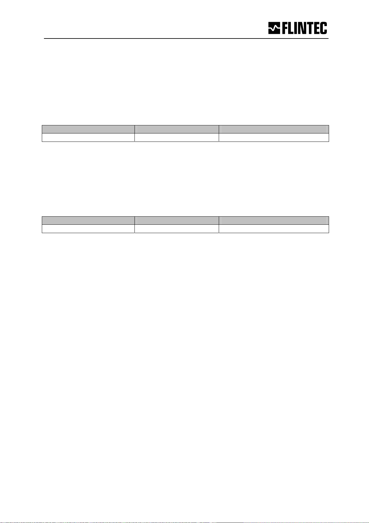
ST Set Tare RPDO1 [ 00 08 ]
This command will activate the net weighing function by storing the current weight value as a
tare.
The weight signal must be “stable” within the limits set by NR (No Motion Range) and NT (No
Motion Time) commands for the “signal stable” bit to be active and set tare command to be
accepted.
Master (PC / PLC) sends Device responds Result
ST OK
Tare performed
If the weight signal is “stable”, the response to the IS command (Device Status) will show the
“signal stable” bit active and the ST command will be accepted (OK). If the “signal stable” bit
is not active, the ST command will be rejected and the LDU will respond with ERR (error).
RT Reset Tare RPDO1 [ 00 04 ]
The weighing signal returns to gross mode.
Master (PC / PLC) sends Device responds Result
RT OK
Tare deactivated
The PC6D responds to the RT command with either OK or ERR. If OK is returned then the
“tare active” bit in the Device Status (IS) response will be set to “0”.
Page Manual PC6D CANopen
34
Page 35
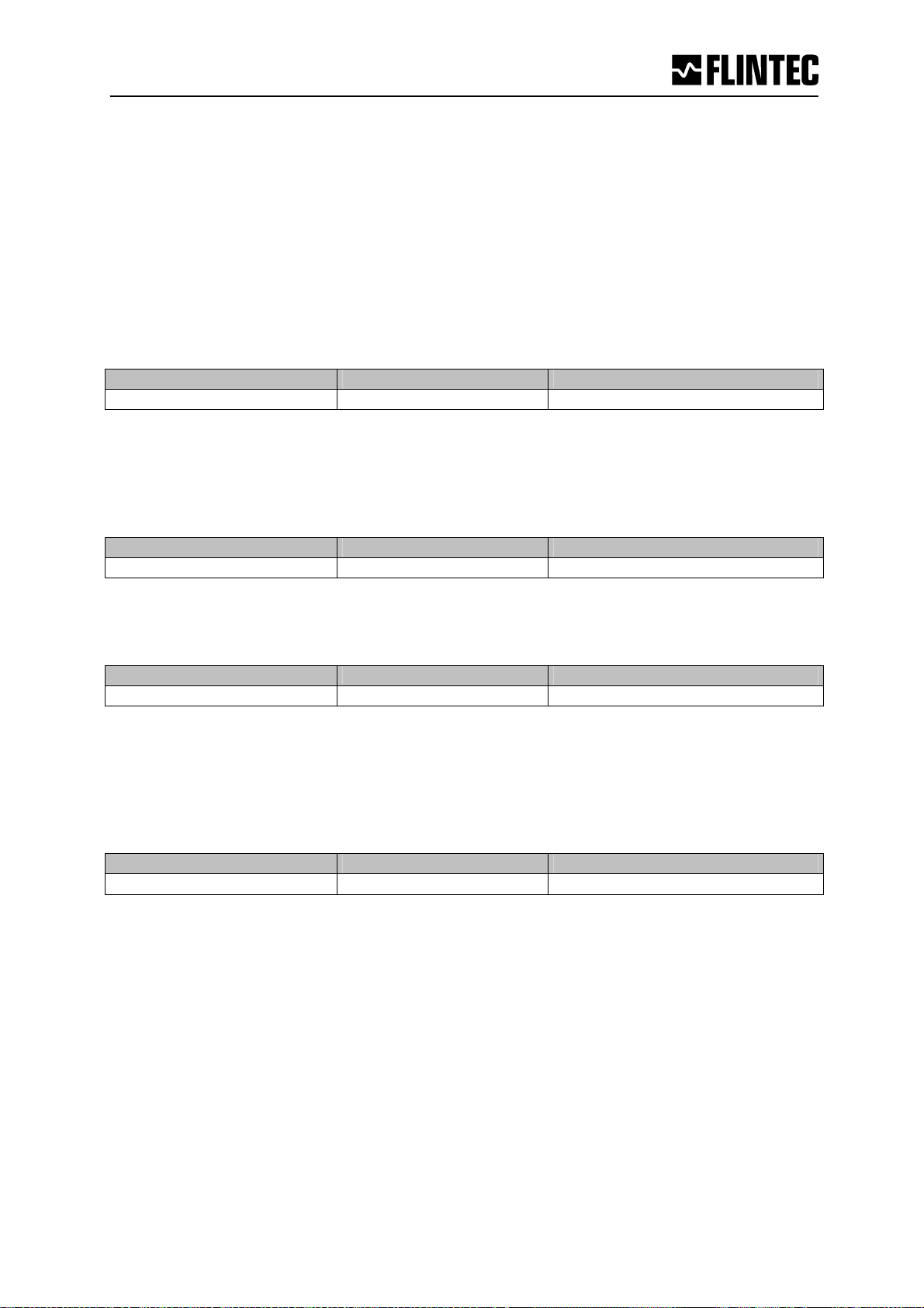
5.6 Output Commands – GG, GN, GT, GS
The following commands “Get” the Gross, Net, Tare and ADC (Sample) values from the
PC6D. Available on the CAN profile index 2000 and 2001 in floating point and integer
respectively.
GG Get Gross value [ 2000/2001sub01 ]
Normally sent in TPDO1, if selected by index 1A00sub01.
Master (PC / PLC) sends Device responds Result
GG G+01.100
Gros weight 1.100 d
GN Get Net value [ 2000/2001sub02 ]
Normally sent in TPDO1, if selected by index 1A00sub01.
Master (PC / PLC) sends Device responds Result
GN G+01.000
Net weight 1.000 d
GT Get Tare value [ 2000/2001sub03 ]
Master (PC / PLC) sends Device responds Result
GT T+00.100
Tare weight 100 d
GS Get ADC Sample value [ 2900sub07 ]
This command gets the actual Analogue to Digital Converter (ADC) value. This can be useful
during development or when calibrating to see how much of the ADC range is being used.
Master (PC / PLC) sends Device responds Result
GS S+125785
AD-value = 125.785 d
For service applications, it is helpful to note the GS values for the “no-load” or “zero” output
and when the “calibration load” is applied.
Manual PC6D CANopen Page
35
Page 36
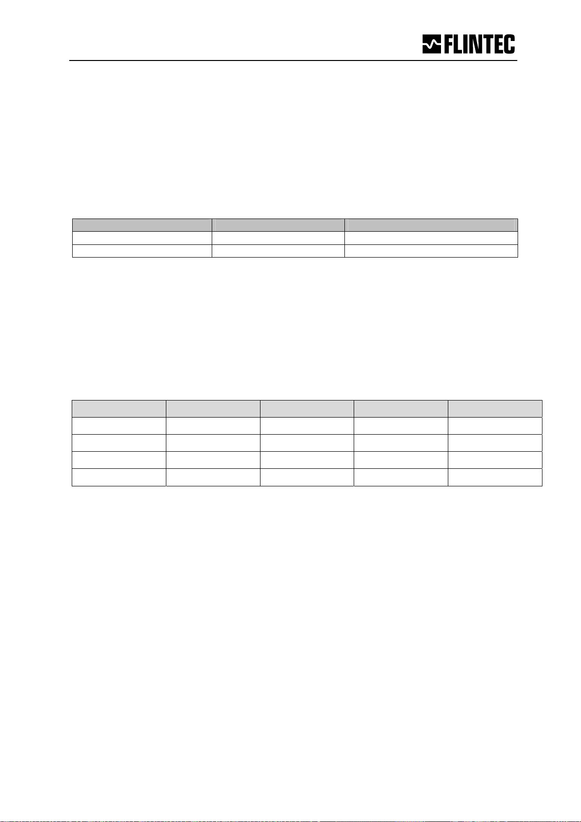
5.7 Setpoint Commands - Sn, Hn, An
The PC6D has 4 setpoints where the status is dependent on the weight value. Each of them
can be assigned as an independent setpoint value (Sn) with a corresponding
hysteresis/switch action (Hn) and base (An – switch on the gross or the net weight).
S1 Setpoint 1 [ 2600sub01 ]
Request / Setting
Master (PC / PLC) sends Device responds Result
S1 1+01500
S1_03000 OK
Setpoint S1 = 1500 d
Setting: Setpoint S1 = 3000 d
Similarly to read or set setpoint 2, use S2 instead of S1, etc. (2600sub02)
H1 Hysteresis setpoint 1 [ 2700sub01 ]
Using the H1 command, the hysteresis on the setpoint value is set by the numeric value and
the polarity of this numeric value defines whether the setpoint switches on or off when the
setpoint value is reached.
Example
Setpoint Hysteresis Load OFF ON
S1 = 20.00 kg H1 = -1.00 kg increasing ≥ 21.01 kg 0 ... 21.00 kg
S1 = 20.00 kg H1 = -1.00 kg decreasing ≥ 20.00 kg 19.99 ... 0 kg
S1 = 20.00 kg H1 = 1.00 kg increasing 0... 19.99 kg ≥ 20.00 kg
S1 = 20.00 kg H1 = 1.00 kg decreasing 19.00. ..0 kg
≥ 19.01 kg
Example of negative hysteresis of 1.00 kg (H1 = -100) on a setpoint (S1) of 20.00 kg
(lines 1 & 2 of table above):
When the weight is increasing between 0 kg and 21.00 kg the setpoint is “ON”. Once the
weight increases above 21.00 kg then the logic output is “OFF”. The setpoint will come “ON”
again when the weight value drops below 20.00 kg.
Example of positive hysteresis of 100 kg (H1 = +1.00) on a setpoint of 20.00 kg
(lines 3 & 4 of table above):
When the weight is increasing between 0 kg and 19.99 kg the setpoint is “OFF”. Once the
weight increases above 19.99 kg then the setpoint is “ON”. The setpoint will switch “OFF”
again when the weight value drops below 19.00 kg.
Page Manual PC6D CANopen
36
Page 37
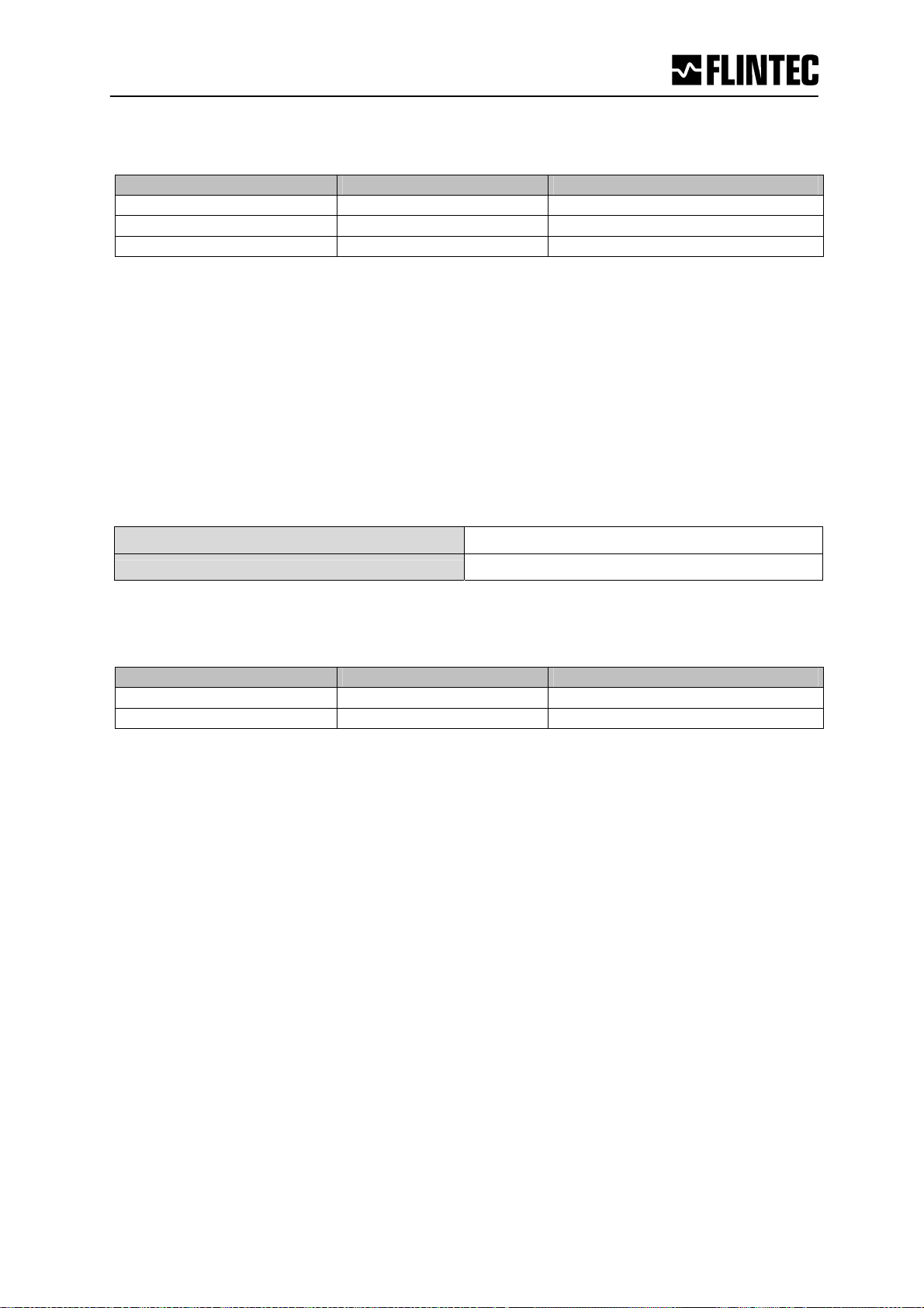
Request / Set Hysteresis value for setpoint 1
Master (PC / PLC) sends Device responds Result
H1 1-00100
H1_100 OK
H1_-100 OK
Request: neg. Hysteresis
Setting: pos. Hysteresis
Setting: neg. Hysteresis
Setpoint range between ± 1 (minimum) and ± 199999 (maximum).
Similarly to read or set the setpoint 1 hysteresis, use H2 instead of H1 etc. (2700sub02)
A1 Request / Set the base for setpoint 1 [ 2800sub01 ]
The A1 command defines the base on which the setpoint value acts. If A1 is set to “0”
then setpoint 1 acts on the unfiltered gross weight. If A1 is set to “1” then setpoint 1 acts on
the unfiltered net weight.
A1 = 0
A1 = 1
Not filtered gross weight
Not filtered net weight
Request / Set base for setpoint 1
Master (PC / PLC) sends Device responds Result
A1 1+00000
A1_1 OK
Allocation gros weight
Allocation net weight
Similarly to read or set the setpoint 1 base, use A2 instead of A1 etc. (2800sub02)
The PC6D transmits one TPDO2 every time a setpoint changes state. The weight sent in the
TPDO2 is the weight that caused the TPDO2 to be transmitted, Net or Gross as selected for
the actual setpoint. The TPDO2 also holds the Weighing status flags and the setpoint
Number.
If two (or more) setpoint have exactly the same settings the setpoint with the higher number
will be “hidden”.
NOTE: All changes to the setpoint settings have to be stored in EEPROM using the SS
command. See section 5.10.
Manual PC6D CANopen Page
37
Page 38
5.8 Communication setup Commands – AD, BR, Terminal Resistor
NOTE: These settings will only take effect after a power on reset (remember to store the
settings using the WP command [2004sub03] before turning the power off.)
AD Device address setup / request [ 2007sub02 ]
It is possible to set the network address of the device using the AD command. (Address
range between 1 and 126).
Note: Setting the device address to 0 or 127 are not allowed. Address 0 is used by the
Network Management Protocol (NMT).
Request
Master (PC / PLC) sends Device responds Result
AD A:001
AD_49 OK
Factory default: Address 1
Request: Address 1
Setting: Address 49
BR Request / Setup CAN Speed [ 2007sub01 ]
With this command the following bits/second rates can be setup:
- 1 = Mbit
- 2 = 500 kbit/s
- 3 = 250 kbit/s
- 4 = 125 kbit/s
- 5 = 50 kbit/s
Master (PC / PLC) sends Device responds Result
BR B:001
BR_2 OK
Request: CAN speed 1 Mbit /s
Setting: CAN speed 500 kbit/s
Factory default: 500 kbit/s.
Terminal Resistor ON / OFF [ 2007sub03 ]
A build in terminal resisitor is switchable via CANopen
- 1 = ON
- 0 = OFF
Factory default: ON.
Page Manual PC6D CANopen
38
Page 39
5.9 Trigger Commands – SD, MT, GA, TE, TR, TL
Note: All setups should be stored with the WP command before power off.
SD Start Delay [ 2500sub0A ]
Set the delay between falling/rising edge of trigger pulse and start of measurement.
Permitted values are 0 … 65535 ms.
Master (PC / PLC) sends Device responds Result
SD S+00100
SD_200 OK
Request: SD=100 ms
Setting: SD=200 ms
Factory default: 0 [= 0 ms]
MT Measuring Time [ 2500sub09 ]
Set the time over which the average value will be built.
Permitted values are 0 …65535 ms.
Master (PC / PLC) sends Device responds Result
MT M+00100
MT_500 OK
Request: MT=100 ms
Setting: MT=500 ms
Note: MT = 0 means disabled trigger and average function.
Factory default: 0
GA Get Average [ 2900sub06 ]
Issuing the GA command the PC6D returns the latest average weight value by using the MT
setup. On PC6D it is not necessary to ask for this. The average result is sent in a TPDO2
when ready, or re-triggered.
Master (PC / PLC) sends Device responds Result
GA A+01.100
Answer: GA=1.100 g
Note: During the time between the trigger condition being accepted and the average
value being updated, the GA command will return the value 99999 when it has been
triggered or 88888 when it has been retriggered or 99996 when the system tried to
change Tare or Zero before end of measurement.
[ Remark: When started this function, the latest average weight is availabe in TPDO2. ]
Manual PC6D CANopen Page
39
Page 40
TL Trigger Level [ 2500sub01 ]
Set the trigger level for rising edge start of measurement. Permitted values are in the
range 0…262143.
Master (PC / PLC) sends Device responds Result
TL T+99999
TL_1000 OK
With regard to the trigger commands SD and MT, a check weighing will automatically start
when the weight overshoots by e.g. 1.000d (increments), e.g. 100,0 g.
Factory default: 199999
TE Trigger Edge [ 2500sub02 ]
Issuing the TE command selects rising or falling edge trigger. Parameter = 0 select falling
edge and parameter = 1 select rising edge.
Request: TL=99999
Setting: TL=1000
Master (PC / PLC) sends Device responds Result
TE E:001
TE_0 OK
Factory default: 0 [falling edge]
Note: This command cannot be used together with the TL command.
TR Trigger RPDO2 [ 00 80 ]
[This command will start the measuring cycle in the same way as the hardware trigger
input.]
Master (PC / PLC) sends Device responds Result
TR OK
Request: TE=1
Setting: TE=0
Trigger started
Note: This function can be used as a soft trigger in a check weigher application (firmware
102.183).
[ Special returned values are:
- 99999 = trigged measurement in progress
- 88888 = Re-Trigger in progress
- 99996 = Tried to change Tare or Zero before end of measurement ]
[ The Trigger function can also be stopped by sending 01 instead of 80 with RPDO2 [00 01]. ]
Factory default: 199999
Page Manual PC6D CANopen
40
Page 41

t
Basic settings
DX : 1 (full duplex)
UR : 0 (max. 600 meas./s)
TL : 65535 (off)
Typ. Checkweigher settings
RT : 65535 (off)
TW : 10 d
TI : 200 ms
SD : 100 ms
MT : 300 ms
FL : 2 (8 Hz)
MT
Measuring T im e
SD
Start Delay
Typical Checkweigher Signal
Trigger point
choose 1 of 3:
1. Light barrier or
2. TR command or
3. TL Trigger Level
TI
M
(g)
Tare Interval
Tare
TW
Window
Manual PC6D CANopen Page
41
Page 42
5.10 Trigger Special Commands– RW, TT, TS, DT, TW, TI, HT
Remark: These commands are only available in firmware 102.183.v.1.10.
Note: All setups should be stored with the WP command before power off.
RW Re-Trigger Window [ 2500sub03 ]
Set the re-trigger window in counts (digits) without decimal point. If the weight relative to the
current average value changes by more than the RW value the average cycle will be
restarted using TT as measure time.To automatically issue the re-trigger command, the time
period over which an increase of weight average is measured has to be defined by using the
command DT. Permitted values are 0 …65535 counts.
Master (PC / PLC) sends Device responds Result
RW R+65535
RW_500 OK
Factory default: 65535
TT Re-Trigger Time [2500sub04 ]
Set the re-trigger time in milliseconds [ms]. Re-trigger time is the average time used by the re-
trigger function. If set to zero the re-trigger function is disabled.
Permitted values are 0 …65535 ms.
Master (PC / PLC) sends Device responds Result
TT T+65535
TT_300 OK
Factory default: 65535
TS Re-Trigger Stop [ 2500sub08 ]
Set the re-trigger stop in counts (digits) without decimal point. In case of a (TS) decrease in
weight relative to the current average value the re-trigger function is stopped.
Permitted values are 0 …65535 counts.
Master (PC / PLC) sends Device responds Result
TS T+00000
TS_480 OK
Factory default: 00000
[ The Re-Trigger function can also be stopped by sending 01 instead of 80 with
RPDO2 [00 01]. ]
Request: RW=65535
Setting: RW=500d
Request: TT=65535
Setting: TT=300ms
Request: TS=00000
Setting: TT=480d
Page Manual PC6D CANopen
42
Page 43
DT Delta Time [ 2500sub0B ]
Set the Delta Time in milliseconds [ms]. During MT and TT timeframes "sub-averages" will be
calculated by the system over the time DT. If a sub-average is outside the re-trigger window,
the re-trigger function is automatic started. Permitted values are 0 …65535 ms.
Master (PC / PLC) sends Device responds Result
DT T+00000
DT_50 OK
Factory default: 00000
Request: DT=00000
Setting: TT=50ms
TW Tare Window [ 2500sub06 ]
Set the Tare Window in in counts (digits) without decimal point. Tare window (TW) allows an
automatic Tare update. If TW = 0 this function is not active. If TW = 100, this means a new
tare value will be taken when the net average weight of an empty scale is within 100 counts
or division of zero. The new average tare value is calculated over the average tare time
defined by TI. If the tare average is outside tare window, the tare will not be updated.
Permitted values are 0 …65535 counts.
Master (PC / PLC) sends Device responds Result
TW T+00000
TW_100 OK
Factory default: 00000
TI Tare Time [ 2500sub07 ]
Set the Tare Time in milliseconds [ms]. During the Tare Time a “tare-average” will be
calculated by the system. Permitted values are 0 …65535 ms.
Master (PC / PLC) sends Device responds Result
TI T+00000
TI_200 OK
Factory default: 00000
HT Hold Time [ 2500sub05 ]
Set the Hold Time in milliseconds [ms]. During the Hold Time the weight value must be over
setpoint that a digital output can be switched. This means that a short signal peak will not
lead to the switching of a digital output. Permitted values are 0 …65535 ms.
Master (PC / PLC) sends Device responds Result
HT T+00000
HT_200 OK
Factory default: 00000
Request: TW=00000
Setting: TW=100d
Request: TI=00000
Setting: TI=200ms
Request: HT=00000
Setting: HT=200ms
Manual PC6D CANopen Page
43
Page 44
5.11 Save calibration, setup & setpoint parameters Commands – CS, WP, SS
The setup and calibration parameters can be divided into 3 groups:
Calibration parameter: CZ, CG, DS, DP & ZT are saved by the CS command.
Setup parameters (other than setpoint): FL, FM, NR, NT, BR, AD, etc. are saved by the
WP command.
Setpoint parameters: Sn, Hn and An are saved by the SS command.
CS Save the calibration parameters [ 2004sub02 ]
Note: Calibration parameters can only be saved if the TAC code is known and precedes the
CS command. See the CE and CS commands on page 27 / 29.
Both the setup parameters and the setpoint parameters are stored in EEPROM using the WP
and SS commands respectively.
WP Save the setup parameters [ 2004sub03 ]
With this command the settings of the “Filter” (FL, FM) , the “No-Motion” (NR, NT) and the
communication (AD, BR) will be saved in the EEPROM.
Master (PC / PLC) sends Device responds Result
WP OK
WP ERR
Parameter saved
Error
SS Save the “setpoint” set-up parameters [ 2004sub05 ]
With this command the settings of the setpoints (Sn), the “setpoint hysteresis” (Hn) and the
“setpoint action” (An) will be saved in the EEPROM.
Master (PC / PLC) sends Device responds Result
SS OK
SS ERR
Parameter saved
Error
Manual PC6D CANopen Page
45
Page 45

DDEECCLLAARRAATTIIOONN OOFF CCOONNFFOORRMMIITTYY
ß
0
Product: Digital load cell
Manufacturers designation:
Manufacturer:
As manufacturer of the article we herewith assures that the article meets the requirements of
the European legislation covering technical instruments, the standard safety rules, other
safeguard regulations as well as the generally approved rules for technical safety,
environmental protection and electromagnetic compatibility. It is further assured that the
articles are in accordance with the supporting documents as supplied by the manufacturer.
To ensure this the necessary monitoring measures during production have been met.
We, the manufacturer, are under obligation to produce to relevant parties upon request
written supporting evidence or by other means i.e. factory visits, spot checks etc. that the
production requirements have been met.
Electronic articles have been manufactured and tested according to the following regulations:
Safety regulations:
PC6D
Flintec GmbH, Bemannsbruch 9, DE74909 Meckesheim,
Germany
CENELEC EN 60742
Electromagnetic Compatibility:
and further requirements as listed in the order specifications as agreed upon.
Meckesheim, April 20, 2007
Signature:
i.V. Gisbert Greulich
Being the responsible person employed and appointed by Flintec GmbH
EN 55011 and EN 61000.
 Loading...