

Page 1

FLINTEC
REMOTE DISPLAY TERMINAL
FDT
VERSION A/B
TECHNICAL -REFERENCE MANUAL
Flintec GmbH
Bemannsbruch 9
74909 Meckesheim
Germany
Tel. +49 6226 92400
Fax. +49 6226 924099
www.flintec.net
[email protected]
Document
FDT – VERSION A/B – TECH. -REFERENCE MANUAL
Date
05.04.99
FDT.RM
Code
Rev.
Page
2
of 23
1
Page 2

FLINTEC
TABLE OF CONTENTS
PAGE
1. INTRODUCTION 3
2. FRONT PANEL DESCRIPTION 4
3. INSTALLATION 6
3.1. MOUNTING 6
3.2 WIRING 6
3.3. AC POWER
4. OPERATING MODES 7
4.1 REMOTE DI SPLAY (Continuous weight input) 7
4.2 MASTER DISPLAY AND KEYBOARD FOR FAD-1 /-4 7
4.3 SLAVE DISPLAY FOR FAD 8
4.4 DUAL FAD MASTER MODE ( Scale A/B ) 8
5. SETUP AND CALIBRATION 9
5.1. FDT CONFIGURATION 9
5.2 FAD CONFIGURATION 11
5.3 CUSTOM PRINT FORMATS 15
6. FUNCTION MENU 16
7. ERRORS 18
8. COMMUNICATIONS 19
8.1 SERIAL PORT 1
8.2 SERIAL PORT 2
9. SPECIFICATIONS 23
9.1 MAINTENANCE
9.2 SERVICE
This manual contains pr oprietary information, protected by international copyright laws.
No part of this document maybe reproduced without the written agreement of the publisher, Flintec GmbH.
The information herein is believed to be both accurate and reliab le. Flintec GmbH, however, would
be obliged to be informed if any errors occur. Flintec GmbH cannot accept any liability for direct or
indirect damages resulting from the use of this manual.
Flintec GmbH reserves the right to revise this manual and alter its content without notification.
6
Document
FDT – VERSION A/B – TECH. -REFERENCE MANUAL
Date
05.04.99
FDT.RM
Code
Rev.
Page
2
of 23
2
Page 3

FLINTEC
1. INTRODUCTION
FDT is a Remote Display Terminal specifically designed for use as remote weight indicator for
Digital Junction Box weigh systems (FAD-1 or FAD-4).
The unit maybe operated in the Master mode where it will poll all (max 30) FAD’s connected to it,
or in the Slave mode where it will only display information from a selected FA D.
Setup and Calibration of FAD’s is performed via FDT in the Master mode.
When several (max 30) FAD’s and FDT’s are connected on one cable, only one FDT is allowed to
poll the FAD’s. Communication in a master/slave network is based on LESIP serial interface protocol.
The unit may also be used as remote display for numeric indicators with continuous weight output
mode (LECW _ 2 format).
FDT may be used for legal for trade app lications when connected with one or more weigh scales,
since calibration data is stored in th e FAD.
The basic configuration VERSION A includes:
1. Serial port RS485A with network capability.
2. Front panel with 6 digit LED display plus 5 annunciators and 6 membrane keys.
3. Non volatile memory for system parameters and calibration data.
4. The setting of the unit is done through a guided keyboard operation, enabling the adaptation
to operating environment and system requirements. Two setup procedures are executed. Fn 49
for calibrating the FAD and Fn 4 6 for settin g up op eration mode and communication parameters
of FDT.
The advanced configu r ation (VERSION B) includes additionally:
1. Real time clock calendar with rechargeable battery backup.
2. Serial port RS232 adapter for printing weighing data on a serial printer and /or
bidirectional communication with a host computer.
3. Non volatile memory for storage of 10.000 weights.(Electronic tally roll or Alibi memory).
OPTIONS
OP.5 230 VAC to 9 VAC/ 500mA, mains power adapter.
OP.7 RS232C/RS485A converter including power adapter 230 VAC to 8 VAC/ 500mA.
OP.8 Bracket (Table top Wall mount) for the p anel version.
OP.9 Custom software on request.
ENCLOSURES
P Panel mount 72 x 144 x 70 mm
S Stainless steel 180 x 108 x 60 mm.
EXTENT OF SUPPLY
The standard supply includes:
The connection plug for the communication cable. The reference manual.
Prior to unpacking the equipment, examine the carton for exterior shipping damage.
If any notify the carrier immediately. Remove the equipment from the carton and plastic bag.
Inspect extent of supply for any sign of damage. Save packaging material.
Document
FDT – VERSION A/B – TECH. -REFERENCE MANUAL
Date
05.04.99
FDT.RM
Code
Rev.
Page
2
of 23
3
Page 4

2. FRONT PANEL DESCRIPTION
FLINTEC
1. WEIGHT DISPLAY
6 digit LED for the display of measured weight (gross or net), and error messages.
Digit height approx. 14mm.
OVERARANGE is indicated by vvvvvv
UNDER-RANGE is indicated by uuuuuu
Scale not level will be indicated by E t i l t
2. NET INDICATOR
If lights up when the scale has been tared and the display is in NET mode.
3. TARE INDICATOR
It indicates that a tare value is being displayed.
4. NO MOTION INDICATOR
It lights up when the scale is stable.
5. CENTER OF ZERO INDICATOR
It lights up when the scale weight is stable and within 1/4 division of actual zero.
6. SCALE A INDICATOR
In ‘ dual scale mode’ it indicates the weigh t from scale A is displayed.
ON = Scale A is displayed OFF = Scale B is displayed
7. SCALE B INDICATOR
In ‘dual scale mode’ it indicates the weight from scale B is displayed.
ON = Scale B is displayed OFF = Scale A is displayed
When both scale A & B LEDs are illuminated the sum of the weight A+B is display ed.
vvvvvv
vvvvvvvvvvvv
uuuuuu
uuuuuuuuuuuu
Document
FDT – VERSION A/B – TECH. -REFERENCE MANUAL
Date
05.04.99
FDT.RM
Code
Rev.
Page
2
of 23
4
Page 5

8. ZERO / CLEAR ERROR / ESCAPE KEY
- It is used to reset the weight display to zero. Zeroing will be effective only if the
scale is stable, in gross mode, and the weight is within +
- If an error is present on the display press this key to acknowledge.
9. TARE KEY (toggle)
- It is used to tare the scale. Taring will be effective only if the scale is stable and
within the weighing capacity.
- If the scale has already been tared depression of the key will cause the tare to be
cancelled and the weight display to return to Gross mode.
10. TARE RECALL KEY
- Pressing this key will cause the tare memory to be displayed briefly.
- In “DUAL SCALE” mode the key switches between scale A or scale B or SUM (A+B).
11. PRINT – ACCUMULATE
It is used to transmit weight data to periph eral devices via the serial port 1.
The transmitted weight will also be accumulated. The weight will be printed only if it is
stable and within the weighing range of the indicator.
Printing and / or accumulation will take place only if enabled in set up.
The weight data printed is selectable in SET UP 2. 2t. Refer to the technical manual
for details.
12. TOTAL KEY
It is used to display the current accumulated total.
Press again to see the number of weighings.
Press again to end the total display or
Press to print/delete the total.
13. FUNCTION KEY
Enables a selection of software utilities 00 – 99.
Fn 00 appears on the display. Use keys to increment the flashing digit, to change digit.
When the correct number is displayed press . The selected function will be activated.
Refer to chapter 6 Fun ction menu for details of available utilities.
FLINTEC
2% of max weighing capacity.
Document
FDT – VERSION A/B – TECH. -REFERENCE MANUAL
Date
05.04.99
FDT.RM
Code
Rev.
Page
2
of 23
5
Page 6

FLINTEC
3. INSTALLATION
3.1. Mounting
The mounting location must be such that the instrument is not subject to excessive vibrations,
heat or humidity. Avoid direct sunlight on the front of the instrument.
The unit has to be installed at the right height to allow an easy reading of the display and keyboard
operation.
3.2 Wiring
Use 4 x 0,34 mm
for RS485A connection.
PANEL MOUNT
All connections to the instru men t are mad e through the rear panel connector. Strain reliefs are supplied
with the connectors. See connector diagram in Annex A .
STAINLESS STEEL
-Remove the rear panel by undoing the 4 screws. Lift the rear panel carefully.
-Insert cables via the cable glands. Strip and connect the power leads to J1, the RS485 leads
to J2 and RS232 leads to J3. (See connector diagram in Annex A). Connect the shields
of the cables on the ground tag provided.
-Re-install the rear panel. Tighten the screws until the rear panel touches the front panel.
-Tighten the strain relief’s to ensure a firm grip on the cables.
3.3. Power
As the instrument is computer controlled it requires clean power for reliable operation.
Power supplied should come from a source that is isolated from other process equipment.
A main adapter of 7,5 – 10 VAC / 500 mA is recommended for operation of both the FDT and FAD-4.
3.4 Power up
When the unit is powered up it goes through a series of self tests after which the following
is displayed in sequence.
- Version code
- Revision date
- All display segment are turned on then off for 1 sec. Then it goes into the
operating mode. If an error is encountered it will be displayed in the form E xx .
Refer to chapter 7 Errors for details.
CAUTION : Do not run signal cables together with power cables.
2
screened for RS232C connection and 2x0,34 mm2 twisted pair and shielded
Connect the shielding where indicated on the drawing only.
Never use a meg ger to check wiring.
Be sure the AC power socket outlet is properly protected.
For optim um EMC performance, keep the length of shield inside the
enclosure as short as possible.
Document
FDT – VERSION A/B – TECH. -REFERENCE MANUAL
Date
05.04.99
FDT.RM
Code
Rev.
Page
2
of 23
6
Page 7

FLINTEC
4. OPERATING MODES
FDT may be configured accordin g to the applications, to be operated in 4 different modes.
4.1 REMOTE DISPLAY - CONTINUOUS WEIGHT INPUT
The unit displays information received from the serial port(s) according to LECW_2 format
(P + 123.45 “CR”). RS485A may be received from port 1 (Version A or B). Baudrate and data
bits are programmable in SETUP 3.
RS232C may be received from port 2 (Version B only). Baudrate is fixed at 1200 baud. No or
even parity and 7 or 8 data bits are programmable in SETUP 2. 20 mA , current loop passive may
be connected to the RS232 port (Tx+ to Tx and Tx– to Rx).
SET UP REQUIREMENTS (Port 1 9600, E, 7, 1 or Port 2 1200, E, 7, 1)
1 Don’t care
2 2d = 17, the rest set to Zero
3 3t = 01, 3b = 96, 3d = 17
Upon power up a search is performed by the unit for input data from each serial port. If data is
input from port 1 it will be displayed. Else it will search port 2. If no data is received by any
port E30 will be disp layed until data reception is restored.
DO NOT CONNECT BOTH PORTS SIMULTANEOUSLY.
4.2 MASTER DISPLAY & KEYBOARD FOR FAD(S)
In this mode of operation the FDT polls the FAD(s) and displays their data. Commands such as
“Zero”, “Tare” etc. are issued to the FAD via the FDT’s keyboard.
Calibration of the FAD is also possible through a dialogue in the FDT. A number of FADs may be
connected in a network with one FDT acting as the master. The FAD address whose data is
displayed, is keyboard selected with Fn 01 to Fn 30 corresponding to FAD A to ^.
The default address is A ie the first FAD in the network.
SETUP REQUIREMENTS (9600, E, 7, 1, FAD address A, Nr of FADs = 4)
1 Application dependent
2 Application dependent
3 3t = 02, 3b = 96, 3d = 17, 3.n = 4, 3E = 65.
4
The F DT always polls FADs in seq uen ce, starting from address A and increments the add ress until
the programmed number of F ADs (set up 3 .n) where it circles back to A. The cycle is repeated as
long as the FDT is in th e weight display mode. Polling is paused while in the function menu or
printing etc. The selected (Fn 01 to Fn 30) FAD may displayed or calibrated via the FAD
calibration procedure in the FDT while all FA Ds are polled. This however limits the response time
of the selected FAD. Refer to ch apter 5 for details of set up and calibration procedures.
Document
FDT – VERSION A/B – TECH. -REFERENCE MANUAL
Date
05.04.99
FDT.RM
Code
Rev.
Page
2
of 23
7
Page 8

FLINTEC
4.3 SLAVE DISPLAY FOR FAD
The unit is connected in a F AD network. FAD unit(s) are scanned by a master unit which may be a
personal computer or another FDT. The slave FDT will display all data (weight and
messages) originating from the FAD with the same address.
SETUP REQUIREMENTS (9600, E, 7, 1, FAD address A)
1 Don’t care
2 Don’t care
3 3t = 03, 3b = 96, 3d = 17, 3E = 65, the rest don’t care.
Keyboard operation is normal except that no commands are transmitted to F AD’s and printing or
totalizing is inhibited. The unit may display data from any of 30 FADs in a network . the
selection is performed by Fn 01 to Fn 30 corresponding to FAD address A to Z (41h to 5Eh).
Only polled FAD s are displayed, so the master in the network must have been set up to poll all
FADs, accordingly. The master may poll the add ressed FAD units sequ entially or in any order of
frequency. The FDT will p ick up the selected FAD data and display it.
4.4 DUAL FAD MASTER MODE (SCALE A/B)
The F DT p olls two FA Ds A and B conn ected to load cell scales. T he u n it may display the weight
from scale (A) or from scale (B) or the su m of the two weights (A +B). Ind ividu al scale weights or
the sum of the two may be printed or totalized or transmitted to PC. If scale A or scale B is
selected the operation is normal sin gle scale where the display and keyboard op erate for this scale
only. If (A+B) is selected display and keyboard operation is similar but with few specific
limitations.
Selection of A or B or A+B is performed by key I and is indicated in the front panel by the
Annunciators L ; . (A+B)=Both illuminated.
The (A+B) mode has the following operational characteristics:
- If any of the two scales is out of range the (A+B) is out of range.
- For the “NO MOTION” condition both scales must be stab le.
- For the :CEN TER OF ZERO” cond ition both scales must be within 0,25 division.
- Switching to Net mode is supported provided both scales are in Gross or Net mode.
If any of the scales is in NET mode it will automatically be switched to GROSS mode.
- If any of the FAD s displays a message instead of weight, this message will be d isplayed
on the FDT.
- The Fn key is not operational in (A+B) mode.
For approved scales if A+B mode is used the scales must have the same display step.
Document
FDT – VERSION A/B – TECH. -REFERENCE MANUAL
Date
05.04.99
FDT.RM
Code
Rev.
Page
2
of 23
8
Page 9

5. SET UP AND CALIBRATION
The chapter refers to both th e FDT and the FAD setting up.
The FAD is configured with Fn 49 procedure. The RTD–52 is calibrated with Fn 46 procedure.
For setup and calibration of the FAD the unit must have been connected and th e correct
communication protocol installed in both the FAD and FDT.
It is advisable to leave the default settings [ (9600, E, 7, 1) , address A].
If there is no communication, perform Fn 33 to “auto tune” the FDT to the FAD communication speed
and address code. In the setup dialogue the following two nu meric scroll edit procedures are used.
1. SCROLL 2. NUMSCROLL EDIT
I = DISPLAY NEXT SELECTION T= SELECT DIGIT (CYCLIC)
P = ACCEPT DISPLAYED VALUE
5.1 FDT CONFIGURATION
To enter the configuration procedure of FDT press a . The display shows Fn 00.
Use “NUMSCR OLL EDIT” until the display shows Fn 46, then press P .
Display shows SETUP . Press I to step through SETUP, STORE, INIT dialogues.
Press O key to exit the menu or press P to enter the displayed item.
SETUP SUBMENU.
Press I to scroll through SETUP 1, SETUP 2, SETUP 3, SETUP.
Press P to enter the displayed dialogue.
SETUP 1 (OPERATIONAL PARAMETERS).
1.1 Totalizing memory 0 = No 1 = Yes Enables the totalizing of printed
weights.
1.2 Alibi memory 0 = No 1 = Yes enables the electronic tally roll.
1.3 Reserved
1.4 Date format 0 = d-m-y 1 = m-d-y
1.5 Reserved
1.6 Real time clock 0 = No 1 = Yes
& ram totaliser Enables date time and totalizing in
1.7 Reserved
1.8 Reserved
1.t Display off timer 00-99 minutes 00=Disabled. Time for the display to turn off
FLINTEC
I = INCREMENT FLASHING DIGIT
P = ACCEPT DISPLAYED NUMBER
(B only)(see chapter 4.2 & 4.4)
battery backed ram. (B only)
automatically if the weight is
zero and no key is pressed.
Document
FDT – VERSION A/B – TECH. -REFERENCE MANUAL
Date
05.04.99
FDT.RM
Code
Rev.
Page
2
of 23
9
Page 10

FLINTEC
SETUP 2 (SERIAL PORT 2 / PRINT PARAMETERS)
2.t PRINT TYPE : 00 PORT DISABLED.
01 TICKET PRINTOUT (Date, time, Nr, weight).
02 CONTINUOUS TRANSMISSION OF WEIGHT.
05 TICKET GROSS, TARE, NET, (quadruple size).
06 SINGLE LINE NUMBER AND GROSS, TARE, NET.
09 HOST COMPUTER MODE.
20 CUSTOM PRINTS . Format 1 in Gross (Max 512 b).
Format 2 in Net (Max 512 b).
2.d DATA BITS SERIAL CHANNEL 1 17 = 7 data bits / even parity
08 = 8 data bits / no parity
2.E ADDRESS OF FDT–52 (A-Z)
2.L PAGE LENGTH Ticket length in linefeeds
2.r PAPER REVERSE Number of reverse linefeeds before printout
2.A LEFT MARGIN Number of spaces from left margin
2.F PAGE HEADER Number of linefeeds before printout
2.1 RESERVED
2.2 RESERVED
2.3 PRINT BELO W / 0=NO 1=YES P rinting is inhibited if the weight is less than
MIN. CAPACITY min (20 scale division) and the display show
Lo CAP briefly.
2.4 RESERVED
2.5 RESERVED
2.6 WAIT UNLOAD 0=NO 1=YES Inhibits further prints until the weight falls
below min.
2.7 PRINTER ERROR / 0=NO 1=YES Printer error or pap er out will display Err 20
CONTROL and transmission will be inhibited.
2.8 RESERVED
SETUP 3 (SERIAL PORT 1 & MODE)
3.t MODE OF OPERATION 01 = Remote display for continuous weight input.
Use I to select Instruments (LECW_1 protocol ie. P + 12.345 CR)
and P to accept 02 = F AD mode – Master. Polls FAD’s connected and displays
and proceed. F AD data.
0 3 = FAD mode – Slave. Displays data from FAD. Polling of
the FAD’s must be done by another Master
04 = Dual FAD mode – Master. SCALE A/B.
3.b BAUD RATE 24 = 2400 baud 38 = 38400 baud
Use I to select 96 = 9600 baud 57 = 57600 baud
and P to accept 19 = 19200 baud 11 = 115 kbaud
and proceed.
3.d DATA BITS & PARITY 08 = 8 data bits, no parity
Use I to select 17 = 7 data bits, E ven parity
and P to accept
3.n NR OF POLLED FAD; Key in the number of connected FAD’s (decimal 01–63)
Polling always starts with address A (41h or 65d).
3.E FAD DISPLAY ADDRESS Use “DIGIT ENTRY” to key in the FAD address to be
displayed (65–127) by the FDT (decimal).
(FDT or PC).
Document
FDT – VERSION A/B – TECH. -REFERENCE MANUAL
Date
05.04.99
FDT.RM
Code
Rev.
Page
2
of 23
10
Page 11

DIALOGUE STORE (Save in EEPROM)
Press P to permanently save all the calibration data.
Program exits setup / calibration and reinitialises. (up to 100.000 storage cycles allowed).
The data will be stored in the FDT EEPROM.
DIALOGUE INIT
It initialises the FDT to factory default values.
SET UP 1 SET UP 2 SET UP 3
1.1 = 1 2.t = 01 2.1 = 0 3.t = 02
1.2 = 1 2.d = 17 2.2 = 0 3.b = 96
1.3 = 0 2.E = 65 2.3 = 0 3.d = 17
1.4 = 0 2.L = 01 2.4 = 0 3.n = 01
1.5 = 0 2.r = 00 2.5 = 0 3.E = 65
1.6 = 1 2.A = 00 2.6 = 0
1.7 = 0 2.F = 00 2.7 = 0
1.8 = 0 2.8 = 0
1.t = 00
5.2 FAD CONFIGURATION
To enter the set up & calibration of FAD press A . The display shows Fn. 00 .
Use “NUMSCR OLL EDIT” until the display shows Fn 49, then press
Display shows PAR .
Use
I to scroll through PAR , CAL , SETUP , INIT , STORE , PIN dialogues.
While in the CAL menu, press I to select S-CAL or E-CAL submenus.
A “CAL LOCK” (calibration lock hardware jumper inside the FAD), is provided , required by
Weights & Measures Authorities so that calibration can be sealed . In addition to the
“CAL LOCK” jumper an A.T.CNT (Audit Trail Counter) is provided for Weights & Measures
Authorities to check if any calibration attempt has b een made since the last inspection.
The A.T.CNT (6 digits) is incremented when a weight parameter is changed, or a corner or
scale calibration is attempted, regardless if the changes are saved in EEPROM or n ot. The position
of the “CAL LOCK” jumper and the A. T . CNT number may be inspected with Fn 48(chapter 6).
In addition a software PIN (personal identification number), logically OR connected is provided
for the technical staff in order to avoid accidental scale calibration attempts.
If the CALLOCK is inserted access to PAR, CAL, INIT menus is limited to read operations only.
Any attempt to modify the metrological characteristics is denied and ERR 91 or ERR 33 is returned.
If the PINLOCK is activated access is limited to PIN , STORE menus only. Use PIN dialogue to
set / reset the pinlock.
While displayed, each dialogu e or submenu may be accessed with
Press O to exit setup / calibration procedure.
P .
P .
FLINTEC
Document
FDT – VERSION A/B – TECH. -REFERENCE MANUAL
Date
05.04.99
FDT.RM
Code
Rev.
Page
2
of 23
11
Page 12

FLINTEC
DIALOGUE PIN
Enables activation or de-activation of the PINLOCK.
Press I to scroll through Unloc , Loc . Unlock deactivates the PIN so that entry to setup and
calibration menus is possible. However it does not override the hard ware lock in the FAD.
Press P to enter the displayed item.
The display shows 000000. Key in the PIN number and press P .
If the number entered was correct the display shows PASS briefly and return s to the calling menu.
2.P = Position of decimal point (Nr of decimal digits). (0-4)
3.P = Display resolution (1-50)
4.P = Two first digits of weighing range (00-99)
5.P = Digital filter. (If entry is x then samples = 2
6.P = A/D converter speed (1-4)
7.P = No motion samp les. (If entry is x then samples = 2
8.1 = Autozero maintenance 0 = NO 1 = YES
8.2 = Autozero on power up 0 = NO 1 = YES
8.3 = Dual digital filter 0 = NO 1 = Y ES
8.4 = Reserved
8.5 = Reserved
8.6 = Leading zero blank 0 = NO 1 = YES
8.7 = Reserved
8.8 = Loadcell excitation (DWI only) 0 = AC 1 = DC
0.P = Dual interval (00-99)
The first two d igits of the weighing range for which the lower display division
will be selected automatically. 00 = D ual interval not active.
If the number entered was incorrect th e display shows FAIL briefly and returns to the calling menu.
The selected Lock or Unlock position is not automatically saved in EEPROM but following a
subsequent STORE operation. (See Fn 40 for instructions on how to change PIN)
After the calibration of the unit is completed return to PIN dialogue to lock.
DIALOGUE Par (Scale Parameters of FAD)
The dialogue PAR is used to select scale parameters. When PAR is selected RTD-52 uploads
the parameters in use in the connected FAD. The p arameters are defined as follows :
x
). (0-4), (0-2 for FAD-4)
1 = 8 / n , 2 = 20 / n , 3 = 40 / n , 4 = 80 / n conversions per second.
n = Nr. of load cells. The max. conversions per second can not exceed 40 for FAD-4.
GAIN = Load cell amplifier adjustment 0 = 2 mV/V 1 = 4 mV/V
LCNR = Nr. of loadcells connected (1–4)
Upon exit from PAR , the new parameters are downloaded automatically to the connected FAD,
but not saved in non volatile memory. The calibration audit trail counter will be incremented.
x
). (1-7)
Document
FDT – VERSION A/B – TECH. -REFERENCE MANUAL
Date
05.04.99
FDT.RM
Code
Rev.
Page
2
of 23
12
Page 13

FLINTEC
Display shows CORNER Press I to scroll through ZERO, SPAN , CORNER
or press O to exit to S-CAL. Press
CORNER CORRECTION (Scale corner adjustment)
Display shows E Scl . Make sure that the scale is empty and press P .
The display shows WAIT… for about 15 sec . Then it shows CORNER.1 .
Place test weight in C ORNER.1 and press P.
The display shows WAIT… for about 15 sec . Then it shows CORNER.2 .
Place test weight in C ORNER.2 and press P.
The display shows WAIT… for about 15 sec . Then it shows CORNER.3 .
Place test weight in C ORNER.3 and press P.
The display shows WAIT… for about 15 sec . Then it shows CORNER.4 .
Place test weight in C ORNER.4 and press P.
ZERO CALIBRATION (Deadload adjustment)
Press P to enter the dialogue.
The display shows E SCL (Empty Scale). Press P to balance the dead load or press O to ex it
to S-CAL.
The disp lay shows WAIT… for about 5 sec and then it zeroes.
Press I to exit to S-CAL menu.
SPAN CALIBRATION
Display shows SPAN . Press
Press
Display shows C xxxxx where xxxxx = Maximum capacity of scale.
Enter the calib ration weight already on the platform, using the N UMSCROLL EDIT procedure .
The disp lay shows WAIT… for about 5 sec. , then the calibration weight.
Repeat the SPAN procedure if the calibration is not accurate.
Press O to exit to SPAN. P ress I twice to exit to CAL.
MENU CAL (Scale calibration of FAD)
Used for Zero, Span calibration and “corner” correction.
Press P to enter the menu. P ress I to scroll through S-CAL, E-CAL, CAL .
Press P to enter the displayed dialogue.
If the scale is calibrated for the first time or a loadcell is changed the sequence Corner, Zero, S pan
should be followed. Subsequent calibration may include only Zero or Zero and Span.
Be aware that CAL does not automatically save the calibration constants in non volatile memory.
It must be done by the user with the STORE dialogue.
DIALOGUE S-CAL (Standard Calibration of FAD with weights)
P to enter the displayed dialogue.
P to proceed. If there is an error (insufficient resolution, wrong corner) the dialogue does not
Press
proceed to the next corner. As the corner adjustmen t is done with internal resolution a 10% of capacity
corner load is sufficient. However ob serve weights and measures regulations on eccentric loading.
I to go to Zero or press O to exit to S-CAL.
P to enter the dialogue. Place the calibration weight on the platform.
Document
FDT – VERSION A/B – TECH. -REFERENCE MANUAL
Date
05.04.99
FDT.RM
Code
Rev.
Page
2
of 23
13
Page 14

FLINTEC
Use I to select 96 = 9600 baud 57 = 57.6kbaud
and P to accept 19 = 19200 baud 11 = 115kbaud
and proceed.
2.d DATA BITS & PARITY 08 = 8 data bits, no parity
Use I to select 17 = 7 data bits, E ven parity
and P to accept
2.A FAD ADDRESS Use “DIGIT ENTRY” to key in the FAD network address
(65 – 127) (decimal).
DIALOGUE STORE (Save in EEPROM)
E-CAL DIALOGUE (Electronic calibration of FAD with mV/V from loadcell data sheets)
Display shows CORNER. Press P to calibrate corners.
Display shows 000000 . Enter the rated output (in mV/V) of loadcell in corner 1.
(Example : If R. O of Loadcell 1= 1,9793 mV/V then enter 019793).
The display shows CORNER.2 . Press P . Enter the rated output (in mV/V) of loadcell in corner 2.
The display shows CORNER.3 . Press P . Enter the rated output (in mV/V) of loadcell in corner 3.
The display shows CORNER.4 . Press P . Enter the rated output (in mV/V) of loadcell in corner 4.
Display shows WAIT… for about 5 sec. T hen it shows weight.
Press O . Display shows CORNER. Press I . Display shows ZERO.
Press P . Enter the overall mV/V of the deadload. (Loadcell zero balance + scale deadload).
Display shows WAIT… and then it disp lays weight.
Press O then I .
The display shows SPAN . Press P .
The display shows C xxxxx . Enter the rated capacity of each loadcell.
The display shows WAIT… and then it displays weight.
Press O , O , I to exit .
SET UP SUBMENU
Press I to scroll through SET UP 1, SET UP 2, SET UP.
Press P to enter the display dialogue.
SET UP 1 (operational parameters of FAD)
1.c = Tilt switch 0 = NO 1 = N.C
1.t = Debounce time 0 – 9 sec
If both 1.c = 0 and 1.t = 0 the tilt function is disabled.
SET UP 2 (COMMUNICATION PARAMETERS OF FAD)
Display shows SEt UP2 . Press P to enter the dialogue.
2.b BAUD RATE 24 = 2400 baud 38 = 38.4kbaud
Press
P to permanently save all the calibration data.
Program exits setup / calibration and reinitialises. (up to 100.000 storage cycles allowed).
The data will be stored in the FAD EEPROM.
Document
FDT – VERSION A/B – TECH. -REFERENCE MANUAL
Date
05.04.99
FDT.RM
Code
Rev.
Page
2
of 23
14
Page 15

FLINTEC
DIALOGUE INIT (Installation of Defau lt Parameters)
It downloads default calibration data for checking purposes.
The weight display will act as a mV/V meter of the Loadcell ou tput.
Press P to activate the initialization procedure.
Press O to exit the init mode.
Be aware that the default parameters and calibration constants will remain in memory.
If a subsequent StorE operation is performed previous calibration data will be lost.
The default parameters are as follows :
Par 2.P = 4 8.1-8.8= 0 0 1 0 0 1 0 0
3.P = 1 0.P=00
4.P = 40
5.P = 2 GAIN = 1
6.P = 2 LCNR = NOT CHANGED
7.P = 2
DEADLOAD=0 mV/V~
SPAN 2 mV/V ~
SET UP 2 / 2.b = 96 , 2.d = 17 , 2.A = 65
SETPOINT 1 = 0,0200 SETPOINT 2 = 4,0000
5.2 CUSTOM PRINT FORMATS
T hese are data strin gs for transmission to a p rinter. The formats are ed ited by the user (any ASCII
editor) and downloaded to the unit via the serial port RS232. When a print operation takes place
the FDT will insert the scale variables in selected positions in the string specified with [!123],
where 123 is the decimal code of the variable. E.g. scale variable 40 (Net) should be inserted as
[!040].
Non printable characters may be inserted in the string specified as [@123], where 123 is
the decimal equivalent of the character code. E.g Esc E (1Bh, 45h)is inserted as [@027]E.
This may be repeated as many times are required in the string.
The following scale variab les are implemented in the FDT.
A/A DESCRIPTION LENGTH
007 Weigh number 4 digit
008 Totaliser 7 digit + decimal point
030 Date 8 digit
032 Time 5 digit
036 Tare 5 digit + decimal point
038 Gross 5 digit + decimal point
040 Net 5 digit + decimal point
Two formats may be downloaded, 1 & 2 , 512bytes each. Format is transmitted in Gross mode,
while format2 is transmitted in Net mode. For the user defined formats to operate SETUP2/2.t=20.
The formats are downloaded to FDT using the Fn 41 , Fn 42 procedures (see chapter 6)
or command F (see chapter 8.2)
A test printout should be performed to validate the format.
0,0000
2,0000 on weight display
Document
FDT – VERSION A/B – TECH. -REFERENCE MANUAL
Date
05.04.99
FDT.RM
Code
Rev.
Page
2
of 23
15
Page 16

FLINTEC
6. FUNCTION MENU
The function menu enables the selection of a number of software programs indirectly. Press key A.
Display shows Fn 00 . Key in the function code desired (using NUMSCROLL entry procedure).
NUMSCROLL EDIT
T = MOVE ONE DIGIT TO THE RIGHT (CYCLIC)
I = INCREMENT FLASHING DIGIT
P = ACCEPT DISPLAYED NUMBER
The correspon ding program will be activated.To exit the function selection, press
while Fn 0 0 is displayed. The following functions are available.
Fn 01 -30 SELECT FAD ADDRESS
When P is pressed FAD xx is displayed briefly if the selection is within the range of
FADs programmed. The default setting will be re-installed after power up.
Fn 31 EDIT SETPOINTS
Display shows SetP 1 b r iefly, then the existing setpoint value key in the desired valu e
(using NUMSCROLL entry procedure).
Display shows SetP 2 b r iefly, then the existing setpoint value key in the desired valu e
(using NUMSCROLL entry procedure).
Fn 32 EDIT & STORE SETPOINTS IN EEPROM
Identical to Fn 31. In addition the setpoints will b e automatically saved in non volatile memory.
Fn 33 AUTOTUNE
Searches all baudrates and data b its/ parity combination until communication is established
with a FAD. The FDT will search all FAD addressess (starting from A) with each combination
of baudrate / data bits. It will exit when the first FAD is found. Communication setup data
of this FAD may be observed with Fn 46. If no FAD is responding the routine is executed
until power down or O is pressed.
Fn 35 SET DATE – TIME – SERIAL Nr. (Enabled only if SETUP 1.6 = 1)
-Display shows: DDMMYY or MMDDYY (depends on setup 1.4)
DD=Day, MM=Month, YY=Year. Use NUMSCROLL to edit the date.
-Display shows: HHmmSS. HH=Hour, mm=minutes, SS=Seconds. Edit the time.
-Display shows: nnnnn, the print serial number. Edit the print number.
The program ends and returns to weight display.
Fn 40 PIN CHANGE
Used to change the current Personal Identification Number that enables access to the
calibration procedure. (The unit is factory set so that the PIN is not active ie 000000).
The display shows Pin 0 briefly then 000000. Key in the old pin and P.
The display shows Pin 1 if the pin was correct else the unit is reset. Key in the new Pin and P .
The display shows Pin 2. Key in the same Pin for validation and P . The new pin is stored and
the display shows PASS briefly. If the two entries are not the same, FAIL is displayed briefly
and the program return s with the old pin remaining in memory.
WARNING : Make sure you do not loose the cod e entered. If the code is lost the un it must
be returned to the factory to initia lise the Pin and a fee will be ch arged.
Fn 41 DOWNLOAD CUSTOM PRINT FORMAT . 1
The display shows For 1 indicating th at it is ready to receive format 1.
Begin the transmission. When the transmission ends press P . the di splay shows Prn 1
briefly when the format is saved in non volatile memory. A max of 512 bytes may be stored.
If more characters are received they will be lost.
P
Document
FDT – VERSION A/B – TECH. -REFERENCE MANUAL
Date
05.04.99
FDT.RM
Code
Rev.
Page
2
of 23
16
Page 17

FLINTEC
Fn 42 DOWNLOAD CUSTOM PRINT FORMAT . 2
The d i splay shows For 2 indicating that it is ready to receive format 2.
Begin th e transmission. When the transmission ends press P . the display shows Prn 2
briefly when the format is saved in non volatile memory. A max of 512 bytes may be stored.
If more characters are received they will be lost.
Fn 46 SETUP OF FDT (Refer to chapter 5)
Fn 48 VIEW CALIBRATION AUDIT TRAIL COUNTER
SEALEd is displayed if the CAL LOCK jumper inside the FAD is inserted. Press P to continue.
CALPin is displayed if the software PIN calibration lock has been activated. Press P to continue.
The 6 digit AUDIT TRAIL counter is displayed. Press to P to exit.
The au dit trail counter is incremented every time a weight parameter or calibration is
changed regardless if the change was saved in EEPROM or not.
Fn 49 SETUP & CALIBRATION OF FAD (Refer to chapter 5)
Fn 55 VIEW ALIBI MEMORY LOCATION / PRINT 10 NEXT SERIAL NUMBERS
The display shows n 1 2 3 4 where 1234 is the serial number of the last record.
Key in the 4 digit serial number desired and / or press P . The display flashes the weight
of this record. Press P to print the serial number displayed plus the next nine locations or
press O to exit.
Fn 56 PRINT ALL ALIBI MEMORY
Automatically prints a list of the contents of the Alibi memory. The printer must be
capable of printing on 80 columns paper compressed mode.
Empty locations are printed - - - - - - .
Corrupted loc ations are printed * * * * * * .
The program exits when the printout is completed or O pressed.
Fn 57 CHECK ALIBI MEMORY
A checksum is performed on each Alibi memory record. If an error is found E77 is displayed.
Press O to exit. If all is OK PASS is displayed briefly.
Fn 80 LOADCELL MV METER
The actual mV/V outp ut of the scale sensors is displayed.
To act as a mV/V meter the unit loads default calibration data.
Press O to end. Th e unit will restart.
Fn 81 DISPLAY INTERNAL A/D COUNTS
The display shows Corn 0 briefly. Then it shows the sum of the corrected loadcell
output(s) in internal resolution. Press I .
The display shows Corn 1 briefly, then loadcell 1 output raw A/D. P ress I .
The display shows Corn 2 briefly, then loadcell 2 output raw A/D. P ress I .
The display shows Corn 3 briefly, then loadcell 3 output raw A/D. P ress I .
The display shows Corn 4 briefly, then loadcell 4 output raw A/D. P ress O to exit.
Fn 82 DISPLAY CORNER FACTORS
Displays the calculated corner factors for the connected loadcells.
The display shows FAct 1 briefly, then loadcell 1 correction factor. Press I.
The display shows FAct 2 briefly, then loadcell 2 correction factor. Press I.
The display shows FAct 3 briefly, then loadcell 3 correction factor. Press I.
The disp lay shows FA ct 4 briefly, then loadcell 4 correction factor. Press O to exit.
Fn 99 SOFT RESET FAD (Similar to FAD power on).
Document
FDT – VERSION A/B – TECH. -REFERENCE MANUAL
Date
05.04.99
FDT.RM
Code
Rev.
Page
2
of 23
17
Page 18
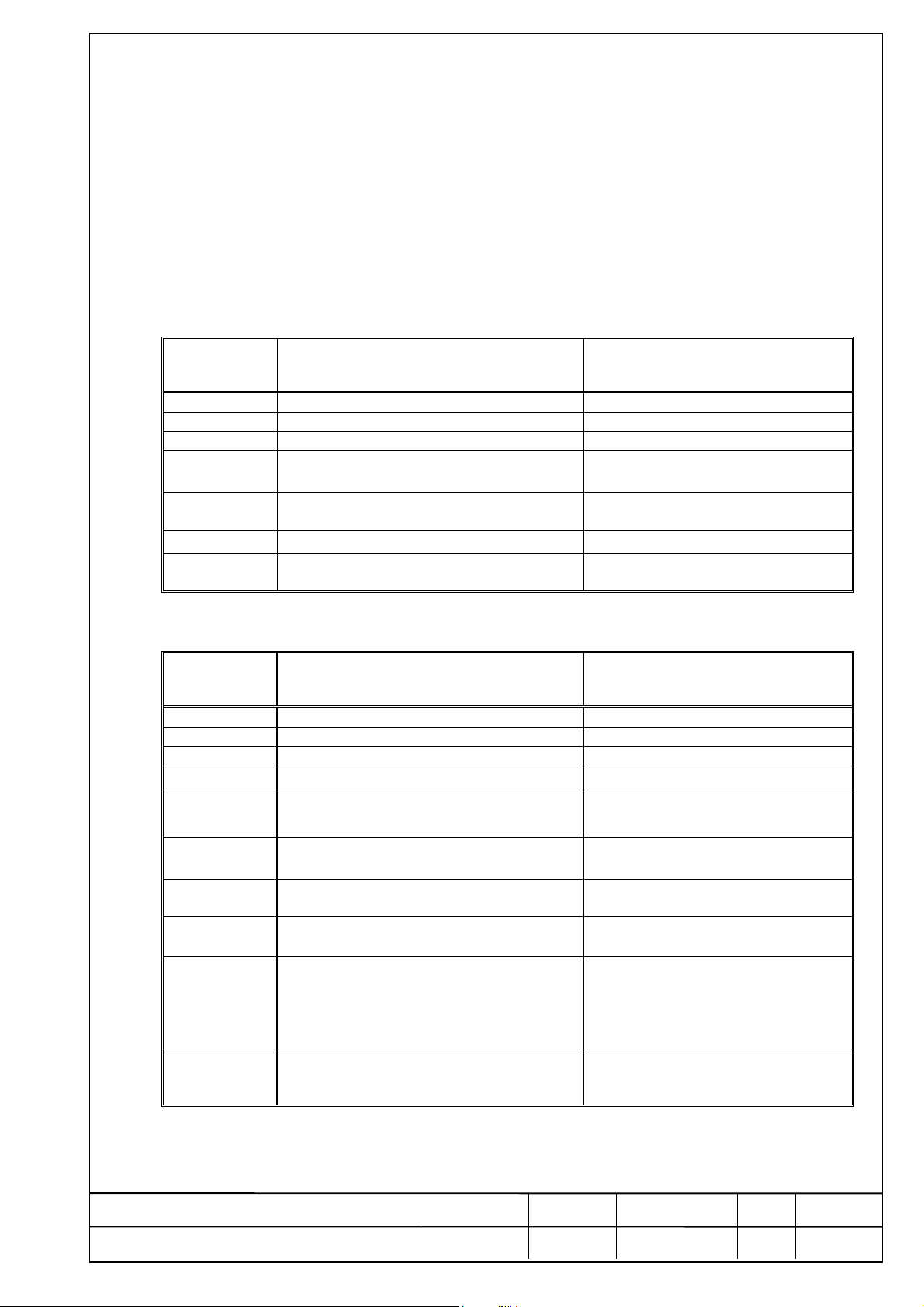
7. ERRORS
If an error occurs d uring the operation, it will be d isplayed in the form Err xx , where xx is the Error
code. Program is halted. Press O momentarily to acknowledge the error and proceed as ind icated in
the
error operator response. Errors may occur during set-up, programming, power-up and during operation.
FAD-4 ERRORS
ERROR
DISPLAY
Err 01 SYSTEM ROM : Faulty ROM Contact manufacturer
Err 02 DATA RAM : Faulty RAM Contact manufacturer
Err 04 CALIBRATION DATA : Faulty EEPROM Recalibrate or contact manufacturer
Err 05 SCALE or A/D CONVERTER Check scale, loadcell cables, contact
Err 15 System has been initialized due to power
ERR90 During span calibration weight is not enough Recalibrate
ERR91 During calibration procedure calibration lock
FDT ERRORS *=Version B only
ERROR
DISPLAY
E 01 SY STEM ROM : Faulty ROM Co nt act manufacturer
E 02 DATA RAM : Faulty RAM Contact manufacture r
E 04 CALIBRATION DATA : Faulty EEPROM Recalibrate or contact manufacturer
* E 16 SYSTEM DATE – T I ME WRONG Enter new date – time.
* E 20 PRINTER IS NOT ON LINE
E 30 COMMUNICATION ERROR Check connections and communication
E 33 PROTOCOL NOT ACK
E 67 CORRUPTED TOTALISER
E 69 TOTALISER OVERFLOW
* E 77 CORRUPTED ALIBI MEMORY
POSSIBLE CAUSE
failure or soft reset.
jumper is inserted.
POSSIBLE CAUSE
OR CALIBRATION LOCK
LOCATION
FLINTEC
ACTION TO BE TAKEN
manufacturers
Zero scale
ACTION TO BE TAKEN
Check printer, cables. Press P to retry
or ` to abort.
parameters
Check connections and communication
parameters
After clearing the error the totaliser is
reset to O
Print / clear totalisers.
Overflow is not critical, but remember
that 1 total capacity must be added to
the indication, each time an overflow
occurs.
The weighing memory can not b e
cleared but next records will be
corrected.
To exit from error display press O .
Document
FDT – VERSION A/B – TECH. -REFERENCE MANUAL
Date
05.04.99
FDT.RM
Code
Rev.
Page
2
of 23
18
Page 19

FLINTEC
8. COMMUNICATIONS
Version A has one communication port RS485A (SERIAL PORT 1). This is the port used for
connection to FAD(s) and for networking.
Version B has in addition to serial port 1 an RS232C port (SERIAL PORT 2), used for connection
with printers or personal computers.
8.1 SERIAL PORT 1 (RS485A)
The port operates in half duplex mode. Communication is based on “LESIP” master / slave serial
interface protocol. (See “LESIP” with FAD appen dix for details).
Baudrate and databits are configured in FDT setup 3.
Cable connections are shown in Annex A “CONNECTOR & CABLE DIAGRAM”.
8.2 SERIAL PORT 2 (RS232C , VERSION B ONLY)
The port operates if full duplex mode. Baudrate is fixed at 1200 bits/sec. 7 data bits, even parity or
8 data bits n o parity may be selected in FDT SE T UP 2.d. The fu nctionality of the port is
also programmed in set up 2. The different modes of operation are detailed below:
8.2.1 CONTINUOUS WEIGHT OUTPUT
The indicated weight and status information is transmitted continu ously. No handshake is required.
Data is output from Pin 3 = Tx and Pin 5 = GND
SET UP REQUIREMENTS (1200, E, 7, 1)
1 Don’t care
2 2.t = 02, 2.d = 17 the rest don’t care
3 According to application
DATA BLOCK COMPOSITION ( P +123.45 CR )
DESCRIPTION
Bit0 0=NORMAL 1=NO WEIGHT DISPLAY
Bit1 0=GROSS 1=NET
SYNC
Bit2 0= 1=AUTO ZERO
Bit3 0=WITHIN RANGE 1=OUT OF RANGE
Bit4 0=NO STANDSTILL 1=STANDSTILL
Bit5 0=NORMAL 1=UNDER MIN. WEIGHING RANGE
Bit6 ALWAYS 1 TO OBTAIN PRINTABLE CHARACTERS
Bit7 ZERO OR PARITY
"+" OR "-"
6 DIGITS DEPENDING ON D 500 N SET UP
INCLUDING DECIMAL POINT IF ANY
CR (0d hex) FOR SYNCHRONISATION
BYTE
1
2
3-8
9
NAME
WEIGHT
STATUS
POLARITY
WEIGHT
DIGITS
Document
FDT – VERSION A/B – TECH. -REFERENCE MANUAL
Date
05.04.99
FDT.RM
Code
Rev.
Page
2
of 23
19
Page 20

FLINTEC
8.2.2 PRINTER OUTPUT
The weight and date time may be printed on.
A serial printer connected with DTR protocol (See Annex A for connection details).
Several print p ossibilities maybe selected in FDT SETUP 2. In addition two custom print formats may
be created and downloaded to the FDT via the serial interface RS232. (Refer to function menu,
chapter 6, Fn 41, Fn 42).
SET UP REQUIREMENTS
1 Application specific
2 2.t = 01 (Date, time, number, weight)
or 2.t = 05 (Gross, Tare, Net, quadruple size)
or 2.t = 06 (Single line Nr, Gross, Tare, N et)
or 2.t = 20 (Custom format 1 in Gross mode, Custom format 2 in Net mode)
3 3.t = 02 or 04 The rest are application specific.
Standard formats may be displaced on the paper by selection of formatting parameters in set up 2.
Parameter 2.3 in set up 2 may be selected to inhibit printing weights below min.
Parameter 2.6 in set up 2 may be selected to inhibit further printouts until the scale weight falls below
min in order to avoid double printing and / or totalising.
Printed weigh ts may be totalized if set up 1.1 = 1.
Parameter 2.7 in set up 2 enables a paper out or printer error to be detected.
Printing is initiated by key P provided that the weight is stable positive and within weighing range.
8.2.3 HOST COMPUTER MODE
This mode is used to communicate with a Host computer. The Host transmits a command and the
FDT replies with the required data or executes the command.
SET UP REQUIREMENTS (1200, E, 7, 1, A)
1 Application specific
2 2t = 09, 2d = 17, 2E = (A-Z)
3 3t = 02 or 04. The rest are application specific.
For approved installations the “ALIBI MEMORY” must be active (set up 1.2).
The following commands have been implemented.
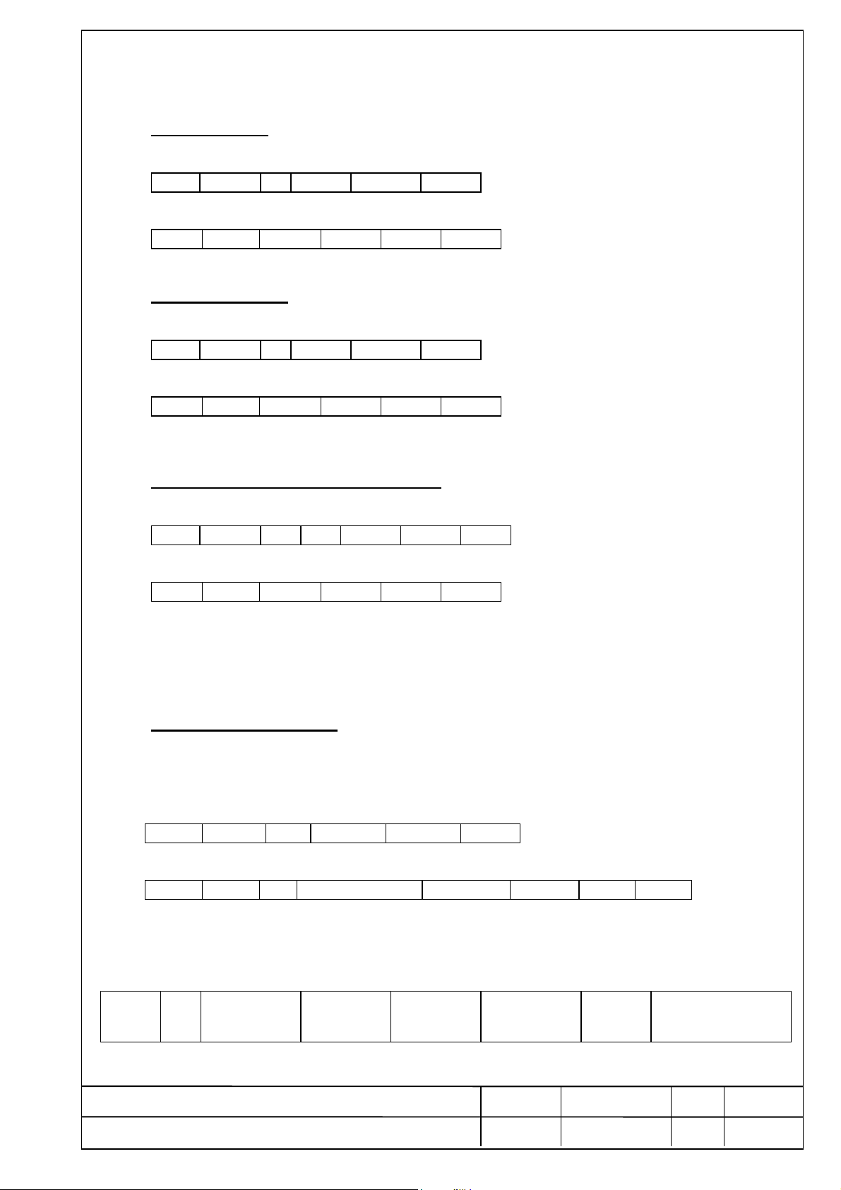
A . SCALE A
Select scale A in a multi scale network.
Master transmission:
STX ADD A BCS2 BCS1 ETX
FDT response:
STX ADD ACK BCS2 BCS1 ETX
Document
FDT – VERSION A/B – TECH. -REFERENCE MANUAL
Date
05.04.99
FDT.RM
Code
Rev.
Page
2
of 23
20
Page 21
FLINTEC
B . SCALE B
Select scale B in a multi scale network.
Master transmission:
STX ADD B BCS2 BCS1 ETX
FDT response:
STX ADD ACK BCS2 BCS1 ETX
C . SCALE A+B
The sum of the weights on scales A and B is returned.
Master transmission:
STX ADD C BCS2 BCS1 ETX
FDT response:
STX ADD ACK BCS2 BCS1 ETX
F . FORMAT CUSTOM DOWNLOAD
The commands is used to download cu stom print formats to FDT.
Master tran smission: where 1=format1
STX ADD F 1 BCS2 BCS1 ETX
FDT response:
STX ADD ACK BCS2 BCS1 ETX
To indicate th at it is ready to receive a continuous string.
When ACK block from the FDT is received the master should start transmittion of the string.
The FDT remains in the receive mode until P is pressed on the keyboard.
No characters exceeding the full length (512b)will be received.
? UPLOAD WEIGHT
Returns the current displayed weight plus status or with a message if bit0 of status b yte is ‘1’.
In the normal state the FDT will respon d within 3-4 character times.
(e.g. With 9600baud, the character time ≈ 1 msec, the master should expect reception of STX
from the FDT within 5 msec after the ETX was transmitted from the master).
Master transmission
STX ADD ? BCS2 BCS1 ETX
FDT response
STX ADD ? STATUS BYTE x x x x x x BCS2 BCS1 ETX
where ? is replaced in scale A,B mode. 1=scale A, 2=scale B, 0=A+B
and xxxxxx = Weight if bo of status byte is zero , or Message if bo of status byte is one.
STATUS BYTE
b7 b6 b5 B4 b3 b2 b1 b0
Zero or
Parity
1 Sign of weight
0=+ 1=-
No Motion
0=NO,
1=YES
Out of range
0=NO
1=YES
Autozero
0=NO
1=YES
0=Gross
1=Net
0=Normal Weight
1=No Weight Display
Document
FDT – VERSION A/B – TECH. -REFERENCE MANUAL
Date
05.04.99
FDT.RM
Code
Rev.
Page
2
of 23
21
Page 22
FLINTEC
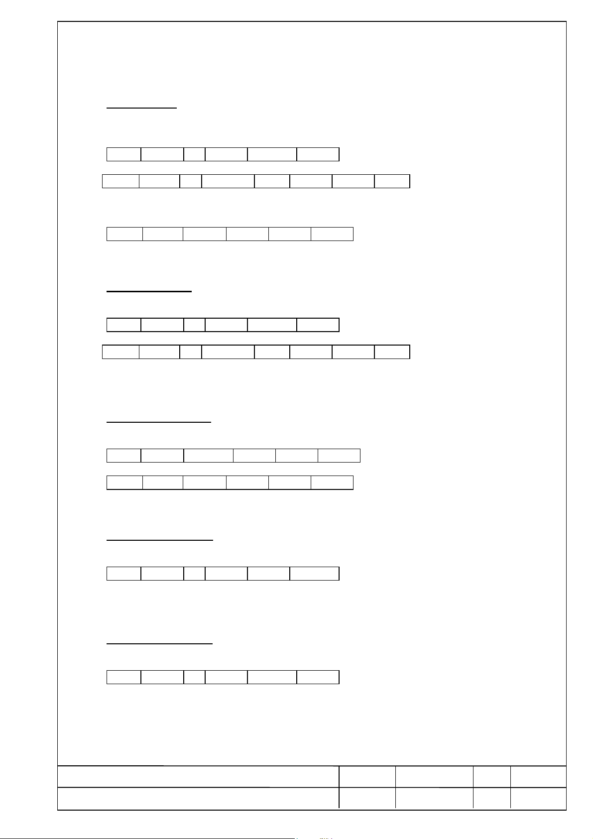
P . PRINT
The scale weight is p rinted in the internal electronic tally roll.
The command returns the weight and sequence number of the Alibi memory.
Master transmission:
STX ADD P BCS2 BCS1 ETX
FDT response:
STX ADD P yyyyyy xxxx BCS2 BCS1 ETX
If printing was succesful where xxxx = 4 digit serial number and
yyyyyy: 6 digits wei ght including decimal point or ------ (empty) or ****** (corrupted data).
or FDT response:
STX ADD NACK BCS2 BCS1 ETX
If print conditions were not met (Motion, -ve weight etc).
R . REPRINT
Returns the last weight and sequence number stored in the Alibi memory.
Master transmission:
STX ADD R BCS2 BCS1 ETX
FDT response:
STX ADD R yyyyyy xxxx BCS2 BCS1 ETX
yyyyyy: 6 digits wei ght including decimal point or ------ (empty) or ****** (corrupted data).
xxxx: 4 digits serial number.
S . SELECT FAD
Selects one of the scales in a multi scale network.
Master transmission: XX= FAD address
STX ADD S XX BCS2 BCS1 ETX
FDT response:
STX ADD ACK BCS2 BCS1 ETX
Err 30 will b e displayed if the FAD address is not programmed for p olling by the FDT (set up 3).
T. TARE/GROSS
Tares the weight on the scale and switches the FAD-4 to net weight mode.
Master transmission:
STX ADD T BCS2 BCS1 ETX
FDT response: NONE.
Execution of the command should be checked by examinin g the next status string.
Z . ZERO SCALE
Sets the scale to zero, if the weight is stable and within 2% of scale capacity .
Master transmission:
STX ADD Z BCS2 BCS1 ETX
FDT response: NONE.
Execution of the command should be checked by examinin g the next status string.
Document
FDT – VERSION A/B – TECH. -REFERENCE MANUAL
Date
05.04.99
FDT.RM
Code
Rev.
Page
2
of 23
22
Page 23

FLINTEC
9. SPECIFICATIONS
9.1. Environmental And Electrical Considerations
AMBIENT TEMPERATURE Storage - 10 oC to + 70 oC. Operating - 10 oC to + 40 oC
No direct sunlight to fall on th e equipment.
HUMIDITY 40% to 90% RH (non condensing)
AIR The surrounding air should be dust free and not contain any
corrosive gases or materials which could adversely affect the
equipment.
VIBRATION Severe vibration can affect the accuracy of weighing and damage
electric / electronic components.
PROTECTION IP 40 for front panel.
ELECTROMAG NETIC / Heavy electrical equipment should not be installed close to
FIELDS the weighing equipment.
POWER SUPPLY 7.5 - 10 VAC 50 Hz or 6 – 12 VDC. Consumption 1,8 Wmax.
INCOMING AND/ Relays and contactors connected to the equipment must have
OUTGOING SIGNALS reliable and effective interference suppression.
Cabling must be performed according to normal practice.
NOTES WELDING on or in the vicinity of weighing equipment is prohibited.
STATIC loads, caused by thunderstorms, must be prevented
from developing by use of reliable lightning conductors.
ENSURE that the cooling of the equipment is not obstructed.
9.2. Technical Specifications
DIGITAL PART VERSION A MCU 89C55, 20K ROM, 64W serial EEPROM.
VERSION B MCU 89C55, 20K ROM, 64W serial EEPROM, 32K
serial FLASH, battery backed real time clock and totalising
RAM.
SELF DIAGNOSTICS Hardware and Software, MCU watchdog.
Memory failure.I/O failure.Program check.
COMMUNICATIONS Serial port RS232C FULL DUPLEX.(1200 baud) (Version B)
Serial port RS485A HALF DUPLEX. (2400-115.000 baud).
DISPLAY 6 digit LED plus annunciators for NET, NO MOTION,
TARE, SP1, SP2. Colour red. Height 14 mm.
KEYBOARD 6 key membrane type.
ALIBI MEMORY Capacity 10.000 records. Cyclic overflow (FIFO).
Display an print operations. Checksum for each record.
EMC COMPATIBILITY Meets or Exceeds EN 45 501 requirements.
DIMENSIONS / PANEL 144 (L) x 72 (H) x 70 (D) / 450 gr.
WEIGHT INOX 180 (L) x 108 (H) x 60 (D) / 1,2 kg.
9.3 MAINTENANCE
The unit does not require any routine maintenance. It may be necessary to perform periodic checks
of the calibration of the scale due to mechanical reasons. The frequency of the calibration checks
depends on the application condition and on the required measuring accuracy.
It may happen that, in exceptional con ditions, the unit locks on a wrong memory location and it is not
possible to restart because the keyboard is not op erative.
To restart it is necessary to switch the power OFF then ON again.
9.4. SERVICE
There are no serviceable parts. The unit may be repaired by trained personnel only.
The user may check cable connection(s) and power supply.
Document
FDT – VERSION A/B – TECH. -REFERENCE MANUAL
Date
05.04.99
FDT.RM
Code
Rev.
Page
2
of 23
23
 Loading...