

Page 1
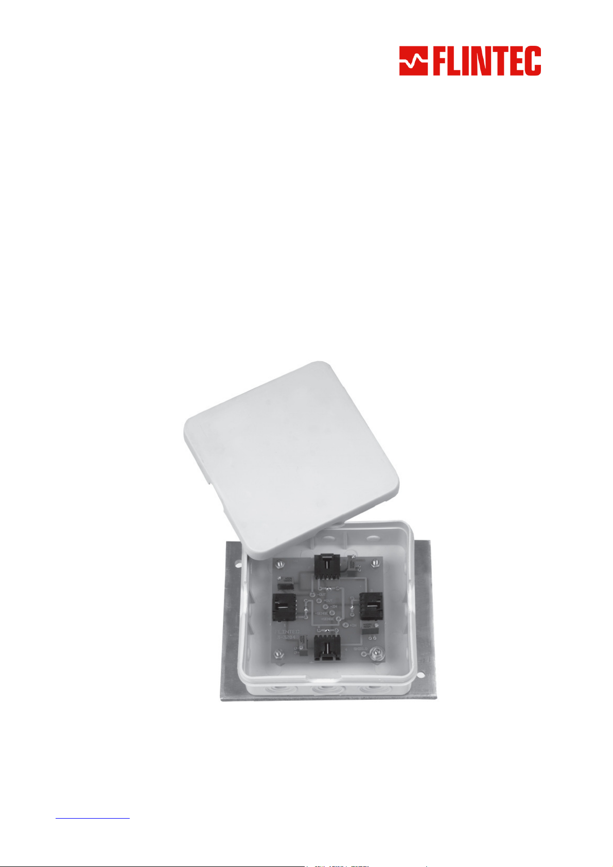
Junction Box
Type KPB-4
T
EECCHHNNIICCAALL
T
M
AANNUUAAL
M
L
Flintec GmbH
Bemannsbruch 9
74909 Meckesheim
GERMANY
www.flintec.com
Page 2
RIGHTS AND LIABILITIES
All rights reserved.
No part of this publication may be reproduced, stored in a retrieval system, or transmitted in any form or by
any means, mechanical, photocopying, recording, or otherwise, without the prior written permission of Flintec
GmbH
No patent liability is assumed with respect to the use of the information contained herein. While every
precaution has been taken in the preparation of this book, FLINTEC assumes no responsibility for errors or
omissions. Neither is any liability assumed for damages resulting from the use of the information contained
herein.
The information herein is believed to be both accurate and reliable. FLINTEC, however, would be obliged to
be informed if any errors occur. FLINTEC cannot accept any liability for direct or indirect damages resulting
from the use of this manual.
FLINTEC reserves the right to revise this manual and alter its content without notification at any time.
Neither FLINTEC nor its affiliates shall be liable to the purchaser of this product or third parties for damages,
losses, costs, or expenses incurred by purchaser or third parties as a result of: accident, misuse, or abuse of
this product or unauthorized modifications, repairs, or alterations to this product, or failure to strictly comply
with FLINTEC operating and maintenance instructions.
FLINTEC shall not be liable against any damages or problems arising from the use of any options or any
consumable products other than those designated as Original FLINTEC Products.
NOTICE: The contents of this manual are subject to change without notice.
Copyright © 2007 by Flintec GmbH, 74909 Meckesheim, Bemannsbruch 9, Germany
S
AFETY INSTRUCTIONS
CAUTION READ this manual BEFORE operating or servicing this equipment. FOLLOW
these instructions carefully. SAVE this manual for future reference. DO NOT allow untrained
personnel to operate, clean, inspect, maintain, service, or tamper with this equipment.
ALWAYS DISCONNECT this equipment from the power source before cleaning or performing
maintenance. CALL FLINTEC ENGINEERING for parts, information, and service.
WARNING ONLY PERMIT QUALIFIED PERSONNEL TO SERVICE THIS EQUIPMENT.
EXERCISE CARE WHEN MAKING CHECKS, TESTS AND ADJUSTMENTS THAT MUST BE
MADE WITH POWER ON. FAILING TO OBSERVE THESE PRECAUTIONS CAN RESULT
IN BODILY HARM.
WARNING FOR CONTINUED PROTECTION AGAINST SHOCK HAZARD CONNECT
TO PROPERLY GROUNDED OUTLET ONLY. DO NOT REMOVE THE GROUND PRONG.
WARNING DISCONNECT ALL POWER TO THIS UNIT BEFORE REMOVING THE
FUSE OR SERVICING.
WARNING BEFORE CONNECTING/DISCONNECTING ANY INTERNAL ELECTRONIC
COMPONENTS OR INTERCONNECTING WIRING BETWEEN ELECTRONIC EQUIPMENT
ALWAYS REMOVE POWER AND WAIT AT LEAST THIRTY (30) SECONDS BEFORE ANY
CONNECTIONS OR DISCONNECTIONS ARE MADE. FAILURE TO OBSERVE THESE
PRECAUTIONS COULD RESULT IN DAMAGE TO OR DESTRUCTION OF THE
EQUIPMENT OR BODILY HARM.
CAUTION OBSERVE PRECAUTIONS FOR HANDLING ELECTROSTATIC SENSITIVE
DEVICES.
Junction Box Type KPB-4 – Technical Manual, Rev. 1.00 September 2007
Page 2 of 4
Page 3
I
NTRODUCTION AND TECHNICAL DATA
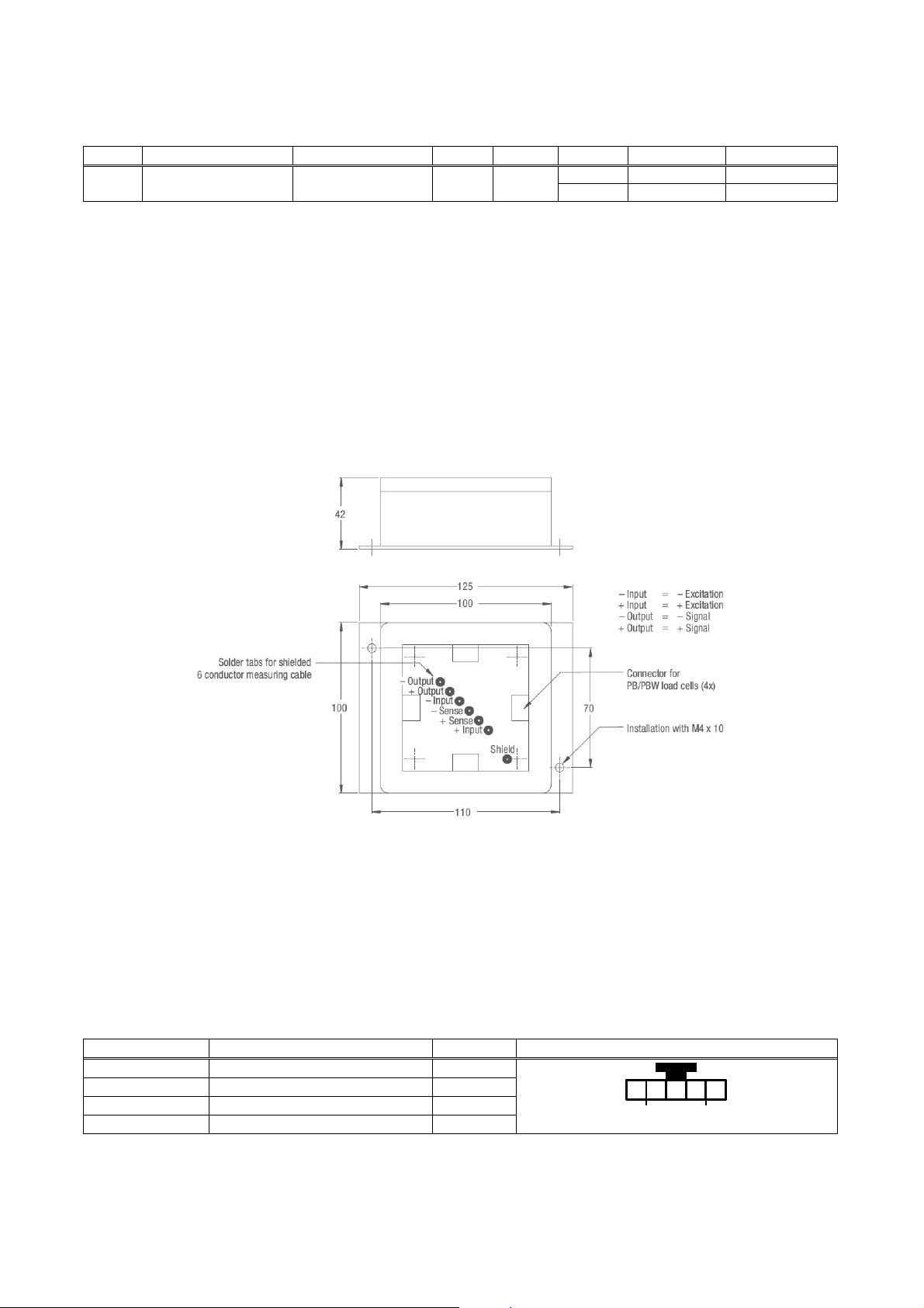
The plastic junction box is designed for the parallel connection of 4 load cells type PB or type PBW.
There are 2 versions available.
Type No. of load cells Housing size Inputs Output Vers. Potentiom. Accuracy cl.
KPB-4 up to 4x type PB/PBW 100 x 100 x 40 mm 4 1
The junction box type KPB-4 can be connected to the instrumentation with a shielded 6-wire signal cable.
The corner correction is done with potentiometer.
Housing material: Plastic
Protection class: IP54
Cable connection: Load cell cable with plug connector AMP #103957-4; output cable by soldering
Corner correction: By potentiometer
M
ECHANICAL INSTALLATION
Look for a mounting location which is more or less dry and protected from environmental stress.
Before you mount the junction box you should prepare (drill) a holl for the output cable.
E
LECTRICAL CONNECTIONS
1 10 Ω
2 50 Ω
C3
GP
Figure 1: Dimensions in [mm]
The connection sequence of the load cells should correspond to the corners of the scale, i.e
Corner 1 = Load cell 1, Corner 2 = Load cell 2, etc.
L
OAD CELL CABLE CONNECTION
Connect the load cell cable with its plug connector to the prepared plug connector on the printed circuit board.
Afterwards prepare the load cell cable with the delivered cable sleeve, so that later on the cable inlet gets tight
and the plug connector stress relieved.
The load cell cable connections at the AMP- plug are as follows:
Cable coulour Description Pin no. Plug connector load cell cable (top view)
red = Signal – (Output –) 5
white = Signal + (Output +) 4
black = Excitation – (Input –) 2
green = Excitation + (Input +) 1
Junction Box Type KPB-4 – Technical Manual, Rev. 1.00 September 2007
1 2 4 51 2 4 51 2 4 51 2 4 5
Page 3 of 4
Page 4
O
UTPUT CABLE CONNECTION
The signal cable (connection between junction box and the following electronics) should be a 6 – wire
shielded cable and has to be kept as short as possible. It will be pulled through a cable inlet which has to be
prepared at site.
Then feed the tin-plated wires through the hole at the solder point. Use a suitable soldering iron for electronic
works (at least 30 Watt ). Proper solder joints always look bright and shiny.
Never use soldering solution and soldering grease! This will destroy the printed circuit board!
Always use suitable electronic solder, e.g. S-Sn60Pb40 DIN EN 29453.
Depending on type and manufacturer signal cables may have different colours. Therefore make your own
choice.
Cable colour, example Description / Terminal designation
outer cable screen = Shield
pink = Out – (Signal –)
white = Out + (Signal +)
grey = Sense –
brown = In – (Excitation –)
yellow = Sense +
green = In + (Excitation +)
C
ORNER CORRECTION AT SCALES WITH FLINTEC LOAD CELLS
Flintec load cells are manufactured with rather tight tolerances, so in most cases an additional corner
correction is not required. The best conditions are achieved if you use load cells of the same class
(Designation is done with capital letters A to I on the load cell package besides the type label).
Hint: Corner errors can have a mechanical background, e.g. sloped mounting surface of the load cell.
Procedure:
1. The jumpers JP1 to JP4 besides the potentiometer should stay installed. This will disable the
potentiometers (shipment status).
2. Get the display value for each corner. Use the highest possible display resolution (e.g. factor 10 or higher)
or, if this is not possible, measure the the digital weight increment using corresponding weights.
3. The corner with the lowest display value is the starting point for the corner correction. The differences of
the other corners are calculated with reference to this “basic corner”.
4. Calculate the correction resistance as follows:
Correction resistance [Ω] =
* 1100 Ω input resistance for:
400 Ω input resistance for:
Example 1: 1100 Ω load cell
0.1 kg corner error with 500 kg test load
Example 2: 400 Ω load cell
10 kg corner error with 5000 kg test load
5. The calculated correction resistance is used as the starting point when the correction is made with the
potentiometers P1 to P4 (25 turns; version 1: 10 Ohm Cermet- precision trimmer; version 2: 50 Ohm
trimmer). When shipped all potentiometers are in the middle position (appr. 5 Ohm) and disabled by the
jumpers JP1 to JP4 (short-circuit). If a potentiometer shall be enabled, the corresponding jumper JPx has
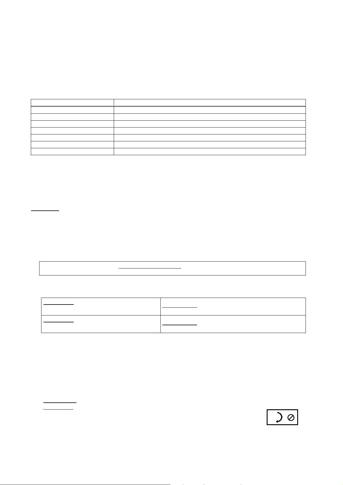
to be removed. First you have to turn the potentiometer to the clockwise end position (clicking noise).
Afterwards you turn the potentiometer counterclockwise until the computed correction resistance is
adjusted.
6. Check the corners again. If required repeat the procedure.
Hints for Poti
adjustment:
Finally install the cover of the box.
• Use suitable screwdriver !
• Version 1: One turn corresponds to appr. 0.4 Ohm
Version 2: One turn corresponds to appr. 2 Ohm
• Clockwise end position = 0 Ohm
• Version 1: Counterclockwise end position = 10 Ohm
Version 2: Counterclockwise end position = 50 Ohm
• Jumpers besides the enabled potentiometers must stay removed
Deviation in [kg]
Test load in [kg]
BK2, SB4, SB5, SB6, SB14, SLB, ZLB, UB1, UB5, UB6, PB, RC3
RC1, SB2
X Input resistance of the load cell [Ω] *
0.1 kg
500 kg
10 kg
5000 kg
x
x
1100 ΩΩΩΩ
400 ΩΩΩΩ
=
0.22 Ω
=
0.8 Ω
Junction Box Type KPB-4 – Technical Manual, Rev. 1.00 September 2007
Page 4 of 4
 Loading...