

Page 1
Reg No 4-8721 Rev1
Date: 2006-12-27. Sign: KN
Application Guidelines
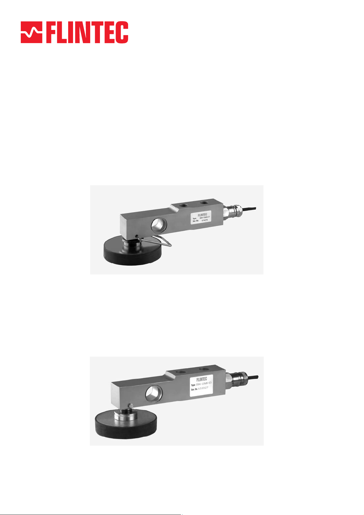
Rubber Foot
Type 52-02
Height Adjustable Rubber Foot
Type 52-10, 52-15
Page 2
Basic function
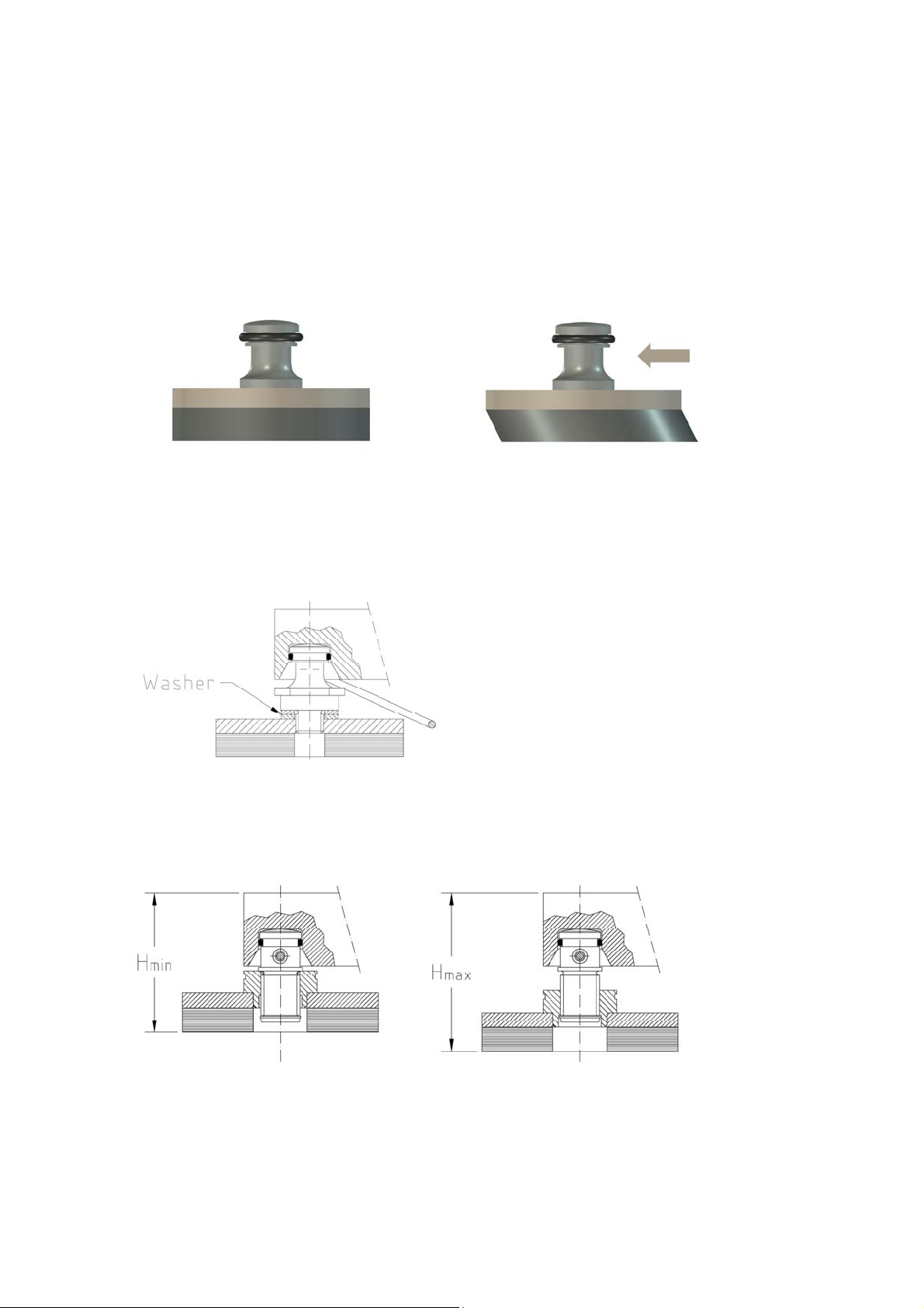
The basic function of the rubber element is to prevent side forces from affecting
load cell performance and at the same time, keeping the load carrier in position.
The rubber element is not to be seen as a vibration damper although is has a
limited damping effect.
It is relatively stiff in vertical direction while weak in horizontal direction.
No side force = centred Side force acting
Height Adjustment
For Type 52-02 the
height can be
adjusted by adding
standard washers
between the loading
pin and the rubber
foot. See Figure 1.
Figure 1
For Type 52-10 (and 52-15) the height is adjusted by simply rotating the rubber
foot. The loading pin is prevented from rotation with the foot by the retaining
screw. See Figure 2.
Figure 2
2
Page 3
Retaining Function
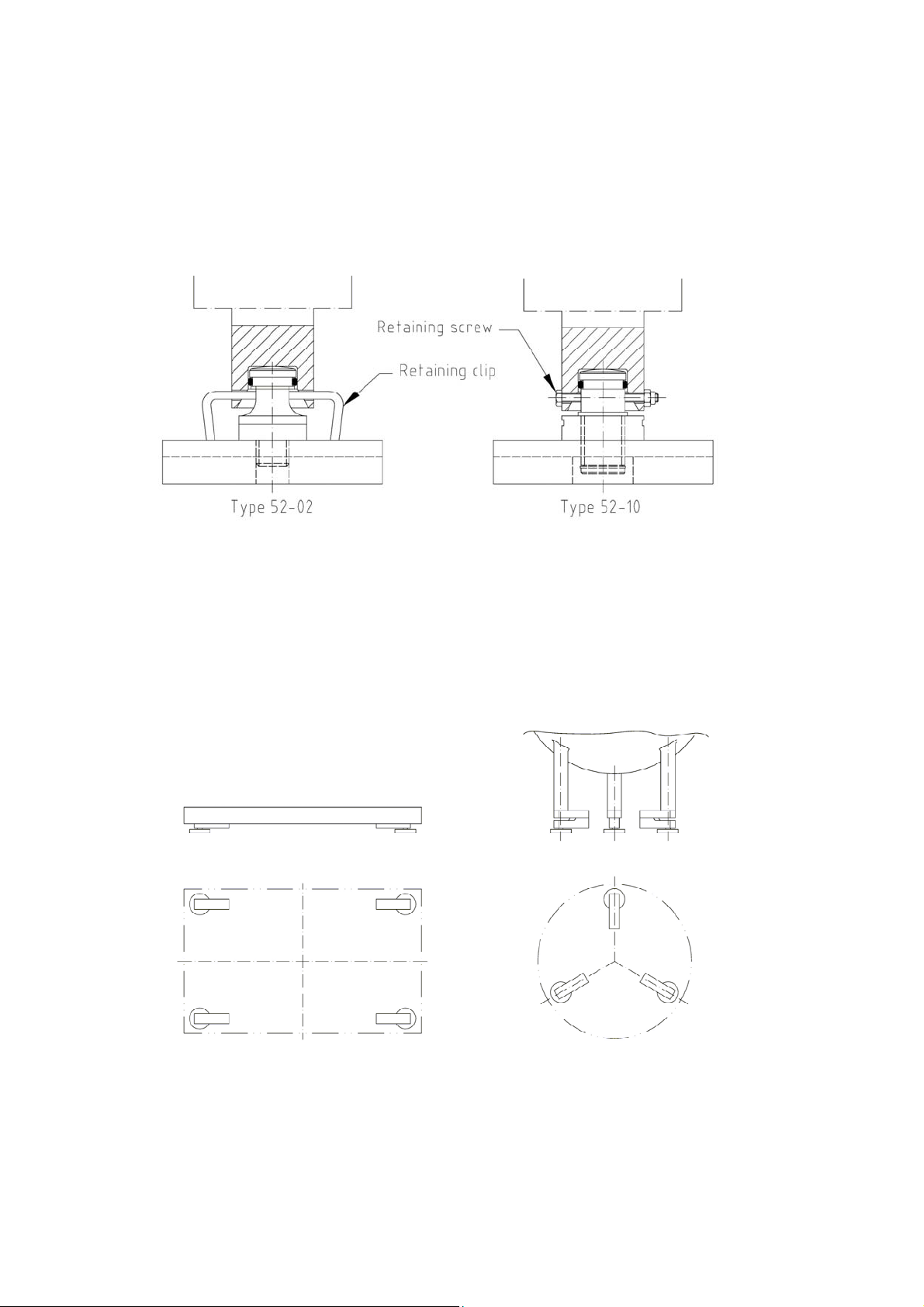
For type 52-02 a spring clip prevents the rubber foot from falling out in case the
load carrier is lifted. For Type 52-10 a screw through the cell and loading pin gives
the same function. See Figure 3.
Figure 3
Installation examples
The Load Cells should be positioned so that the load is distributed as equally as
possible between them. See examples below.
Installation under weigh platform Installation under tank
Figure 4
3
Page 4
Installation examples
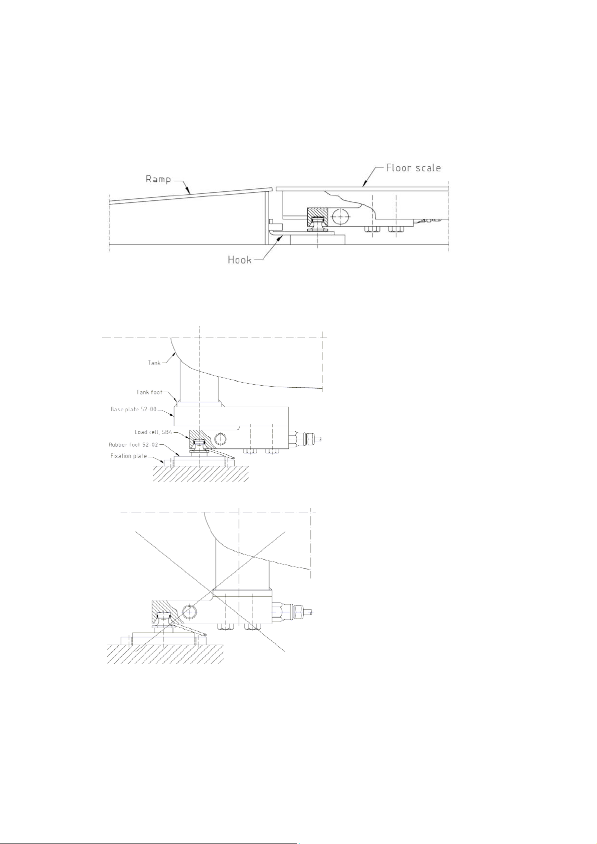
Figure 5 shows the rubber foot Type 52-02 installed under a floor scale. A hook is
mounted on the loading pin, holding the ramp in position.
Figure 5
Figure 6 shows the
Rubber Foot Type 5202 installed, under a
tank together with Base
Plate 52-00. Fixation
plates keep the Rubber
Feet in position on the
floor, in case of
vibrating load carriers
or when there is risk for
Figure 6
load carrier being
pushed out of position.
Figure 7
4
Figure 7 shows
incorrect mounting
which gives a bending
moment in the tank leg.
The rubber foot shall be
positioned on the
centreline of the leg,
see Figure 6.
Page 5
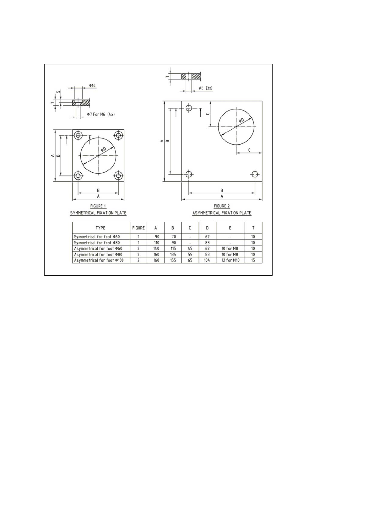
Fixation plates
Figure 8
Normally 2 fixation plates are sufficient, positioned at the 2 load cells which are
furthest apart in the scale. The fixation plates shall be well centred to the rubber
feet. One practical method to achieve centring is to push all fixation plates in same
direction, in contact with the rubber elements and with the plates in this position,
For the symmetrical fixation plates:
Carefully mark the position of the fixation plate with sharp pen marks on the
floor or use small pieces of tape positioned close to the fixation plate. Lift away the
load carrier and drill holes as required for the fixation screws, using the fixation
plate as a template. Finally reposition the load carrier.
For the asymmetrical fixation plates:
In this case the holes can be drilled without lifting the load carrier, because
the fixation plate extends outside the load carrier. Just make sure the fixation
plates do not move while drilling the holes. For fixation with plugs, drill with same
diameter as the holes to get centre marks. Then rotate the plate 45° and drill the
larger holes for the plugs.
5
Page 6
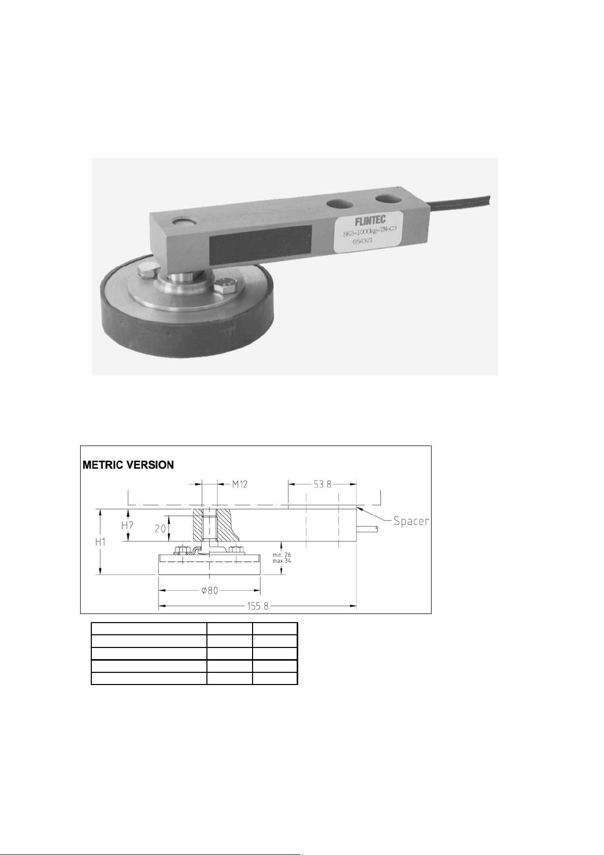
Type 52-15, Height Adjustable Rubber Foot
The Height Adjustable Rubber Foot is also available as Type 52-15. This version
is designed for the BK2 Load Cells. It is available in both metric (M12) and unified
(1/2”-20UNF) versions. See Figure 9.
Dimensions and data, Type 52-15 (Metric)
Load Cell Type H1 H2
BK2-200 kg 38,7...46,7 12,7
BK2-500 kg 41,9...49,9 15,9
BK2-1000 kg 45,1...53,1 19,1
BK2-2000 kg 51,4...59,4 25,4
All dimensions in mm. Dimensions and specifications are subject to change without notice.
CAD files for customer’s own applications drawings are available on request.
Figure 9
6
Page 7
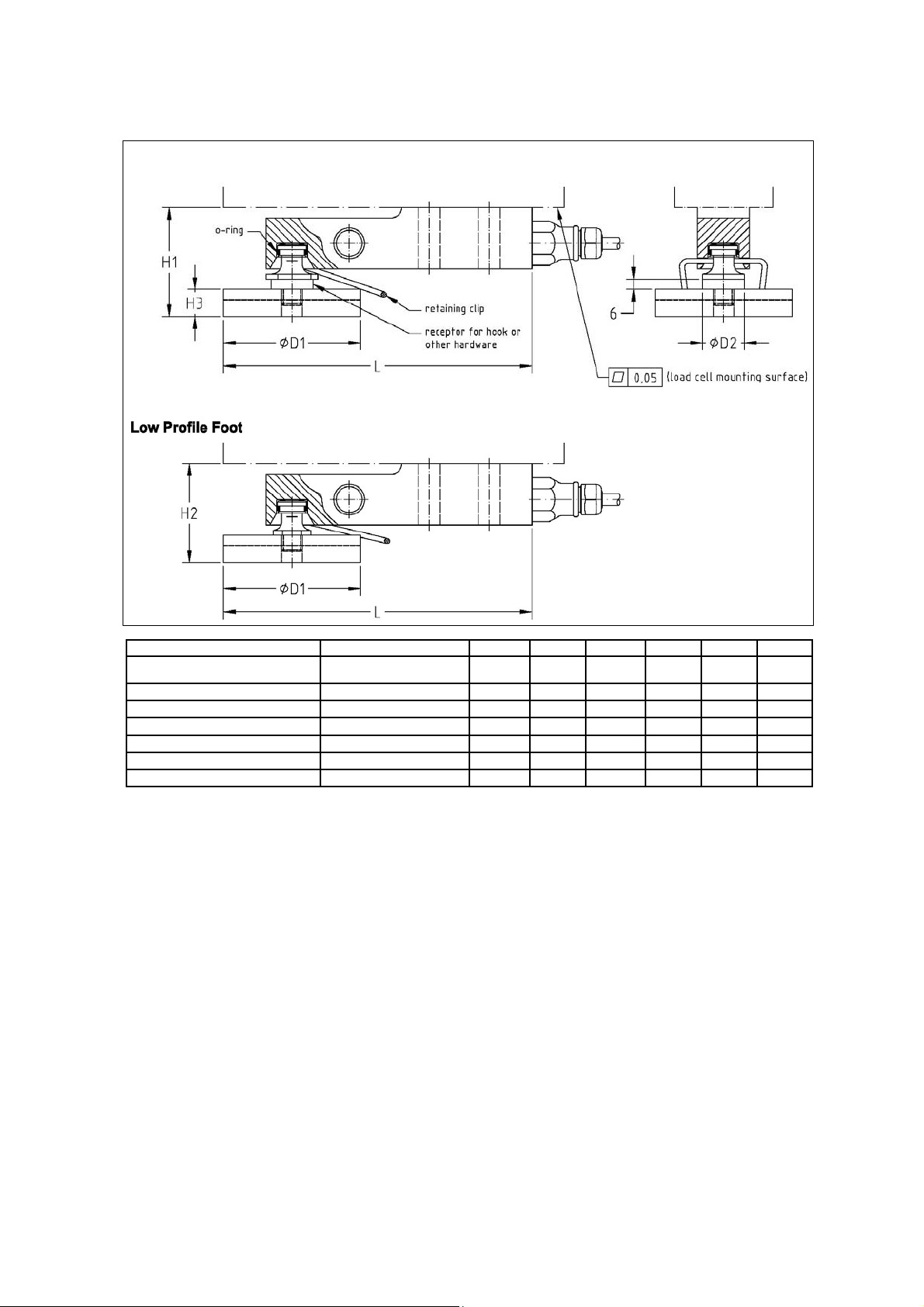
Dimensions and data, Type 52-02
Load Cell Type Capacity in kg L H1 H2 H3 D1 D2
SB4/SB5-5 kN/10 kN/20 kN 510/1020/2039 180 65 58 16 80 24.5
SB4/SB5-50 kN 5099 219 90 n.a. 18 100 34.5
SB4/SB5-100 kN 10179 278 109 n.a. 26 125 44
SB14-500 lb/1 klb 227/454 164 60 53 16 80 24.5
SB14-2.5 klb/5 klb 1134/2268 164 62* 55* 16 80 24.5
SLB-200 lb/500 lb 91/227 154 61* 54* 16 60 24.5
SLB-1 klb/2.5 klb/5 klb 454/1134/2268 164 61* 54* 16 80 24.5
* Including spacer.
** A special retaining clip is available
All dimensions in mm. Dimensions and specifications are subject to change without notice.
CAD files for customer’s own applications drawings are available on request.
7
Page 8
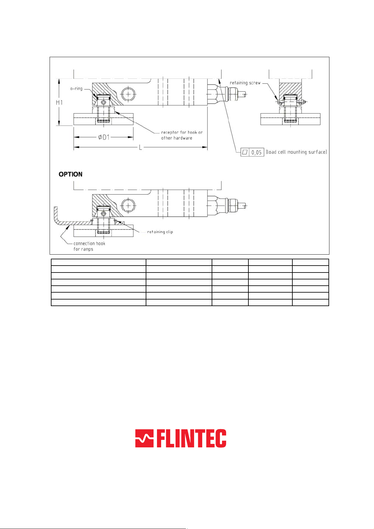
Dimensions and data, Type 52-10
Load Cell Type Capacity in kg L H D
SB4/SB5-5 kN/10 kN/20 kN 510/1020/2039 180 63...71 80
SB6-200 N/500 N/1 kN/2 kN 20.4/51/102/204 150 65...71* 60
SB14-500 lb/1 klb 227/454 164 58...66 80
SB14-2.5 klb/5 klb 1134/2268 164 60...68* 80
SLB-200 lb/500 lb 91/227 154 57...63* 60
SLB-1 klb/2.5 klb/5 klb 454/1134/2268 164 59...67* 80
* Including spacer.
All dimensions in mm. Dimensions and specifications are subject to change without notice.
CAD files for customer’s own applications drawings are available on request.
www.flintec.com
 Loading...