

Page 1
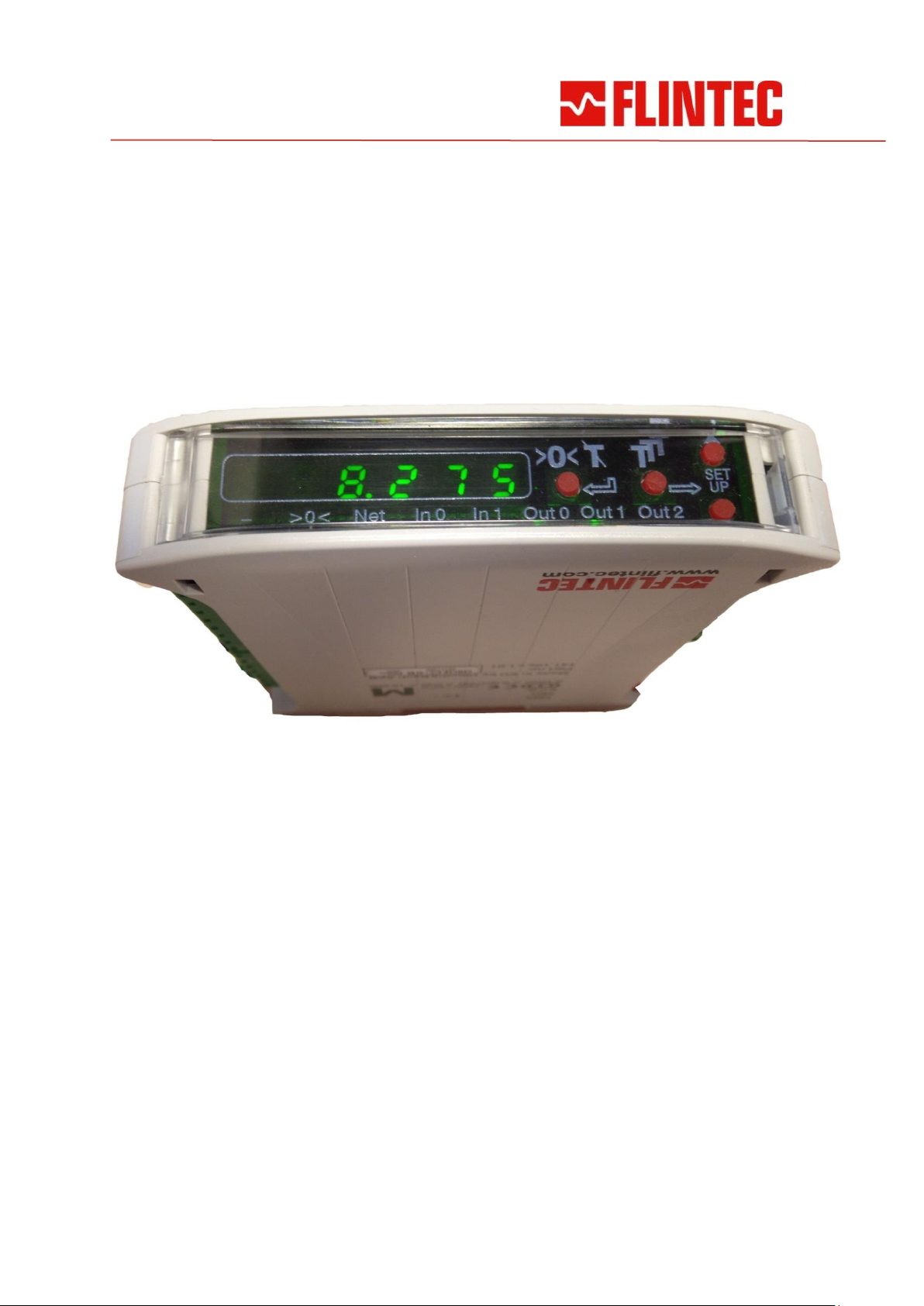
Type DAD 141.1
Technical Manual Modbus Communication
Firmware Version 141.181.v.1.06 or higher
Hardware Version 141.10x.v.1.01
Document No. E223-1 Rev. 2.2 EN
DAD 141.1 Technical Manual Modbus Communication, Rev. 2.3 - Juni 2014 Page 1
Page 2

1. How to use Modbus in DAD 141.1
1.1. Implemented functions for Modbus RTU and Modbus TCP.
0x03 Read holding registers: Used for reading 16 or 32bit values.
0x04 Read input registers: Same as above.
0x06 Write single register: Used for writing 16bit values.
0x10 Write multiple registers: Used for writing 32bit values.
1.2. Modbus RTU
The baudrate must be set in menu 8.1.
In multidrop or 2 wire applications the user must select "485" in menu 8.2 or "422" for
point to point 4 wire applications.
A Modbus address between 1 and 247 must be set in menu 8.3.
The parity used in the actual Modbus network must be selected in menu 8.7
(select no or o = odd or e = even).
The Modbus RTU mode must be selected in menu 8.8 (select RTU).
1.3. Modbus Protocols
1.3.1. Modbus RTU via Serial Port
binary data protocol
1.3.2. Modbus TCP via Ethernet Port:
binary data protocol, embedded in TCP/IP packages
Modbus TCP port: 502
IP address is 192.168.0.100 (factory default)
1.4. Modbus Index Tables
See the following pages.
DAD 141.1 Technical Manual Modbus Communication, Rev. 2.3 - Juni 2014 Page 2
Page 3

Index (hex)
Type
Size
Access
Function
2000
Float
2 R Gross Weight
This Index returns the latest Gross value obtained from a DAD141.
The format is IEEE754 Single precision floating point format. The 32 bit data is obtained by reading 2
16-bit registers from index 2000.
The Gross Weight are also sent when reading multiple DAD141 data at index 3500.
see also command description: GG get gros value
2002
Float
2 R Net Weight
This Index returns the latest Netto value obtained from a DAD141.
The format is IEEE754 Single precision floating point format. The 32 bit data is obtained by reading 2
16-bit registers from index 2002.
The Netto Weight are also sent when reading multiple DAD141 data at index 3500.
see also command description: GN get net value
2008
Float
2 R Average Weight
This Index returns the latest average weight value obtained from a DAD141.
The format is IEEE754 Single precision floating point format. The 32 bit data is obtained by reading 2
16-bit registers from index 2008.
see also command description: GA get average value
2020
Int32
2 R Gross Weight
This Index returns the Gross weight value obtained from a DAD141.
The 32 bit integer data is obtained by reading 2 16-bit registers from index 2020.
The Gross Weight are also sent when reading multiple DAD141 data at index 3300.
see also command description: GG get gros value
2022
Int32
2 R Net Weight
This Index returns the Netto weight value obtained from a DAD141.
The 32 bit integer data is obtained by reading 2 16-bit registers from index 2022.
The Netto Weight are also sent when reading multiple DAD141 data at index 3300.
see also command description: GN get net value
2028
Int32
2 R Average Weight
This Index returns the latest average weight value obtained from a DAD141.
The 32 bit integer data is obtained by reading 2 16-bit registers from index 2028.
see also command description: GA get average value
202A
Int32
2 R A/D Sample
This Index returns the current ADC value obtained from a DAD141.
The 32 bit integer data is obtained by reading 2 16-bit registers from index 202A.
see also command description: GS get sample
202C
Int32
2 R Device ID
This Index returns the current ID of a DAD141.
The 32 bit integer data is obtained by reading 2 16-bit registers from index 202C.
The the high word (202C) are 0(zero) and the low word (202D) should be split into two bytes:
1. Byte is the minor ID, normally 10h (16d).
2. Byte is the major ID, normally 14h (20d).
see also command description: ID identification device
DAD 141.1 Technical Manual Modbus Communication, Rev. 2.3 - Juni 2014 Page 3
Page 4

Index (hex)
Type
Size
Access
Function
Description
202E
Int32
2 R Firmware
Version
This Index returns the current Firmware version of a DAD141.
The 32 bit integer data is obtained by reading 2 16-bit registers from index 202E.
The the high word (202E) are 0 (zero) and the low word (202F) should be split into two bytes:
1. Byte is the minor IV, e.g. 02h (02d).
2. Byte is the major IV, e.g. 17h (23d).
see also command description: IV Firmware Version
2030
Int32
2 R Device Status
This Index returns the current Status for a DAD141.
The 32 bit integer data is obtained by reading 2 16-bit registers from index 2030.
see also command description: IS Device Status
2034
Int32
2 R Serial Number
This Index returns the serial number of the DAD141.
The 32 bit integer data is obtained by reading 2 16-bit registers from index 2034.
see also command description: RS Read Serial Number
2060
Int16
1 R Qualifier
This Index returns the latest Qualifier value obtained from a DAD141.
The 16 bit integer data is obtained by reading one 16-bit registers at index 2060.
The Qualifier bit values are:
0001h - Under range
0002h - Over range
0010h - No motion, still stand, steady state
0020h - Tare set
0100h - Set-point 0 (source>limit)
0200h - Set-point 1
0400h - Set-point 2
The Qualifier word are also sent when reading multiple DAD141 data at index 3300 or 3500.
2061
Int16
1 W Bit Commands
This Index is used to set or reset Zero, Tare or Max / Valley / Peak2Peak.
The 16 bit integer data is accessed by writing one 16-bit register at index 2061.
see also command description:
01h: RZ Reset Zero
02h: SZ Set Zero
04h: RT Reset Tare
08h: ST Set Tare
10h: RM Reset Max
20h: TH Trigger Hold
2062
Int16
1 W Trigger
This Index is used to trigger measurements in the DAD 141.1.
The 16 bit integer data is accessed by writing one 16-bit register at index 2062.
The value 0080h starts the triggered measurement.
see also command description: TR Software Trigger
Index (hex)
Type
Size
Access
Function
Description
2066
Int16
1 W Save in
This Index is used to Initiate writing to the DAD141 EEPROM.
DAD 141.1 Technical Manual Modbus Communication, Rev. 2.3 - Juni 2014 Page 4
Page 5

EEPROM
The 16 bit integer data is accessed by writing one 16-bit register at index 2066.The values are:
0001h: AS Save analog parameters
0002h: CS Save calibration
0004h: WP Save general setup parameters
0010h: SS Save set-point parameters
8000h: FD Factory default
2067
Int16
1
RW
SetPoint
Selection
This Index is used to select Setpoint in a DAD141.
The 16 bit integer data is accessed by writing one 16-bit register at index 2067.
The values are 0 (zero) to 2 and selects the setpoint acted upon by indexes:
2068h,206Ah, 206Ch and 2070h.
This index act as the ‘n‘ parameter for the A’n‘, H’n‘, S’n‘ and P’n‘ commands
see also command description: A‘n‘ Assign action, H‘n‘ Hysteresis, S‘n‘ Setpoint, P‘n‘ Polarity
2068
Int32
2
RW
SetPoint Source
This Index is used to select Setpoint Source in a DAD141.
The 32 bit integer data accessed by reading or writing 2 16-bit registers from index 2068.
0 = Gross weight as setpoint source
1 = Net weight as setpoint source
2 = Peak value (Max) as setpoint source
3 = Average value as setpoint source
4 = Hold value as setpoint source
5 = Peak to Peak value as setpoint source
6 = Valley value (Min.) as setpoint source
7 = Error 4 or 5 as setpoint source
see also command description: A’n‘ (n = 0, 1, 2, 3, 4, 5, 6, 7, 8)
206A
Int32
2
RW
SetPoint
Hysteresis
This Index is used to get or set Setpoint Hysteresis in a DAD141.
The 32 bit integer data accessed by reading or writing 2 16-bit registers from index 206A.
see also command description: H’n‘ (n = 0, 1, 2)
206C
Int32
2
RW
SetPoint Value
This Index is used to get or set Setpoint limit in a DAD141.
The 32 bit integer data accessed by reading or writing 2 16-bit registers from index 206C.
see also command description: S’n‘ (n = 0, 1, 2)
2070
Int32
2
RW
SetPoint Polarity
This Index is used to get or set Setpoint polaritiy in a DAD141.
The 32 bit integer data accessed by reading or writing 2 16-bit registers from index 2070.
The values of switch logic are 0 or 1.
see also command description: P’n‘ (n = 0, 1, 2)
DAD 141.1 Technical Manual Modbus Communication, Rev. 2.3 - Juni 2014 Page 5
Page 6
Index (hex)
Type
Size
Access
Function
Description
2074
Int16
1
RW
Logic Input
Select
This Index is used to get or set Logic Input Function in a DAD141.
The 32 bit integer data accessed by reading or writing 2 16-bit registers from index 2074.
The values of the function are 0 or 1.
see also command description: AI’n‘, ‘m‘ (n = 0 or 1) Assign Input.
2076
Int16
1
RW
Assign Logic
Input
This Index is used to get or set Logic Input Function in a DAD141.
The 32 bit integer data accessed by reading or writing 2 16-bit registers from index 2074.
The values of the function are 00 to 15.
see also command description: AI’n‘, ‘m‘ (m = 0 … 15) Assign Input
2080
Float
2 R Peak Value
This Index returns the latest peak value obtained from a DAD141.
The format is IEEE754 Single precision floating point format. The 32 bit data is obtained by reading 2
16-bit registers from index 2080. See also command description: GM Get Peak Value
2082
Int32
2 R Peak Value
This Index returns the peak value of the DAD141.
The 32 bit integer data is obtained by reading 2 16-bit registers from index 2082.
see also command description: GM Get Peak Value
2084
Float
2 R Hold
This Index returns the latest hold value obtained from a DAD141.
The format is IEEE754 Single precision floating point format. The 32 bit data is obtained by reading 2
16-bit registers from index 2084. See also command description: GH Get Hold Value
2086
Int32
2 R Hold
This Index returns the hold value of the DAD141.
The 32 bit integer data is obtained by reading 2 16-bit registers from index 2086.
see also command description: GH Get Hold Value
2088
Float
2 R Valley Value
This Index returns the latest valley value obtained from a DAD141.
The format is IEEE754 Single precision floating point format. The 32 bit data is obtained by reading 2
16-bit registers from index 2088. See also command description: GV Get Valley Value
208A
Int32
2 R Valley Value
This Index returns the valley value of the DAD141.
The 32 bit integer data is obtained by reading 2 16-bit registers from index 208A.
see also command description: GV Get Valley Value
208C
Float
2 R Peak to Peak
Value
This Index returns the latest valley value obtained from a DAD141.
The format is IEEE754 Single precision floating point format. The 32 bit data is obtained by reading 2
16-bit registers from index 208C. See also command description: GO Get Peak Value
208E
Int32
2 R Peak to Peak
Value
This Index returns the peak value of the DAD141.
The 32 bit integer data is obtained by reading 2 16-bit registers from index 208E.
see also command description: GO Get Peak Value
2100
Int32
2
RW
Analog Action
This Index is used to select Analog Output Source.
The 32 bit integer data accessed by reading or writing 2 16-bit registers from index 2100.
The values of the analog action are 0 to 8.
see also command description: AA Analog output source
Index (hex)
Type
Size
Access
Function
Description
DAD 141.1 Technical Manual Modbus Communication, Rev. 2.3 - Juni 2014 Page 6
Page 7
2102
Int32
2
RW
Analog High
This Index defines the weight value for the high analog output.
The 32 bit integer data accessed by reading or writing 2 16-bit registers from index 2102.
see also command description: AH Analog High
2104
Int32
2
RW
Analog Low
This Index defines the weight value for the low analog output.
The 32 bit integer data accessed by reading or writing 2 16-bit registers from index 2104.
see also command description: AL Analog Low
2106
Int32
2
RW
Filter Setting
This Index is used to select the filter setting.
The 32 bit integer data accessed by reading or writing 2 16-bit registers from index 2106.
The values of the low pass filters are 0 to 7.
see also command description: FL Filter Value
210A
Int32
2
RW
Logic Output
This Index Reads/Modify the status of the physical output signals.
The 32 bit integer data accessed by reading or writing 2 16-bit registers from index 210A.
see also command description: IO Status of the logic Output
210C
Int32
2 R Logic Input
This Index reads the status of the physical input signals.
The 32 bit integer data accessed by reading or writing 2 16-bit registers from index 210C.
see also command description: IN Read status of logic Input
210E
Int32
2
RW
Measuring Time
See index 2410
2110
Int32
2
RW
Filter Mode
This Index chooses the filter mode, permitted values are “0” for IIR and “1” for FIR.
The 32 bit integer data accessed by reading or writing 2 16-bit registers from index 2110.
see also command description: FM Filter Mode
2112
Int32
2
RW
No Motion
Range
This Index Reads/Modify the maximum number of counts allowed as no motion.
The 32 bit integer data accessed by reading or writing 2 16-bit registers from index 2112.
see also command description: NR No Motion Range
2114
Int32
2
RW
No Motion Time
This Index Reads/Modify the minimum time the weight must stay within NR to be no motion.
The 32 bit integer data accessed by reading or writing 2 16-bit registers from index 2114.
see also command description: NT No MotionTime
2116
Int32
2
RW
Logic Output
Mask
This Index Reads/Modify the mask of the logic Outputs.
The 32 bit integer data accessed by reading or writing 2 16-bit registers from index 2116.
see also command description: OM Control of logic Outputs
2118
Int32
2 R Tare Value
This Index Reads the Tare value.
The 32 bit integer data accessed by reading 2 16-bit registers from index 2118.
see also command description: GT Get tare value
211A
Int32
2
RW
Start Delay
See index 2412
211C
Int32
2
RW
Trigger Edge
See index 2402
211E
Int32
2
RW
Trigger Level
See index 2400
Index (hex)
Type
Size
Access
Function
Description
2120
Int32
2
RW
Update Rate
This Index chooses Average after the filter by 2 exp. UR samples.
The 32 bit integer data accessed by reading or writing 2 16-bit registers from index 2120.
DAD 141.1 Technical Manual Modbus Communication, Rev. 2.3 - Juni 2014 Page 7
Page 8
The values of the update rate are 0 to 7 (2 exp 0 = 1, 2 exp 7 = 128).
see also command description: UR Update Rate
2122
Int32
2
RW
Zero Tracking
This Index enables or disables the zero tracking (TAC protected).
The 32 bit integer data accessed by reading or writing 2 16-bit registers from index 2122.
The values of Zero Tracking function are 0 to 255.
see also command description: ZT Zero Tracking
2128
Int32
2
RW
Analog Output
Mode
This Index is used for set the analog output mode.
The 32 bit integer data accessed by reading or writing 2 16-bit registers from index 2128.
The values of the output mode are 0 to 5
see also command description: AM Analog Output Mode
2200
Int32
2
RW
Absolute Gain
Calibration
This Index Reads/Modify the absolute gain point (TAC protected).
The 32 bit integer data accessed by reading or writing 2 16-bit registers from index 2200.
see also command description: AG Absolute Gain
2202
Int32
2
RW
Absolute Zero
Calibration
This Index Reads/Modify the absolute zero point (TAC protected).
The 32 bit integer data accessed by reading or writing 2 16-bit registers from index 2202.
see also command description: AZ Absolute Zero
2204
Int32
2
RW
Calibrate Enable
This Index sets the calibration functions to the enabled state.
The 32 bit integer data accessed by reading or writing 2 16-bit registers from index 2204.
see also command description: CE Calibrate Enable
2206
Int32
2
RW
Calibrate Gain
This Index sets the calibration gain (span) value (TAC protected).
The 32 bit integer data accessed by reading or writing 2 16-bit registers from index 2206.
see also command description: CG Calibrate Gain
220C
Int32
2
RW
Calibrate Max
This Index Reads/Modify the maximum allowable output value (TAC protected).
The 32 bit integer data accessed by reading or writing 2 16-bit registers from index 220C.
see also command description: CM Maximum Output
220E
Int32
2
RW
Calibrate Min
This Index Reads/Modify the minimum allowable output value (TAC protected).
The 32 bit integer data accessed by reading or writing 2 16-bit registers from index 220E.
see also command description: CI Minimum Output
2212
Int32
2 W Calibrate Zero
This Index sets the calibration zero point (TAC protected).
The 32 bit integer data accessed by writing 2 16-bit registers from index 2212.
see also command description: CZ Calibrate Zero
2214
Int32
2
RW
Decimal Point
This Index Reads/Modify the decimal point position (TAC protected).
The 32 bit integer data accessed by reading or writing 2 16-bit registers from index 2214.
see also command description: DP Decimal Point
Index (hex)
Type
Size
Access
Function
Description
2216
Int32
2
RW
Display Step
Size
This Index Reads/Modify the the display step size (TAC protected).
The 32 bit integer data accessed by reading or writing 2 16-bit registers from index 2216.
see also command description: DS Display Step Size
DAD 141.1 Technical Manual Modbus Communication, Rev. 2.3 - Juni 2014 Page 8
Page 9
221E
Int32
2
RW
Initial Zero
@ Power ON
This Index enables or disables the initial zero function @ power ON.
The 32 bit integer data accessed by reading or writing 2 16-bit registers from index 221E.
see also command description: ZI Initial Zero ON/OFF
2220
Int32
2
RW
Zero Range
This Index selects the zero range.
The 32 bit integer data accessed by reading or writing 2 16-bit registers from index 221E.
A value of 0 enables the standard zero range of ± 2% of maximum.
see also command description: ZR Zero Range
2224
Int32
2
RW
Store Tare value
@ Power OFF
This Index enables or disables the tare storing in EEPROM @ power OFF.
The 32 bit integer data accessed by reading or writing 2 16-bit registers from index 2224.
see also command description: TN Store Zero Value
2226
Int32
2
RW
Store Zero Value
@ Power OFF
This Index enables or disables the zero storing inh EEPROM @ power OFF.
The 32 bit integer data accessed by reading or writing 2 16-bit registers from index 2226.
see also command description: ZN Store Zero Value
2400
Int32
2
RW
Trigger Level
This Index selects the trigger level.
The 32 bit integer data accessed by reading or writing 2 16-bit registers from index 2400.
see also command description: TL Trigger Level
2402
Int32
2
RW
Trigger Egde
This Index selects rising or falling slope trigger.
The 32 bit integer data accessed by reading or writing 2 16-bit registers from index 2402.
see also command description: TE Trigger Edge
2408
Int32
2
RW
Hold Time
This Index Reads/Modify the Hold time of setpoint S0.
The 32 bit integer data accessed by reading or writing 2 16-bit registers from index 2408.
see also command description: HT Hold Time
240A
Int32
2
RW
Tare Window
This Index Reads/Modify the tare window.
The 32 bit integer data accessed by reading or writing 2 16-bit registers from index 240A.
see also command description: TW Tare Window
240C
Int32
2
RW
Tare Time
This Index Reads/Modify the tare time.
The 32 bit integer data accessed by reading or writing 2 16-bit registers from index 240C.
see also command description: TI Tare Time
2410
Int32
2
RW
Measuring Time
This Index Reads/Modify the time over which the average value will be built.
The 32 bit integer data accessed by reading or writing 2 16-bit registers from index 2410.
see also command description: MT Measure Time
DAD 141.1 Technical Manual Modbus Communication, Rev. 2.3 - Juni 2014 Page 9
Page 10
Index (hex)
Type
Size
Access
Function
Description
2412
Int32
2
RW
Start Delay
This Index Reads/Modify the delay between falling/rising edge of the trigger pulse and start of the
measurement. The 32 bit integer data accessed by reading or writing 2 16-bit registers from index
2412.
see also command description: SD Start Delay
3006
Int32
2 R MAC Hi
This Index reads the four most significant bytes of the MAC address.
The 32 bit integer data accessed by reading 2 16-bit registers from index 3006.
3008
Int32
2 R MAC Lo
This Index reads the two least significant bytes of the MAC address.
The 32 bit integer data accessed by reading 2 16-bit registers from index 3008.
300C
Int32
2
RW
IP Address
This Index reads/Modify the IP Address. A change will take effect after reset.
The 32 bit integer data accessed by reading or writing 2 16-bit registers from index 300C.
see also command description: NA Network Address
3300
Int32
Int32
Int16
5 R Combined
result, integer
This index reads the gross weight, the net weight and the qualifier.
The 32 bit integer data accessed by reading or writing 2 16-bit registers from index 3300.
see also command description: GW Get data string “net, gross and status“
3500
Float
Float
Int16
5 R Combined
result, floating
point
This index reads the gross weight, the net weight and the qualifier.
The 32 bit integer data accessed by reading or writing 2 16-bit registers from index 3500.
see also command description: GW Get data string “net, gross and status“
DAD 141.1 Technical Manual Modbus Communication, Rev. 2.3 - Juni 2014 Page 10
 Loading...