

Page 1
m
b
Y
e
T
e
m
e
C
U
N
s
6
n
t
8
M
8
1
n
&
A
A
G
8
.
Load
ell Digi
izing U
it
yp
LD
TECH
U 6
ICAL
.1
NU
6
L
.2
Fir
ware Ver
Hardwar
Flintec G
Bemanns
74909 Me
GERMAN
www.flint
bH
ruch 9
ckesheim
c.com
Version
Docume
ion 68.1
8.101.5.v
t No. G1
1.v.4.00 o
.3.00 & 68
9 Rev12
higher
.201.5 v.3
B
.00
Page 2

Table of Contents:
1. Safety Instructions .................................................................................................................................... 4
2. Declaration of Conformity ........................................................................................................................ 5
3. Introduction and Specifications ............................................................................................................... 6
4. Communications and Getting started ..................................................................................................... 7
4.1. Serial Interface ......................................................................................................................................... 7
4.2. Command Language ................................................................................................................................ 7
4.3. Baud Rate / Device Address .................................................................................................................... 8
4.4. Getting Started ......................................................................................................................................... 8
5. Hardware and Wiring ................................................................................................................................. 9
5.1. Wiring ....................................................................................................................................................... 9
5.2. With Unit Adapter UA 77.1 (RS232) ........................................................................................................ 9
5.3. With Unit Adapter UA 73.2 (RS422 / RS485 Full-/Half-Duplex) .............................................................. 9
5.4. Terminal Configuration ........................................................................................................................... 10
5.5. Load Cell Connection ............................................................................................................................. 10
6. Calibration and Calibration Sequence ................................................................................................... 11
7. Commands – Overview ........................................................................................................................... 12
8. Commands Description .......................................................................................................................... 13
8.1. System Diagnosis Commands – ID, IV, IS, SR, RS .............................................................................. 13
8.1.1. ID Get Device Identity ................................................................................................................................... 13
8.1.2. IV Get Firmware Version ............................................................................................................................... 13
8.1.3. IS Get Device Status ..................................................................................................................................... 13
8.1.4. SR Reset LDU XX.X Firmware ...................................................................................................................... 13
8.1.5. RS Read Serial Number ................................................................................................................................ 13
8.2. Calibration Commands – CE, CM, DS, DP, CZ, CG, ZT, ZI, FD, CS .................................................... 14
8.2.1. CE Read TAC* Counter / Open Calibration Sequence ................................................................................. 14
8.2.2. CM Set Maximum Output Value ..................................................................................................................... 14
8.2.3. DS Set Display Step Size .............................................................................................................................. 14
8.2.4. DP Set Decimal Point Position ...................................................................................................................... 14
8.2.5. CZ Set Calibration Zero Point ....................................................................................................................... 14
8.2.6. CG Set Calibration Gain (Span) ..................................................................................................................... 15
8.2.7. ZT Enable / Disable Zero Tracking ................................................................................................................ 15
8.2.8. ZI Initial Zero Range ...................................................................................................................................... 15
8.2.9. FD Reset to Factory Default Settings ............................................................................................................ 15
8.2.10. CS Save the Calibration Data ....................................................................................................................... 15
8.3. Motion Detection Commands – NR, NT ................................................................................................. 16
8.3.1. NR Set No-motion Range ............................................................................................................................... 16
8.3.2. NT Set No-motion Time Period ..................................................................................................................... 16
8.4. Filter Setting Commands – FL, FF, UR .................................................................................................. 17
8.4.1. FL Filter Settings ........................................................................................................................................... 17
8.4.2. FF Moving Average ....................................................................................................................................... 17
8.4.3. UR Update Rate ............................................................................................................................................. 17
8.5. Taring and Zeroing Commands – SZ, RZ, ST, RT ................................................................................ 18
8.5.1. SZ Set Zero ................................................................................................................................................... 18
8.5.2. RZ Reset Zero Point...................................................................................................................................... 18
8.5.3. ST Set Tare ................................................................................................................................................... 18
8.5.4. RT Reset Tare ............................................................................................................................................... 18
8.6. Output Commands – GG, GN, GT, GS, GF, GW, GA ........................................................................... 19
8.6.1. GG Get Gross Value ...................................................................................................................................... 19
8.6.2. GN Get Net Value .......................................................................................................................................... 19
8.6.3. GT Get Tare Value ........................................................................................................................................ 19
8.6.4. GS Get ADC Sample Value ........................................................................................................................... 19
8.6.5. GF Get Filtered Value ................................................................................................................................... 19
8.6.6. GW Get Data String “Net, Gross and Status“ ................................................................................................. 19
8.6.7. GA Get Triggered Average Value .................................................................................................................. 19
LDU 68.1 & 68.2 Technical Manual, Rev. 12 January 2010
Page 2 of 28
Page 3

8.7.
Auto–transmit Commands – SG, SN, SF, SW, SA ................................................................................ 20
8.7.1. SG Send Gross Value continuously ............................................................................................................... 20
8.7.2. SN Send Net Value continuously .................................................................................................................. 20
8.7.3. SF Send Filtered Value continuously (Display Mode only) ............................................................................ 20
8.7.4. SW Send Data String “Net, Gross and Status“ continuously .......................................................................... 20
8.7.5. SA Send Triggered Average Value automatically ......................................................................................... 20
8.8. Commands for External I/O Control – IN, IO, IM ................................................................................... 21
8.8.1. IN Read the Status of the Input Channels ..................................................................................................... 21
8.8.2. IO Read / Set the Status of the Output Channels .......................................................................................... 21
8.8.3. IM Control of the logic outputs by the host application .................................................................................. 21
8.9. Setpoint Output Commands – Sn, Hn, An ............................................................................................. 22
8.9.1. S0 / S1 Setpoint Value ................................................................................................................................... 22
8.9.2. H0 / H1 Setpoint Hysteresis and Switching Action ......................................................................................... 22
8.9.3. A0 / A1 Allocation of Gros or Net Value ......................................................................................................... 22
8.10. Communication Setup Commands – AD, BR, CL, DX, TD, OP ......................................................... 23
8.10.1. AD Device Address ........................................................................................................................................ 23
8.10.2. BR Baud Rate ................................................................................................................................................ 23
8.10.3. CL Close Device Address n .......................................................................................................................... 23
8.10.4. DX Half-duplex or Full-duplex ....................................................................................................................... 23
8.10.5. TD Transmission Delay ................................................................................................................................. 23
8.10.6. OP Open Device ............................................................................................................................................ 23
8.11. Save Calibration and Setup Data Commands – CS, WP, SS, GI, PI ................................................ 24
8.11.1. WP Save the Setup Parameters .................................................................................................................... 24
8.11.2. SS Schaltpunkt-Parameter sichern ............................................................................................................... 24
8.11.3. GI Save an Image File from the EEPROM .................................................................................................... 24
8.11.4. PI Download an Image File to the EEPROM ................................................................................................. 24
8.12. Trigger Commands – SD, MT, GA, TE, TR, TL, SA ........................................................................... 25
8.12.1. SD Start Delay Time...................................................................................................................................... 25
8.12.2. MT Measuring Time ....................................................................................................................................... 25
8.12.3. GA Get Triggered Average Value .................................................................................................................. 25
8.12.4. TE Trigger Edge ............................................................................................................................................ 25
8.12.5. TR Software Trigger ...................................................................................................................................... 25
8.12.6. TL Trigger Level ............................................................................................................................................ 26
8.12.7. SA Send Triggered Average Value automatically ......................................................................................... 26
9. Use in “Approved” Applications (LDU 68.1 only) ................................................................................ 27
10. Updates – Firmware Download .............................................................................................................. 28
LDU 68.1 & 68.2 Technical Manual, Rev. 12 January 2010
Page 3 of 28
Page 4

.
RIGHTS
A
e
t
e
t
I
s
c
o
s
T
©
S
h
L
h
s
n
o
t
o
d
i
o
1
n
a
e
H
A
Y
G
N
A
E
O
O
A
e
r
r
s
t
s
h
d
c
t
o
u
G
h
A
m
s
P
O
O
E
N
E
T
W
S
D
V
n
s
e
f
c
a
a
e
a
n
e
t
e
9
B
n
r
c
n
A
C
P
T
C
W
N
U
e
F
r
a
h
a
a
m
n
e
e
m
c
R
E
R
O
N
O
O
A
M
T
R
e
p
c
s
h
N
e
o
i
s
r
s
f
A
P
T
V
G
Y
U
S
G
m
p
e
s
e
v
c
a
h
d
a
o
e
q
o
n
N
O
A
O
E
R
R
N
S
o
e
o
n
r
o
c
n
O
d
A
M
E
N
N
T
T
R
E
Q
N
f
a
m
f
w
s
t
T
C
O
O
ND LIABI
ITIES
All rights r
No part of
means, m
GmbH
No patent l
precaution
omissions.
herein.
The inform
informed if
the use of
FLINTEC r
Neither FL
losses, co
this produ
FLINTEC
FLINTEC
consumabl
NOTICE:
Copyright
served.
his publicati
chanical, p
iability is as
has been ta
Neither is a
ation herein
any errors
his manual.
eserves the
NTEC nor i
ts, or expen
t or unauth
perating an
hall not be l
e products
he contents
2010-201
on may be r
otocopying,
umed with
ken in the p
y liability a
is believed
ccur. FLINT
right to revi
s affiliates s
ses incurre
rized modifi
maintenan
able agains
ther than th
of this man
by Flintec
produced,
recording, o
espect to th
eparation o
sumed for d
o be both a
EC cannot
e this manu
all be liable
by purchas
ations, rep
e instructio
any damag
se designa
al are subj
mbH, 7490
tored in a r
r otherwise,
use of the
this book,
amages res
curate and
ccept any li
l and alter i
to the purc
r or third p
irs, or alter
ns.
es or proble
ed as Origi
ct to chang
9 Meckeshe
trieval syst
without the
information
LINTEC as
ulting from t
eliable. FLI
bility for dir
ts content w
aser of this
rties as a re
tions to this
s arising fr
al FLINTEC
without not
im, Bemann
m, or trans
rior written
ontained h
umes no re
e use of th
TEC, howe
ct or indire
thout notific
product or t
sult of: acci
product, or f
m the use
Products.
ce.
bruch 9, G
itted in any
permission
rein. While
ponsibility f
informatio
er, would b
t damages
tion at any
ird parties f
ent, misuse
ailure to stri
f any optio
rmany
form or by
f Flintec
very
r errors or
contained
obliged to
esulting fro
time.
r damages,
, or abuse o
tly comply
s or any
ny
be
ith
1.
afety I
CAUTION
instructions
operate, cle
this equipm
ENGINEER
WARNING
EXERCISE
MADE WIT
BODILY H
WARNING
PROPERL
WARNING
SERVICIN
WARNING
COMPONE
LWAYS R
CONNECTI
PRECAUTI
BODILY H
CAUTION
DEVICES.
structi
READ t
carefully. S
n, inspect,
nt from the
ING for part
ONLY
CARE WHE
POWER
RM.
FOR C
GROUND
DISCO
.
BEFOR
TS OR IN
MOVE PO
NS OR DI
NS COUL
RM.
OBSER
ons
is manual
VE this ma
aintain, se
power sour
, informatio
ERMIT QU
N MAKING
N. FAILING
NTINUED
D OUTLET
NECT ALL
CONNEC
ERCONNE
ER AND
CONNECT
RESULT I
E PRECA
EFORE op
ual for futur
rvice, or ta
e before cle
, and servi
LIFIED PE
HECKS, T
TO OBSE
ROTECTI
ONLY. DO
POWER T
ING/DISC
TING WIRI
AIT AT LE
IONS ARE
DAMAGE
TIONS FO
rating or se
e reference.
per with thi
aning or per
e.
SONNEL T
STS AND
VE THESE
N AGAINS
OT REMO
THIS UNIT
NNECTIN
NG BETWE
ST THIRT
ADE. FAIL
O OR DE
HANDLIN
vicing this e
DO NOT all
equipment.
orming mai
SERVICE
DJUSTME
RECAUTI
SHOCK H
E THE GR
BEFORE R
ANY INTE
N ELECT
(30) SECO
RE TO OB
TRUCTION
ELECTRO
quipment. F
ow untraine
ALWAYS D
tenance. C
THIS EQUI
TS THAT
NS CAN R
ZARD CO
UND PRO
MOVING
NAL ELEC
ONIC EQUI
DS BEFO
SERVE TH
OF THE E
STATIC SE
LLOW the
personnel
ISCONNEC
LL FLINTE
PMENT.
UST BE
SULT IN
NECT TO
G.
HE FUSE
RONIC
PMENT
E ANY
SE
UIPMENT
SITIVE
e
o
R
R
LDU 68
.1 & 68.2 Tec
nical Manual
Rev. 12 Ja
uary 2010
Page 4 o
28
Page 5

.
2.
D
0
a
e
h
u
b
p
t
m
n
e
ä
3
t
A
t
t
e
h
n
A
p
E
h
t
/
t
A
:
g
m
e
e
c
i
e
e
i
R
C
K
D
m
t
o
r
1
c
m
n
p
e
a
n
r
h
c
A
A
u
A
r
n
m
m
t
n
o
r
h
t
m
e
s
e
m
e
g
Pr
k
C
/
n
7
u
e
r
ulawcom
r
A
s
i
e
l
d
c
a
in
fe
m
9
h
r
E
8
e
e
e
5/
e
d
e
n
n
a
y
e
m
ro
n
g
v
g
e
O
r
h
O
(
5
e
y
e
a
n
s
2
0
s
f
eclara
ion of
onfor
ity
Mon
Herst
Ansc
Prod
Das
This
Rich
Parla
zur A
Mitgli
Vertr
89/3
Rich
ktbezeichnun
t/Jahr: month
ller: Manufac
rift:
ddress
ezeichnete P
roduct confir
linie 2004/10
ents und de
gleichung d
dstaaten üb
glichkeit und
6/EWG
linie 2006/95
EG-
EC-
year:
urer:
: Product na
rodukt stimm
s with the foll
8/EG des Eu
s Rates vom
r Rechtsvors
r die elektro
zur Aufhebu
/EG Nieders
onfor
eclara
e:
mit folgende
wing regulati
opäischen
5. Dezembe
hriften der
agnetische
g der Richtlin
annungs-Ric
itätser
ion of
Vorschriften
ns of the Dir
2004
ie
tlinie
lärung
onfor
07
2010
Fli
tec GmbH
mannsbruch
Be
4909 Meckes
DDe
tschland / Ge
LD
U 68.1 / LDU
der Europäis
ctives of the
Di
ective 2004/10
Co
ncil of 15th D
s of the Memb
patibility and r
ective 2006/9
Di
it
eim
any
68.2
hen Richtlini
uropean Co
/EC of the Eu
ember 2004 o
r States relatin
pealing Directi
EC Low Volta
en überein:
munit
opean Parliam
n the approxim
to electromag
e 89/336/EEC
e Directive
nt and of the
tion of the
etic
Die
bsicherung al
Quali
ätsmerkmale
Quali
ätsmanagem
Diese
Erklärung bes
den g
nannten Richtl
Zusic
erung von Eig
Folge
de Normen w
s a
roof of conform
OIML
-76-1
DIN
N 45501
ler produktsp
erfolgt auf B
ent-Systems
heinigt die Übe
nien, beinhaltet
nschaften.
rden zum Nac
ty with the dire
Nicht-Selbsttäti
Non-automatic
Metrologische
nhang B.3: F
nhang C: Ve
zifischen
sis eines zer
ach DIN ISO
einstimmung
jedoch keine
weis der Über
tives following
Waagen – M
weighing syste
spekte nichts
nktionsprüfun
fahren für die
ifizierten
9001.
it
instimmung mit
tandards are fu
trologische un
ms – Metrologi
lbsttätiger Wa
en unter Störe
rüfung derStör
sy
Th
dir
ll
product-relat
tem in accor
s declaration c
ctives, but it is
den Richtlinien
filled:
technische A
al and technic
gen; Deutsche
flüssen
stigkeit gegen
d features ar
ance with IS
rtifies the confo
o promise of c
eingehalten:
forderungen (
l requirements
Fassung EN 4
ochfrequente
e assured by
9001.
rmity with the li
aracteristics.
IML R-76:200
(OIML R-76:20
501:1992
lektromagneti
a quality
ted
Teil 1)
2 Part 1)
che Felder.
LDU 68
.1 & 68.2 Tec
nical Manual
Rev. 12 Ja
uary 2010
Page 5 o
28
Page 6
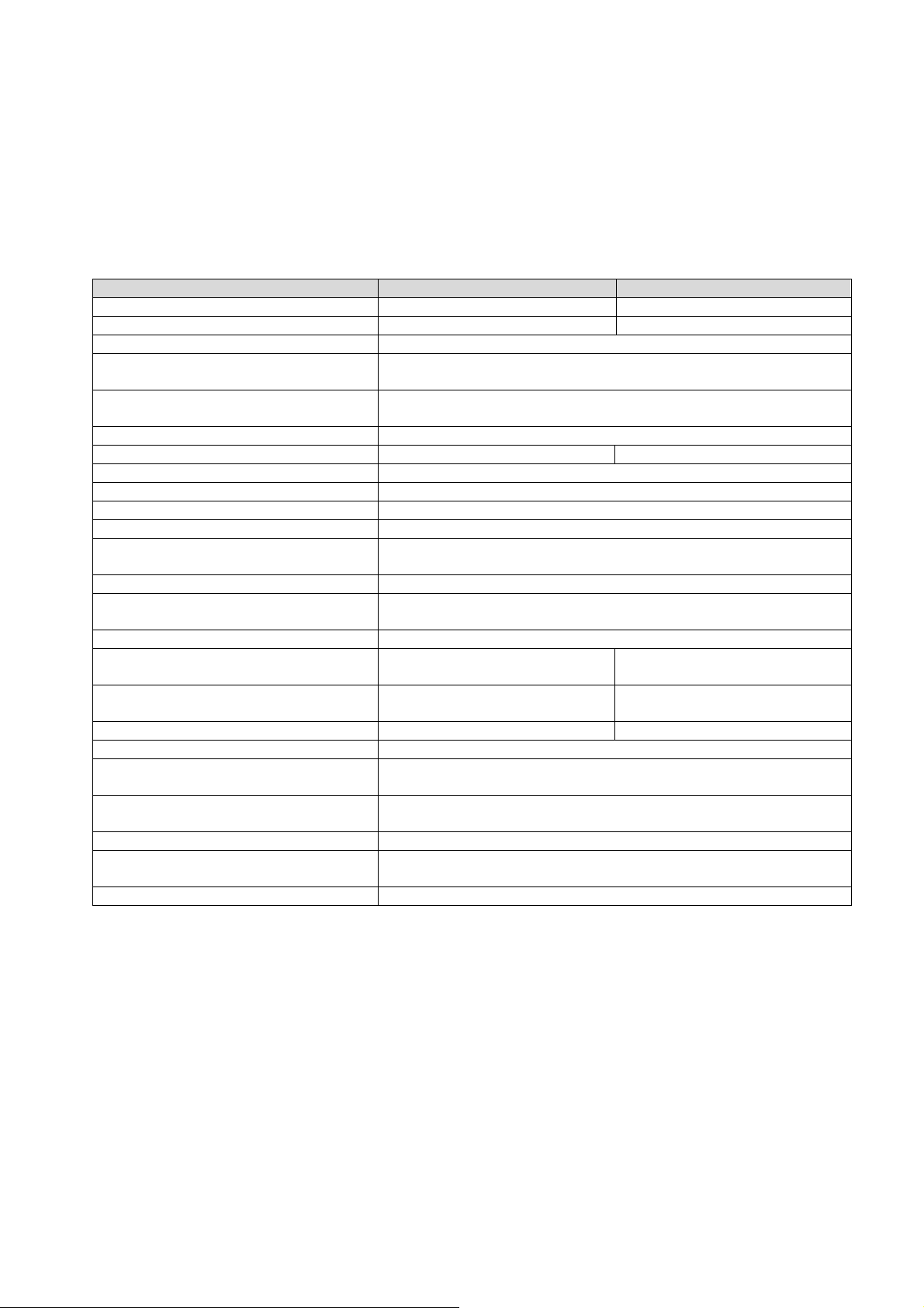
3. Introduction and Specifications
The model LDU 68.x is a precise digital amplifier for weighing and force measurements with strain gauge (SG)
sensors. The LDU 68.2 can be used for industrial applications,the LDU 68.1 can be used in legal for trade as
well as for industrial applications. The device features full multi-drop communications capability and can be
programmed via a straightforward ASCII command set.
The LDU XX.X series and the amplifier DAS 72.1 with on-board digital display, use the same command set.
You can connect up to 32 SG amplifiers of either the LDU XX.X series or DAS 72.1 type onto a single RS 485
bus. The LDU 68.x with its accurate A to D converter and an internal sample rate of up to 90 measurement
values per second, is particularly suitable for static or dynamic measurements and control purposes.
Specifications LDU 68.1 LDU 68.2
Accuracy class III Test certificate according OIML R76 10 000 Teile -
Linearity < 0.002 % FS
Excitation
Analogue input range
Minimum input sensitivity 0.1 μV / d
Certified accuracy according OIML R76 1.0 μV / e Resolution > ± 130 000 counts (input); ± 100 000 counts (output)
Conversion rate 90 values/second internal, up to 90 values/second external
Digital filter IIR filter 0.2 to 5 Hz; Bessel; in 8 steps adjustable
Calibration By software via ASCII commands, sehr einfach durchführbar
Communication interface
Standard weighing functions Gross, tare, net, zero, etc.
Digital inputs
Digital outputs 2x open collector outputs, < 30 V DC, max. 200 mA
Temperature effect on zero
Temperature effect on span
Operation temperature range –15 °C to +55 °C –15 °C to +50 °C
Storage temperature range –30 °C to +70 °C
Enclosure
Dimensions and weight
Power supply 12 ... 24 V DC ±10 %, < 60 mA, not galvanically isolated
Available accesoires
EMC OIML R-76:2006 and DIN EN 45 501:1992/AC1993
5 V DC, load cells 350 – 1 150 Ohm (87,5 – 1 150 Ohm at supply
voltage up to max. 12 V DC); 6 wire technique
±11 mV (bipolar; for weighing applications, force and torque
measurements)
RS485 oder RS422; Voll-Duplex oder Halb-Duplex;
9600 ... 115200 Baud; busfähig bis zu 32 Einheiten
2x opto-isolated inputs, 10 ... 30 V DC max. 3 mA,
Status via software
Typical 7 ppm/°K;
max. < 10 ppm/°K
Typical 2 ppm/°K;
max. < 5 ppm/°K
Typical 25 ppm/°K;
max. < 50 ppm/°K
Typical 15 ppm/°K;
max. < 30 ppm/°K
Tinned steel enclosure, IP40 protection,
special IP65 housing on request
82 x 31 x 6 mm, weighs approx. 30 g;
with adaptor board 99 x 41 x 12 mm, approx. 50 g
Adaptor board UA73.2 (RS485 / RS422) or
Adaptor board UA77.1 (inkl. converter RS422/RS232)
LDU 68.1 & 68.2 Technical Manual, Rev. 12 January 2010
Page 6 of 28
Page 7
4. Communications and Getting started
4.1. Serial Interface
Communicating with the LDU 68.1 digitizer is carried out via the RS422/RS485 port.
The data format is the familiar 8/N/1 structure (8 data bits, no parity, 1 stop bit).
Available baud rates via the RS422/RS485 port are as follows: 9 600, 19 200, 38 400, 57 600 or 115 200 baud.
RS422:
Connection using a 4 wire technique
Point-to-Point connection, i.e. no bus communication possible
Half duplex setup (DX=0)
RS485:
Connection using 2- or 4-wire techniques
Multi-drop connection possible, up to 32 LDU XX.X
Half or Full Duplex (DX=0 or DX=1) possible
(RS232):
The optional adapter board UA 77.1 is available which has an RS485/RS232 converter built in.
4.2. Command Language
The command set of LDU XX.X series is based on a simple ASCII format (2 capital letters). This enables the
user to setup the device, get results or check parameters.
Example: LDU XX.X with the address or channel number 1 is connected via the RS 485 port to a bus system.
You want to get the net weight.
In this manual means: Space “_“ and Enter (CR/LF) ““
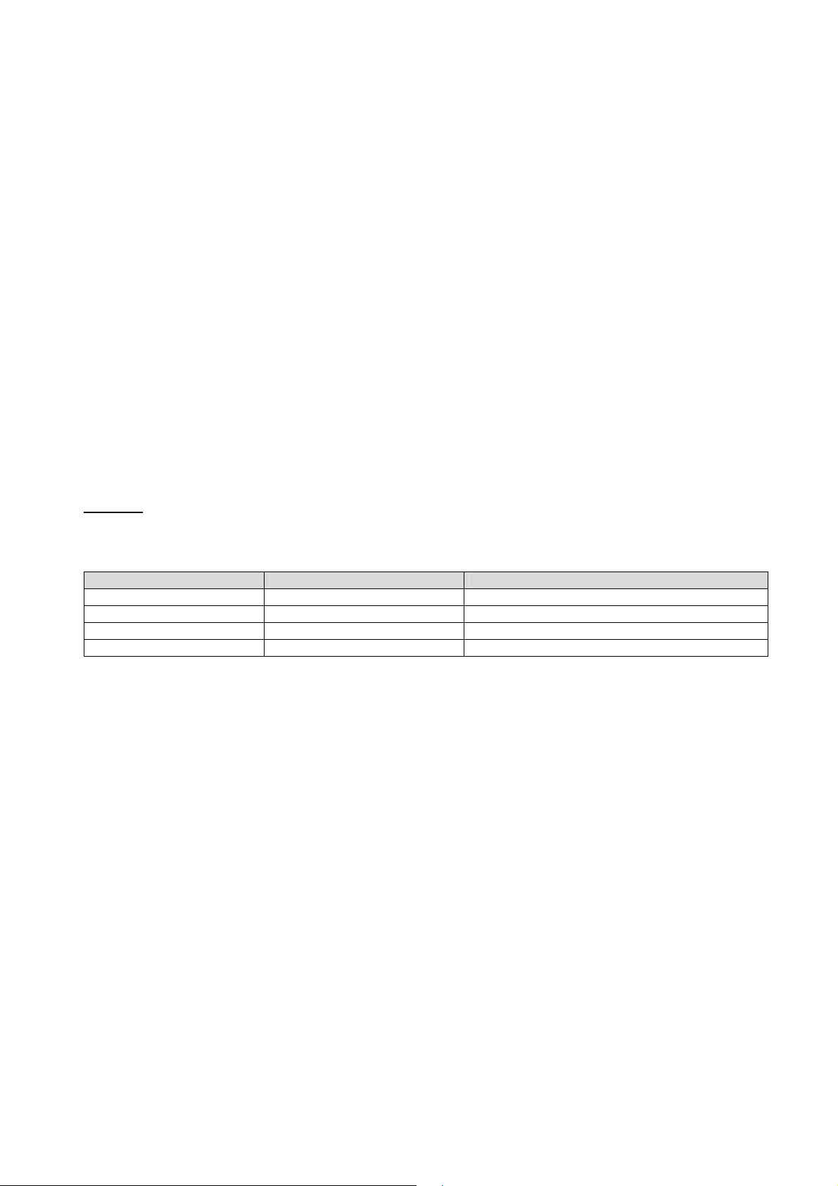
Master (PC / SPS) sends Slave (LDU XX.X) responds Meaning
OP 1
OK
GN
N+123.45
Net weight with algebraic sign / floating point
The command OP_2 opens the communication channel to LDU XX.X device #2. Now device #2 acknowledges
that it is active and responds to any commands on the bus. Communication with device #2 will be closed by
another OP command (for another device on the bus e.g. OP_5) or by the command CL_2.
Each OP_X command implies a CL command to all other devices on the bus except device #X. This makes the
address structures easier and the system performance improves.
Open device #1
Device # 1 ready
Get net weight
LDU 68.1 & 68.2 Technical Manual, Rev. 12 January 2010
Page 7 of 28
Page 8

4.3. Baud Rate / Device Address
Baud Rate:
For baud rate setup use command BR, see chapter 8.10
Factory default: 9 600 baud
Device Address:
For address setup use command AD, see chapter 8.10
Factory default: Address 0
Setting the device address to 0 will set the continuously active mode, where the device becomes permanently
active, and will listen and respond to any command on the bus, without the need for an OP xxx command.
Note: The LDU XX.X series has sets of special solder pads on the under side of the PCB (see chapter 5.1). If
the solder pads are bridged then the LDU will be in a special configuration mode to set up the baud rate and
device address. This function should be used only when baud rate or address is unknown.
After power up, the LDU XX.X will enter a special baud rate search mode – waiting for a space character (0x20)
to be received. The time duration of this character is measured by the LDU and its baud rate timing will be set
accordingly – i.e. the baud rate of the terminal used will be the baud rate used by the LDU subsequently. The
device address will also be set to ”0“
4.4. Getting Started
You will require:
PC or PLC with either a RS422 or RS485 communication port
If using a PC / PLC with RS232 port, a RS422/485 to RS232 converter will be required (option UA 77.1)
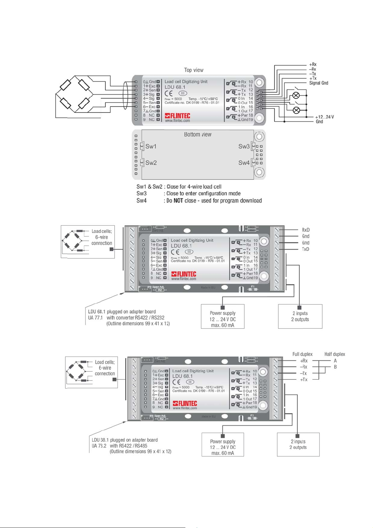
Interconnecting cabling - confirm that all relevant pins are used – see the wiring diagram at the end of
this section
A load cell / scale with test weights or a load cell simulator
A 12-24 VDC power supply capable of delivering approximately 100mA for each LDU and load cell
One or more LDU 68.1
A suitable ASCII communication software *
Refer to the following wiring diagram in chapter 5.
* You can easily communicate between a PC and an LDU using programs such as Procomm, Telemate, Kermit
or HyperTerminal (included in Windows).
Also the DOP software with graphical user interface and oscilloscope function, running under Windows
2000/XP is available as freeware. This software is included on the Flintec product CD-ROM (2008 or later).
LDU 68.1 & 68.2 Technical Manual, Rev. 12 January 2010
Page 8 of 28
Page 9
.
5.
H
W
W
W
h
r
W
r
r
n
1
2
2
2
e
f
ardwa
e and
iring
5.1.
5.2.
iring
ith Unit
Adapte
UA 77.
(RS23
)
5.3.
LDU 68
ith Unit
.1 & 68.2 Tec
Adapte
nical Manual
UA 73.
Rev. 12 Ja
(RS42
uary 2010
/ RS485 Full-/Half-Dupl
x)
Page 9 o
28
Page 10
.
5.4. T
8
o
3
7
e
1
a
h
A
h
p
g
o
n
n
e
e
p
n
c
e
a
h
t
n
.
)
f
+
n
e
n
m
x
e
e
x
n
c
7
7
n
wCom
z
-
n
d
o
o
0
e
n
w
w
)
d
o
a
o
C
C
e
e
o
n
u
u
e
.
f
a
e
LDU 6
Pin n
0
1
2
3
4
5
6
7
8
9
10
11
12
13
14
15
16
17
18
19
Remarks:
UA 7
Valid
UA 7
erminal
.x
.
.2 (see cha
for half-dupl
.1 with inte
U
Gnd (S
+Exc
+ Sens
+ Sig
– Sig
– Sen
– Exc
Gnd
NC
NC
+ Rx
- Rx
- Tx
+ Tx
0 In
0 out
1 In
1 Out
+ PWR
Gnd
Configu
73.2
ield)
ter 5.3) is
ex operatio
rated RS42
ation
UA 77
Gnd (Shield)
+ Exc
+ Sens
+ Sig
– Sig
– Sen
– Exc
Gnd
NC
NC
RxD (RS232
Gnd (RS232
Gnd (RS232
TxD (RS232
0 In
0 out
1 In
1 Out
+ PWR
Gnd
repared for
: pin no. 10
2/RS232 co
1
Co
) Re
) UA
) UA
) Tra
ull-duplex o
+ 13 = A an
verter (see
mon Groun
+ E
citation for l
+ S
nse for load
+ Si
gnal
– Si
gnal
– S
nse for load
– E
citation for l
Sig
al ground /
Not
connected
Not
connected
eive
3.2: Receiv
7.1: Sende
smit
Digi
tal input 0 (w
Digi
tal output 0 (
Digi
tal input 1 (w
Digi
tal output 1 (
Po
er supply 12
mon ground
eration
d pin no. 11
chapter 5.2
Functi
ad cell
cell
cell
ad cell
V DC
/ UA 77.1:
/ UA 77.1:
ith reference
ith referenc
ith reference
ith referenc
...24 V DC
/ 0 V DC
+ 12 = B
on
ommon gro
ommon gro
to ground)
e to ground)
to ground)
e to ground)
nd RS232
nd RS232
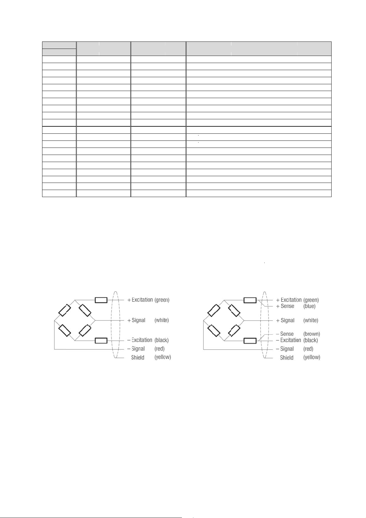
5.5. L
The load c
cells. The i
The sense
chapter 5.
Flintec lo
oad Cell
ll wiring sh
nput resista
pins of the i
) have to b
d cell; 4 wir
Conne
uld be mad
ce of the lo
strument s
short circui
connection
tion
carefully b
d cells that
ould be co
ed.
fore energi
you want to
nected. In 4
Fli
ing to avoi
connect sh
wire install
tec load cel
damages t
uld be more
tions the sw
l; 6 wire con
the amplifi
than 250 Ω
itches SW1
nection
r and the lo
and SW2 (s
d
e
LDU 68
.1 & 68.2 Tec
nical Manual
Rev. 12 Ja
uary 2010
Page 10 o
28
Page 11
6. Calibration and Calibration Sequence
The calibration of LDU 68.x is only possible after starting a calibration sequence (compare with chapter 8.2).
Command CE: Calibration enable – returns the current TAC value
Command CM: Calibrate maximum display – sets the max. allowable display value
Command CI: Calibrate minimum – sets the minimum allowable display value
Command DS: Display step size – sets the output incremental step size
Command DP: Decimal point – sets the position of the output decimal point
Command CZ: Calibrate zero – sets the system zero point
Command CG: Calibrate gain – sets the system gain
Command ZT: Zero track enable / disable
Command FD : If applicable: Factory default setting (return to)
Command CS : Calibration save (TAC counter automatically incremented by 1)
Preparing the calibration:
Check, if the max value of the display is set sufficiently high (see chapter 8.2: command CM)
Check, if the no motion conditions are defined reasonable (chapter 8.3: e.g. NR = 1, NT = 1000)
Set the filter frequency to 0.5 Hz (see chapter 8.4: FL = 3)
Example: Setup of zero point, system gain and decimal point
The chosen calibration weight has the value 5000 (increments). That could be 500 g, 5 kg or 5000 kg. We
calibrate with 500 g. The decimal point is set up by command DPx (x = 1, 2 or 3), here 1 figure after the
decimal point. A measured weight of 500 g is displayed as 500.0.
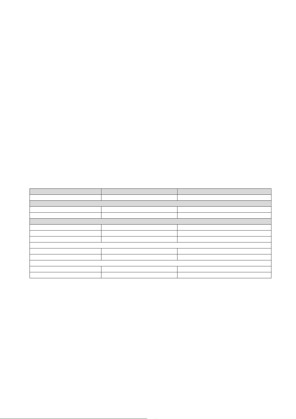
Master (PC / SPS) sends Slave (LDU XX.X) responds Meaning
CE E+00017 (example)
Adjust zero: The scale has to be empty. No load!
CE 17 OK
CZ OK
Adjust gain: First put the calibration weight on the scale (here 500 g)!
CE 17 OK
CG 5000 OK
CG G+05000
CE 17 OK
DP 1 OK
CE 17 OK
CS OK
Zero point, gain and decimal point position were saved in the EEPROM; the calibration counter (TAC) is
increased automatically by 1.
Request: TAC counter CE17
Calibration sequence active
System zero point saved
Calibration sequence active
Setting span
Request: span 5000 d
Calibration sequence active
Setting: decimal point 0000.0
Calibration sequence active
Save calibration data in EEPROM
LDU 68.1 & 68.2 Technical Manual, Rev. 12 January 2010
Page 11 of 28
Page 12

7. Commands – Overview
Command Short description Parameter value Page
AD
A0/A1
BR
CE
CI
CG
CL
CM
CS
CZ
DP
DS
DX
FD
FF
FL
GA
GF
GG
GI
GN
GS
GT
GW
H0/H1
ID
IM
IN
IO
IS
IV
MT
NR
NT
OP
PI
RS
RT
RZ
SA
SD
SF
SG
SN
S0/S1
SR
SS
ST
SW
SZ
TD
TE
TL
TR
UR
WP
ZI
ZT
Communication: Device Address 0...255 23
Setpoints: Output of Gros Value (0) or Net Value(1) 0 or 1 22
Communication: Baud Rate 9600…115200 baud 23
Calibration: Open Calibration Sequence; Read TAC Counter 0...65535 14
Calibration: Minimum Output Value –99999...0 d 14
Calibration: Set Calibration Gain (Span) at Load > Zero 0...99999 15
Communication: Close Device None 23
Calibration: Set Maximum Output Value 1...99999 d 14
Save the Calibration Data (CM, CI, DS, DP, CZ, CG, etc.) to EEPROM None
Calibration: Set Calibration Zero Point – scale without load None
Calibration: Set Decimal Point Position 0...5 14
Calibration: Set Display Step Size 1, 2, 5, 10…, 200 14
Communication: Set Half-duplex (0) or Full-duplex (1) 0 or 1 23
Factory default settings: Write data to EEPROM (TAC protected) None 15
Digital filter: Moving Average 0…15 17
Digital filter: Filter Cut-off Frequency 0...7 17
Trigger function: Get Average Value None 25
Output: Get Filtered Value None
Output: Get Gross Value None
Saves an image file from the LDU’s EEPROM None 24
Output: Get Net Value None
Output: Get ADC Sample Value None
Output: Get Tare Value None
Output: Get Data String “Net/Gross/Status“ None
Setpoints: Hysteresis for Setpoint S0 (H0) or S1 (H1) -99999...+99999 d 22
Device information: Identify Device None
Digital output: Enable Output for External Control 0000...0011 21
Digital input: Input Status None 21
Digital output: Output Status 0000...0011 21
Device information: Identify Device Status None
Device information: Identify Firmware Version None
Trigger function: Measuring Time for Averaging 0...500 ms 25
Motion detection: No-motion Range 0...65535 d 16
Motion detection: No-motion Time Period 0...65535 ms 16
Communication: Open Device xxx 0...255 23
Download a saved image file to the LDU’s EEPROM None 24
Device information: Read serial number None 13
Scale function: Reset Tare and Switch to Gross Indication None
Scale function: Reset Zero Point None
Auto-transmit: Send Triggered Average Value automatically None 20, 25
Trigger function: Start Delay 0...500 ms 25
Auto-transmit: Send Filtered Net Value continuously (Display Mode only) None
Auto-transmit: Send Gross Value continuously None
Auto-transmit: Send Net Value continuously None
Setpoints: Setup of Setpoints S0 and S1 -99999...+99999 d 22
Reset Firmware (Warm Start) None
Save Setpoint Data (S0, S1, H0, H1, A0 and A1) to EEPROM None 24
Scale function: Set Tare and Switch to Net Indication None
Auto-transmit: Send Data String „Net/Gross/Status“ continuously None
Scale function: Set Zero None 18
Communication: Transmission delay 0…255 ms 23
Trigger function: Trigger on Rising Edge (1) or Falling Edge (0) 0 or 1 25
Trigger function: Trigger Level 0...99999 d 26
Trigger function: Software Trigger None 25
Digital filter: Update Rate 0...2 17
Save the Setup Data (FL, NR, NT, AD, BR, DX) to EEPROM None 24
Calibration: Initial Zero Range 0...99999 d 15
Zero Tracking: Disable (0) or Enable (1) 0 or 1 15
15, 24
14
19
19
19
19
19
19
13
13
13
18
18
20
20
20
13
18
20
LDU 68.1 & 68.2 Technical Manual, Rev. 12 January 2010
Page 12 of 28
Page 13
8. Commands Description
For better clarity, all commands are divided into groups as described on the following pages.
8.1. System Diagnosis Commands – ID, IV, IS, SR, RS
Use these commands you get the LDU XX.X type, firmware version or device status. These commands are
sent without parameters.
8.1.1. ID Get Device Identity
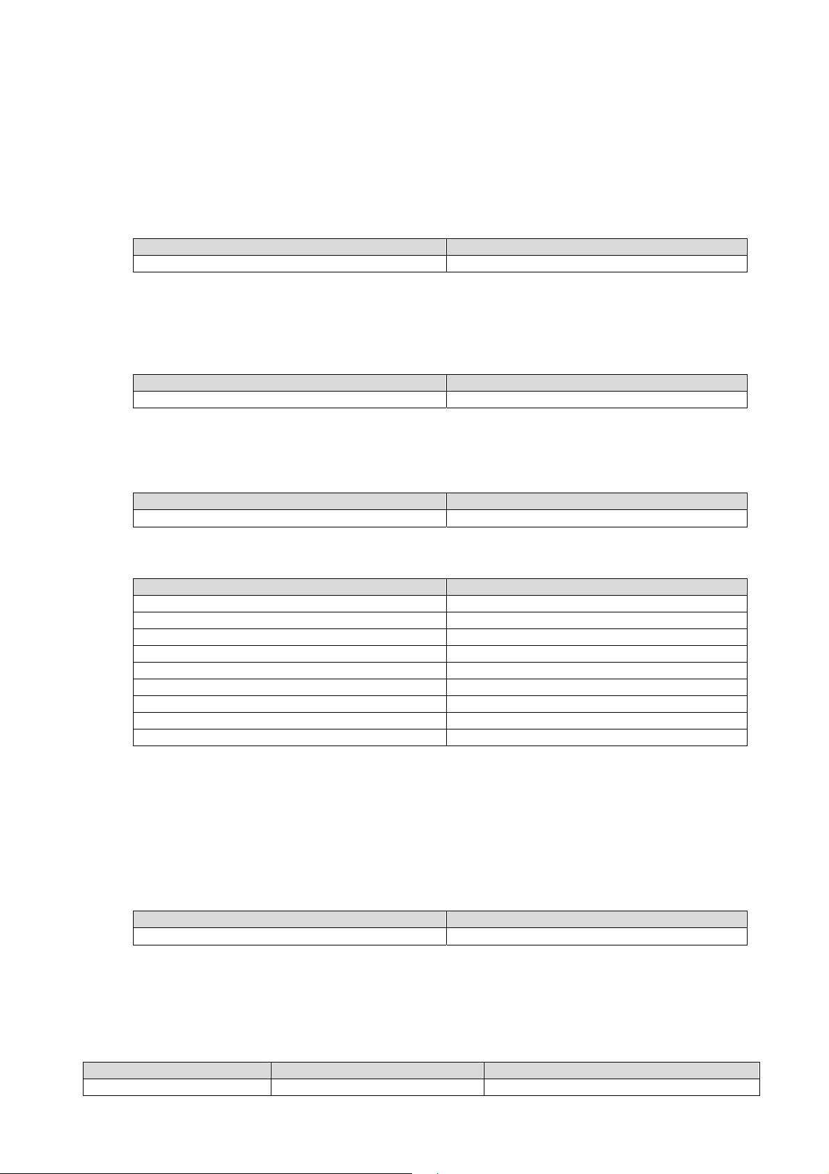
Master (PC / SPS) sends Slave (LDU XX.X) responds
The response to this request gives the actual identity of the active device. This is particularly useful when trying
to identify different device types on a bus.
8.1.2. IV Get Firmware Version
Master (PC / SPS) sends Slave (LDU XX.X) responds
The response to this request gives the firmware version of the active device.
8.1.3. IS Get Device Status
Master (PC / SPS) sends Slave (LDU XX.X) responds
The response to this request comprises of two 3-digit decimal values (067 and 000), which can be decoded
according to the table below:
Leftmost 3-digit value Rightmost 3-digit value
1 Signal stable (no motion) 1 (not used)
2 Zeroing action performed 2 (not used)
3 Tare active 3 (not used)
4 (not used) 4 (not used)
8 (not used) 8 (not used)
16 (not used) 16 (not used)
32 (not used) 32 (not used)
64 (Setpoint-) output 0 active 64 (not used)
The example decodes the result S:067000 as follows:
Note: The bits that are not used are set to zero.
128 (Setpoint-) output 1 active 128 (not used)
Signal stable (no motion) [20 = 1, LSB]
Zeroing action performed [2
Tare not active [= 0]
ID D:6813
IV V:0400
IS
1
= 2]
S:067000 (example)
Output 0 active [27 = 64]
Output 1 not active [= 0]
8.1.4. SR Reset LDU XX.X Firmware
Master (PC / SPS) sends Slave (LDU XX.X) responds
SR OK
This command will respond with ‘OK’ and after maximum 400 ms perform a complete reset of the LDU. It has
the same functionality as power off and on again.
8.1.5. RS Read Serial Number
Issuing the RS command will return the current serial number in the format S:12345678.
Master (PC / SPS) sends Slave (LDU XX.X) responds Meaning
RS S:123456789
LDU 68.1 & 68.2 Technical Manual, Rev. 12 January 2010
Request: RS = 12345678
Page 13 of 28
Page 14
8.2. Calibration Commands – CE, CM, DS, DP, CZ, CG, ZT, ZI, FD, CS
8.2.1. CE Read TAC* Counter / Open Calibration Sequence
With this command you can read the TAC counter (*TAC = Traceable Access Code) or you can open a
calibration sequence.
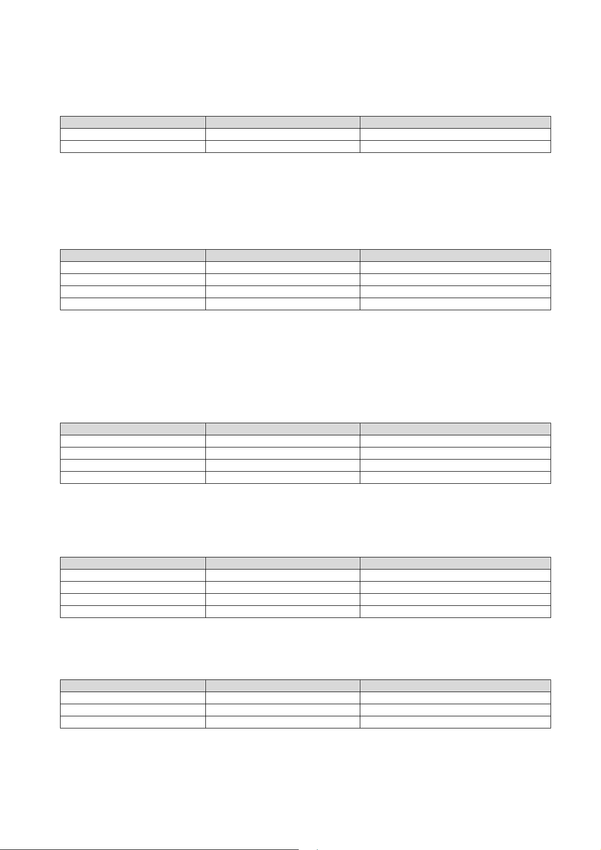
Master (PC / SPS) sends Slave (LDU XX.X) responds Meaning
CE E+00017 (example)
CE 17 OK
This command must be issued PRIOR to any attempt to set the calibration parameters CM n, CI, MR, DS, DP,
CZ, CG, ZT, ZR, FD, LC, LN n or CS. In legal for trade applications the TAC counter can be used to check if
critical parameters have been change without re-verification. After each calibration the TAC counter increases
by 1.
8.2.2. CM Set Maximum Output Value
This command is used to set up the maximum output value. Permitted values are from 1 to 99 999.
Master (PC / SPS) sends Slave (LDU XX.X) responds Meaning
CM 1 M+030000
CE E+00017 (example)
CE 17 OK
This value will determine the point at which the output will change to “oooooo”, signifying over-range respective
the point at which the output will change the measuring range / interval size.
Note: The range, in which a scale can be set to zero (SZ) or automatic zero tracking (ZT) is active, is +/- 2% of
CM value. Factory default: CM = 99 999
CM 1 50000 OK
Request: TAC counter CE17
Calibration sequence active
Request: CM 1 = 30 000 d
Request: TAC counter CE17
Calibration sequence active
Setup: CM 1 = 50 000 d
8.2.3. DS Set Display Step Size
This command allows the output to step up or down by a unit other than 1.
Permitted values are 1, 2, 5, 10, 20, 50, 100 and 200.
Master (PC / SPS) sends Slave (LDU XX.X) responds Meaning
DS S+00002
CE E+00017 (example)
CE 17 OK
DS 50 OK
Request: Step size 2
Request: TAC counter CE17
Calibration sequence active
Setup: Step size 50
Legal for trade applications allow for 3000, 4000 or 5000 intervals. The allowed step size has to be considered.
8.2.4. DP Set Decimal Point Position
This command allows the decimal point to be positioned anywhere between leftmost and rightmost digits of the
5-digit output result. Position 0 means no decimal point. Factory default: DP = 3
Master (PC / SPS) sends Slave (LDU XX.X) responds Meaning
DP P+00002
CE E+00017 (example)
CE 17 OK
DP 0 OK
Request: Position of decimal point 2
Request: TAC counter CE17
Calibration sequence active
Setup: no decimal point
8.2.5. CZ Set Calibration Zero Point
This is the reference point for all weight calculations, and is subject to TAC control.
Factory default: approx. 0 mV/V input signal
Master (PC / SPS) sends Slave (LDU XX.X) responds Meaning
CE E+00017 (example)
CE 17 OK
CZ 0 OK
Request: TAC counter CE17
Calibration sequence active
Zero point saved
LDU 68.1 & 68.2 Technical Manual, Rev. 12 January 2010
Page 14 of 28
Page 15
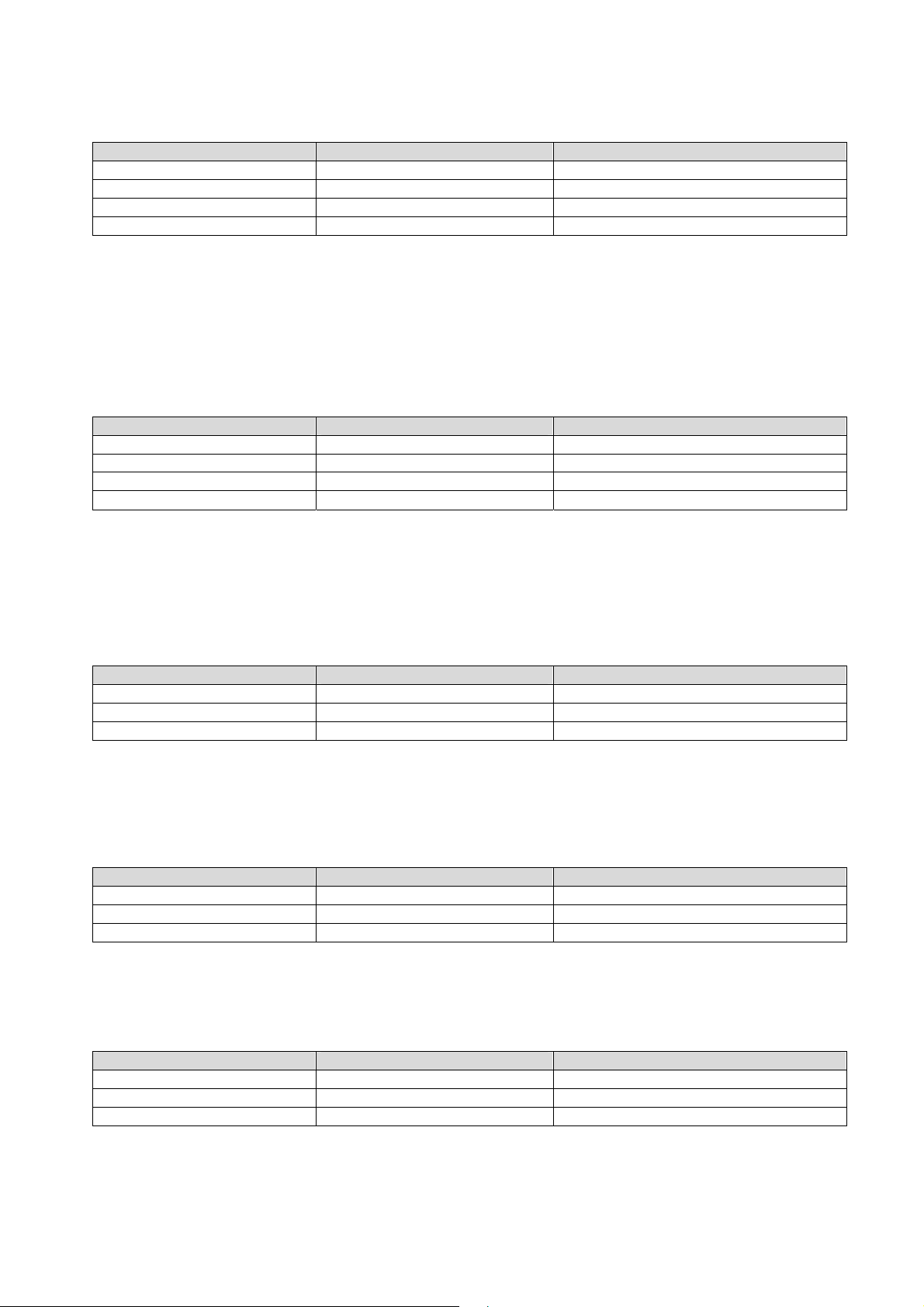
8.2.6. CG Set Calibration Gain (Span)
This is the reference point for calibration under load, and is subject to TAC control.
Permitted values are from 1 to 99 999.
Master (PC / SPS) sends Slave (LDU XX.X) responds Meaning
CG G+10000
CE E+00017 (example)
CE 17 OK
CG 15000 OK
Request: Calibration weight = 10 000 d
Request: TAC counter CE17
Calibration sequence active
Setup: Calibration weight = 15 000 d
For calibration an input signal near the display maximum (CM) will give the best system performance. The
minimum calibration load of at least 20% is recommended. Is the calibration weight smaller than 1% of display
maximum (CM), the LDU will respond with an error message (“ERR”).
Factory default: 20 000 = 2.000 mV/V input signal
8.2.7. ZT Enable / Disable Zero Tracking
This command enables or disables the zero tracking. ZT = 0 disables the zero tracking and ZT = 1 enables the
zero tracking. Issuing the command without any parameter returns the current ZT value.
Master (PC / SPS) sends Slave (LDU XX.X) responds Meaning
ZT Z:001
CE E+00017 (example)
CE 17 OK
ZT 0 OK
Zero tracking will be performed only on results less than +/-0.5 d at a rate of 0.4 d/sec, where d = display step
size (see DS command). The zero can only be tracked to +/- 2% of maximum (see CM n command).
Factory default: ZT = 0 [Disable]
Request: ZT status
Request: TAC counter CE17
Calibration sequence active
Setup: ZT = Disable
8.2.8. ZI Initial Zero Range
Defines the initial zero range (0…99999 d). If ZI is non-zero the device will perform an automatic Set-Zero
when the weight stabilizes with the No-motion settings and the weight is within the ZI range. Factory default: 0.
Master (PC / SPS) sends Slave (LDU XX.X) responds Meaning
CE E+00017 (example)
CE 17 OK
ZI 100 OK
Request: TAC counter CE17
Calibration sequence active
Setup: Initial Zero range = 100 d
8.2.9. FD Reset to Factory Default Settings
This command puts the LDU back to a known state. The data will be written to the EEPROM and the TAC will
be incremented by 1.
Note: All calibration and setup information will be lost by issuing this command!
Master (PC / SPS) sends Slave (LDU XX.X) responds Meaning
CE E+00017 (example)
CE 17 OK
FD 0 OK
Request: TAC counter CE17
Calibration sequence active
Factory default setting
8.2.10. CS Save the Calibration Data
This command results in the calibration data being saved to the EEPROM and causes the TAC to be
incremented by 1.
Master (PC / SPS) sends Slave (LDU XX.X) responds Meaning
CE E+00017 (example)
CE 17 OK
CS OK
The CS command saves all of the calibration group values, as set by CZ, CG, CM n, DS, DP and ZT. The
command returns ERR and has no updating action unless it is preceded by the CE_XXXXX.
Request: TAC counter CE17
Calibration sequence active
Calibration values saved
LDU 68.1 & 68.2 Technical Manual, Rev. 12 January 2010
Page 15 of 28
Page 16
8.3. Motion Detection Commands – NR, NT
The motion detection facility provides a means of disabling certain functions whenever a condition of instability,
or “motion”, is detected. The “no-motion”, or “stable” condition is achieved whenever the signal is steady for the
period of time set by NT, during which it cannot fluctuate by more than NR increments.The stable condition
activates the relevant bit of responses to “Info Status” (IS).
Following functions are disabled if motion is detected: “Calibrate Zero” (CZ) “Calibrate Gain” (CG) “Set Zero”
(SZ) and “Set Tare” (ST). After such a command the system returns an error (“ERR“), if the signal is not stable.
8.3.1. NR Set No-motion Range
This is the range within which the weighing signal is allowed to fluctuate and still be considered as “stable”.
Permitted values are from 1 to 65535.
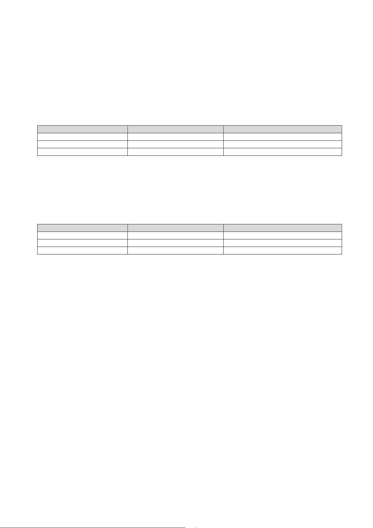
Master (PC / SPS) sends Slave (LDU XX.X) responds Meaning
NR R+00010
NR 2 OK
WP OK
Example: For NR = 2 the fluctuations within a maximum of ± 2 d, in the period NT, will be considered “stable”.
Factory default: NR = 1 [= ±1d]
8.3.2. NT Set No-motion Time Period
This is the time period (in milliseconds) over which the weight signal is checked to see if it is “stable” or has “nomotion“. The weight signal has to vary by less than NR divisions over the time period NT to be considered
‘stable’. Permitted values are from 1 to 65 535.
Master (PC / SPS) sends Slave (LDU XX.X) responds Meaning
NT T+01000
NT 500 OK
WP OK
If the value of NT =500 milliseconds, the output must not fluctuate more than NR increments within 500
milliseconds in order to be considered “stable”.
Factory default: NT = 1 000 [ms]
Request: NR = 10 d
Setup: NR = 2 d
Setup saved
Request: NT = 1 000 ms
Setup: NT = 500 ms
Setup saved
LDU 68.1 & 68.2 Technical Manual, Rev. 12 January 2010
Page 16 of 28
Page 17
8.4. Filter Setting Commands – FL, FF, UR
A digital filter can be set which will eliminate most of the unwanted disturbances. The commands FL and FF are
used to define the digital filter settings, the command UR is used to define an averaging of up to 90
measurement values. Please note that these filters are positioned immediately after the A/D Converter and
therefore affect all aspects of the weighing operation.
8.4.1. FL Filter Settings
This command defines the filter cut off frequency and the filter characteristics. The digital IIR filter operates as
nd
2
order low pass filter and Bessel characteristics. The attentuation is 40dB/decade (12 dB/octave).
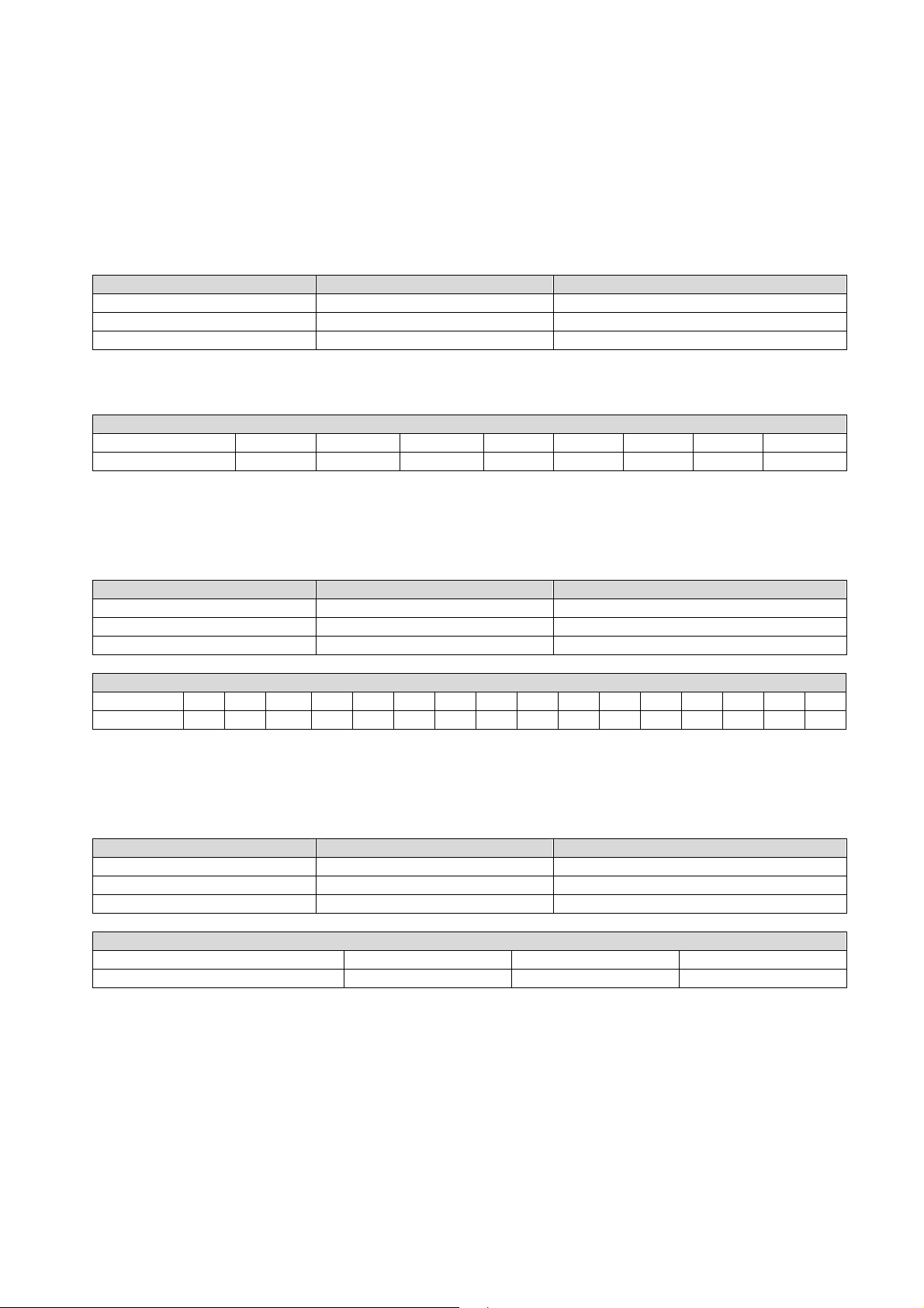
Master (PC / SPS) sends Slave (LDU XX.X) responds Meaning
FL F+00003
FL 1 OK
WP OK
The permitted settings are from 0 to 7 (see table below).
Factory default setting: FL = 3 (Bessel 0.5 Hz).
Filter Cut-off Frequencies
FL = 7 6 5 4 3 2 1 0
Cut-off frequency 0.02 Hz 0.05 Hz 0.1 Hz 0.2 Hz 0.5 Hz 1 Hz 2 Hz 5 Hz
8.4.2. FF Moving Average
This command defines a moving average for the output value. The permitted settings are from 0 to 15 (see
table below). Factory default setting: FF = 0 (0.2 s)
Master (PC / SPS) sends Slave (LDU XX.X) responds Meaning
FF F+00001
FF 4 OK
WP OK
Moving Average
FF = 0 1 2 3 4 5 6 7 8 9 10 11 12 13 14 15
sec 0.2 0.4 0.6 0.8 1.0 1.2 1.4 1.6 1.8 2.0 2.2 2.4 2.6 2.8 3.0 3.2
Request: FL = 3
Setup: FL = 1
Setup saved
Request: FF = 1 (0.4 s)
Setup: FF = 4 (1 s)
Setup saved
8.4.3. UR Update Rate
This command defines the update rate of the output value. The permitted settings are from 0 to 2 (see table
below). Factory default setting: UR = 2 (30 values/s)
Master (PC / SPS) sends Slave (LDU XX.X) responds Meaning
UR U+0000
UR 2 OK
WP OK
Update Rates
UR 0 1 2
Values / second 90 45 30
Request: 90 values/s active
Setup: 30 values/s
Setup saved
LDU 68.1 & 68.2 Technical Manual, Rev. 12 January 2010
Page 17 of 28
Page 18

8.5. Taring and Zeroing Commands – SZ, RZ, ST, RT
The following commands allow you to set and reset the zero and tare values. The zero set up during calibration
remains the ‘true zero’ but the new ‘current zero’ can be set up by using the SZ command. If the SZ command
is issued and accepted then all weight values will then be based on the new ‘current zero’. Please remember
that the zero value will be subject to the Zero tracking function if enabled.
If the weight signal is not stable (as defined by the No motion range NR and the No motion time NT) then both
the set zero SZ and set tare ST commands will be disabled.
Also the Set Zero SZ command is not allowed if the new zero value required and the ‘calibration zero’ differ by
more than 2 % of the CM value (maximum allowable value).
See chapter 9 Used in “Approved” applications.
8.5.1. SZ Set Zero
This command sets a new “current zero” which is then the basis of all weight values until further updated by the
zero tracking function, another SZ command or the “reset zero” command RZ.
Master (PC / SPS) sends Slave (LDU XX.X) responds Meaning
SZ OK
The SZ command will fail (LDU responds with ERR) if the new “current zero” is more than 2% (of the CM value)
higher or lower than the “true zero” set during calibration. The SZ command will also fail if the weight signal is
not stable as defined by the No motion range (NR) and the No motion time (NT). If the weight signal is “stable”,
the response to the IS command (Device Status) will show the “signal stable” bit active and the SZ command
will be accepted (OK). If the “signal stable” bit is not active, the SZ command will be rejected and the LDU will
respond with ERR (error).
Set zero performed
8.5.2. RZ Reset Zero Point
This command cancels the SZ command and the zero reading reverts to that set by the CZ command during
calibration.
Master (PC / SPS) sends Slave (LDU XX.X) responds Meaning
RZ OK
Zero point CZ active
The LDU responds to the RZ command with either OK or ERR. If OK is returned then the “zero action
performed” bit in the Device Status (IS) response will be set to “0”.
8.5.3. ST Set Tare
This command will activate the net weighing function by storing the current weight value as a tare.
The weight signal must be “stable” within the limits set by NR (No Motion Range) and NT (No Motion Time)
commands for the “signal stable” bit to be active and set tare command to be accepted.
Master (PC / SPS) sends Slave (LDU XX.X) responds Meaning
ST OK
Tare performed / Net operation
If the weight signal is “stable”, the response to the IS command (Device Status) will show the “signal stable” bit
active and the ST command will be accepted (OK). If the “signal stable” bit is not active, the ST command will
be rejected and the LDU will respond with ERR (error).
8.5.4. RT Reset Tare
This command resets the tare and the weighing signal returns to gross mode.
Master (PC / SPS) sends Slave (LDU XX.X) responds Meaning
RT OK
The LDU responds to the RT command with either OK or ERR. If OK is returned then the “tare active” bit in the
Device Status (IS) response will be set to “0”.
Tare de-activated / Gross operation
LDU 68.1 & 68.2 Technical Manual, Rev. 12 January 2010
Page 18 of 28
Page 19
8.6. Output Commands – GG, GN, GT, GS, GF, GW, GA
The following commands “Get” the gross, net, tare and ADC sample values from the LDU 68.1.
8.6.1. GG Get Gross Value
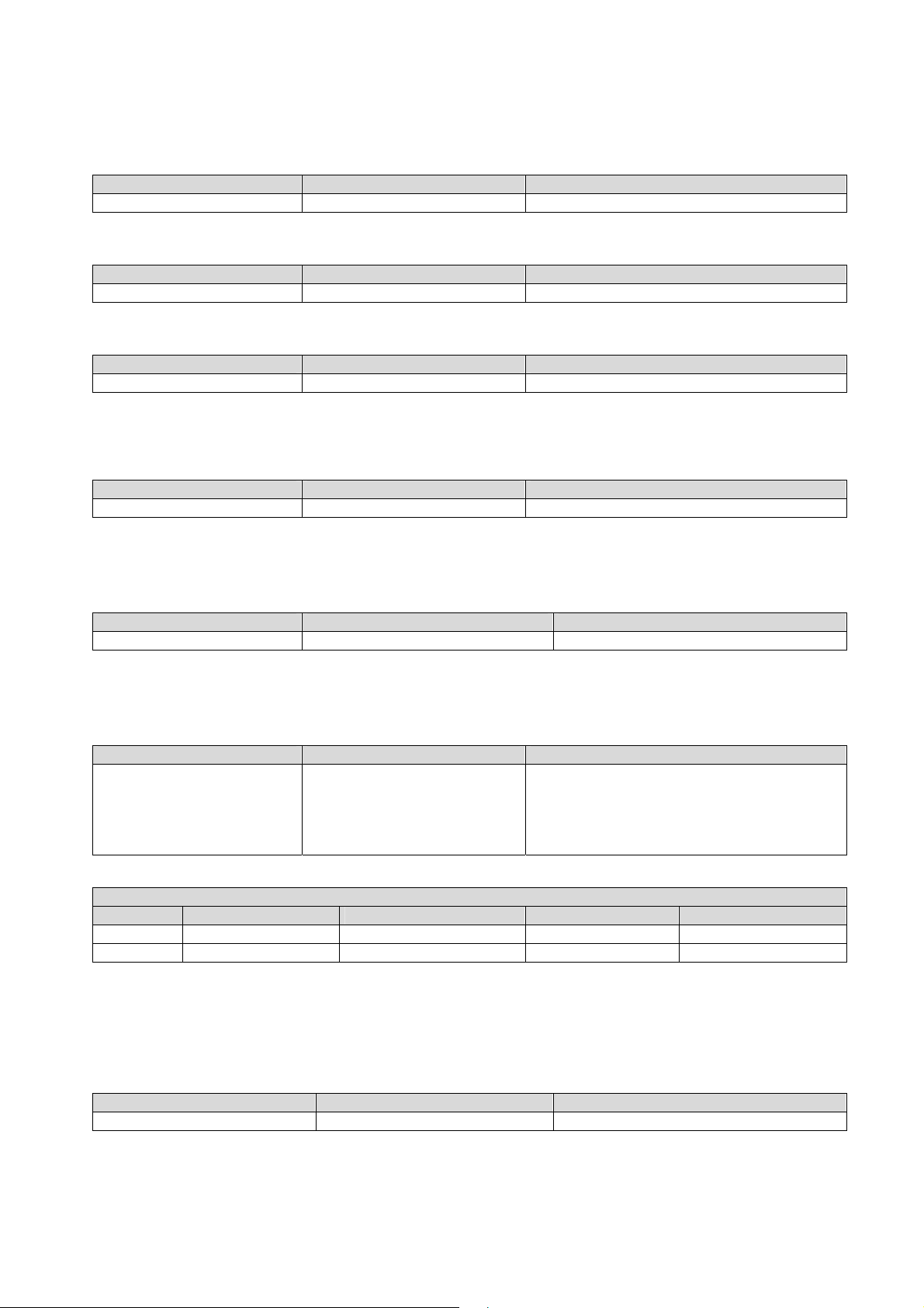
Master (PC / SPS) sends Slave (LDU XX.X) responds Meaning
GG G+01.100
8.6.2. GN Get Net Value
Master (PC / SPS) sends Slave (LDU XX.X) responds Meaning
GN N+01.000
8.6.3. GT Get Tare Value
Master (PC / SPS) sends Slave (LDU XX.X) responds Meaning
GT T+00.100
8.6.4. GS Get ADC Sample Value
This command gets the actual Analogue to Digital Converter (ADC) value. This can be useful during
development or when calibrating to see how much of the ADC range is being used.
Master (PC / SPS) sends Slave (LDU XX.X) responds Meaning
For service purposes it may be helpful to note the GS values for the “no-load” or “zero” output and when the
“calibration load” is applied.
GS S+125785
Gross value: 1.100 d
Net value: 1.000 d
Tare value: 0,100 d
ADC sample value = 125785 d
8.6.5. GF Get Filtered Value
Master (PC / SPS) sendet Slave (LDU XX.X) antwortet Meaning
GF F+01.000
Filterted net value: 1,000 d
This command provides the filtered net value, e.g. for the weight display. The filtering is done according the
command FF (see chapter 8.4.)
8.6.6. GW Get Data String “Net, Gross and Status“
Master (PC / SPS) sends Slave (LDU XX.X) responds Meaning
Net value: +000100 d (no decimal point)
GW
The status bits 1 and 2 are defined as follows:
W+000100+0011005109
(example)
Gross value: +001100 d (no decimal point)
Status bit 1: 5 (not used)
Status bit 2: 1 (Hex)
Check sum: 09 (Hex)
Status
Value = 1 Value = 2 Value = 4 Value = 8
Status bit 1 Not used Not used Output 0 active Output 1 active
Status bit 2 Signal stable Set zero performed Tare active Not used
The check sum is the reciprocal value of the sum of all ASCII values within the data string without the check
sum itself.
8.6.7. GA Get Triggered Average Value
This command reads the measurement result of a measurement cycle. The measurement value has been
averaged according the defined measuring time. The trigger commands can be found in chapter 8.12.
Master (PC / SPS) sends Slave (LDU XX.X) responds Meaning
GA A+01.100
Note: For preventing errors during the read out of the data the register GA has stored the value 99999 at the
beginning of the measurement cycle. The measurement result can only be read after the defined measuring
time MT has been elapsed and before a new measurement cycle has been started.
Request: GA = 1100 g
LDU 68.1 & 68.2 Technical Manual, Rev. 12 January 2010
Page 19 of 28
Page 20
8.7. Auto–transmit Commands – SG, SN, SF, SW, SA
The following commands allow the gross weight or net weight values to be continuously sent. Continuous
transmission start as soon as the relevant command has been issued and finishes when any other valid
command is accepted by the LDU 68.1. The data output rate will depend on the baud rate being used e.g. with
a baud rate of 9 600, approximately 100 values per second can be transmitted.
Note: The SG, SN and SW commands will only work if the LDU 68.1 has been set to full duplex [DX=1].
The continuous transmission of either the gross or net values will stop when another valid command is
received.
8.7.1. SG Send Gross Value continuously
Master (PC / SPS) sends Slave (LDU XX.X) responds Meaning
SG G+01.100
8.7.2. SN Send Net Value continuously
Master (PC / SPS) sends Slave (LDU XX.X) responds Meaning
SN N+01.000
8.7.3. SF Send Filtered Value continuously (Display Mode only)
Master (PC / SPS) sends Slave (LDU XX.X) responds Meaning
SF F+01.000
This command will start to auto-transmit the post-filtered net weight value, e.g. for a weight display. The filter
setup will be done with the command FF (see chapter 8.4.).
Gross value: 1,100 d
Net value: 1,000 d
Filterted net value: 1,000 d
8.7.4. SW Send Data String “Net, Gross and Status“ continuously
Master (PC / SPS) sends Slave (LDU XX.X) responds Meaning
Net value: +000100 d (no decimal point)
Gross value: +001100 d (no decimal point)
Status bit 1: 5 (not used)
Status bit 2: 1 (Hex)
SW
W+000100+0011005109
(example)
Check sum: 09 (Hex)
The status bits 1 and 2 are defined as follows:
Status
Value = 1 Value = 2 Value = 4 Value = 8
Status bit 1 Not used Not used Output 0 active Output 1 active
Status bit 2 Signal stable Set zero performed Tare active Not used
The check sum is the reciprocal value of the sum of all ASCII values within the data string without the check
sum itself.
8.7.5. SA Send Triggered Average Value automatically
Master (PC / SPS) sends Slave (LDU XX.X) responds Meaning
SA A+01.100
This command will start to auto-transmit the measurement value of the current trigger cycle. The trigger setup
commands are described in chapter 8.12.
Measurement value: 1,100 d
LDU 68.1 & 68.2 Technical Manual, Rev. 12 January 2010
Page 20 of 28
Page 21
8.8. Commands for External I/O Control – IN, IO, IM
The LDU 68.1 has 2 independent logic inputs and 2 independent logic outputs. These inputs and outputs can
be configured and controlled completely via the LDU. The logic inputs can be read directly by the host
application and the logic outputs can be fully controlled via the setpoint commands.
The following group of commands allows the status of the 2 logic inputs to be read, the status of the 2 logic
outputs to read or modified and to configure the logic outputs for internal or external control.
The use of the setpoint commands (Sn, Hn, An) are explained in the following chapter 8.9.
8.8.1. IN Read the Status of the Input Channels
This command reads the status of the two logic inputs.
Master (PC / SPS) sends Slave (LDU XX.X) responds Meaning
IN IN:0001
IN IN:0010
IN IN:0011
The status response is in the form of a four digit code where 0 = false and 1 = true (inputs are active “high”), the
least significant bit corresponding to Input 0 etc.
8.8.2. IO Read / Set the Status of the Output Channels
This command reads and can modify the status of the two logic outputs (if enabled by the IM command).
Master (PC / SPS) sends Slave (LDU XX.X) responds Meaning
IO IO:0001
IO IO:0010
IO IO:0011
IO 0001 OK
IO 0010 OK
IO 0011 OK
The status response is in the form of a four digit code where 0 = false and 1 = true (outputs are normally open,
open drain MOSFETs), the least significant bit corresponding to Output 0 etc.
The status of the outputs can be changed by issuing the IO command with the appropriate 4 digit code e.g. IO
0001 where in this example output 0 will be activated (FET conducting). Please note that the status of the logic
outputs is normally determined by the internal setpoints (see chapter 8.10) and therefore setting the logic
output status using the IO commands is not allowed.
However, the IM command can be used to allow the status of the logic outputs to be set via the IO command or
set their status directly by the host application. Factory default: IO=0000
Request: Input 0 is active
Request: Input 1 is active
Request: Inputs 0 and 1 are active
Request: Output 0 is active
Request: Output 1 is active
Request: Outputs 0 and 1 are active
Setup: Output 0 is active
Setup: Output 1 is active
Setup: Outputs 0 and 1 are active
8.8.3. IM Control of the logic outputs by the host application
The logic outputs can be controlled by the host application (as opposed to the normal internal setpoints) if they
are enabled by the IM command and the appropriate 4 digit code.
Master (PC / SPS) sends Slave (LDU XX.X) responds Meaning
IM IM:0001
IM IM:0010
IM IM:0011
IM 0001 OK
IM 0010 OK
IM 0011 OK
IM 0000 OK
A “1” bit in the code enables the corresponding logic output to be controlled by the host application using the IO
command. A “0” in the code leaves the corresponding logic output controlled by the internal setpoint. Logic
output 0 is again the least significant bit.
Note: When reading the status of the logic outputs using the IO command, the setpoint status will be returned
regardless of the IM setting. Sending IM 0000 disables the external logic output control.
Factory default: IM=0000
LDU 68.1 & 68.2 Technical Manual, Rev. 12 January 2010
Request: Output 0 enabled
Request: Output 1 enabled
Request: Outputs 0 and 1 enabled
Setup: Output 0 enabled
Einstellung: Output 1 enabled
Einstellung: Outputs 0 and 1 enabled
Einstellung: Both outputs disabled
Page 21 of 28
Page 22
8.9. Setpoint Output Commands – Sn, Hn, An
The LDU 68.1 has 2 logic outputs where the status depends on the weight value (setpoint). Each logic output
can be assigned an independent setpoint value (Sn) with a corresponding hysteresis/switch action (Hn) and
allocation (An – switch on the gross or the net weight).
8.9.1. S0 / S1 Setpoint Value
Master (PC / SPS) sends Slave (LDU XX.X) responds Meaning
S0 O+01500
S0 03000 OK
S1 O+01500
S1 03000 OK
8.9.2. H0 / H1 Setpoint Hysteresis and Switching Action
The wished switching logic will be defined by the numeric value and the polarity of the setpoint hysteresis.
The outputs can operate as “normally closed” (negative polarity) or “normally open” (positive polarity).
Example
Setpoint Hysteresis Weight Output open Output closed
S0 = 2000 kg H0 = -100kg increasing > 2100 kg
S0 = 2000 kg H0 = -100kg decreasing
S0 = 2000 kg H0 = 100kg increasing
S0 = 2000 kg H0 = 100kg decreasing < 1900 kg
Example for negative hysteresis and setpoint S0 = 2000 kg (line 1 + 2 of the table above):
When the weight is increasing between 0 kg and 2100 kg the logic output is “closed”. Once the weight exceeds
2100 kg then the logic output will be “open”. The logic output will get “closed” again when the weight value
drops below 2000 kg.
Example for positive hysteresis and setpoint S0 = 2000 kg (line 3 + 4 of the table above):
When the weight is increasing between 0 kg and 2000 kg the logic output is “open”. Once the weight exceeds
2000 kg then the logic output will be “closed”. The logic output will re-open again when the weight value drops
below 1900 kg.
Master (PC / SPS) sends Slave (LDU XX.X) responds Meaning
H0 O-00100
H0 100 OK
H1 O-00100
H1 100 OK
Allowed hysteresis values are within the range from –99999 to +99999 at a step size of 1.
Request: Setpoint S0 = 1500 d
Setup: Setpoint S0 = 3000 d
Request: Setpoint S1 = 1500 d
Setup: Setpoint S1 = 3000 d
2100 kg
2000 kg
2000 kg
< 2000 kg
> 2000 kg
1900 kg
Request: neg. hysteresis setpoint S0
Setup: pos. hysteresis setpoint S0
Request: neg. hysteresis setpoint S1
Setup: pos. hysteresis setpoint S1
8.9.3. A0 / A1 Allocation of Gros or Net Value
Allowed allocation Meaning
A0 = 0 Gros value controls setpoint S0
A0 = 1 Net value controls setpoint S0
A1 = 0 Gros value controls setpoint S1
A1 = 1 Net value controls setpoint S1
Master (PC / SPS) sends Slave (LDU XX.X) responds Meaning
A0 O+00000
A0 1 OK
A1 O-00000
A1 1 OK
Note: All changes to the setpoint settings have to be stored in the EEPROM using the SS command. See
chapter 8.11
LDU 68.1 & 68.2 Technical Manual, Rev. 12 January 2010
Request: Gros for setpoint S0
Setup: Net for setpoint S0
Request: Gros for setpoint S1
Setup: Net for setpoint S1
Page 22 of 28
Page 23
8.10. Communication Setup Commands – AD, BR, CL, DX, TD, OP
8.10.1. AD Device Address
This command can set up the device address in the value range from 0 to 255.
Master (PC / SPS) sends Slave (LDU XX.X) responds Meaning
AD A:000
AD 49 OK
Setting the device address to “0“ will cause the device to be permanently active, listening and responding to
every command on the bus without the need for an OP command.
Note: After editing the address you first have to save the changes (command WP) and then restart the device.
8.10.2. BR Baud Rate
With this command the following baud rates can be setup: 9 600, 19 200, 38 400, 57 600 and 115 200 Baud.
Master (PC / SPS) sends Slave (LDU XX.X) responds Meaning
BR B 9600
BR 115200 OK
In chapter 4.3 an automatic search and adjusting mode for the baud rate is described.
Note: After editing the baud rate you first have to save the changes (command WP) and then restart the
device.
8.10.3. CL Close Device Address n
Master (PC / SPS) sends Slave (LDU XX.X) responds Meaning
CL 3 OK
CL OK
Request: Address 0 (Factory default)
Setup: Address 49
Request: 9 600 Baud (Factory default)
Setup: 115 200 Baud
Close device #3
Close all connected devices
8.10.4. DX Half-duplex or Full-duplex
With this command the serial communication can be set to half-duplex (DX=0) or full-duplex (DX=1).
Master (PC / SPS) sends Slave (LDU XX.X) responds Meaning
DX X:000
Half duplex communication can be used for 2 wire RS485 communication.
DX 1 OK
Request: DX = 0 (Half-duplex; factory default))
Setup: DX = 1 (Full-duplex)
Attention: The auto transmit commands SG, SF and SW will only work if full duplex communication (DX=1) is
selected.
8.10.5. TD Transmission Delay
This command allows time delays from 0 to 255ms before any response from the LDU. This delay may be
necessary in some two wire applications.
Master (PC / SPS) sends Slave (LDU XX.X) responds Meaning
TD T 0
TD 20 OK
Request: TD = 0 ms (factory default)
Setup: TD = 20 ms
8.10.6. OP Open Device
Master (PC / SPS) sends Slave (LDU XX.X) responds Meaning
OP O:00003
OP 14 OK
This command, if sent without parameters, requests the address or device number of the device active on the
bus. If sent with parameters, this enables the device defined by the parameters.
The requested device acknowledges its readiness and responds to all bus commands until a further OP
command arrives with a different device address or a CL command is received.
All LDUs operate with an improved communication protocoll:
Each OP command implies a CL command for all non-addressed devices. This simplifies the addressing and
increases the performance within the bus system.
Request: Device #3 is open
Setup: Open device #14
LDU 68.1 & 68.2 Technical Manual, Rev. 12 January 2010
Page 23 of 28
Page 24
8.11. Save Calibration and Setup Data Commands – CS, WP, SS, GI, PI
The calibration and setup parameters can be divided in 3 groups:
Calibration: CMn, CI, MR, DS, DP, CZ, CG, ZT, ZR, FD, LC and LNn, saved by command CS
Setup: FL, FM, NR, NT, BR, AD, DX and other, saved by command WP
Setpoints: S0, S1, H0, H1, A0, A1, saved by command SS
Note: Calibration data can only be saved if the TAC code is known and precedes the CS command. See the
CE and CS commands in chapter 8.2.
The setup data and the setpoint data will be stored non-volatile in the EEPROM using the WP respective SS
command.
8.11.1. WP Save the Setup Parameters
With this command the settings of the “Filter” (FL, FM) ,the “No-motion” (NR, NT) and the communication (AD,
BR, DX) will saved in the EEPROM.
Master (PC / SPS) sends Slave (LDU XX.X) responds Meaning
WP OK
WP ERR
8.11.2. SS Schaltpunkt-Parameter sichern
With this command the setpoints (S0, S1), the setpoint hysteresis (H0, H1) and the setpoint allocation (A0, A1)
will be saved in the EEPROM.
Master (PC / SPS) sends Slave (LDU XX.X) responds Meaning
SS OK
SS ERR
Setup data saved
Error
Setpoint parameters saved
Error
8.11.3. GI Save an Image File from the EEPROM
Saves a HEX-INTEL formatted EEPROM image file from the source LDU’s EEPROM. The image file contains
all stored information except the calibration data. This image file can be downloaded to any LDU with the same
firmware type and revision no. as the source LDU.
8.11.4. PI Download an Image File to the EEPROM
Downloads a HEX-INTEL formatted EEPROM image file to the target LDU’s EEPROM. The image file contains
all stored information except the calibration data.
Attention: The target LDU must have same firmware type and revision no. as the source LDU.
LDU 68.1 & 68.2 Technical Manual, Rev. 12 January 2010
Page 24 of 28
Page 25
8.12. Trigger Commands – SD, MT, GA, TE, TR, TL, SA
Note: All changes to the trigger commands have to be stored in the EEPROM using the WP command. See
chapter 8.11
8.12.1. SD Start Delay Time
This command defines a time delay between the trigger and the start of the measurement.
Setting range: 0 ms to 500 ms.
Master (PC / SPS) sends Slave (LDU XX.X) responds Meaning
SD S+00100
SD 200 OK
Default setting: SD = 0 ms; time plot of a typical checkweigher cycle see below
8.12.2. MT Measuring Time
This command defines the measuring time for the averaged measurement result.
Setting range: 0 ms to 500 ms.
Master (PC / SPS) sends Slave (LDU XX.X) responds Meaning
MT M+00100
MT 500 OK
Note: The setting MT = 0 disables the trigger function and the averaging.
Default setting: MT = 0 ms [= trigger function disabled]; time plot of a typical checkweigher cycle see below
Request: SD = 100 ms
Setup: SD = 200 ms
Request: MT = 100 ms
Setup: SD = 200 ms
8.12.3. GA Get Triggered Average Value
This command reads the measurement result of a measurement cycle. The measurement value has been
averaged according the defined measuring time.
Master (PC / SPS) sends Slave (LDU XX.X) responds Meaning
GA A+01.100
Request: GA = 1100 g
Note: For preventing errors during the read out of the data the register GA has stored the value 99999 at the
beginning of the measurement cycle. The measurement result can only be read after the defined measuring
time MT has been elapsed and before a new measurement cycle has been started.
8.12.4. TE Trigger Edge
This command defines the trigger edge. Allowed settings are “0” for falling edge and “1” for rising edge. This
command can only be used in conjunction with a hardware trigger on the digital input channel 0.
Master (PC / SPS) sends Slave (LDU XX.X) responds Meaning
TE E+001
TE 0 OK
Request: TE = 1 (rising edge)
Setup: TE = 0 (falling edge)
Default setting: TE = 0 [= falling edge]; time plot of a typical checkweigher cycle see below
8.12.5. TR Software Trigger
This command starts a measurement cycle. Its execution can be compared to a hardware trigger on the digital
input channel 0.
Master (PC / SPS) sends Slave (LDU XX.X) responds Meaning
TR OK
Trigger event
LDU 68.1 & 68.2 Technical Manual, Rev. 12 January 2010
Page 25 of 28
Page 26
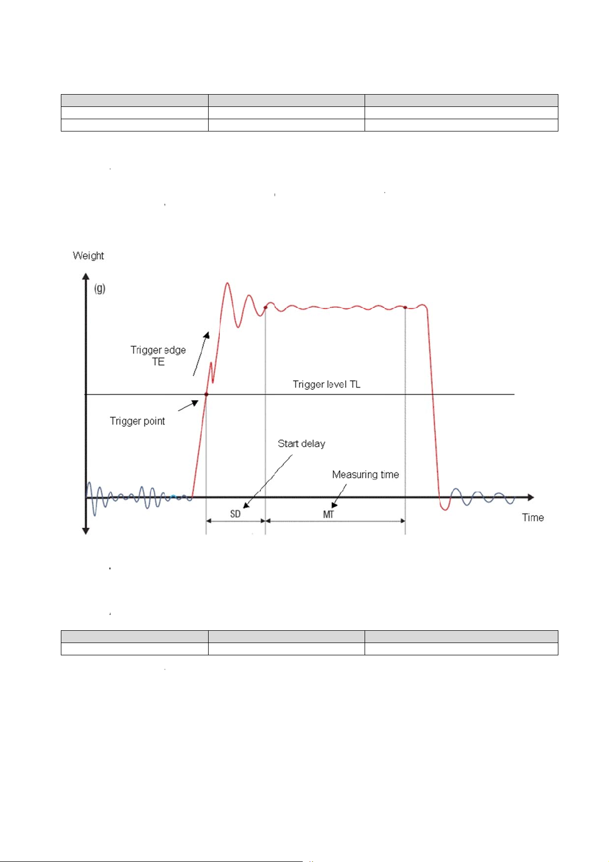
.
8.12.6. T
L
m
m
m
t
A
r
g
a
T
A
m
h
s
m
a
9
b
w
g
s
r
L
n
g
w
c
g
n
n
+
d
a
e
w
v
A+
e
o
a
b
y
o
v
m
h
r
m
m
c
S
e
u
c
l
m
e
e
9
0
d
1
f
9
a
This com
Master
In the exa
trigger co
Default set
Note:
trigger (Di
setting dis
ll t
L
and defines
(PC / SPS)
TL
TL 1000
ple a new
mands SD
ting: TL = 9
igger possi
ital input 0)
bles the tri
Trigger
a level for a
ends
easureme
nd TL).
999 [ = trig
ilities are al
ill be used
ger level.
evel
rising edge
Slave (LDU
T
t cycle woul
er level dis
ays availab
the trigger l
trigger on th
XX.X) resp
99999
OK
automatic
bled]
le in parallel
vel should
e measure
nds
lly start, if t
. If a softwa
e set to its
ent signal.
Requ
Set
e signal ex
e trigger (co
aixmum va
etting rang
Meaning
st: TL = 99
p: TL = 10
eeds 1000
mmand TR)
lue (TL = 99
: 0 to 9999
99
0
(e.g. 100,0
or a hardw
999). This
.
g;
re
Figure:
8.12.7. S
Master
This com
LDU 68
ime plot
(PC / SPS)
SA
and will sta
.1 & 68.2 Tec
of a typi
Send Tri
ends
t to auto-tra
nical Manual
al check
gered A
Slave (LDU
smit the m
Rev. 12 Ja
eigher c
erage Va
XX.X) resp
01.100
asurement
uary 2010
cle
lue auto
nds
alue of the
atically
Measure
urrent trigg
Meaning
ent value:
r cycle.
,100 d
Page 26 o
28
Page 27

9. Use in “Approved” Applications (LDU 68.1 only)
The term “approved” applies whenever the weighing application is intended to be used for “legal-for-trade”
weighing – that is, money will change hands according to the weight result. Such applications are bound by the
legal metrology regulations of the relevant governments around the World, but most countries will comply with
either the relevant EN’s (Euro Norms) or the relevant OIML (Organisation Internationale de Metrologie Legale)
recommendations.
The LDU 68.1 has been approved as a component for use in weighing systems according to OIML
recommendation R76, the highest performance level approved being Class III, 10 000 intervals(e) and 2x 4000
intervals. The approval Authority was the Danish Electronics, Light & Acoustics (DELTA), and the approval
certificate number was DK0199 – R76 – 10.04, dated 25.02.2010.
This approval will allow the use in approved weighing systems throughout Europe, and in many other countries
of the World. To achieve approval on a particular application, it will be necessary to satisfy the relevant
Governmental Trading Standards Authority that the requirements of the various rules and regulations have
been satisfied. This task is greatly simplified if the key components of the weighing system, namely the load
cells and the weighing indicator or digitizer, are already approved as “components”.
Usually, a discussion with the Weighing Equipment Approvals Officers at the relevant National Weights &
Measures Office will then reveal the extent of any pattern testing that may be necessary to ensure compliance.
Restrictions upon usage when in “Approved” applications
A number of performance restrictions must come into force. These restrictions are the number of display
divisions, which become limited to 10 000 divisions, and the sensitivity per display division, which becomes 1
μV per division. Once installed in the application, an “approved” application will require “stamping” by an Officer
of the relevant Governmental Trading Standards Department. This certifies the equipment or system as being
in accordance to the relevant regulations and within calibration limits.
The Traceable Access Code (TAC)
The user software must then provide a guard against improper access of the calibration commands (see the
“Calibration Commands” section). The LDU 68.1 digitizer features the “Traceable Access Code” or TAC method
of controlling the access to the calibration commands group. This means that a code is maintained within the
device, and is incremented whenever any change to any of the calibration commands is saved.
When performing the “stamping” test, the Trading Standards Officer will make a note of the TAC, and advise
the user that any change to this code which occurs prior to the regular re-inspection by the Trading Standards
Office, will result in legal prosecution of the user.
The user software is required as a condition of approval, to make the TAC available to the weight display
indicator or console, on demand.
LDU 68.1 & 68.2 Technical Manual, Rev. 12 January 2010
Page 27 of 28
Page 28
10. Updates – Firmware Download
For a software update the LDU xx.x amplifier has to be connected with a Windows PC via the serial interface
(4-wire connection; RS485/RS422 respective RS485/RS232 converter). The solder pads SW4 on the bottom
side of the PCB must be closed before switching on. After the download the solder pads must be opened again.
A download is accomplished with help of our program “PROG78”.
Firmware update for LDU xx.x series:
First all necessary files (LduDownload.exe, progXX.a20, lduXX.a20) have to be stored in same directory. The
firmware for LDU 68.x is stored in file lduXX.a20.
Close the solder pads SW 4 on the under side of PCB.
LDU XX.X is de-energized
Close solder pads SW4 on the bottom side (see chapter 5.1)
Switch on LDU xx.x
Start program “LduDownload”.
Press button “Load” and choose file ”lduXX.a20”.
Press button “Program”.
At message “Reset LDU before proceeding” switch the LDU XX.X off and on again and press the button
“OK”.
Download proceeds. – The end will be indicated with ”Programming OK “.
Switch off LDU XX.X .
Open solder pads SW 4
Now use a terminal program or DOP software for running a factory reset of the LDU XX.X by using the
command FD
Note: The command FD is TAC protected. You must issue the CE command with relevant TAC code prior to
the FD command else the FD command will fail.
FD Reset to Factory Default Settings
This command puts the LDU back to a known state. The data will be written to the EEPROM and the TAC will
be incremented by 1.
Note: All calibration and setup information will be lost by issuing this command!
Master (PC / SPS) sends Slave (LDU XX.X) responds Meaning
CE E+00017 (example)
CE 17 OK
FD 0 OK
Request: TAC counter CE17
Calibration sequence active
Factory default setting
WWW.FLINTEC.COM
LDU 68.1 & 68.2 Technical Manual, Rev. 12 January 2010
Page 28 of 28
 Loading...