

Page 1
Doc. No: 4-9131 Rev3
Date: 2008-12-10
Sign.: KN
Application Guidelines
for Weigh Modules type
52-18RS and 52-18SS
1
Page 2

Content
Page No
Brief product description 3
Principle of Rocking System 4
Principle of Sliding System 5
Pre assembled weigh modules/Function of aligning plate 6
Jacking device 6
Lift off protection 7
Overload protection 7
Dimensions 8
Data 8
2D CAD files 9
3D CAD files 9
Installation 10-11
Enclosures:
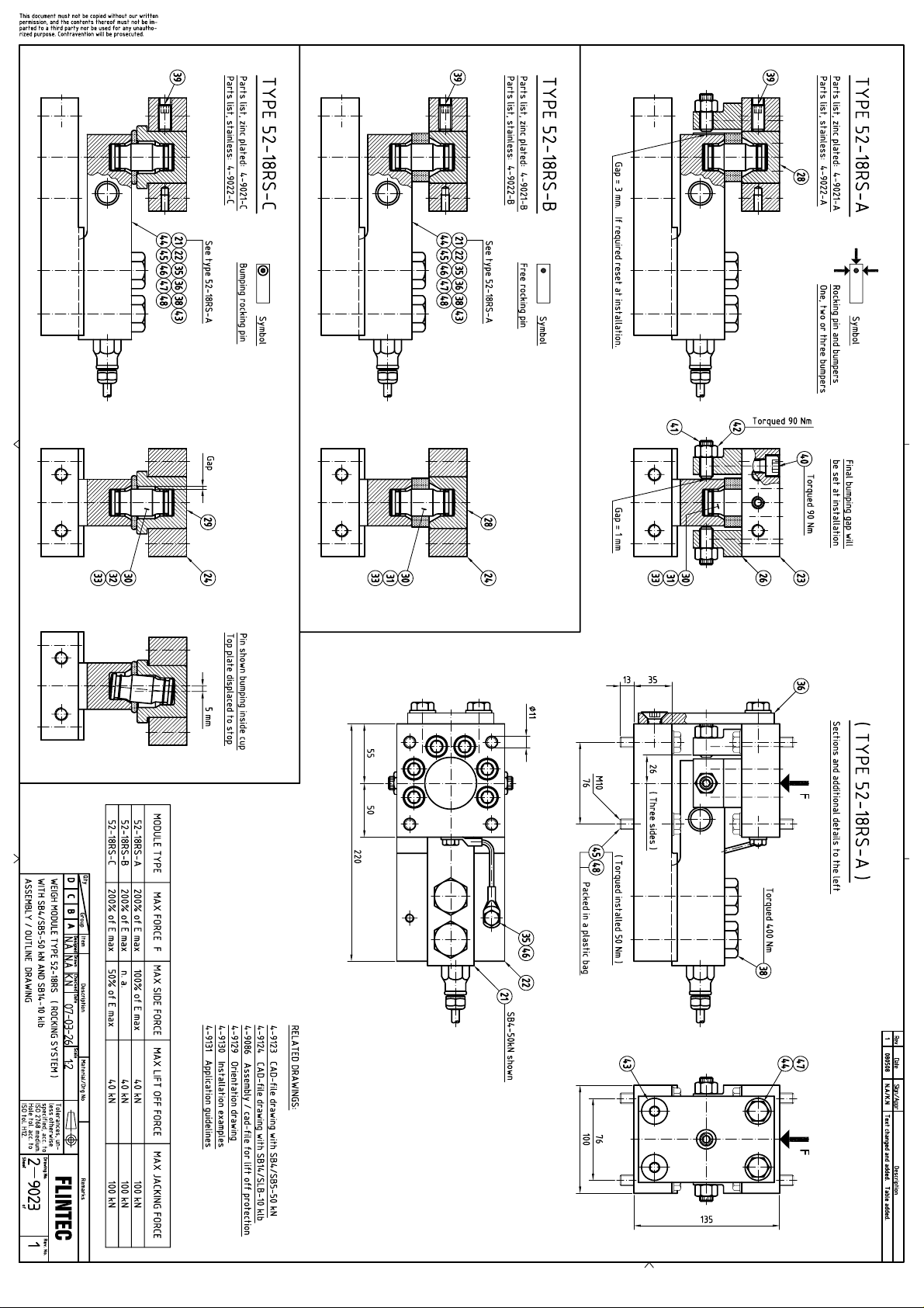
Drawing No 2-9023. Assembly drawing of Weigh Module 52-18RS-50kN (Rocking System)
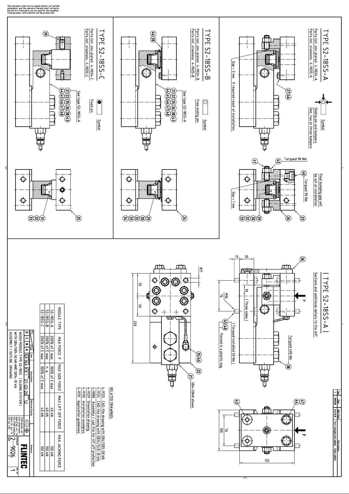
Drawing No 2-9026. Assembly drawing of Weigh Module 52-18SS-50kN (Sliding System)
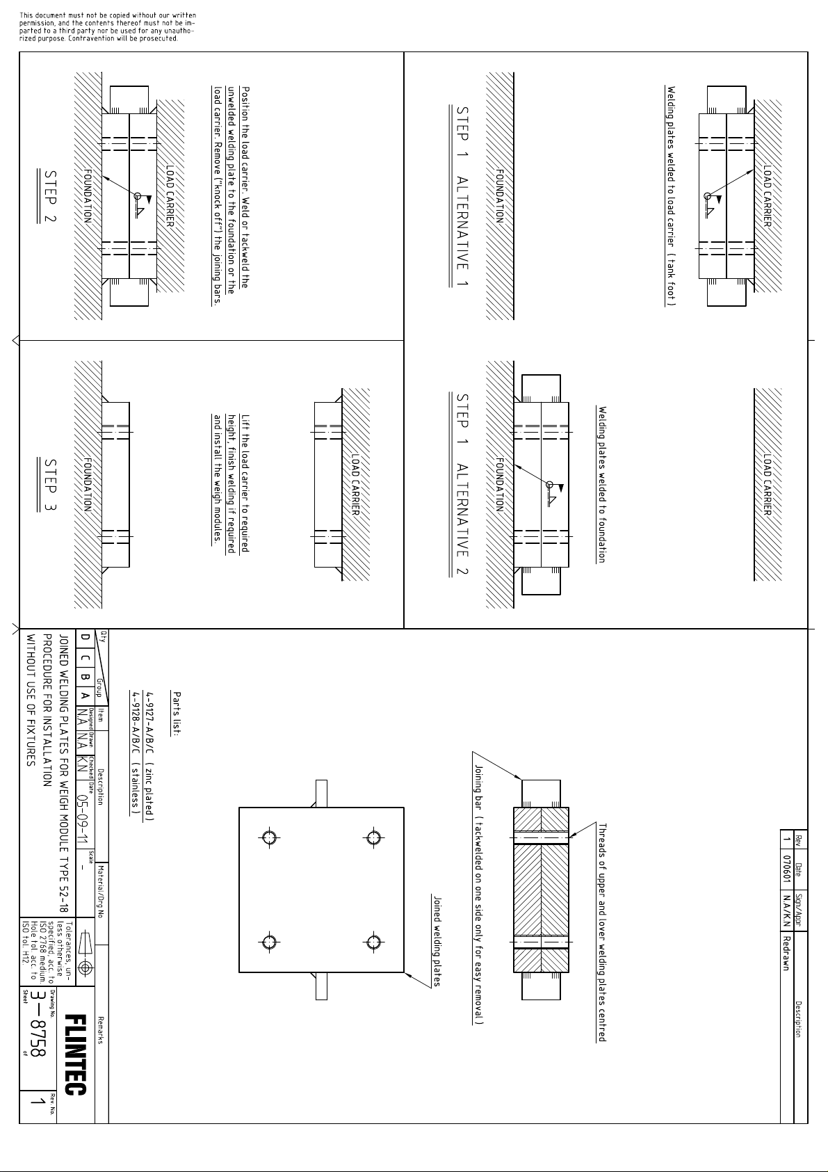
Drawing No 3-8758. Procedure for installation without use of welding fixtures.
2
Page 3
Brief Product Description
Type of application
52-18RS (Rocking System)
52-18SS (Sliding System)
Static load applications
X
X
Scales with agitator
1)
X
Scales with large temperature expansions
X
High resolution applications
X
1) Possible with close adjusted bumpers and special orientation.
Type 52-18 weigh modules are designed for load cells type SB4, SB5, SB14 and SLB and are available in 2 basic
versions, 52-18RS employing the Rocking System and 52-18SS employing the Sliding System.
The weigh modules are being delivered preassembled and centered with an Aligning Plate for easy installation.
Both versions have identical outer dimensions and utilize same mounting principles, but have somewhat different
features. Some features are overlapping and which version is the optimal choice depends on the actual
application.
The 52-18RS-C with its Rocking Load Introduction and Internal Bumping, is the first choice for static load
applications, because:
-It is easiest to install.
-All weigh modules in a scale are identical.
-Modules can be oriented freely in any direction.
-It is the most cost effective version.
However, this module is not suitable for tanks with agitators, which rotating movement might cause the scale to
oscillate, as it is standing on rockers.
For agitator applications, the 52-18SS, with Sliding Load Introduction and external bumping shall be used.
This module is also the choice when very large expansions due to temperature or other reasons are expected.
This module can tolerate side forces up to as much as 100% of rated load, whereas the 52-18RS-C is limited to
50%.
The selection guide below further illustrates when to use which module.
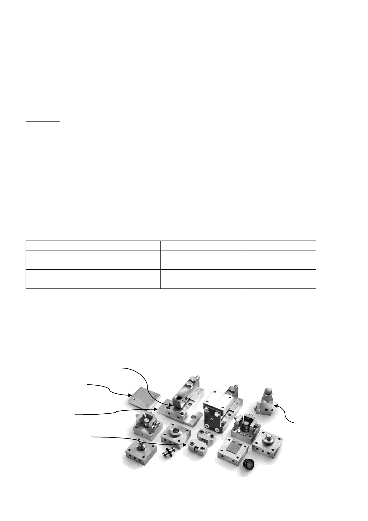
The 52-18 is a modularized weigh module which means that it is comes in a basic version, which can be fitted with
a number of options as required for the actual application:
Overload protection
Welding plates
Bolting plates
Jacking device
Lift off protection
3
Page 4
Principle of Rocking System
The rocking pin is “self centering”. The pin has relatively large radiuses (larger than ½ the pin height) and
therefore the rocker strives to stand straight up. With pins in vertical position, or near to vertical position,
possible horizontal forces between the load cells are zero, or very close to zero, which enhances repeatability and
thus the accuracy of the scale. The Rocking System is the most accurate load introduction system there is for
multi load cell scales.
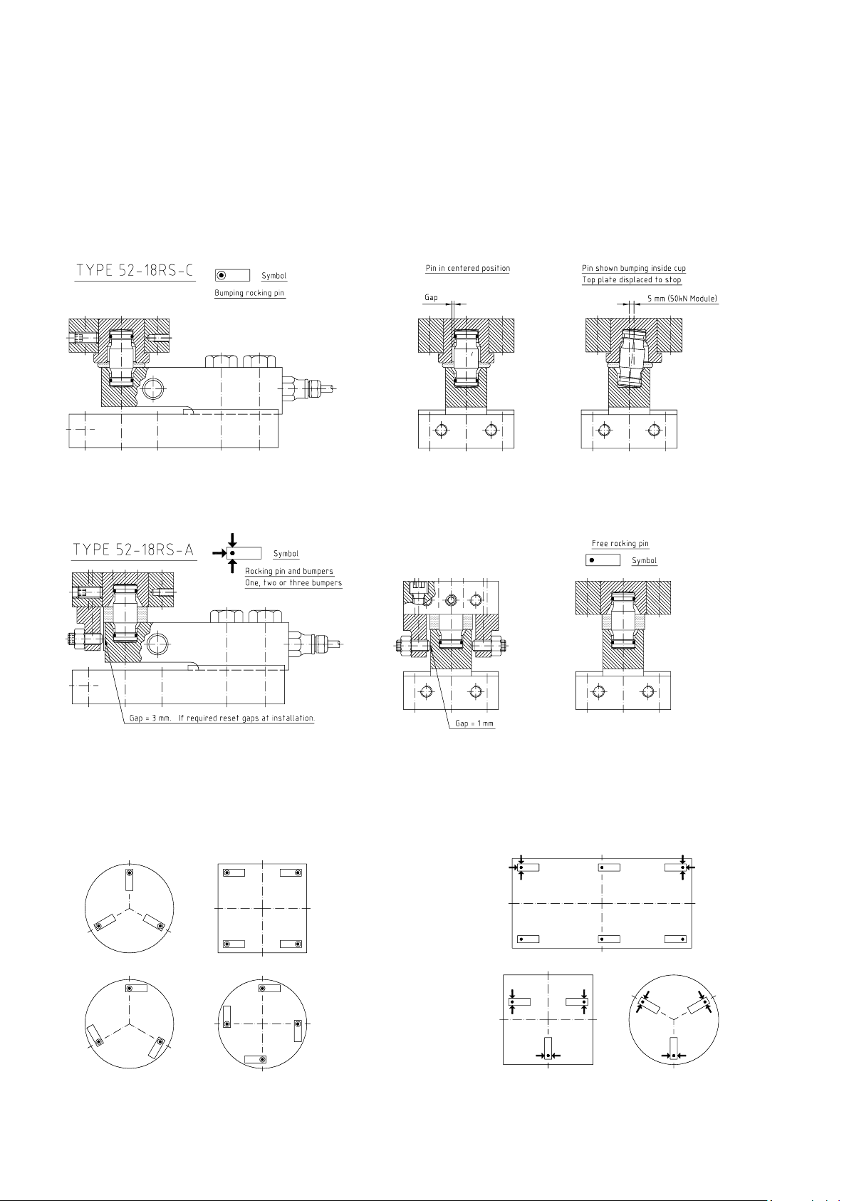
The Rocking System comes in 2 versions. With rocking pin bumping internally in the loading cup (figure 1),
respectively with regular rocking pins and external bumpers (figure 2).
Figure1. Type 52-18RS-C. Module with pin bumping internally in loading cup.
Figure 2. Type 52-18RS-A. Module with external bumpers.
Figures 3 and 4 below show a few examples of how to orient the Rocking System weigh modules.
Figure 3. Orientation with internally bumping pins. Figure 4. Orientation with external bumpers.
4
Page 5
Principle of Sliding System
The Sliding System is based on loading pins fitted with Teflon (PTFE) sliding plates sliding against Stainless Steel
Sheets with very smooth surface (Surface finish 2B). This surface combination gives a very low friction coefficient
(typ < 5-6%). It allows length changes of the load carrier to take place, without causing any considerable
horizontal forces between the load cells.
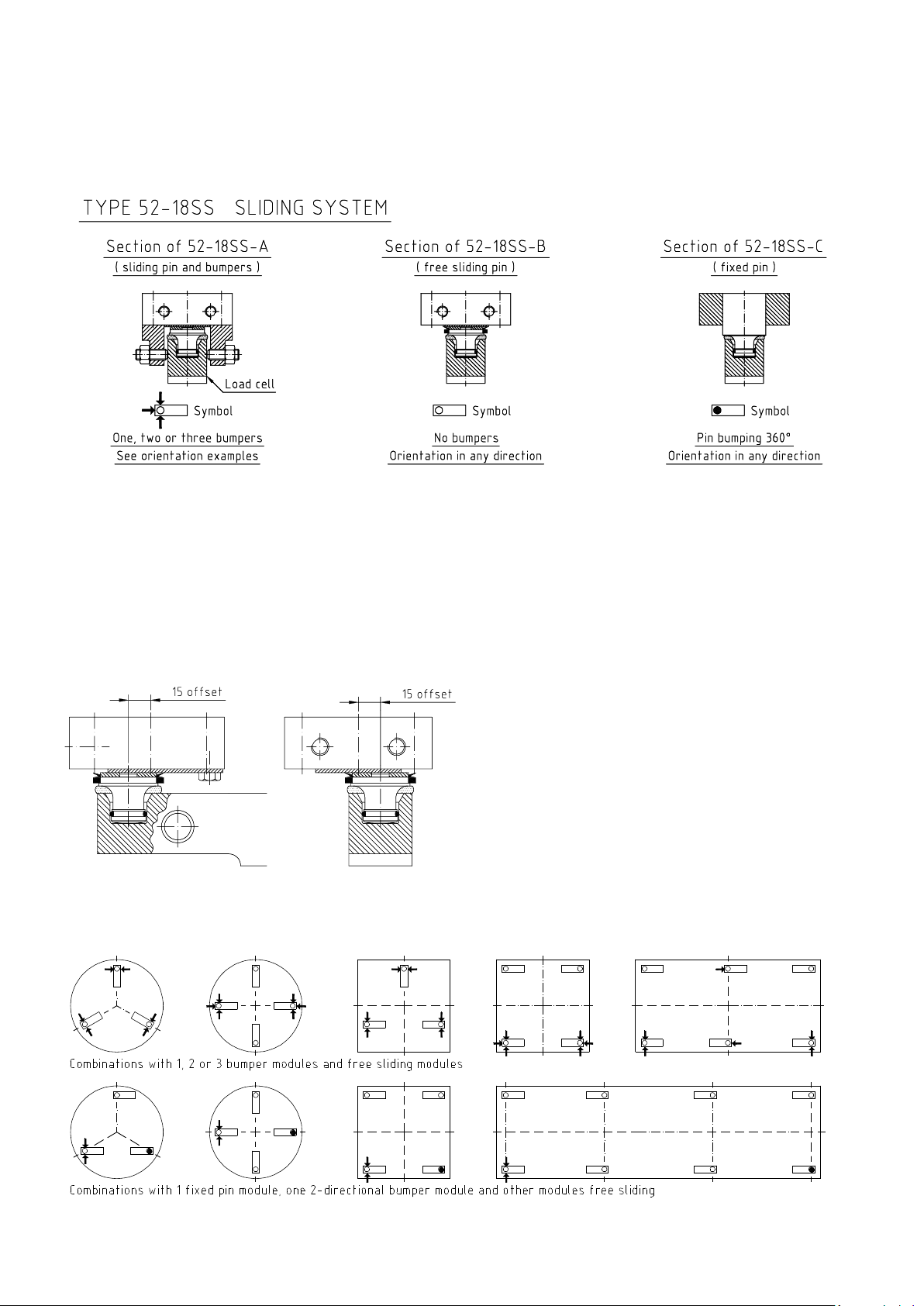
Figure 5. Type 52-18SS Variants with bumpers, without bumpers, resp. with fixed pin.
Movement of the load carrier is restricted by bumpers acting against the loading end of the load cell.
A module can have 1, 2 or 3 bumpers, or no bumpers at all. It can also have a “fixed loading pin” which acts as a
360˚ bumper.
These variants make possible a large number of bumper combinations. Which variant is the optimal choice
depends on the actual application. One combination which works well for most types of load carriers is: “one
fixed pin module, one module with 2 bumpers and all other weigh modules free sliding”.
The Sliding System is perfect for applications which
exhibit very large temperature expansions.
Figure 6 illustrates that that the top plate of a 50kN
module can be positioned offset, by as much as
15 mm and still function. This also means that the
centering of the sliding modules during installation is
not very critical.
Figure 6. Top plate of -50kN module, shown offset by 15 mm.
Figure 7. This figure shows some typical examples on how to orient the Sliding System weigh modules.
5
Page 6
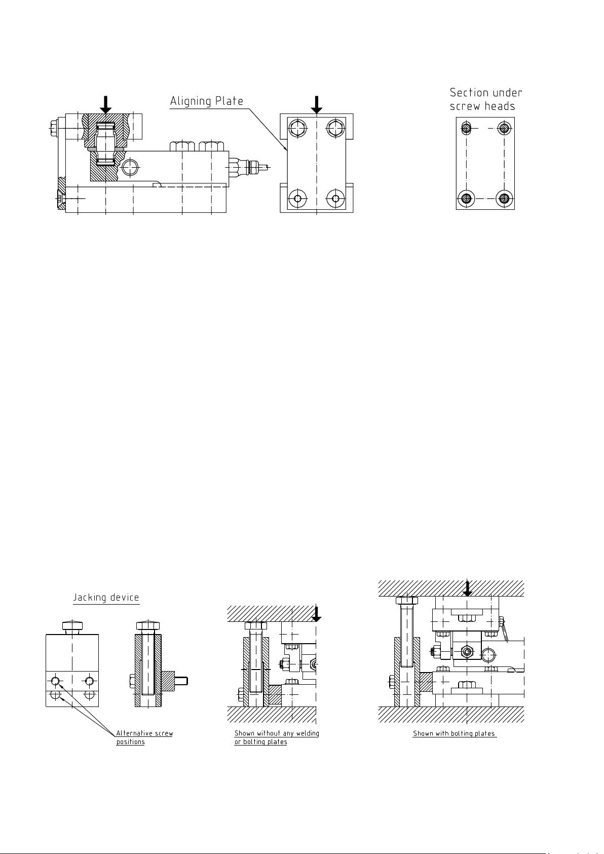
Preassembled Weigh Module/function of Aligning Plate
The weigh modules are delivered preassembled and centered with an Aligning Plate, for easy installation.
Figure 8
Figure 8 shows the preassembled weigh module 52-18RS-C with internally bumping rocking pin.
The lower 2 screws in the aligning plate are both conically recessed and thus these screws hold the plate in exact
aligned position in relation to the base plate. The upper 2 screws in turn hold the top plate in centered position
relative to the base plate.
One of the upper 2 holes in the aligning plate is vertically oblong with tight fit to the screw, while the other hole
has large clearance to the screw. This allows the top plate to adjust to the tank foot, in case the foot is not exactly
parallel to the foundation plate. The upper 2 screws are therefore just slightly torqued, in order to allow such
angular movement during installation.
Jacking Device
As an option a jacking device is available to lift the load carrier, in case a load cell needs to be replaced.
See figure 9. The jacking device is secured to the base plate with 2 screws which fit the 2 holes earlier used for
the above described aligning plate. The device has alternative pairs of holes to be used with resp. without welding
or bolting plates.
Any other jacking device that fits between load carrier and foundation can, of course, also be used.
Figure 9 Figure 10 Figure 11
6
Page 7
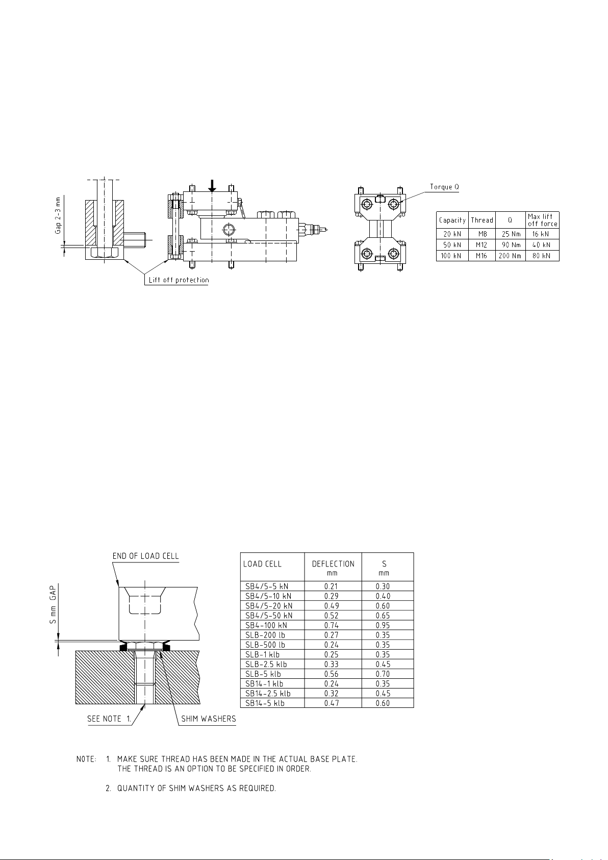
Lift off protection.
An optional lift off protection can be fitted after the installation of the weigh module. It utilizes the same holes
which, before installation, were used with the alignment plate to hold the module together.
In most indoor applications the tanks or hoppers never see any wind forces or other side forces, which could
cause lift off. Lift off protection should therefore only be added when required.
The lift off bolt has large clearance to the upper and lower brackets which allows the rocking or sliding motion of
the module without interference. The lift off gap can be set by rotating the nut on the screw prior to mounting.
Figure 12.
Overload protection
As yet another option, the weigh modules can be fitted with an overload stop, which protects the load cell in case
of an overload. The overload stop is simply the head of a hex head screw, which stops the down movement of the
loading end of the cell. Thanks to the relatively large deflection of the shear beam, the gap between the cell and
the screw head is easy to set by inserting shim washers under the head. The table below shows recommended
gaps which are selected to be ca 30 – 40 % more than the deflection of the cell at nominal load. The actual gap
can be measured by using a feeler guage. If the load cell is to be utilized to less than nominal load, the gap can
preferably be reduced in proportion. With overload stop fitted, the cell will be protected to at least 5 times
nominal load.
A rubber V-ring prevents dirt from entering the gap.
7
Figure 13.
Page 8
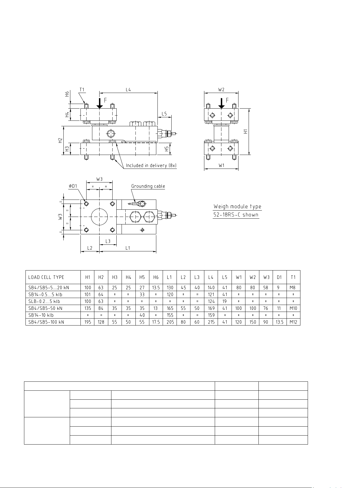
Dimensions
WEIGH MODULE TYPES
MAX FORCE F
MAX SIDE FORCE
52-18RS-A
With Rocking pin and bumpers
200% of Emax
100% of Emax
Rocking System
52-18RS-B
With free rocking pin
200% of Emax
n. a.
52-18RS-C
With bumping rocking pin
200% of Emax
50% of Emax
52-18SS-A
With sliding pin and bumpers
200% of Emax
100% of Emax
Sliding System
52-18SS-B
With free sliding pin
200% of Emax
n. a.
52-18SS-C
With fixed pin
200% of Emax
100% of Emax
Below is an Outline Drawing which also can be found on the 52-18 Data Sheet. It covers all capacities of 52-18 in
their basic form, i.e. without liftoff protection, welding plates or bolting plates.
A combined Assembly/Outline drawing for each individual capacity, which is more detailed, is available on
request. As an example, this drawing for the 50kN capacity weigh module, can found in the enclosures section.
Same drawing, for the actual capacity weigh module, is always included in the delivery.
Figure 14.
Data
Emax= Maximum load cell capacity
For Max lift off force data, see section “Lift off protection”.
8
Page 9
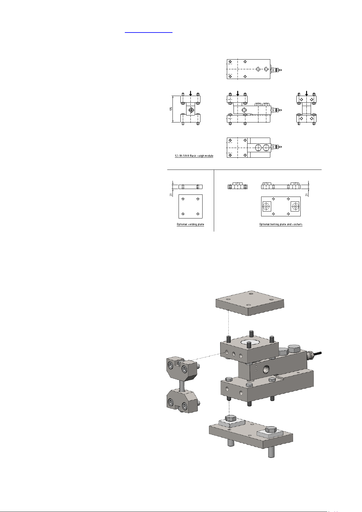
CAD files, for copying and pasting into customer’s own application drawings, are available on request or by
downloading from Flintec web page www.flintec.com. From these files the applications engineer can select his
preferred combination of basic unit plus options, to copy and paste into his application drawing.
2D CAD files
Figure 15. Figure shows 2D views of the 50 kN module and
optional welding and bolting plates.
…………………………………………………………………………………………………………………………………………………………………………………
3D CAD files
Figure16. Figure shows a 3D model of the 50 kN module
with options.
9
Page 10
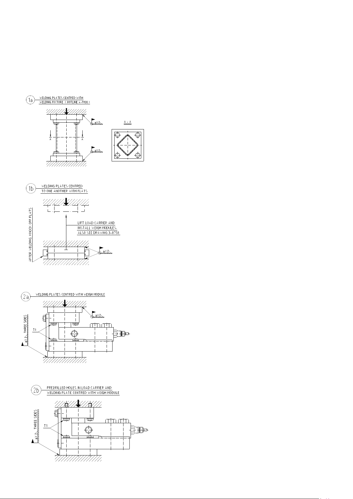
Installation
A large number of installation methods are available.
For large tanks and hoppers it is usually impossible to position mounting holes in load carrier resp. in the
foundation structure accurately enough to allow insertion of all mounting screws. The use of Welding Plates or
Bolting Plates, the latter having pre drilled extra large mounting holes, are therefore convenient methods to solve
this problem. Some of these alternatives are shown below.
-Figure 1a shows how welding plates on top and on bottom can be
accurately installed using a welding fixture.
-Figure 1b shows how same welding plates can be accurately installed
without the use of a welding fixture.
The welding plates, in this case, are delivered centered to one another with
a pair of “knock-off flats”. A requirement for this alternative is that the
load carrier can be lowered down deep enough to apply tack welds to hold
each of the plates in position. When this has been done, the flats are to be
knocked off, load carrier lifted and welding finalized.
Enclosure 3-8758 describes this method more in detail.
-Figure 2a shows a case where the weigh module itself acts as a fixture
for holding the welding plates in position.
Note that the welding plates are slightly bigger than the top resp. the
bottom plates. This makes it easy to hold a piece of sheet metal against
the welding plate to protect the weigh module from weld splashes.
When welding, make sure that the ground cable of the welding machine
is connected to the same side at which the welding is done, so that no
current flows through the load cell. Load cell cable should preferably
not be connected in the summing box during welding.
-Figure 2b illustrates a case where the load carrier has been
prepared with mounting holes from factory.
The weigh module holds the welding plate in position against the
foundation, ready for welding.
This method opens the possibility of pre-installing the modules to
the load carrier in the factory and deliver, ready for the final
welding operation on site. Cables, summing boxes etc. can in this
case preferably also be pre installed “on board” the load carrier.
10
Page 11
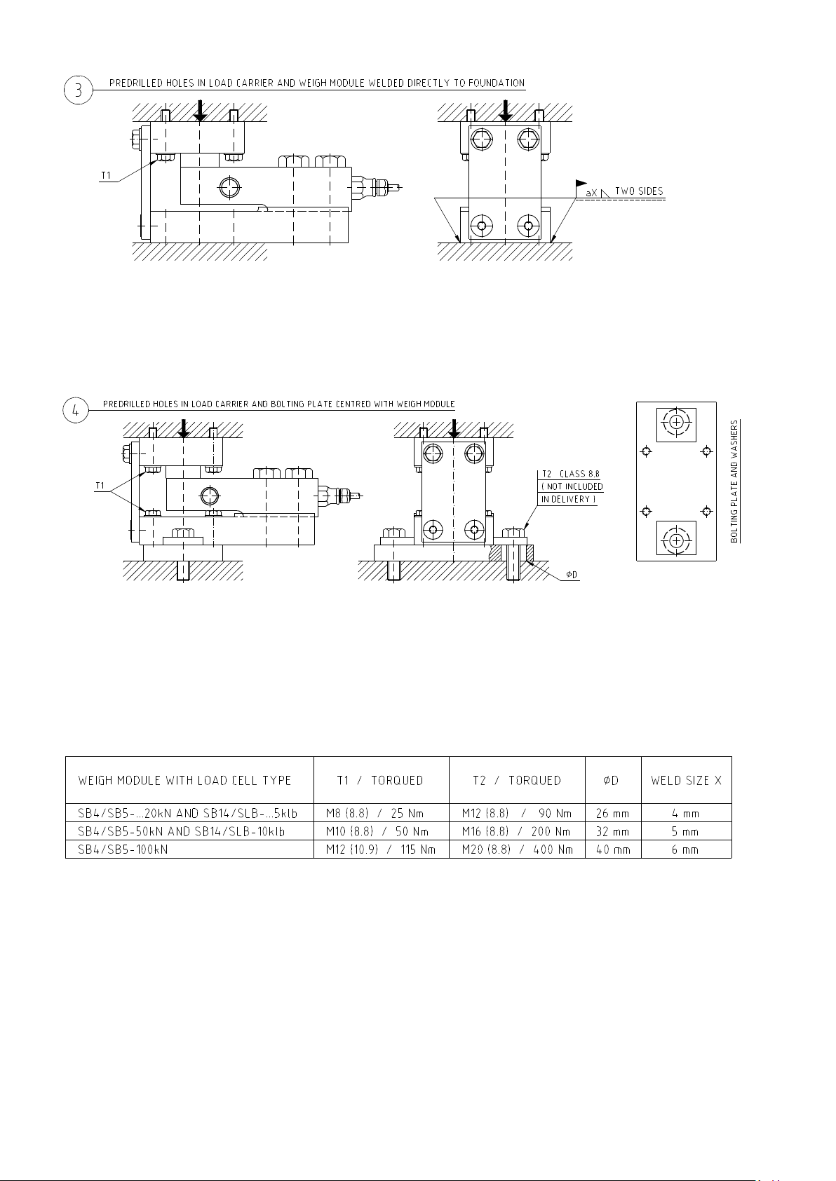
-Figure 3 is similar to 2b, but in this case, the base plate of the weigh module is welded directly to the foundation
plate without any welding plate in between.
-Figure 4 shows a case with pre-drilled mounting holes both in load carrier and in foundation and where the
weigh module has been fitted with a bolting plate on bottom side. The bolting plate has extra large clearance
holes for the mounting bolts, which can compensate for a considerable misplacement of the mounting holes.
With bolting plates both on top and bottom the compensation range is doubled.
-The above table shows weld sizes and torques required to withstand the max specified side forces of a weigh
module. For applications with no, or very small, side forces, these values of course can be selected differently.
11
Page 12
Page 13
Page 14
 Loading...