

Page 1

Type 52-28 Weigh Module
A
PPPPLLIICCAATTIIOONN
A
G
UUIIDDEELLIINNEES
G
S
Flintec GmbH
Bemannsbruch 9
DE 74909 Meckesheim
GERMANY
www.flintec.com
Page 2

Content:
1. Brief Module Description ................................................................................................................................. 3
2. Pre-assembled Weigh Module ........................................................................................................................ 3
3. Lift Off Protection and Jacking Device ............................................................................................................ 4
4. Overload Protection ........................................................................................................................................ 4
5. Dimensions and Check Link Orientation ......................................................................................................... 5
6. Available Accessoires ..................................................................................................................................... 6
7. Installation ....................................................................................................................................................... 6
Addendum: Joined Welding Plates.......................................................................................................................... 8
52-28 Application Guidlines, Rev. 1.00 September 2012
Page 2 of 8
Page 3
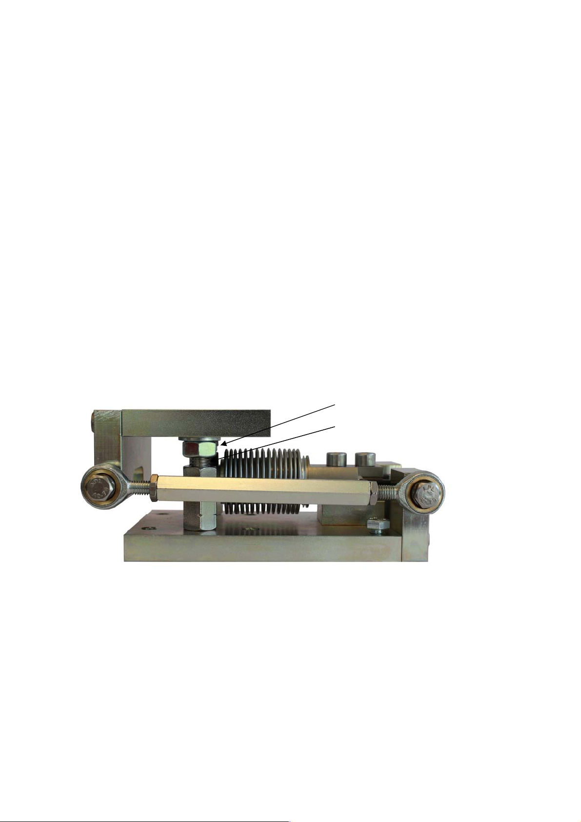
1. Brief Module Description
Fig. 1:
Pre-assembled
Type 52
-
28 W
e
igh Module
The Type 52-28 Weigh Module is especially designed for type SB8 and SB6 load cells. It is a weigh module with
integrated check link and lift-off protection, which perfectly suits hopper and tank weighing applications. An
adjustable overload protection and an integrated jacking device complete the technical features.
Type 52-28 prevents unwanted forces from affecting the load cell performance and it eliminates oscillations
caused by slow moving agitators. In a scale you can apply modules with check link and without check link (see
chapter 5: Check Link Orientation).
Standard module:
• Steel, zinc plated (S355JR, material no. 1.0045), with or without check link
Optional version:
• Stainless steel (material no.1.4301), with or without check link
Type 52-28 is very easy to install. If delivered with new load cells the module will be shipped completely preassembled and ready for installation. M8 mounting screws and washers for connecting the module with a
foundation plate or the load carrier are part of the standard delivery.
The connection between module and foundation/load carrier can be done by screwing or welding. Welding
instead of bolting is a practical alternative eliminating problems of getting holes on top and bottom lined up. The
combination of welding and bolting is also possible. A suitable welding plate is an available acccessory.
2. Pre-assembled Weigh Module
If delivered with new load cells the module will be shipped completely pre-assembled and ready for installation.
The integrated jacking device (2x M12 nut) is used as a transport lock for the upper load plate.
2x M12 nut (Jacking device)
2x M12 screw (Lift-off protection)
with locked load late (the ground strap which is not
shown is part of the standard delivery)
52-28 Application Guidlines, Rev. 1.00 September 2012
Page 3 of 8
Page 4
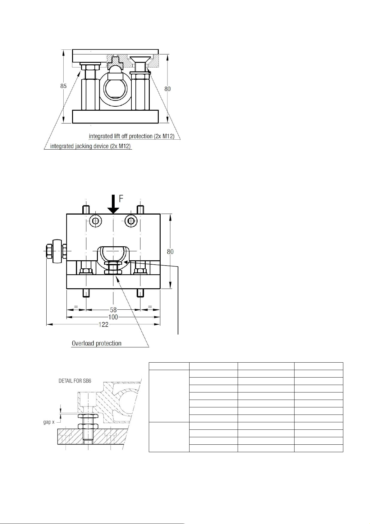
3. Lift Off Protection and Jacking Device
Fig.
2:
Lift off protection
and
jacking device
Fig.
3:
Overload protection
Load cell
Max capacity
Deflection
[mm]
Gap x [mm]
Table
1:
Gap settings for the overload protection
Gap
x
Max. lift off force: 5 kN (510 kg). The gap of is preset.
The jacking device simplifies future maintenance.
Max. jacking force: 5 kN (510 kg)
Important: Both nuts of the jacking device are used as a
transport lock. After the installation and prior to the
commissioning these nuts have to be unlocked.
4. Overload Protection
Each weigh module is equipped with a preset overload
protection, which protects the load cell in case of an
overload.
The overload stop is simply the head of a hex head
screw, which stops the down movement of the
loading end of the cell. Thanks to the relatively large
deflection of SB8 respective SB6, the gap x between
the cell and the screw head is easy to set. The table
below shows the recommended gaps which are
selected to be ca 30 – 40 % more than the deflection of
the cell at nominal load. The actual gap
can be measured by using a feeler gauge. If the load
cell is to be utilized to less than nominal load, the gap
can preferably be reduced in proportion. With overload
stop fitted, the cell will be protected to at least 5 times
nominal load.
52-28 Application Guidlines, Rev. 1.00 September 2012
SB8 10kg 0.29 0.35
20kg 0.30 0.35
50kg 0.23 0.30
100kg 0.30 0.40
200kg 0.38 0.45
250kg 0.87 1.00
500kg 1.25 1.50
SB6 20kg 0.21 0.25
50kg 0.30 0.40
1kN (102 kg) 0.26 0.35
2kN (204 kg) 0.36 0.45
Page 4 of 8
Page 5
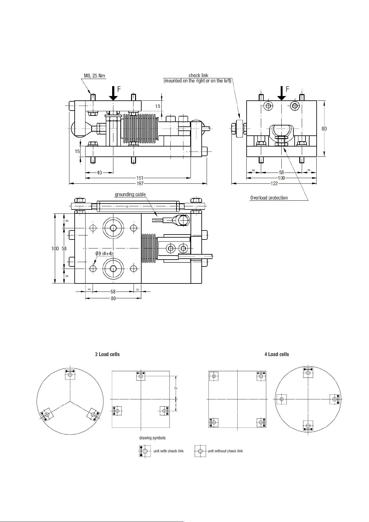
5. Dimensions and Check Link Orientation
Fig. 4: Weigh
m
odule with
c
heck
l
ink
Fig.
5: Check
l
ink orient
ation
The movement of the load carrier is restricted by adjustable check links with rod ends. During the installation
they have to be adjusted for minimum tension. This assures an optimal accuracy and the best repeatability.
Each check link is designed for a max. force of 5 kN (510 kg).
Please take care for the correct module orientation when installing the weigh modules.
52-28 Application Guidlines, Rev. 1.00 September 2012
Page 5 of 8
Page 6
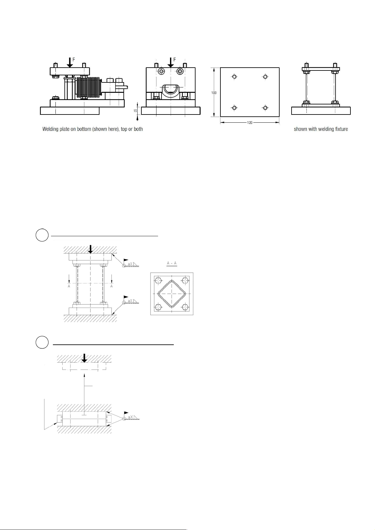
6. Available Accessoires
Fig. 6:
Welding plate and welding fixture
7. Installation
For tanks and hoppers it is usually impossible to position mounting holes in load carrier resp. in the
foundation structure accurately enough to allow insertion of all mounting screws. The use of welding plates or
bolting plates, the latter having pre drilled extra large mounting holes, are therefore convenient methods to solve
this problem. Some of these alternatives are shown below.
Welding plates centred with welding fixture
1a
Figure 1a shows how welding plates on top and on
bottom can be accurately installed using a welding
fixture.
Welding plates centred to one another with flats
1b
Remove
flats after
welding
Lift load carrier and install
weigh modules
Figure 1b shows how same welding plates can be
accurately installed without the use of a welding
fixture. The welding plates, in this case, are
delivered centered to one another with a pair of
“knock-off flats”. A requirement for this alternative is
that the load carrier can be lowered down deep
enough to apply tack welds to hold each of the
plates in position. When this has been done, the
flats are to be knocked off, load carrier lifted and
welding finalized (see addendum).
52-28 Application Guidlines, Rev. 1.00 September 2012
Page 6 of 8
Page 7
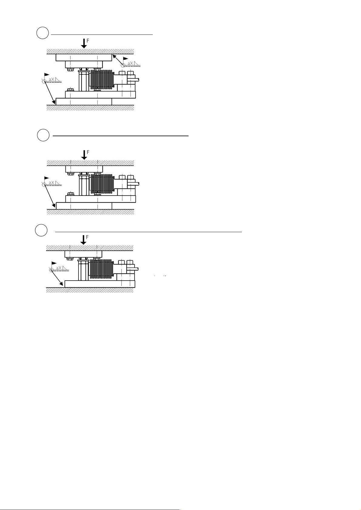
Figure 2a shows a case where the weigh module
with weigh module
Welding plates centred with weigh module
2a
itself acts as a fixture for holding the welding plates
in position. Note that the welding plates are slightly
bigger than the top resp. the bottom plates. This
makes it easy to hold a piece of sheet metal against
the welding plate to protect the weigh module from
weld splashes.
Weld on
three sides
When welding, make sure that the ground cable of
the welding machine is connected to the same side
at which the welding is done, so that no current
flows through the load cell. Load cell cable should
preferably not be connected in the summing box
during welding.
Predrilled holes in load carrier and welding plate centred
2b
Figure 2b illustrates a case where the load carrier
has been prepared with mounting holes from
factory. The weigh module holds the welding plate
in position against the foundation, ready for welding.
This method opens the possibility of pre-installing
the modules to the load carrier in the factory and
deliver, ready for the final welding operation on site.
Weld on
three sides
Predrilled holes in load carrier and welding plate welded directly to foundation
3
Weld on
three sides
Figure 3 is similar to 2b, but in this case, the base
plate of the weigh module is welded directly to the
foundation plate without any welding plate in
between.
52-28 Application Guidlines, Rev. 1.00 September 2012
Page 7 of 8
Page 8
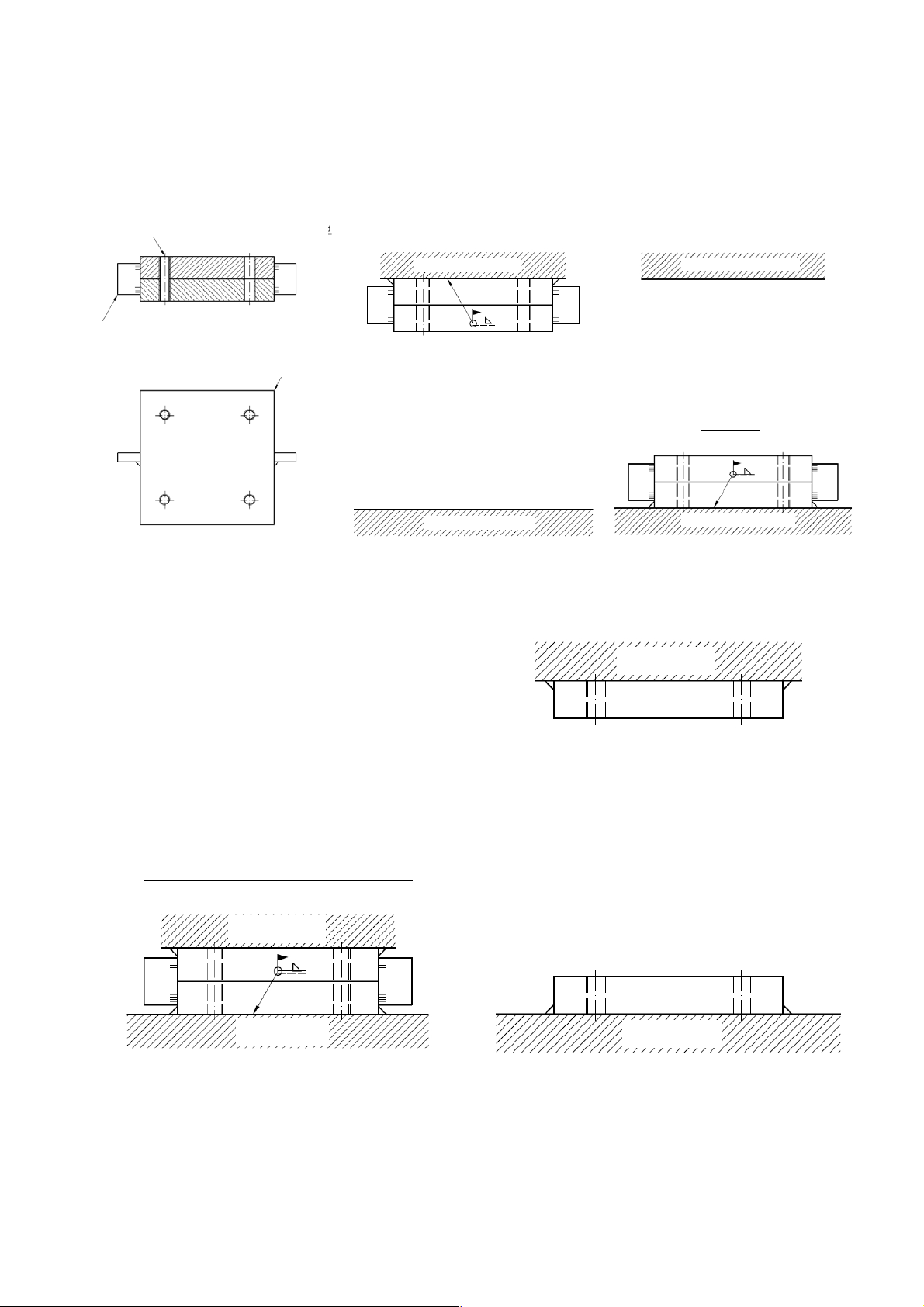
Addendum: Joined Welding Plates
Preparation
: S
tep 1 Alternative 1
S
tep 1 Alternative 2:
S
tep 2: S
tep 3:
•
•
:
Threads of upper and lower welding
plated centred
Joining bar (for easy removal tackwelded on
one side only)
Joined welding plates
Load carrier
Welding plates welded to load carrier
(e.g. tank foot)
Foundation
Load carrier
Welding plates welded to
foundation
Foundation
Position the load carrier
• Weld or tackweld the unwelded welding plate to
the foundation or the load carrier
• Remove the joining bar
Load carrier
Foundation
Load carrier
Lift the load carrier to the required height
• Finish welding, if required
• Install the weigh modules
Foundation
www.flintec.com
52-28 Application Guidlines, Rev. 1.00 September 2012
Page 8 of 8
 Loading...