


Weight Indicator
FT-11(D)
Technical Manual
For FT-11 Firmware Version 2.13 and higher For FT-11D Firmware Version 2.06 and higher
Flintec GmbH Bemannsbruch 9 74909 Meckesheim GERMANY www.flintec.com
Table of Contents:
1. |
Safety Instructions ..................................................................................................................................... |
4 |
|
2. |
Declaration of Conformity.......................................................................................................................... |
5 |
|
3. |
Overview...................................................................................................................................................... |
6 |
|
3.1 |
Key Features............................................................................................................................................. |
6 |
|
3.2 |
Available Options and Accessoires........................................................................................................... |
6 |
|
3.3 |
Technical Specifications............................................................................................................................ |
7 |
|
3.4 |
Housing Dimensions ................................................................................................................................. |
8 |
|
3.4.1 |
Desk Type Housing ........................................................................................................................................... |
8 |
|
3.4.2 |
Stainless Steel Housing .................................................................................................................................... |
8 |
|
3.4.3 |
Panel Type Housing (for FT-11 only) ................................................................................................................ |
9 |
|
4. |
Installation and Commissioning ............................................................................................................. |
10 |
|
4.1 |
Mechanical Installation............................................................................................................................ |
10 |
|
4.1.1. |
Jumpers........................................................................................................................................................... |
10 |
|
4.2. |
Electrical Connections............................................................................................................................. |
10 |
|
4.2.1. |
Power Supply and Grounding.......................................................................................................................... |
10 |
|
4.2.2. |
Standard Load Cell Connection (for FT-11 only) ............................................................................................. |
11 |
|
4.2.3. |
Digital Load Cell Connection (for FT-11D only) ............................................................................................... |
11 |
|
4.3. |
Commissioning........................................................................................................................................ |
11 |
|
5. |
Front Panel and Keypad........................................................................................................................... |
12 |
|
5.1. |
Weight Display and Status LEDs ............................................................................................................ |
12 |
|
5.2. |
Keypad .................................................................................................................................................... |
13 |
|
5.3. |
Key lock................................................................................................................................................... |
13 |
|
6. |
Setup and Calibration............................................................................................................................... |
14 |
|
6.1. |
Basics...................................................................................................................................................... |
14 |
|
6.1.1. |
Basic Setup Keys on the Frontplate ................................................................................................................ |
14 |
|
6.1.2. |
Entering the Setup and Calibration Menu........................................................................................................ |
14 |
|
6.1.3. |
Exiting the Setup and Calibration Menu .......................................................................................................... |
14 |
|
6.2. |
Defining the Digital Load cells (for FT-11D only) .................................................................................... |
15 |
|
6.2.1. |
Digital Load Cell Addressing ........................................................................................................................... |
15 |
|
6.2.2. |
Eccentricity Adjustment ................................................................................................................................... |
16 |
|
6.3. |
Configuration Parameters ....................................................................................................................... |
17 |
|
6.4. |
Scale Parameters.................................................................................................................................... |
17 |
|
6.5. |
Scale Calibration ..................................................................................................................................... |
19 |
|
7. |
Alibi Memory and Legal Metrological Records ..................................................................................... |
21 |
|
8. |
Communication......................................................................................................................................... |
22 |
|
8.1. |
Overview about Communication ............................................................................................................. |
22 |
|
8.2. |
Serial Interface and Printer ..................................................................................................................... |
22 |
|
8.2.1. |
Standard Serial Interface Connector (RS232C) .............................................................................................. |
22 |
|
8.2.2. |
Optional Serial Interface Connector (RS232C, RS485, 20 mA TTY)............................................................... |
22 |
|
8.2.3. |
Continuous Output Mode ................................................................................................................................ |
23 |
|
8.2.4. |
Host Mode (for FT-11 only) ............................................................................................................................. |
23 |
|
8.2.5. |
Print Mode ....................................................................................................................................................... |
23 |
|
8.2.6. |
Setup............................................................................................................................................................... |
24 |
|
8.3. |
Ethernet Option (for FT-11 only) ............................................................................................................. |
26 |
|
8.3.1. |
Electrical Connections..................................................................................................................................... |
26 |
|
8.3.2. |
Setup............................................................................................................................................................... |
26 |
|
8.3.3. |
Data Structure ................................................................................................................................................. |
28 |
|
8.4. |
Profibus Option (for FT-11 only).............................................................................................................. |
29 |
|
8.4.1. |
Electrical Connections..................................................................................................................................... |
29 |
|
8.4.2. |
Setup............................................................................................................................................................... |
29 |
|
8.4.3. |
Data Structure ................................................................................................................................................. |
29 |
|
FT-11(D) Technical Manual, Rev. 1.35 November 2010 |
Page 2 of 52 |
8.5. ProfiNet Option (for FT-11 only).............................................................................................................. |
30 |
||
8.5.1. |
Electrical Connections..................................................................................................................................... |
30 |
|
8.5.2. |
Setup............................................................................................................................................................... |
30 |
|
8.5.3. |
Data Structure ................................................................................................................................................. |
30 |
|
8.6. CANopen Option (for FT-11 only) ........................................................................................................... |
31 |
||
8.6.1. |
Electrical Connections..................................................................................................................................... |
31 |
|
8.6.2. |
Setup............................................................................................................................................................... |
31 |
|
8.6.3. |
Data Structure ................................................................................................................................................. |
31 |
|
9. |
Other I/O Options...................................................................................................................................... |
32 |
|
9.1. Analogue Output Option (for FT-11 only)................................................................................................ |
32 |
||
9.1.1. |
Electrical Connections..................................................................................................................................... |
32 |
|
9.1.2. |
Setup............................................................................................................................................................... |
32 |
|
9.2. |
Digital I/O Option..................................................................................................................................... |
33 |
|
9.2.1. |
Electrical Connections..................................................................................................................................... |
33 |
|
9.2.2. |
Setup............................................................................................................................................................... |
33 |
|
9.2.3. |
Entering Setpoints ........................................................................................................................................... |
34 |
|
9.3. |
Binary Output Option............................................................................................................................... |
34 |
|
10. |
Diagnostics ............................................................................................................................................... |
35 |
|
Appendix 1: Setup and Calibration Menus ...................................................................................................... |
36 |
||
Appendix 2: Continues Output Mode Data Structure ..................................................................................... |
38 |
||
Appendix 3: Host Mode Data Structure............................................................................................................ |
39 |
||
Appendix 4: Modbus RTU Data Structure........................................................................................................ |
42 |
||
Appendix 5: Profibus DP / ProfiNet Data Structure (FT-11 only)................................................................... |
45 |
||
Appendix 6: CANopen Data Structure (for FT-11 only) .................................................................................. |
47 |
||
Appendix 7: Error Table..................................................................................................................................... |
49 |
||
Appendix 8: Parameter’s Default Table............................................................................................................ |
50 |
||
Appendix 9: Calibration Table........................................................................................................................... |
52 |
||
FT-11(D) Technical Manual, Rev. 1.35 November 2010 |
Page 3 of 52 |

RIGHTS AND LIABILITIES
All rights reserved.
No part of this publication may be reproduced, stored in a retrieval system, or transmitted in any form or by any means, mechanical, photocopying, recording, or otherwise, without the prior written permission of Flintec GmbH
No patent liability is assumed with respect to the use of the information contained herein. While every precaution has been taken in the preparation of this book, FLINTEC assumes no responsibility for errors or omissions. Neither is any liability assumed for damages resulting from the use of the information contained herein.
The information herein is believed to be both accurate and reliable. FLINTEC, however, would be obliged to be informed if any errors occur. FLINTEC cannot accept any liability for direct or indirect damages resulting from the use of this manual.
FLINTEC reserves the right to revise this manual and alter its content without notification at any time.
Neither FLINTEC nor its affiliates shall be liable to the purchaser of this product or third parties for damages, losses, costs, or expenses incurred by purchaser or third parties as a result of: accident, misuse, or abuse of this product or unauthorized modifications, repairs, or alterations to this product, or failure to strictly comply with FLINTEC operating and maintenance instructions.
FLINTEC shall not be liable against any damages or problems arising from the use of any options or any consumable products other than those designated as Original FLINTEC Products.
NOTICE: The contents of this manual are subject to change without notice.
Copyright © 2008 – 2010 by Flintec GmbH, 74909 Meckesheim, Bemannsbruch 9, Germany
1.Safety Instructions
CAUTION READ this manual BEFORE operating or servicing this equipment. FOLLOW these instructions carefully. SAVE this manual for future reference. DO NOT allow untrained personnel to operate, clean, inspect, maintain, service, or tamper with this equipment.
ALWAYS DISCONNECT this equipment from the power source before cleaning or performing maintenance. CALL FLINTEC ENGINEERING for parts, information, and service.
WARNING ONLY PERMIT QUALIFIED PERSONNEL TO SERVICE THIS EQUIPMENT. EXERCISE CARE WHEN MAKING CHECKS, TESTS AND ADJUSTMENTS THAT MUST BE MADE WITH POWER ON. FAILING TO OBSERVE THESE PRECAUTIONS CAN RESULT IN BODILY HARM.
WARNING FOR CONTINUED PROTECTION AGAINST SHOCK HAZARD CONNECT TO PROPERLY GROUNDED OUTLET ONLY. DO NOT REMOVE THE GROUND PRONG.
WARNING DISCONNECT ALL POWER TO THIS UNIT BEFORE REMOVING THE FUSE OR SERVICING.
WARNING BEFORE CONNECTING/DISCONNECTING ANY INTERNAL ELECTRONIC COMPONENTS OR INTERCONNECTING WIRING BETWEEN ELECTRONIC EQUIPMENT ALWAYS REMOVE POWER AND WAIT AT LEAST THIRTY (30) SECONDS BEFORE ANY CONNECTIONS OR DISCONNECTIONS ARE MADE. FAILURE TO OBSERVE THESE PRECAUTIONS COULD RESULT IN DAMAGE TO OR DESTRUCTION OF THE EQUIPMENT OR BODILY HARM.
CAUTION OBSERVE PRECAUTIONS FOR HANDLING ELECTROSTATIC SENSITIVE DEVICES.
FT-11(D) Technical Manual, Rev. 1.35 November 2010 |
Page 4 of 52 |

2.Declaration of Conformity
0 EG-Konformitätserklärung
EC-Declaration of Conformity
Monat/Jahr: month/year: |
07/2010 |
Hersteller: Manufacturer: |
Flintec GmbH |
Anschrift: Address: |
Bemannsbruch 9 |
|
D-74909 Meckesheim |
|
Deutschland / Germany |
Produktbezeichnung: Product name: |
FT-11 Weight Indicator |
|
FT-11D Digital Weight Indicator |
Das bezeichnete Produkt stimmt mit folgenden Vorschriften der Europäischen Richtlinien überein:
This product confirms with the following regulations of the Directives of the European Community
Richtlinie 2004/108/EG des Europäischen Parlaments und des Rates vom 15. Dezember 2004 zur Angleichung der Rechtsvorschriften der Mitgliedstaaten über die elektromagnetische Verträglichkeit und zur Aufhebung der Richtlinie 89/336/EWG
Richtlinie 2006/95/EG Niederspannungs-Richtlinie
Die Absicherung aller produktspezifischen Qualitätsmerkmale erfolgt auf Basis eines zertifizierten Qualitätsmanagement-Systems nach DIN ISO 9001.
Diese Erklärung bescheinigt die Übereinstimmung mit den genannten Richtlinien, beinhaltet jedoch keine Zusicherung von Eigenschaften.
Directive 2004/108/EC of the European Parliament and of the Council of 15th December 2004 on the approximation of the laws of the Member States relating to electromagnetic compatibility and repealing Directive 89/336/EEC
Directive 2006/95/EC Low Voltage Directive
All product-related features are assured by a quality system in accordance with ISO 9001.
This declaration certifies the conformity with the listed directives, but it is no promise of characteristics.
Folgende Normen werden zum Nachweis der Übereinstimmung mit den Richtlinien eingehalten:
As a proof of conformity with the directives following standards are fulfilled:
EN 61326-1
EN 60950-1
Elektrische Mess-, Steuer-, Regelund Laborgeräte - EMV-Anforderungen - Teil 1: Allgemeine Anforderungen (IEC 61326-1:2005)
Electrical equipment for measurement, control and laboratory use - EMC requirements - Part 1: General requirements (IEC 61326-1:2005)
Einrichtungen der Informationstechnik - Sicherheit - Teil 1: Allgemeine Anforderungen (IEC 60950- 1:2005, modifiziert);
Information technology equipment - Safety - Part 1: General requirements (IEC 60950-1:2005 modified)
FT-11(D) Technical Manual, Rev. 1.35 November 2010 |
Page 5 of 52 |

3.Overview
The type FT-11(D) weight indicator is an economic and powerful state-of-the-art instrument. The accurate and versatile instrument is available in different housings, meeting the industries demand for various environmental conditions. FT-11(D) is approved by Weights & Measures Authorities for use in Accuracy Class III applications with up to 10 000 intervals according to OIML R76. It has a large 6 digit LED weight display (red, 20 mm or 14 mm high) with weight status information. With a variety of interface options the FT-11(D) weight indicators are the perfect fit to weighing systems and process control systems.
3.1 |
Key Features |
|
|
|
|
FT-11D |
FT-11 |
EU Type approved for 10 000 intervals |
Yes |
Yes |
|
Single or dual range |
Yes |
Yes |
|
Approved sensitivity 0.4 V/e |
Yes |
Yes |
|
High internal resolution up to 8 000 000 counts |
Yes |
||
Display resolution up to 60 000 counts |
Yes |
Yes |
|
Maximum conversion rate of 100/s |
Yes |
Yes |
|
Adaptive digital filter for fast and stable reading |
Yes |
||
High resolution display mode |
Yes |
Yes |
|
Up to 6 load cells (350 ) or 18 load cells (1100 ) |
Yes |
Yes |
|
Up to 10 digital load cells (DLC); 16 if externally powered |
|
||
Automatic eccentricity adjustment |
Yes |
|
|
Realtime clock |
No |
No |
|
Standard Serial interface RS232C |
Yes |
Yes |
|
Integrated AC power supply |
Yes |
Yes |
|
Zeroing with one button & Taring with one button |
Yes |
Yes |
|
Auto-zero tracking and auto-zero at power-up |
Yes |
Yes |
|
Motion detection |
Yes |
Yes |
|
Printout in different formats incl. header and footer |
Yes |
Yes |
|
Isolated digital inputs / outputs |
Option |
Option |
|
Setpoint monitoring (3 setpoints, digital I/O required) |
Yes |
Yes |
|
Key lock option to prevent unauthorized access |
Yes |
Yes |
|
3.2Available Options and Accessoires
|
FT-11D |
FT-11 |
Alibi memory for up to 149 764 weighing results |
Yes |
Yes |
Additional serial interface RS232C |
Yes |
Yes |
Additional serial interface RS232C / 20 mA TTY CL / RS485 |
Yes* |
Yes* |
Modbus RTU |
No |
Yes |
Ethernet TCP/IP and Modbus RTU over Ethernet |
No |
Yes |
Profibus DP-V0 & DP-V1 |
No |
Yes |
ProfiNet |
No |
Yes |
CANopen |
No |
Yes |
Analogue output 0 – 10 V and 4 – 20 mA |
No |
Yes |
Binary data output (17-bit code) |
No |
Yes |
Digital inputs / outputs |
3x / 3x |
3x / 3x |
12 V DC (12…17 V DC) power inlet |
No |
Yes |
24 V DC (20…27 V DC) power inlet |
No |
Yes |
Rechargeable battery (for 230 V AC version only) |
No |
Yes |
Flintec IndFace Software |
No |
Yes |
* 20 mA TTY CL not for stainless steel housing |
|
|
FT-11(D) Technical Manual, Rev. 1.35 November 2010 |
Page 6 of 52 |
3.3Technical Specifications
|
|
FT-11D |
|
FT-11 |
|
|
Accuracy |
|
|
|
|
|
Accuracy class: |
|
|
III |
|
|
EU Type approved: |
10 000 intervals (single range); 2x 6 000 intervals (dual range) |
|||
|
|
|
|
|
|
|
Display and Keyboard |
|
|
|
|
|
Display: |
6 digits, 7 segments, LED red, 20 mm high (Panel type 14 mm high) |
|
||
|
Display update rate: |
|
250 ms |
||
|
Keyboard: |
8-keys; membran with tactile feedback |
|||
|
|
|
|
|
|
|
A/D Converter |
|
|
|
|
|
A/D converter type: |
|
|
24 bit Delta-Sigma ratiometric |
|
|
|
|
with integral analog and digital filters |
||
|
|
|
|
||
|
Conversion rate: |
|
|
Max. 100 measurement values per second |
|
|
Input sensitivity: |
|
|
0.4 μV/e (approved), 0.1 μV/d (non approved) |
|
|
Analogue input range: |
|
|
0 to 20 mV |
|
|
Internal resolution: |
|
|
Up to 8 000 000 counts |
|
|
Display resolution: |
Up to 60 000 counts |
|||
|
|
|
|
|
|
|
Scale Calibration and Functions |
|
|
|
|
|
Calibration: |
By application weights |
|
By application weights or in mV/V (eCal) |
|
|
Corner adjustment: |
Automatic |
|
Only externally |
|
|
Digital filter: |
5 step adjustable |
|
10 step adjustable |
|
|
Weighing functions: |
Tare, zero, auto zero tracking, |
motion detection, auto zero at power up |
||
|
Programmable setpoints: |
3 setpoints, (needs digital I/O option) |
|||
|
Alibi memory: |
Optionally available: 74 880 records or 149 760 records |
|||
|
|
|
|
|
|
|
Linearity: |
|
|
Within 0.0015% FS, 2 ppm/°C |
|
|
|
|
|
|
|
|
Load cells |
|
|
|
|
|
Communication & protocol: |
RS485, compatible to RC3D |
|
|
|
|
Excitation: |
12 V DC, max. 450 mA |
|
5 V DC at 58...1200 max. 100 mA |
|
|
Number of load cells: |
Up to 10 (directly powered) or |
|
Up to 6 load cells (350 ) or |
|
|
up to 16 (externally powered) |
|
18 load cells (1 100 ) connected in parallel |
||
|
|
|
|||
|
Connection: |
4-wire technique, 2 wires for digital |
|
4- or 6-wire technique. Cable length is |
|
|
interface and 2 wires for power supply |
|
274 m/mm² for 6-wire connection |
||
|
|
|
|||
|
|
|
|||
|
Communication: |
Standard serial interface RS232C; 1 200 to 57 600 baud; programmable |
|||
|
Continuous mode update rate: |
|
100 ms |
||
|
Option board update rate: |
|
|
40 ms |
|
|
|
|
|
|
|
|
Power supply: |
|
|
|
|
|
200...240 V AC , 50/60 Hz |
Yes |
|
Yes |
|
|
12...17 V DC, max. 12 VA |
No |
|
Optionally |
|
|
20...27 V DC, max. 12 VA |
No |
|
Optionally |
|
|
Battery runtime: |
|
|
5 h (with 93 LC) to 7 h (with 410 LC) |
|
|
Battery charging time: |
|
|
6 h |
|
|
|
|
|
|
|
|
Environment and Enclosure |
|
|
|
|
|
Operation temperature: |
-10 °C to +40 °C legal for trade; max. 85% RH, non-condensing |
|
||
|
|
Aluminium cast desk type (IP30) or |
|
Aluminium cast desk type (IP30) or |
|
|
Enclosure |
|
panel type (front panel IP65) or |
||
|
stainless steel (IP65) |
|
|||
|
|
|
stainless steel (IP65) |
||
|
|
|
|
||
FT-11(D) Technical Manual, Rev. 1.35 November 2010 |
Page 7 of 52 |

3.4Housing Dimensions
3.4.1 Desk Type Housing
195 |
|
|
|
|
|
155 |
|
|
|
|
|
||
|
|
|
|
|
|
|
140
Desk type front view |
Desk type side view |
187
179
POWER 230 VAC, 50Hz,
RS232 |
LOAD CELL |
C |
|
|
OPTIO |
|
N |
S/N |
|
ANA □BIN □ETH □INT □MOD □I/O3 3 □I/O4 8 |
|
Desk type rear view Dimensions of Desk type housing with wall mount kit
3.4.2 Stainless Steel Housing
|
|
|
|
|
|
|
|
|
100 |
|||
220 |
|
|
|
|
|
|
|
70 |
|
|
|
70 |
|
|
|
|
|||||||||
|
|
|
|
|
|
|
|
|
|
|||
|
|
|||||||||||
|
|
|
|
|
|
|
|
|
|
|
||
|
|
|
|
|
|
|
|
|
|
|
15 |
|
|
|
|
|
|
|
|
|
|
|
|
||
|
|
|
|
|
|
|
|
|
|
|
|
|
160
230
Stainless steel housing front view |
Stainless steel housing side view |
|
100 mm deep with big backplane option |
FT-11(D) Technical Manual, Rev. 1.35 November 2010 |
Page 8 of 52 |

3.4.3 Panel Type Housing (for FT-11 only)
174 |
|
|
|
|
|
175 |
|
|
|
|
|
||
|
||||||
|
|
|
|
|
|
|
|
|
|
|
|
|
|
|
|
|
|
|
|
|
90 |
68 |
Panel type front view |
Panel type side view |
5,5 |
9 |
144 |
|
69 |
80 |
|
|
164 |
Sticker |
|
5, mounting with 4x M4 |
Panel type rear view |
The hole dimensions for mounting on a panel |
|
FT-11(D) Technical Manual, Rev. 1.35 November 2010 |
Page 9 of 52 |

4.Installation and Commissioning
PRECAUTION: Please read this manual carefully before energizing the indicator. Perform the commissioning operation according the procedure given here. Use trained personnel for cleaning, commissioning, checking and service of the indicator. The interference of untrained personnel may cause some unwanted damages or injures. Note: In this manual the term “Digital Load Cell“ will be refered to “DLC“.
4.1Mechanical Installation
First of all please determine the place where your indicator can operate safely. This place should be clean, not getting direct sun light if possible, with a temperature between -10 ºC and +40 ºC, humidity not exceeding 85% non-condensing. Take care to the housing dimensions and the suggested panel hole dimensions given in chapter 3.4. All the cables should be installed safely to avoid mechanical damages.
To avoid electrical noise protect your indicator which has very low input signal level from the equipment that produces electrical noise, especially in panel mounting.
4.1.1.Jumpers
There are three jumpers on the instrument’s main board/weighing board for calibration and for switching on/off. To change the position of this jumpers, open the housing and perform the necessary changes before energizing the indicator.
J8 On/Off Switch
(always short circuit at the Panel type)
J2 Calibration
(short circuit for calibration)
Only for FT-11(D) & FT-12
J17 short circuit for on/off key function
Figure 4.1 FT-11(D) Main board
4.2.Electrical Connections
4.2.1.Power Supply and Grounding
FT-11(D) is available with 230 V AC power supply or 24 V DC or 12 V DC power inlet. The 230 V AC indicators are supplied with a power cable; the DC indicators are supplied with a special connector for the power inlet. Prepare your power voltage according to your instrument’s power inlet. The DC connector pin configuration can be found in Figure 4.2 below.
Definition |
Pin no. |
Pin no. |
|
for desk and panel type |
for stainless steel housing |
||
|
|||
12 V / 24 V |
1 |
3 |
|
0 V |
2 |
2 |
|
Housing Gnd |
3 |
1 |
Desk / Panel |
Figure 4.2 The pin layout of the DC DC connector |
|
The quality of the instrument’s ground will determine the accuracy and the safety of your indicator. A poor ground can result in an unsafe condition if an electrical short cuircuit happens. A good ground connection is needed to minimize extraneous electrical noise pulses. It is important that the instrument does not share power lines with noise-generating equipment such as heavy load switching, motor control equipments, inductive loads, etc. If the condition of the power line in the plant is bad, prepare a special power line and grounding.
If you have to service the indicator, turn off the power and wait at least for 30 seconds before interfering.
All connectors are at the rear side of the housings of desk and panel types. The stainless steel housings must be opened to make the required connections. These connections must be done as described below.
FT-11(D) Technical Manual, Rev. 1.35 November 2010 |
Page 10 of 52 |
4.2.2.Standard Load Cell Connection (for FT-11 only)
The load cell wiring should be made carefully before energizing to avoid damages to the weight indicator and the load cells. The input resistance of the load cells that you want to connect should be more than 58 Ω.
The sense pins of the instrument should be connected. In 4-wire installations the sense and excitation pins with the same polarity should be short circuited at the connector side.
6-wire Load Cell |
4-wire Load Cell |
Pin no. for desk type & panel |
Pin no. for stainless steel |
Connection |
Connection |
type (D-Sub, 9-pin, female) |
housing (J12 connector) |
+ Excitation |
+ Excitation |
1 |
1 |
+ Sense |
+ Excitation |
2 |
2 |
Shield |
Shield |
3 |
4 |
- Sense |
- Excitation |
4 |
6 |
- Excitation |
- Excitation |
5 |
7 |
+ Signal |
+ Signal |
7 |
3 |
- Signal |
- Signal |
8 |
5 |
Shield |
Shield |
Connector body |
4 |
4.2.3.Digital Load Cell Connection (for FT-11D only)
The signal cable between the instrument and the junction box must be suitable for high speed RS485. The cable must have a common shield. Please also take care for the correct termination of the RS485 bus (see also manual of type KPFD junction box).
Definition |
Pin no. for desk type housing |
Pin no. for stainless steel housing |
|
(D-Sub, 9-pin, female) |
(J12 connector) |
||
|
|||
+ Power |
5 |
5 |
|
- Power |
3 |
6 |
|
COM A |
9 |
2 |
|
COM B |
7 |
3 |
|
Shielding |
Connector body |
4 |
4.3.Commissioning
After making the required installations and connections to your indicator, turn the power on and perform following steps:
Get familiar with the instrument’s setup mode (see chapter 6.1)For FT-11D only: Define the digital load cells (see chapter 6.2)Define the configuration parameters (see chapter 6.3)*
Define the scale parameters (see chapter 6.4)Calibrate the scale (see chapter 6.5)
* Note: Most of the parameters can be skipped for later setup. Please take care for the parameters which may be locked by the J2 calibration jumper in legal for trade applications (see Appendix 1: Setup and Calibration Menu of the instrument).
If you want to use the Flintec IndFace Software (for FT-11 only) then you have to set up the instrument’s standard serial interface to host mode (see chapter 9.2) before you adjust all the configuration parameters.
After checking the performance of your weighing instrument you can begin to use the indicator.
If there are peripheral connections, first you should turn the power off; make the peripheral connections, perform the required safety checks and energize the indicator. Then set the related parameters and check if the peripheral devices are operating properly.
If required perform following additional steps:
Set up the serial interfaces (see chapter 8.2)Printer setup (see chapter 8.2)
Set up other optional inputs and outputs (see chapter 8.3ff and 9)
FT-11(D) Technical Manual, Rev. 1.35 November 2010 |
Page 11 of 52 |
5.Front Panel and Keypad
5.1.Weight Display and Status LEDs
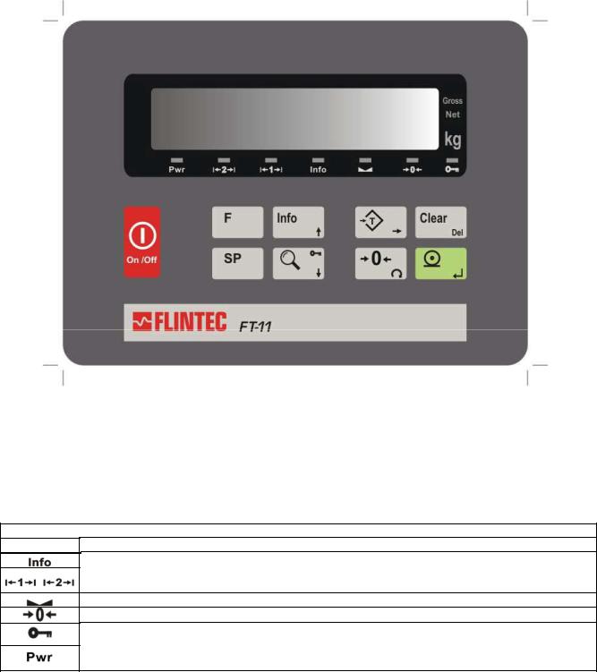
Figure 5.1 Front panel view of FT-11(D)
The weight display of FT-11(D) is a 6 digit LED with 14 mm or 20 mm height.
At the right side of the display there are three status LEDs for indicating “Gross”, “Net” and the standard unit “kg”.
Below the weight display there are several status LEDs. The meanings of these are:
Status LEDs related to the weighing process |
|
LED |
Meaning |
Info: The instrument displays information different from the weight
Range: With multi range scales these LED indicates the current operating range. For single range scales only the first range LED is lit.
Stable: The weight value on the display is stable
Center of zero: The weight is in the center of zero (see param. [203] in chap.6.4)
Key lock: is active
Power: This LED will flash in case of supply voltage decrease. If the voltage decreases too much the indicator will automatically shut off.
FT-11(D) Technical Manual, Rev. 1.35 November 2010 |
Page 12 of 52 |
5.2.Keypad
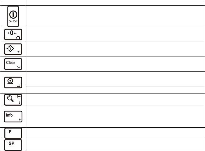
The meaning of the front panel keys and the key functions are:
Key |
Meaning |
Power On/Off: This key is used for turning the instrument on or off.
To switch off the key must be pressed and hold at least for 2 seconds.
There is no On/Off key on panel type housings.
Manual Zero: In Gross mode, if the scale doesn’t show zero while there is no load on the pan, you can zero the scale by pressing this key.
Manual Tare: Pressing this key tares the scale and gets into the Net mode.
Clear: Pressing this key clears the tare and the scale and returns to Gross mode.
Print: By pressing this key weight data and other information depending on the instrument setup are sent to a printer or a PC via serial port.
Enter: This key is used for confirming an entered value and to get to the next parameter in setup mode.
High Resolution: By pressing this key the weight value will be shown with a higher resolution for a short period.
Info: This key is being used to view Total and CN information. To toggle between these infos you have to press this key repeatedly and finally you will return to weighing mode again. To clear the total weight, you have to press the <Clear> key while the total value is seen on the display. [All C ] will appear on the display. You can confirm the deletion by pressing <Enter> or cancel by pressing the <F> key.
Function : This key is used in combination with other keys to enter any function or to quit without saving.
Setpoint: These keys are being used to view or to enter setpoint values.
5.3.Key lock
The instrument has the capability to lock the keys to avoid unauthorized person’s interference. You can activate or deactivate this function by pressing the <F> and <Key Lock> keys sequentially. The LED with the key sign (below the display) indicates the keys are locked.
For FT-11: The key(s) which would be locked are set in parameter [115].
FT-11(D) Technical Manual, Rev. 1.35 November 2010 |
Page 13 of 52 |
6.Setup and Calibration
6.1.Basics
6.1.1.Basic Setup Keys on the Frontplate
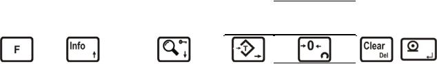
The symbols located on the lower right corner of each key indicate the function of the keys in the setup menu. The basic meanings of these keys are given in the table below.
Exit without |
Stepping forwards to |
Stepping backwards to |
Changing |
Changing the value |
Clear |
|
|
or increasing the |
Enter |
||||||
saving |
the next parameter |
the previous parameter |
the digit |
(delete) |
|||
flashing digit |
|
||||||
|
|
|
|
|
|
||
|
|
|
|
|
|
|
If you use a PC the Flintec IndFace software can be used for the setup and the calibration (for FT-11 only).
6.1.2.Entering the Setup and Calibration Menu
To enter the Setup and Calibration Menu: Press <F> and <Info> keys sequentially First [FunC ] and then [PASSWr ] prompts will be displayed sequentially.
Here you can enter the parameter block by using:
the service password: |
Press <Zero> and <Info> and <Enter> |
or the operator password: |
Press <Tare> and <Enter> |
The calibration jumper (see chapter 4.1) should be short circuit to change the legal metrological parameters in the service mode (there is black box on the top right corner of the grey coloured boxes in the calibration menu flowcharts, see Appendix 1).
The Setup and Calibration menu consists of main blocks which are displayed as [X-- ] and sub-blocks.
By using < > and < > keys you can reach previous or next main blocks. After reaching the desired main block you can get in by pressing the <Enter> key. As you enter the block you will reach the first sub-block in that main block. The sub-block address will be seen on the display as [X0- ].
You can also search between the sub-blocks by using < > and < > keys and reach the first parameter of the displayed sub-block by pressing the <Enter> key. The number of the parameter is displayed as [XY0 ]. Again
you can search between parameters by < > and < > keys.
For entering numerical values in the parameters press the <Tare> key to select the digit and press the <Zero> key to change the value.
6.1.3.Exiting the Setup and Calibration Menu
Whatever parameter block you are in – if you press the <F> key, you will get out of the active sub-block and reach the next sub-block. If you press the <F> key again you will get out of the active block and reach the next main block. If you press the <F> key once again, the [SAvE ] message appears on the display.
Here you can press
the <Enter> key to save the changes into the memory or
you can press the <Tare> key to store the changes temporarily until the power goes off oryou can press the <F> key to abort any changes.
The [Waıt] message will be displayed for a few seconds and afterwards the weighing mode will restart automatically. Especially for legal metrological usage, please don’t forget to turn the power off and remove the calibration jumper before you start the operation.
FT-11(D) Technical Manual, Rev. 1.35 November 2010 |
Page 14 of 52 |

6.2.Defining the Digital Load cells (for FT-11D only)
6.2.1.Digital Load Cell Addressing
The parameter group [22-] is used for defining and addressing the DLCs.
[22-] DLC Configuration Block
In this section the DLCs are introduced to the indicator.
[220 X] DLC Type
0 = RC3D |
This parameter must be set to “0” for type RC3D digital load cell. |
[221 XX] Quantity of DLC
Enter the quantity of DLCs used in the scale. The quantity can be selected between 1 and 16.
[222 ] DLC Addressing
The following diagram shows the addressing principles of the DLCs in a weighbridge / truck scale. The numbers in the diagram show the DLC addressing principle for easy eccentricity adjustment.
|
|
|
|
|
1 |
3 |
5 |
7 |
9 |
|
|
|
|
Entrance |
|
|
|
Exit |
|||||||
|
|
|
|
|
|
|
|
|
||||
|
|
|
|
|
|
|
|
|
|
|
|
|
|
|
|
|
|
|
|
|
|
|
|
|
|
|
|
|
|
|
2 |
4 |
6 |
8 |
10 |
|
|
|
|
|
|
|
|
|
|
|
|
||||
|
|
Figure 6.1 |
The addressing principles of the DLC’s in a weighbridge / truck scale |
|||||||||
For addressing of DLCs, press the <Tare> key. |
|
|
|
|
|
|
||||||
The messages |
[222 YY] and [ XXXXXX ] will be displayed alternately. |
|
|
|
|
|||||||
Here: |
“YY” |
DLC number /address |
|
|
|
|
|
|||||
|
|
|
“X” |
Last 6 digits of the DLC’s serial number |
|
|
|
|
||||
If you press <Enter> the next load cell will be shown, the <F> key is used to return the parameter group [20-].
You can enter the S/N, by pressing the <Tare> key. The serial numbering system of the indicator is 9 digits. First you will see the first 3 digits of the S/N. Enter this digits by pressing the <Tare> and <Zero> keys. If the serial number of the DLC is less than 9 digits, the unused digits on the left must be set to “0”. For example, if the serial number is “1234567” then “001234567” must be entered. After entering the first 3 digits, the following 6 digits are entered by pressing <Enter>.
Important hint: When addressing the connected Type RC3D load cells, the load cells should always be loaded. If the load cells are unloaded, FT-11D may show a DLC input error.
After entering all serial numbers sequentialy, the display goes to parameter group [20-]. This means all load cells are addressed and ready to work in the scale.
For replacing any load cell, you have to re-address the new load cell in parameter [222]. After installing the new load cell, turn on the indicator. Enter parameter [222] and then access the load cell address of the replaced DLC. Enter the serial number of the new load cell as described in the previous paragraph.
Note: It is always assumed that the RS485 load cell bus system is correctly terminated, please see the manual of the installed junction box.
FT-11(D) Technical Manual, Rev. 1.35 November 2010 |
Page 15 of 52 |
6.2.2.Eccentricity Adjustment
The eccentricity adjustment must be done in parameter group [32-] before the calibration of the scale. The adjustment can be done for each load cell independently or for sectional pairs. The selection is done by parameter [320]. After selection of the adjustment method , the adjustment is performed automatically as described in parameter [321].
[32-] DLC Eccentricity Adjustment Block
In this parameter group the eccentricity correction is performed automatically or manually. This adjustment must be performed automatically before calibration.
[320 X] Adjustment Method
The scale eccentricity can be adjusted in corners (each DLC individually) or in sectional pairs. 0 = Independent DLC (factory default) 1 = Sectional pair
[321 ] Auto Adjustment
After entering parameter [321] by pressing the <Tare> key, you will see [Zero CA] on the display. Unload the scale and press the <Enter> key. Do not interfere the scale during the period the [Waıt] message is displayed. Next the instrument will display [321 01]. Place a weight of at least 10% of the DLC capacity as close as possible to the independent load cell or sectional pair 1. Then press <Enter>. After some period [321 02] appears on the display. Apply the same load to the other places in sequence.
After loading all load cells / sections the message [322 ] will be shown on the display. This means the eccentricity error correction is performed automatically.
[322 ] Manual Adjustment
If needed the eccentricity error can get modified manually. You can change the error correction coefficients of the DLCs in this parameter. For entering this parameter press the <Tare> key. You can change the load cell number by the <Enter> key. For changing the coefficient of any DLC select the number of the DLC and press the <Tare> key to view and edit the coefficient. Use <Tare> and <Zero> keys for changing the value and then press the <Enter> key.
To exit this parameter press the <F> key and save the changes you applied by pressing <Enter>. The <F> key is used to quit without saving the manual corrections.
[323 X] Service mode: Set Shift Coefficients manually to 1
This parameter allows you to view the weighbridge’s performance with disabled eccentricity correction for service purposes. Using this function does not change any stored coefficient but all coefficients are “temporarily” set to value 1.
0 = Normal operation (factory default) |
1 = Service mode |
Attention: After the eccentricity adjustment a scale calibration has to be done.
FT-11(D) Technical Manual, Rev. 1.35 November 2010 |
Page 16 of 52 |
 Loading...