


Multi-Channel System
MCS-08
Technical Manual
Flintec GmbH Bemannsbruch 9 74909 Meckesheim GERMANY
www.flintec.com
MCS-08 Technical Manual, Rev. 1.04 December 2012 |
Page 1 of 52 |
Table of Contents: |
|
||
1. |
SAFETY INSTRUCTIONS........................................................................................................................... |
4 |
|
2. |
DECLARATION OF CONFORMITY ........................................................................................................... |
5 |
|
3. |
INTRODUCTION ......................................................................................................................................... |
6 |
|
3.1. |
Overview ...................................................................................................................................................... |
6 |
|
3.2. |
Specifications............................................................................................................................................... |
7 |
|
3.3. |
Housing........................................................................................................................................................ |
9 |
|
3.4. |
Accessories................................................................................................................................................ |
10 |
|
4. |
INSTALLATION......................................................................................................................................... |
11 |
|
4.1. |
Recommendations ..................................................................................................................................... |
11 |
|
4.1.1. |
Control Cabinet Design................................................................................................................................ |
11 |
|
4.1.2. |
Cabling......................................................................................................................................................... |
11 |
|
4.1.3. |
Mechanical Installation................................................................................................................................. |
11 |
|
4.2. |
Electrical Connections ............................................................................................................................... |
12 |
|
4.2.1. |
Power Supply and Grounding ...................................................................................................................... |
12 |
|
4.2.2. |
Load Cell Connection................................................................................................................................... |
12 |
|
4.2.3. |
Digital I/O Connection .................................................................................................................................. |
13 |
|
4.2.4. |
Communication Interfaces ........................................................................................................................... |
13 |
|
4.3. |
Commissioning .......................................................................................................................................... |
13 |
|
5. |
SETUP ....................................................................................................................................................... |
14 |
|
5.1. |
Installation of the xFace Software.............................................................................................................. |
14 |
|
5.2. |
Connection to the xFace Software............................................................................................................. |
14 |
|
5.3. |
N-Bus Addressing ...................................................................................................................................... |
15 |
|
5.4. |
Gateway Setup .......................................................................................................................................... |
16 |
|
5.5. |
A/D Converter Setup and Calibration ........................................................................................................ |
16 |
|
5.5.1. |
Scale Parameters ........................................................................................................................................ |
17 |
|
5.5.2. |
Scale Build and Calibration.......................................................................................................................... |
18 |
|
5.6. |
A/D Converter Performance Test .............................................................................................................. |
20 |
|
5.7. |
Digital I/O Test ........................................................................................................................................... |
21 |
|
5.8. |
N-Bus Addressing via Setup Switch .......................................................................................................... |
21 |
|
5.9. |
Back up Settings and Calibration Data ...................................................................................................... |
22 |
|
5.10. Modbus Data Structure (for MCS-08MB + MCS-08EN only)................................................................. |
23 |
||
5.11. Profibus and ProfiNet Data Structure (for MCS-08Px only) ................................................................... |
29 |
||
6. |
MCS-08AD – A/D CONVERTER MODULE.............................................................................................. |
33 |
|
6.1. |
Front View.................................................................................................................................................. |
33 |
|
6.2. |
Electrical Connections ............................................................................................................................... |
34 |
|
6.3. |
Setup and Calibration ................................................................................................................................ |
34 |
|
7. |
MCS-08DP – DISPLAY MODULE ............................................................................................................ |
35 |
|
7.1. |
Front View.................................................................................................................................................. |
35 |
|
7.2. |
Electrical Connections ............................................................................................................................... |
35 |
|
8. |
MCS-08IO – DIGITAL I/O MODULE ......................................................................................................... |
36 |
|
8.1. |
Front View.................................................................................................................................................. |
36 |
|
8.2. |
Electrical Connections ............................................................................................................................... |
36 |
|
9. |
MCS-08MB – MODBUS RTU GATEWAY ................................................................................................ |
37 |
|
9.1. |
Front View.................................................................................................................................................. |
37 |
|
9.2. |
Electrical Connections ............................................................................................................................... |
38 |
|
9.3. |
N-Bus Addressing ...................................................................................................................................... |
38 |
|
9.4. |
Modbus RTU Setup ................................................................................................................................... |
38 |
|
10. |
MCS-08PB – PROFIBUS GATEWAY ...................................................................................................... |
40 |
|
10.1. |
|
Front View .............................................................................................................................................. |
40 |
10.2. |
|
Electrical Connections............................................................................................................................ |
41 |
10.3. |
|
N-Bus Addressing .................................................................................................................................. |
42 |
10.4. |
|
Profibus Setup........................................................................................................................................ |
42 |
11. |
MCS-08PN – PROFINET GATEWAY ....................................................................................................... |
43 |
|
11.1. |
|
Front View .............................................................................................................................................. |
43 |
11.2. |
|
Electrical Connections............................................................................................................................ |
44 |
11.3. |
|
N-Bus Addressing .................................................................................................................................. |
45 |
11.4. |
|
ProfiNet Setup ........................................................................................................................................ |
45 |
MCS-08 Technical Manual, Rev. 1.04 December 2012 |
Page 2 of 52 |

12. |
MCS-08EN – ETHERNET GATEWAY...................................................................................................... |
46 |
12.1. |
Front View .............................................................................................................................................. |
46 |
12.2. |
Electrical Connections............................................................................................................................ |
47 |
12.3. |
N-Bus Addressing .................................................................................................................................. |
48 |
12.4. |
Ethernet Setup ....................................................................................................................................... |
48 |
13. |
ERROR TABLE ......................................................................................................................................... |
49 |
14. |
DIAGNOSTICS .......................................................................................................................................... |
50 |
15. |
FREQUENTLY ASKED QUESTIONS ...................................................................................................... |
51 |
RIGHTS AND LIABILITIES
All rights reserved.
No part of this publication may be reproduced, stored in a retrieval system, or transmitted in any form or by any means, mechanical, photocopying, recording, or otherwise, without the prior written permission of Flintec GmbH
No patent liability is assumed with respect to the use of the information contained herein. While every precaution has been taken in the preparation of this book, FLINTEC assumes no responsibility for errors or omissions. Neither is any liability assumed for damages resulting from the use of the information contained herein.
The information herein is believed to be both accurate and reliable. FLINTEC, however, would be obliged to be informed if any errors occur. FLINTEC cannot accept any liability for direct or indirect damages resulting from the use of this manual.
FLINTEC reserves the right to revise this manual and alter its content without notification at any time.
Neither FLINTEC nor its affiliates shall be liable to the purchaser of this product or third parties for damages, losses, costs, or expenses incurred by purchaser or third parties as a result of: accident, misuse, or abuse of this product or unauthorized modifications, repairs, or alterations to this product, or failure to strictly comply with FLINTEC operating and maintenance instructions.
FLINTEC shall not be liable against any damages or problems arising from the use of any options or any consumable products other than those designated as Original FLINTEC Products.
NOTICE: The contents of this manual are subject to change without notice.
Copyright © 2010 – 2012 by Flintec GmbH, 74909 Meckesheim, Bemannsbruch 9, Germany
MCS-08 Technical Manual, Rev. 1.04 December 2012 |
Page 3 of 52 |

1. SAFETY INSTRUCTIONS
CAUTION READ this manual BEFORE operating or servicing this equipment. FOLLOW these instructions carefully. SAVE this manual for future reference. DO NOT allow untrained personnel to operate, clean, inspect, maintain, service, or tamper with this equipment. ALWAYS DISCONNECT this equipment from the power source before cleaning or performing maintenance. CALL FLINTEC ENGINEERING for parts, information, and service.
WARNING ONLY PERMIT QUALIFIED PERSONNEL TO SERVICE THIS EQUIPMENT. EXERCISE CARE WHEN MAKING CHECKS, TESTS AND ADJUSTMENTS THAT MUST BE MADE WITH POWER ON. FAILING TO OBSERVE THESE PRECAUTIONS CAN RESULT IN BODILY HARM.
WARNING FOR CONTINUED PROTECTION AGAINST SHOCK HAZARD CONNECT TO PROPERLY GROUNDED OUTLET ONLY. DO NOT REMOVE THE GROUND PRONG.
WARNING DISCONNECT ALL POWER TO THIS UNIT BEFORE REMOVING THE FUSE OR SERVICING.
WARNING BEFORE CONNECTING/DISCONNECTING ANY INTERNAL ELECTRONIC COMPONENTS OR INTERCONNECTING WIRING BETWEEN ELECTRONIC EQUIPMENT ALWAYS REMOVE POWER AND WAIT AT LEAST THIRTY (30) SECONDS BEFORE ANY CONNECTIONS OR DISCONNECTIONS ARE MADE. FAILURE TO OBSERVE THESE PRECAUTIONS COULD RESULT IN DAMAGE TO OR DESTRUCTION OF THE EQUIPMENT OR BODILY HARM.
CAUTION OBSERVE PRECAUTIONS FOR HANDLING ELECTROSTATIC SENSITIVE DEVICES.
MCS-08 Technical Manual, Rev. 1.04 December 2012 |
Page 4 of 52 |

2. DECLARATION OF CONFORMITY
EG-Konformitätserklärung
EC-Declaration of Conformity
Monat/Jahr: month/year: |
06/2010 |
Hersteller: Manufacturer: |
Flintec GmbH |
Anschrift: Address: |
Bemannsbruch 9 |
|
D-74909 Meckesheim |
|
Deutschland / Germany |
Produktbezeichnung: Product name: |
MCS-08 Multi Channel System |
Das bezeichnete Produkt stimmt mit folgenden Vorschriften der Europäischen Richtlinien überein:
This product confirms with the following regulations of the Directives of the European Community
Richtlinie 2004/108/EG des Europäischen Parlaments und des Rates vom 15. Dezember 2004 zur Angleichung der Rechtsvorschriften der Mitgliedstaaten über die elektromagnetische Verträglichkeit und zur Aufhebung der Richtlinie 89/336/EWG
Richtlinie 2006/95/EG Niederspannungs-Richtlinie
Directive 2004/108/EC of the European Parliament and of the Council of 15th December 2004 on the approximation of the laws of the Member States relating to electromagnetic compatibility and repealing Directive 89/336/EEC
Directive 2006/95/EC Low Voltage Directive
Die Absicherung aller produktspezifischen Qualitätsmerkmale erfolgt auf Basis eines zertifizierten Qualitätsmanagement-Systems nach DIN ISO 9001.
Diese Erklärung bescheinigt die Übereinstimmung mit den genannten Richtlinien, beinhaltet jedoch keine Zusicherung von Eigenschaften.
All product-related features are assured by a quality system in accordance with ISO 9001.
This declaration certifies the conformity with the listed directives, but it is no promise of characteristics.
Folgende Normen werden zum Nachweis der Übereinstimmung mit den Richtlinien eingehalten:
As a proof of conformity with the directives following standards are fulfilled:
EN 61326-1
EN 60950-1
Elektrische Mess-, Steuer-, Regelund Laborgeräte - EMV-Anforderungen - Teil 1: Allgemeine Anforderungen (IEC 61326-1:2005)
Electrical equipment for measurement, control and laboratory use - EMC requirements - Part 1: General requirements (IEC 61326-1:2005)
Einrichtungen der Informationstechnik - Sicherheit - Teil 1: Allgemeine Anforderungen (IEC 60950- 1:2005, modifiziert);
Information technology equipment - Safety - Part 1: General requirements (IEC 60950-1:2005 modified)
MCS-08 Technical Manual, Rev. 1.04 December 2012 |
Page 5 of 52 |

3. INTRODUCTION
3.1. Overview
Type MCS-08 is a powerful and economic state-of-the-art multi channel system for static and dynamic weighing applications plus force and torque measurements.
The basic measurement module is the 1-channel type MCS-08AD A/D converter which converts the analogue low level signal from a load cell or a strain gauge sensor to a digital high-resolution and high-accuracy signal. All standard weighing functions are available on this A/D converter.
For bus connections, gateways such as Profibus DP, ProfiNet, Modbus RTU and Ethernet TCP/IP are available. The gateway can communicate via the internal system bus (named N-bus) with up to 8 type MCS08AD A/D converters.
For local display purposes the internal system bus can be extended with one optional type MCS-08DP Display module. The system can be extended with optional control signals located on the type MCS-08IO Digital I/O module. The gateway can communicate via the internal system bus with up to eight type MCS-08IO modules.
The type MCS-08 Multi-Channel System comprises various hardware modules which are
MCS-08AD |
MCS-08MB |
MCS-08PB |
MCS-08PN |
A/D Converter |
Modbus RTU Gateway |
Profibus DP Gateway |
ProfiNet Gateway |
MCS-08IO |
MCS-08DP |
MCS-08EN |
Digital I/O Module |
Display Module |
Ethernet Gateway |
Figure 3.1 – MCS-08 hardware modules
MCS-08 Technical Manual, Rev. 1.04 December 2012 |
Page 6 of 52 |

E xte rn a l b u s
N -b u s |
N -b |
u s |
|
|
|
Figure 3.2 – MCS-08 bus system
A basic configuration of type MCS-08 Mult Channel System is shown in Figure 3.2. In this configuration the gateway module is the master of the internal N-bus and it simultaneously acts as a slave for the external bus. The gateway connects the external network with the locally installed MCS-08 hardware modules and transmits commands and responses to and from the external bus. It scans all hardware modules for their status and then transmits this status information continuously to the external bus controller.
3.2. Specifications
1-channel A/D Converter: Type MCS-08AD
 A/D Converter
|
Type |
24-bit Delta-Sigma ratiometric with integral analogue and digital filter |
|
Analogue input range |
0 mV to 18 mV (unipolar) or -18 mV to +18 mV (bipolar), switchable |
|
Linearity |
< 0.0015 % FS |
|
Temperature coefficient |
< 2 ppm/°C |
|
Min. input sensitivity |
0.1 µV/d |
|
Conversion rate |
Up to 800 measurement values per second |
|
Internal resolution |
Up to 8 million counts |
|
External resolution |
Up to 100000 counts (weight value, force, torque) respective |
|
1 million raw counts (unipolar) respective 2 million raw counts (bipolar) |
|
|
|
|
|
Calibration and Weighing Functions: |
|
|
|
|
|
Calibration |
Electronic calibration without test weights (eCal) or calibration by test weights |
|
Digital filter |
10 step adjustable digital adaptive filter |
|
Weighing functions |
Tare, zero, auto zero tracking, motion detection, auto-zero at power-up, save |
|
tare at power-off, increased resolution |
|
|
|
|
|
|
|
|
Load cells: |
|
|
Excitation: |
5 V DC at 58...1200 Ω, max. 100 mA |
|
Number of load cells: |
Up to 6 load cells à 350 Ω or 18 load cells à 1100 Ω in parallel |
|
Connection: |
4- or 6-wire technique, cable length 250 m/mm² for 6-wire connection |
|
Communication and Setup: |
|
|
|
|
|
Setup & calibration |
By PC software via gateway module, backup data stored on PC |
|
Response time |
< 4 ms (delay after each read or write command) |
|
Power supply: |
|
|
DC power supply |
10 to 28 VDC, < 200 mA, not galvanically isolated |
|
Environment and Enclosure: |
|
|
Operating temperature |
Between -10 °C and +40 °C at maximum 85% RH, non-condensing |
|
Enclosure & protection class |
Polyamide, for DIN-rail mounting, protection class IP20 |
|
Dimensions & weight |
99 x 22.5 x 114.5 mm (L x W x H), weighs approx. 100 g |
MCS-08 Technical Manual, Rev. 1.04 December 2012 |
Page 7 of 52 |

Gateway Modules
 General
|
Internal bus system |
Communication with up to |
|
|
8x type MCS-08AD and up to 8x type MCS-08IO and 1x type MCS-08DP |
||
|
|
||
|
|
|
|
|
Serial interface RS232C |
9600 baud (8, N, 1), used as service interface, communication to each |
|
|
connected type MCS-08AD respective |
||
|
|
||
|
|
|
|
|
Response time |
< 4 ms (delay after each read or write command) |
|
|
Power supply: |
|
|
|
|
|
|
|
DC power supply |
10 to 28 VDC, < 100 mA, not galvanically isolated |
|
|
Environment and Enclosure: |
|
|
|
Operating temperature |
Between -10 °C and +40 °C at maximum 85% RH, non-condensing |
|
|
Enclosure & protection class |
Polyamide, for DIN-rail mounting, protection class IP20 |
|
|
Dimensions & weight |
99 x 45 x 114.5 mm (L x W x H), weighs appr. 150 g |
|
|
|
|
|
|
Profibus DP Gateway Module: Type MCS-08PB |
||
|
|
|
|
|
Communication: |
|
|
|
Profibus DP-V0 + DP-V1 |
9.6 kbit/s to 12 Mbit/s (automatic), galvanically isolated interface |
|
|
Address range |
1...126 |
|
|
|
|
|
|
ProfiNet Gateway Module: Type MCS-08PN |
|
|
|
|
|
|
|
Communication: |
|
|
|
|
|
|
|
ProfiNet |
100 Mbit/s (full duplex), galvanically isolated interface |
|
|
IP settings |
DHCP or manual setup by PC software |
|
|
|
|
|
|
|
|
|
|
Modbus RTU Gateway Module: Type MCS-08MB |
|
|
|
|
|
|
|
Communication: |
|
|
|
|
|
|
|
Serial interface RS485A |
Serial interfac RS485, 1200 to 57600 baud (8N1, 7E1, 7O1), |
|
|
|
bus capability up to 31 units |
|
|
|
|
|
|
Address range |
1...31 |
|
|
|
|
|
|
Ethernet TCP/IP Gateway Module: Type MCS-08EN |
|
|
|
|
|
|
|
Communication: |
|
|
|
|
|
|
|
Ethernet TCP/IP |
10 Mbit/s (full duplex), galvanically isolated interface |
|
|
IP settings |
Manual setup by PC software |
|
|
Other |
Web client interface |
|
|
|
|
|
|
Digital I/O Module: Type MCS-08IO |
||
|
|
|
|
|
Digital I/O: |
|
|
|
Inputs |
4 opto-isolated inputs (12...30 V DC) |
|
|
|
|
|
|
Outputs |
4 potential-free NO relays, 1A @ 250 V AC, 30 V DC |
|
|
Input function |
Control input to communication interface |
|
|
Output function |
Control output from communication interface |
|
|
Communication and Setup: |
|
|
|
|
|
|
|
Setup & calibration |
By PC software via gateway module, backup data stored on PC |
|
|
Response time |
< 4 ms (delay after each read or write command) |
|
|
Power supply: |
|
|
|
|
|
|
|
DC power supply |
10 to 28 VDC, < 100 mA, not galvanically isolated |
|
|
Environment and Enclosure: |
|
|
|
|
|
|
|
Operating temperature |
Between -10 °C and +40 °C at maximum 85% RH, non-condensing |
|
|
Enclosure & protection class |
Polyamide, for DIN-rail mounting, protection class IP20 |
|
|
Dimensions & weight |
99 x 22.5 x 114.5 mm (L x W x H), weighs appr. 100 g |
|
MCS-08 Technical Manual, Rev. 1.04 December 2012 |
Page 8 of 52 |

Display Module: Type MCS-08DP
 Local Display:
Display |
LED red, 10.2 mm high, 5 digits, with overflow indication |
Status LEDs |
Selected channel; net, no motion, zero and power-on state of the selected |
|
channel |
|
|
Keyboard |
2-key membrane with tactile feedback |
Refresh time |
250 ms |
Power supply: |
|
|
|
DC power supply |
10 to 28 VDC, < 100 mA, not galvanically isolated |
Environment and Enclosure: |
|
|
|
Operating temperature |
Between -10 °C and +40 °C at maximum 85% RH, non-condensing |
Enclosure & protection class |
Polyamide, for DIN-rail mounting, protection class IP20 |
Dimensions & weight |
99 x 45 x 114.5 mm (L x W x H), weighs appr. 140 g |
3.3. Housing
MCS-08 modules come within a polyamide housing sealed to IP20. They are prepared for mounting on NS 37/7 or NS 35/15 standard DIN rails (see drawings).
22,5 mm |
45 mm |
99 mm |
114,5 mm
View A |
View B |
Side view |
View A: MCS-08AD, MCS-08IO
View B: MCS-08PB, MCS-08PN, MCS-08MB, MCS-08EN
Figure 3.3 – Dimensions
MCS-08 Technical Manual, Rev. 1.04 December 2012 |
Page 9 of 52 |

3.4. Accessories
Accessories supplied with the modules
The following accessories are supplied together with the modules. |
08AD-MCS |
08IO-MCS |
08DP-MCS |
08PB-MCS |
08PN-MCS |
08MB-MCS |
08EN-MCS |
|
If any part is missing, please contact your supplier. |
||||||||
|
|
|
|
|
|
|
||
|
|
|
|
|
|
|
|
|
4-pin and 5 mm pitch plug, light gray, power connector |
1 |
1 |
1 |
1 |
1 |
1 |
1 |
|
5-pin and 3.81 mm pitch plug, light gray, N-bus connector |
1 |
1 |
2 |
2 |
2 |
2 |
2 |
|
3-pin and 3.81 mm pitch plug, green, RS232C or RS485 |
|
|
|
1 |
1 |
2 |
1 |
|
7-pin and 3.81 mm pitch plug, black, for load cell cable |
1 |
|
|
|
|
|
|
|
5-pin and 3.81 mm pitch plug, green, for digital inputs |
|
1 |
|
|
|
|
|
|
8-pin and 3.81 mm pitch plug, green, for digital outputs |
|
1 |
|
|
|
|
|
|
Installation CD (xFace software, technical documentation) |
|
|
|
1 |
1 |
1 |
1 |
Table 3.1 – Accessories supplied with instrument
Accessories sold separately
The following accessories are available from Flintec.
MCS-08AD |
MCS-08IO |
MCS-08DP |
MCS-08PB |
MCS-08PN |
MCS-08MB |
MCS-08EN |
RS-232C cable (3 m long) for connection with PC |
|
|
1 |
1 |
1 |
1 |
Junction box for load cell connection |
Refer to Flintec catalog |
|
||||
Open end load cell cable, 6 wire ( 0.22 cm2 each ) |
Max. 200 meter length |
|
||||
Table 3.2 – Accessories supplied separately
MCS-08 Technical Manual, Rev. 1.04 December 2012 |
Page 10 of 52 |
4. INSTALLATION
PRECAUTION: Please read this manual carefully before you install the instrument. If you apply all recommendations in this chapter you will increase the reliability and long term performance of your system.
4.1. Recommendations
4.1.1. Control Cabinet Design
Warning: Please follow the following warnings for designing the control cabinet which will increase the reliability of your system.
The control cabinet should be designed therefor the MCS-08AD modules can operate safely. The panel should be placed in a clean area, without getting direct sun light if possible, with a temperature between -10 ºC and +40 ºC, humidity not exceeding 85% non-condensing. All external cables should be installed safely to avoid mechanical damages.
MCS-08 modules are very low level signal measuring instruments. To avoid electrical noise, the instruments should be separated from equipment that produces electrical noise. Preferably use a metal cabinet against radio frequency interference, to protect against electromagnetic disturbance the cabinet shall be connected to ground. Keep the load cell cable trays separated from others, if possible. If there is noise-generating equipment such as heavy load switches, motor control equipment, inductive loads etc., please be careful against the EMC interference in the cabinet. If possible protect MCS-08 modules by a Faraday cage or install them in a separate section or install them far a way from this kind of equipment. Install parallel reverse diodes to the DC inductive loads like relays, solenoids etc. to minimize voltage peaks on the DC power lines.
4.1.2. Cabling
All cables coming to the control cabinet shall be shielded. Please use separate cable trays for these low signal level cables. Distance from load cell cables, interface cables and DC power supply cables to power line cables shall be 50 cm at minimum.
4.1.3. Mechanical Installation
After designing the control panel and installing DIN rails according to the recommendation in this chapter, install the N-bus connectors on the DIN rail as shown in figure 4.1.
Figure 4.1 – N-bus connectors installed on DIN-rail
Place the modules on the DIN rail for making the connection between the N-bus and the MCS-08 modules as shown on figure 4.2. Be sure that the mechanical installation and the N-Bus connection of the modules are done properly.
Figure 4.2 – Installation on DIN-rail
MCS-08 Technical Manual, Rev. 1.04 December 2012 |
Page 11 of 52 |

4.2. Electrical Connections
Warning: Please always remember that MCS-08AD modules are very low voltage measuring instruments. Your control cabinet design and proper installation increases the reliability and the performance of the instrument. Please do not forget that the instrument must be powered off before inserting or removing any peripheral connector. All required electrical connections should be done as described below.
4.2.1. Power Supply and Grounding
The power supply voltage of the instrument shall be between 12 V DC and 28 V DC. The current consumption of the power supply will be calculated by multiplying 0.2 A and the quantity of instruments. The pin configuration of the 24 V DC power supply connector located at the bottom front of the instrument is shown below in figure 4.3.
MCS-08AD MCS-08IO (front view)
24V 0V |
24V 0V |
Warning: Do not forget to connect the Shield pin to the reference ground.
Figure 4.3 – The pin layout of 24 V DC connector
MCS-08DP,
MCS-08PB,
MCS-08PN, MCS-08MB and MCS-08EN (front view)
The quality of the instrument‟s ground will determine the accuracy and the safety of your measuring system. A proper ground connection is needed to minimize extraneous electrical noise effects on the measurement. A poor ground can result in an unsafe and unstable operation. It is important that the instrument should not share power lines with noise-generating equipment such as heavy load switching, motor control equipments, inductive loads, etc. If the condition of the power line in the plant is poor, prepare a special power line and grounding. Before interfering the instrument, turn off the power and wait at least for 30 seconds.
4.2.2. Load Cell Connection
To avoid damages, the load cell wiring should be made carefully before energizing the instrument. Load cell connection details are shown below in figure 4.4. In 4-wire installations the sense and excitation pins with the same polarity should be short circuited at the connector side. If you have a junction box in your system, use a 6 wire cable between the MCS-08AD moduler and the junction box, and short circuit these pins at junction box for better performance.
4 wire LC connection |
6 wire LC connection |
Load Cell
Connector
Warning: Connect the load cell cable shield to the reference ground or the shield pin of the load cell connector.
Figure 4.4 – Load cell connection
MCS-08 Technical Manual, Rev. 1.04 December 2012 |
Page 12 of 52 |

4.2.3. Digital I/O Connection
MCS-08IO modules have the digital I/O connectors on the module‟s front. The I/O connection diagram is shown in figure 4.5. The outputs are potential-free contacts (1A @ 250 VAC, 30 V DC) and the inputs are opto-isolated
(12…30 V DC).
M C S -08IO m odule
Figure 4.5 – Digital I/O connection
4.2.4. Communication Interfaces
Please refer to the corresponding chapter: |
|
MCS-08MB (Modbus RTU) |
see chapter 9.2 |
MCS-08PB (Profibus) |
see chapter 10.2 |
MCS-08PN (ProfiNet) |
see chapter 11.2 |
MCS-08EN (Ethernet and Modbus TCP) |
see chapter 12.2 |
4.3. Commissioning
PRECAUTION: Please read this manual carefully before energizing the instrument. Perform the commissioning operation according the procedure given in this chapter. Only trained persons are allowed for cleaning, commissioning, checking and servicing of the instrument. The interference of untrained person may cause some unwanted damages or injuries.
Before energizing the instrument, please make the required mechanical and electrical installations. After power on, you have to setup your MCS-08 system before you can start to use the bus interface.
Install the xFace software onto your PC as described in chapter 5 Setup. The xFace software is used for setup, calibration and testing of MCS-08 systems.
After you have successfully checked the performance of the instrument with xFace, you can begin to use the system in your application.
MCS-08 Technical Manual, Rev. 1.04 December 2012 |
Page 13 of 52 |

5. SETUP
PRECAUTION: Please read this manual carefully before energizing the system. Perform the commissioning according the procedure given in chapter 4.3. Only trained person are allowed for commissioning, checking, cleaning and servicing of the instrument. The interference of untrained person may cause some unwanted damages or injures.
MCS-08 systems are setup and calibrated by the xFace software supplied with the instrument.
The instruments shall be setup in the sequence described below before you can use the bus interface. Install the xFace software onto your PC
Connect your PC with the gateway over the serial interface (RS232 respective RS485) Set up the N-bus addresses and the gateway module
Set up and calibrate the A/D Converters Check the performance of the A/D Converters Check the performance of the Digital I/Os
5.1. Installation of the xFace Software
Please follow following steps to install the xFace software: Close all applications on your PC
Insert the CD that contains the xFace software into the CD-ROM drive
Double click “Setup.exe” to start the installation. The setup Wizard is displayed.
Follow the menus in the setup wizard step by step.
After finishing the installation, the Setup Wizard will inform you about the success of the software installation. Click the OK button.
After closing the Setup Wizard you can start to use the xFace software.
Typ FAD-30
Typ FAD-40
Typ MCS-08 Select one of the MCS-08 gateways and press OK button.
Figure 5.1 – xFace Type Selector Window
5.2. Connection to the xFace Software
The connection between the MCS-08 gateway module and the xFace software is done via the RS232C service port for all gateway modules. Alternatively Ethernet (for MCS-08EN only) or RS-485 (for MCS-08MB only) can be used for this connection. You can purchase a suitable PC connection cable as an accessory from Flintec (Refer to chapter 3.4.2).
After running the xFace software select the gateway model you use (see figure 5.1.). Select the PC‟s communication port within the Connection settings menu in the tools tab (see figure 5.2) and click the connect icon. After the communication between the MCS-08 gateway module and your PC has successfully started the traffic light of the connect icon turns from red to green.
Protocol: Select the setup port of the instrument. MCS-08MB modules can be setup over RS485 or RS232C. Other models can be setup over RS232C.
Com Port: Select the communication port of the PC Address: Select the RS-485 address, if RS-485 is selected Baud rate: Select the RS-485 baud rate, if RS-485 is selected
Setting: Select the RS-485 communication port setting, if RS-485 is selected
Figure 5.2 – xFace Connection Settings
MCS-08 Technical Manual, Rev. 1.04 December 2012 |
Page 14 of 52 |
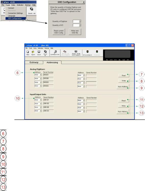
5.3. N-Bus Addressing
First define the number of MCS-08AD modules and MCS-08IO modules in the GSD configuration.
Figure 5.3 – xFace GSD configuration
Figure 5.4 – xFace N-bus Addressing Tab
Address: Addresses of the MCS-08AD modules
Read button: Reads the N-address and the serial number of the MCS-08AD module
Write button: Writes the N-address to the MCS-08AD module with the corresponding serial number
Auto Address: Fills the address fields with values 0 to 7
Address: Addresses of the MCS-08IO modules
Read button: Reads the N-address and the serial number of the MCS-08IO module
Write button: Writes the N-address to the MCS-08IO module with the corresponding serial number
Auto Address: Fills the address fields with values 0 to 7
For the first time connection to a MCS-08 system only the gateway and the addressing tabs become active. First address the modules to the N-Bus to activate the modules within the MCS-08 system.
Addressing MCS-08AD modules to the N-Bus: First click the „Read‟ button to read the serial numbers and the addresses. Then define an address for each MCS-08AD module within the system. Then click the „Write‟ button to save the address settings. If the addressing of the MCS-08AD modules to the N-Bus is successfully completed, then the Setup, the Calibration and the Converter Status tabs as well as the Scale Address and the Visual Weight Display will be activated.
Addressing Input/Output Instruments to N-Bus: First, click the „Read‟ button to read serial numbers and the addresses. Then define an address for each MCS-08IO module within the system. Then click the „Write‟ button to save the address settings. If the addressing of the MCS-08IO modules to the N-Bus is successfully completed, then the I/O Status tab will be activated.
MCS-08 Technical Manual, Rev. 1.04 December 2012 |
Page 15 of 52 |

5.4. Gateway Setup
Depending on their interface structure gateways have an interface parameter which has to be set up BEFORE the external communication bus can be started. The gateway setup is done in the gateway tab. Details on the gateway parameters and their descriptions can be found in the corresponding gateway chapter.
Figure 5.5 – xFace Gateway Tab
Gateway Information: Indicates the bus type, the firmware and hardware version numbers and the serial number of the gateway module
Active A/D Converter: Indicates the active MCS-08AD module and the N-Bus address within the system. For more information refer to chapter 6
Active Digital I/O: Indicates the active MCS-08IO module and the N-Bus address within the system. For more information refer to chapter 8
External Bus Setup: This block allows the user to set up the external bus parameters. Each gateway type has its own parameter set corresponding to the bus type.
5.5. A/D Converter Setup and Calibration
PROPOSAL: Read the chapter about MCS-08AD modules carefully before you set up and calibrate a module. This will increase the performance of your weighing system by applying a proper setup and calibration.
When you set up a MCS-08AD module, if there is any within the system, then first select the scale number by pressing the scale selection button.
Figure 5.6 – xFace A/D Converter Setup
MCS-08 Technical Manual, Rev. 1.04 December 2012 |
Page 16 of 52 |
 Loading...