

Page 1
FLINTEC ...the right weigh
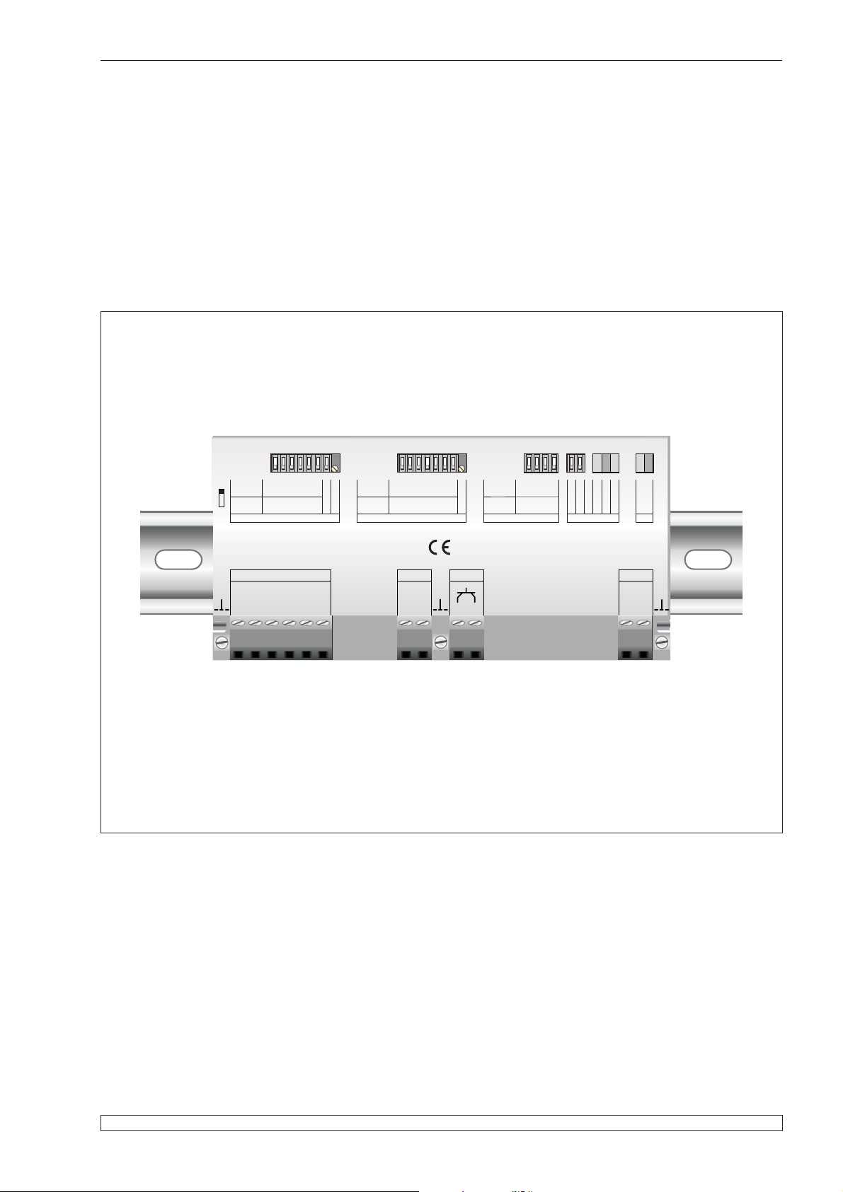
Analogue Amplifier Type LAC 74.1
MANUAL
Off
On
0
IN
mV
0,5
2,0
1,0
0
%at
2mV/V
SET ZERO Pot ccw = calib.
2,5
5
10
FLINTEC
LOAD CELLS 10Vdc 120mA
Exc
Inp Inp Sen
Sen
+++
_
4,0
8,0
16,0
40
20
80
Exc
__
Relative
gain
*
Resolu.
1000 n
Pol. +/-
Fine adj.
*
SET SPAN Pot ccw = calib.
1,0
0,25
60
50
Out
20mA/
10V
Gnd
0,5
40
1,0
30
2,0
20
4,0
13
8,0
7
16,0
4
Fine adj.
f
t
CUT
ms
SET
10
3,3
5
16
50
FILTER
160
0,33
500
0-20/4-20
20mA/10V
OUTPUT
In range.
Under
Over
CND
Error
Pwr. OK
1
33
LAC 74.1
Log Err.
U
Gnd
I/V
C
PWR
12-24Vdc
GND
+
Document No G133 Rev2 UK
www.flintec.com
Manual LAC 74.1 Page 1
Page 2
...the right weigh FLINTEC
LAC 74.1 Specifications
Linearity < 0.01 %
Analogue input range
Excitation 10 V DC, for up to 4 load cells 350 Ohm, 6 wire technique
Safety circuit
Zero adjustment (Offset) ±3 mV/V, zero adjustment by DIP switches and fine trimming potentiometer
Current output
Voltage output
Input filters 0.33 ... 33 Hz, DIP switch selectable (5 steps)
Temperature range –20 °C to +50 °C (operating); –20 °C to +60 °C (storage)
Temperature effects
Enclosure
Power supply
All dimensions in mm. Dimensions and specifications are subject to change without notice.
±0.1 mV/V to 3.5 mV/V, gain adjustment by DIP-switches and fine trimming
potentiometer
Logic output, Open Collector, normally closed, opens in case of error (max. 30 V
DC, 300 mA):
- Load cell input- or sense wires signals are out of range
- The current or voltage output is out of range
-Powerfail
0 ... 20 mA or 4 ... 20 mA; R
0 ... 10 V; R
Load
³ 500 Ohm
Load
³ 500 Ohm
on zero 25 ppm/°K
on span 50 ppm/°K
135 x 66 x 18 mm, protection IP40, for standard 35 mm DIN-rail mounting,
(special housing on request)
12 ... 24 V DC ±10% or 12 ... 18 V AC, 3 W max., reversed polarity and excess
voltage protected
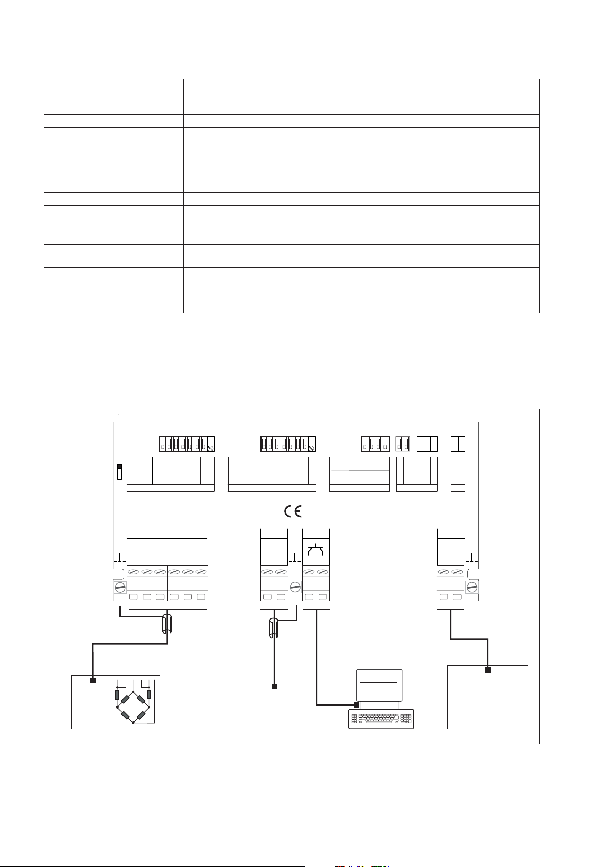
System Configuration
mV
0
0,5
0
2,5
Off
IN
%at
2mV/V
On
SET ZERO Pot ccw = calib.
FLINTEC
LOAD CELLS 10Vdc 120mA
Exc
Inp Inp Sen
Sen
+++
Load cells
connection
;
6-wire
1,0
5
_
4,0
2,0
10
20
__
8,0
40
16,0
80
Exc
Relative
gain
*
Resolu.
1000 n
Pol. +/-
Fine adj.
*
SET SPAN Pot ccw = calib.
PLC and/or
computer with
analogue input
1,0
0,25
60
50
Out
20mA/
10V
Gnd
PLC
system
0,5
40
1
33
ms
10
3,3
5
50
16
FILTER
160
0,33
500
0-20/4-20
20mA/10V
OUTPUT
In range.
Under
Over
Error
CND
Pwr. OK
1,0
30
2,0
20
4,0
13
8,0
7
16,0
4
Fine adj.
f
t
CUT
SET
LAC 74.1
Log Err.
U
Gnd
I/V
C
Open Collector output,
normally closed,
opens in case of
LAC 74.1 error
Silo Nr.: 1
Netto : 17285 kg
Tara : 1458 kg
PWR
12-24Vdc
GND
+
-----------------------
Power supply
12...24 V DC
14...28 V AC
Page 2 Manual LAC 74.1
Page 3
FLINTEC ...the right weigh
Calibration of the analogue output
1. Mounting the module
The SG module has to be installed in a cabinet in compliance with (inter)national electrical
regulations. Connection details are printed on the upper face of the amplifier housing.
The amplifier module supports 6 wire technique. If you are using a 4 wire load cell, the
“Exc +” and “Sen +” terminals must be shorted together as well as the “Exc –“ and “Sen –“
terminals.
2. Adjustment settings
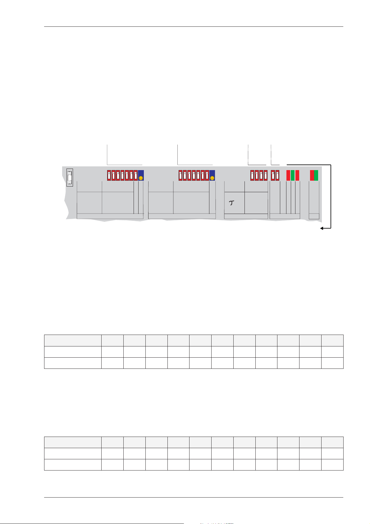
All DIP-switches and potentiometers are positioned near the top edge of the housing.
DIP-switches and
potentiometer
for zero setting
OFF
ON
mV
0
0,5
1,0
2,0
0
5
10
2,5
IN
%at
2mV/V
SET ZERO Pot ccw =calib.
DIP-switches and
4,0
8,0
16,0
Pol. +/-
20
40
80
Fine adjust
potentiometer
for gain setting
Relative
gain*
Resolution
*1000n
SET SPAN Pot ccw =calib.
0,1
60
0,25
50
DIP-switches
for low pass filter
0.5-33 Hz
0,5
1,0
2,0
4,0
8,0
16,0
7
40
4
30
20
13
signal out of range (e.g. negative too)
signal out of range (e.g. > 2 mV/V)
fCUT
Fine adjust
ms
SET FILTER
error message safety logic
DIP-switches for choosing
analogue output
0-20 mA or 4-20 mA or 0-10 V.
1
33
10
3,3
0,33
5
16
50
160
500
input signal OK
power is ON
20mA o.10V
0-20 o. 4-20mA
OUTPUT
Over
Under
In range
=
=
In range
=
=
=
Power OK
Error
Power OK
CND
Under
Over
Error
3. Setup DIP-switches
Zero setting:
The left six DIP-switches permit the off-set to be adjusted in steps of 0.5 mV throughout the
range of 0 to 31.5 mV. The seventh DIP-switch sets the polarity of the zero adjustment, either
Positive (ON) to make the output more positive or Negative (OFF) to make the output more
negative. The 20-turn potentiometer permits fine trimming of the zero point.
The total range is + or – 80%.
DIP-switch ON none 123456allPol.Pot.
Relative to 20 mV % 0 2.5 5 10 20 40 80 157.5 +/– 3
InputatZeroV
out
mV00.512481631.5+/–0.6
Span (Gain) setting:
The seven DIP-switches permit the relative gain to be set in 128 steps of 0.25x over the range
1 to 32. The 20-turn potentiometer permits fine trimming. Therefore, any input signal range
between 0.1 mV/V and 3.2 mV/V can be used to generate the full scale output (0 – 10 V or
0 – 20 mA or 4 – 20 mA). Note that the higher the gain, the lower the resolution that can be
obtained.
DIP-switch ON none 1234567allPot.
Relativegainfactorf10.250.5124816330.3
Inputat10VV
out
Manual LAC 74.1 Page 3
mV32302824168421xx
Page 4

...the right weigh
FLINTEC
Current output: The I
range can be set to0–20mAor4–20mA.
out
Voltage output: 0 – 10 V output only if current output 0 – 20 mA is selected.
Low-pass filter:
By combining the four DIP-switches the low-pass filter can be set from 0.33 Hz up to 33 Hz.
Factory default is 33 Hz.
DIP-switch ON none 1234
Time constant ms 5 16 50 160 500
Settling time ms 40 130 400 1300 4000
Cut off frequency Hz 33 10 3.3 1 0.33
4. Output current (or voltage) adjustment
Use a digital multimeter with at least a 5 digit display. Connect to current or voltage output as
appropriate.
Remark: The multimeter should have a current resolution of 0.01 mA to get a calibration
accuracy of 0.05%.
5. Setting Zero
With no load on the weighing system, use the Zero DIP-switches to initially set the zero value
coarsely to approximately 4 mA (or whatever value you want at no load). Then use the fine
zero potentiometer to make the final adjustment.
6. Setting the Span (Gain)
If you know that you will need to change the gain substantially, it is best to adjust the span
DIP-switches first and then reset the zero prior to applying any loads. For instance if you are
only using 40% (8 mV) ofthe load cell range (20 mV) you will needto increase the relative gain
to 4x (DIP switch 5 on). See Gain table overleaf. Apply the calibration load and use the fine
potentiometer to give the required result.
Stages 5 and 6 may have to repeated to achieve the required results.
7. Weighing system ready for use
The weighing system is now calibrated and ready for use.
8. Safety
If a short circuit occurs on the load cell supply wires, output wires or sense wires, the output
from the LAC 74.1 will fall to zero as a fail safe condition. With the 4 – 20 mA range selected,an
open circuit in the 4 – 20 mA loop will also be detected as a fault. Under fault conditions the
4 – 20 mA output will fall to 4 mA. If the input signal from the load cell(s) is greater than 4 mV/V
(in a fault condition) then the output will also fall to zero. The fault condition is also signaled by
the release of the FAULT output (normally closed, open collector) and by the red “ERROR”
status LED.
Page 4 Manual LAC 74.1
Page 5
FLINTEC ...the right weigh
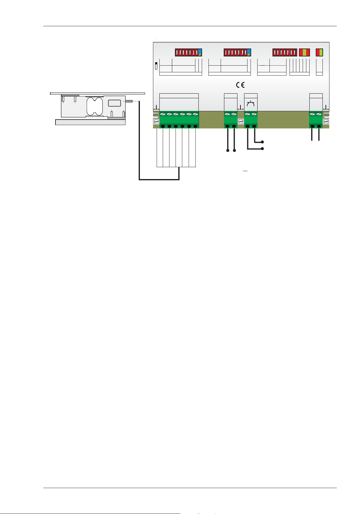
Typical Platform 600 x 600 mm
Off
On
0
IN
mV
0,5
1,0
0
%at
2mV/V
SET ZERO Pot ccw = calib.
5
2,5
FLINTEC
LOAD CELLS 10Vdc 100mA
Exc
Inp Inp Sen
Sen
+++
Shield
+Excitation
_
+Sense
+Signal
-Signal
4,0
8,0
2,0
16,0
10
40
20
80
Exc
__
-Sense
-Excitation
Relative
gain
*
Resolu.
1000 n
Pol. +/-
Fine adj.
*
SET SPAN Pot ccw = calib.
Analog
0/4 ... 20 mA or
0 ... 10 V
0,5
1,0
1,0
0,25
60
50
40
30
Out
20mA/
10V
Gnd
I/V
-+
ue Output
1
33
4,0
8,0
2,0
16,0
7
4
13
20
Fine adj.
10
f
CUT
t
SET
3,3
0,33
5
50
16
ms
FILTER
160
500
0-20/4-20
20mA/10V
OUTPUT
Under
In range.
Over
CND
Error
Pwr. OK
LAC 74.1
Log Err.
U
Gnd
C
Logic Output
Open Collector,
normally closed,
opens at LAC error
PWR
12-24Vdc
GND
+
+12-24 V DC
0V
Manual LAC 74.1 Page 5
 Loading...