

Page 1
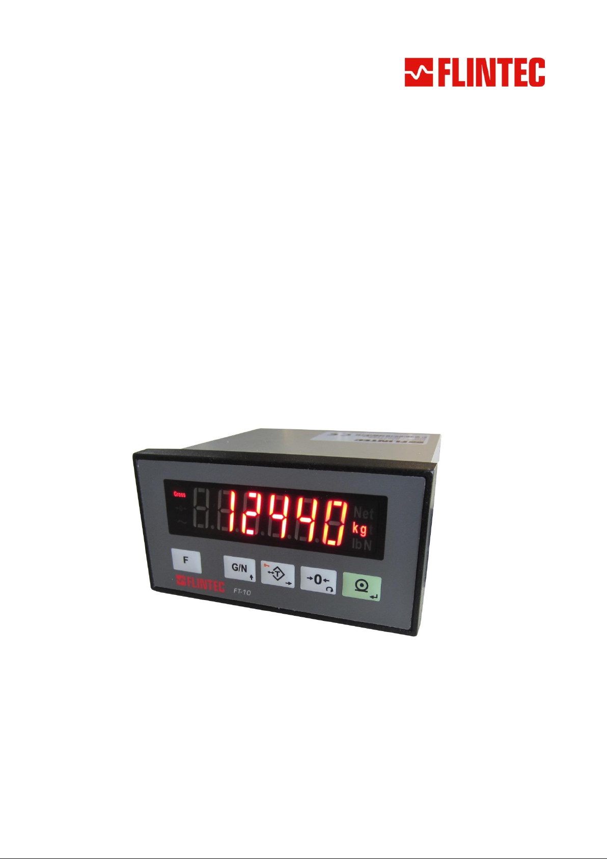
Weight Indicator
FT-10P / FT-10xx
Smart Process Indicator
Technical Manual
Flintec GmbH
Bemannsbruch 9
74909 Meckesheim
GERMANY
www.flintec.com
Page 2
Page 1 of 92
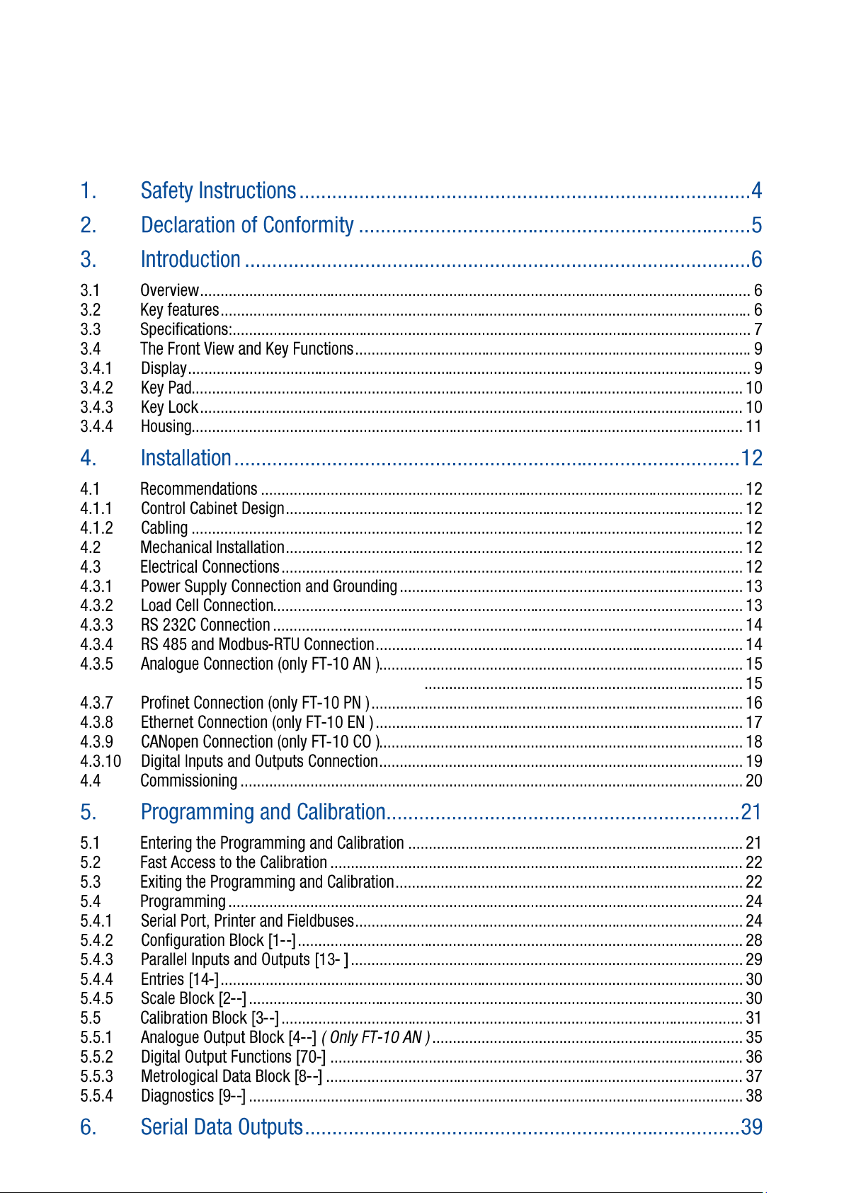
Table Of Contents:
4.3.6 Profibus Connection (only FT-10 PB )
FT-10 Smart Process Indicator, User Manual, Rev. 1.0, January 2014
Page 3

Page 2 of 92
FT-10 Smart Process Indicator, User Manual, Rev. 1.0, January 2014
Page 4

Page 3 of 92
RIGHTS AND LIABILITIES
All rights reserved.
No part of this publication may be reproduced, stored in a retrieval system, or transmitted in any form or
by any means, mechanical, photocopying, recording, or otherwise, without the prior written permission of
FLINTEC GmbH.
No patent liability is assumed with respect to the use of the information contained herein. While every
precaution has been taken in the preparation of this book, FLINTEC assumes no responsibility for errors
or omissions. Neither is any liability assumed for damages resulting from the use of the information
contained herein.
The information herein is believed to be both accurate and reliable. FLINTEC, however, would be obliged
to be informed if any errors occur. FLINTEC cannot accept any liability for direct or indirect damages
resulting from the use of this manual.
FLINTEC reserves the right to revise this manual and alter its content without notification at any time.
Neither FLINTEC nor its affiliates shall be liable to the purchaser of this product or third parties for
damages, losses, costs, or expenses incurred by purchaser or third parties as a result of: accident,
misuse, or abuse of this product or unauthorized modifications, repairs, or alterations to this product, or
failure to strictly comply with FLINTEC operating and maintenance instructions.
FLINTEC shall not be liable against any damages or problems arising from the use of any options or any
consumable products other than those designated as Original FLINTEC Products.
NOTICE: The contents of this manual are subject to change without notice.
Copyright © 2013 by FLINTEC GmbH, 74909 Meckesheim, Bemannsbruch 9, Germany
FT-10 Smart Process Indicator, User Manual, Rev. 1.0, January 2014
Page 5

Page 4 of 92
1. SAFETY INSTRUCTIONS
CAUTION! READ THIS MANUAL BEFORE OPERATING OR SERVICING THIS
EQUIPMENT. FOLLOW THESE INSTRUCTIONS CAREFULLY. SAVE THIS MANUAL
FOR FUTURE REFERENCE. DO NOT ALLOW UNTRAINED PERSONNEL TO
OPERATE, CLEAN, INSPECT, MAINTAIN, SERVICE, OR TAMPER WITH THIS
EQUIPMENT. ALWAYS DISCONNECT THIS EQUIPMENT FROM THE POWER
SOURCE BEFORE CLEANING OR PERFORMING MAINTENANCE. CALL FLINTEC
ENGINEERING FOR PARTS, INFORMATION, AND SERVICE.
WARNING! ONLY PERMIT QUALIFIED PERSONNEL TO SERVICE THIS EQUIPMENT.
EXERCISE CARE WHEN MAKING CHECKS, TESTS AND ADJUSTMENTS THAT MUST
BE MADE WITH POWER ON. FAILING TO OBSERVE THESE PRECAUTIONS CAN
RESULT IN BODILY HARM.
WARNING! FOR CONTINUED PROTECTION AGAINST SHOCK HAZARD CONNECT
TO PROPERLY GROUNDED OUTLET ONLY. DO NOT REMOVE THE GROUND
PRONG.
WARNING! DISCONNECT ALL POWER TO THIS UNIT BEFORE REMOVING ANY
CONNECTION, OPENING THE ENCLOSURE OR SERVICING.
WARNING! BEFORE CONNECTING/DISCONNECTING ANY INTERNAL ELECTRONIC
COMPONENTS OR INTERCONNECTING WIRING BETWEEN ELECTRONIC
EQUIPMENT ALWAYS REMOVE POWER AND WAIT AT LEAST THIRTY (30)
SECONDS BEFORE ANY CONNECTIONS OR DISCONNECTIONS ARE MADE.
FAILURE TO OBSERVE THESE PRECAUTIONS COULD RESULT IN DAMAGE TO OR
DESTRUCTION OF THE EQUIPMENT OR BODILY HARM.
CAUTION! OBSERVE PRECAUTIONS FOR HANDLING ELECTROSTATIC SENSITIVE
DEVICES.
FT-10 Smart Process Indicator, User Manual, Rev. 1.0, January 2014
Page 6

Page 5 of 92
2. DECLARATION OF CONFORMITY
EG-Konformitätserklärung
EC-Declaration of Conformity
Monat/Jahr: month/year:
07/2013
Hersteller: Manufacturer:
Flintec GmbH
Anschrift: Address:
Bemannsbruch 9
D-74909 Meckesheim
Deutschland / Germany
Produktbezeichnung: Product name:
FT-10 Wäge-Indikator / FT-10 Weight Indicator
Das bezeichnete Produkt stimmt mit folgenden Vorschriften der Europäischen Richtlinien überein:
This product confirms with the following regulations of the Directives of the European Community
Richtlinie 2004/108/EG des Europäischen
Parlaments und des Rates vom 15. Dezember 2004
zur Angleichung der Rechtsvorschriften der
Mitgliedstaaten über die elektromagnetische
Verträglichkeit und zur Aufhebung der Richtlinie
89/336/EWG
Directive 2004/108/EC of the European Parliament and of the
Council of 15th December 2004 on the approximation of the
laws of the Member States relating to electromagnetic
compatibility and repealing Directive 89/336/EEC
Richtlinie 2006/95/EG Niederspannungs-Richtlinie
Directive 2006/95/EC Low Voltage Directive
Die Absicherung aller produktspezifischen
Qualitätsmerkmale erfolgt auf Basis eines zertifizierten
Qualitätsmanagement-Systems nach DIN ISO 9001.
All product-related features are assured by a quality
system in accordance with ISO 9001.
Diese Erklärung bescheinigt die Übereinstimmung mit
den genannten Richtlinien, beinhaltet jedoch keine
Zusicherung von Eigenschaften.
This declaration certifies the conformity with the listed
directives, but it is no promise of characteristics.
Folgende Normen werden zum Nachweis der Übereinstimmung mit den Richtlinien eingehalten:
As a proof of conformity with the directives following standards are fulfilled:
EN 61326-1
Elektrische Mess-, Steuer-, Regel- und Laborgeräte - EMV-Anforderungen - Teil 1: Allgemeine
Anforderungen (IEC 61326-1:2005)
Electrical equipment for measurement, control and laboratory use - EMC requirements - Part 1: General
requirements (IEC 61326-1:2005)
EN 60950-1
Einrichtungen der Informationstechnik - Sicherheit - Teil 1: Allgemeine Anforderungen (IEC 609501:2005, modifiziert);
Information technology equipment - Safety - Part 1: General requirements (IEC 60950-1:2005 modified)
FT-10 Smart Process Indicator, User Manual, Rev. 1.0, January 2014
Page 7
3. INTRODUCTION
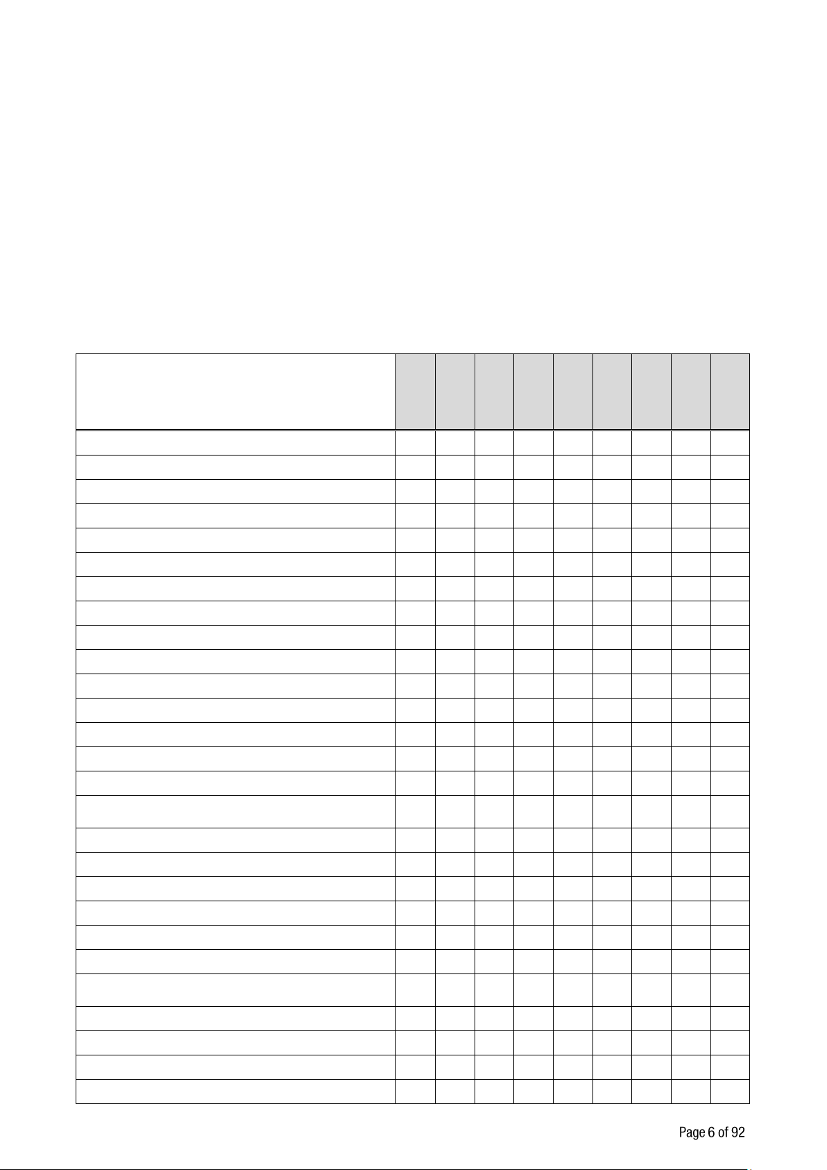
FT-10
FT-10P
FT-10IO
FT-10AN
FT-10MB
FT-10PB
FT-10PN
FT-10EN
FT-10CO
1 000 to 999 999 display resolution
X X X X X X X X X
High internal resolution up to 16 000 000 counts
X X X X X X X X X
Up to 1600 conversion per second
X X X X X X X X X
Serial interface RS 232C
X X X X X X X X X
Serial interface RS 485
- X X X X X X X X
Analogue output
- - - X - - - - -
Profibus DPV1 interface
- - - - - X - - -
Profinet interface
- - - - - - X - -
Ethernet interface
- - - - - - - X -
CANopen interface
- - - - - - - - X
Continuous data output
X X X X X X X X X
Fast Continuous data output
X X X X X X X X X
BSI data interface
X X X X X X X X X
Modbus RTU
- - - X X X X X X
Modbus TCP
- - - - - - - X -
2 programmable digital input/output
(non-isolated)
X X - - - - - - -
2 digital input and 4 relay contact output
- - - X - - - - -
4 digital input and 5 relay contact output
- - X - X X X X X
Bidirectional signal input for force measurement
X X X X X X X X X
Unit selection (g, kg, t, lb, klb, N, kN )
X X X X X X X X X
Peak function
- - X X X X X X X
Hold function
- - X X X X X X X
Auto-zero tracking and auto-zero at
power-up
X X X X X X X X X
Motion detection
X X X X X X X X X
Zeroing and Taring via interface
X X X X X X X X X
Adaptive digital filter for faster measuring
X X X X X X X X X
Electronic calibration (eCal) without test weights
X X X X X X X X X
3.1 Overview
FT-10 family instruments are economic and powerful state-of-the-art technology indicators for weighing and
force measurements. These instruments convert the low level strain gage load cell analog signal to digital
signal in high resolution and accuracy to transmit digital data to PLC or PC. With a wide variety of interface,
FT-10 instruments are used for any type of weighing processes and force measurement including tank and
silo weighing, dynamic weighing, check weighing, filling, tension /compression force measurement etc.
3.2 Key features
FT-10 Smart Process Indicator, Technical Manual, Rev. 1.0, January 2014
Page 8
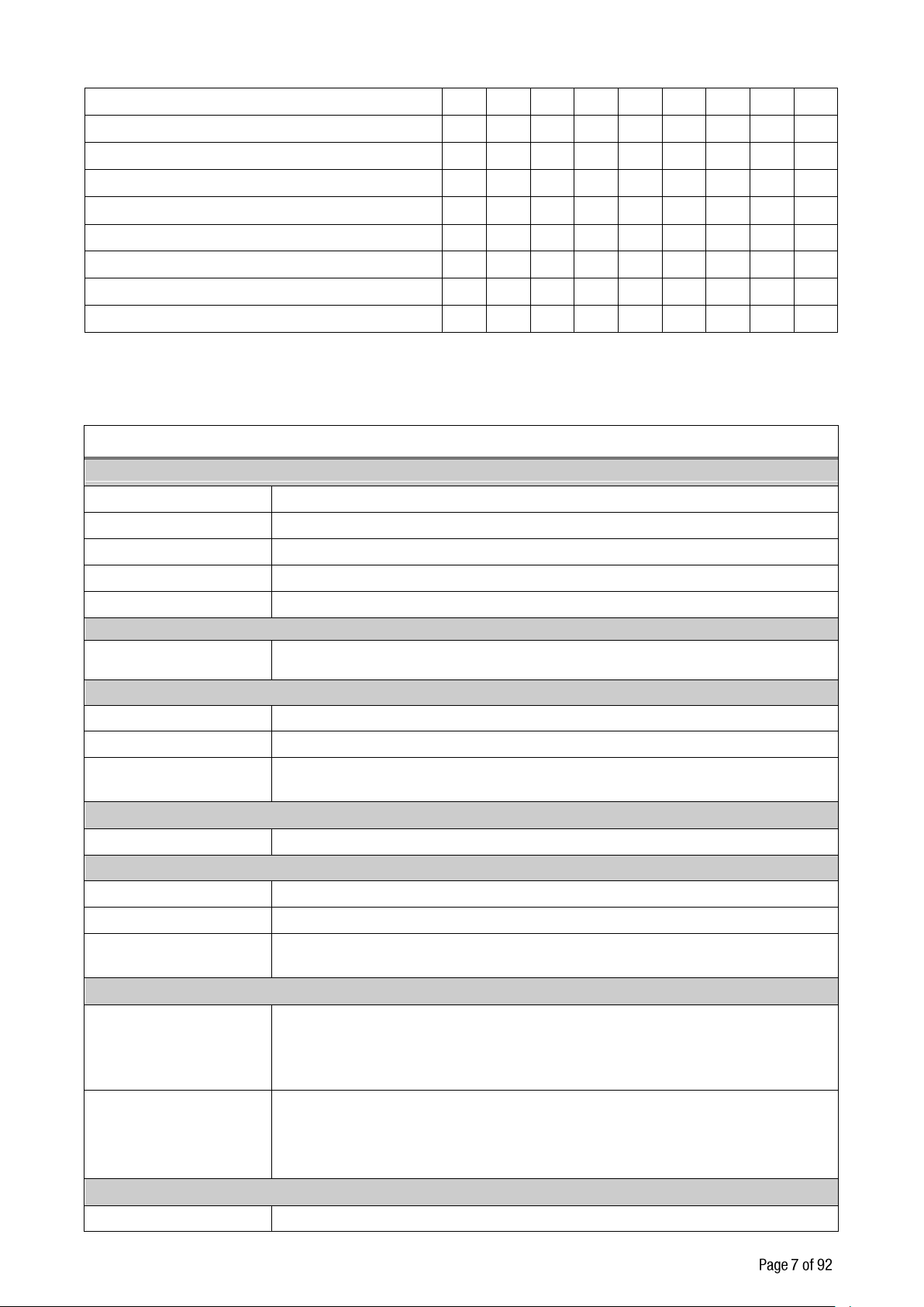
Common Specifications
A/D Converter
A/D converter type
24 bit Delta-Sigma radiometric with integral analog and digital filters
Conversion rate
Up to 1600 measurement values per second
Input sensitivity
0.1 μV/d (non approved)
Analog input range
0 mV to +18 mV ( unipolar ) ;
- 18 mV to +18 mV ( bipolar )
Internal resolution
up to 16 000 000
External Resolution
Display resolution
up to 999 999 increment
Scale Calibration and Functions
Calibration
Calibration is performed with or without test weights ( eCal )
Digital filter
10 steps programmable adaptive filter
Weighing functions
Taring, zeroing, auto zero tracking, motion detection, auto zero at power up, net
indication at power on, increased resolution
Linearity
Within 0.0015% FS, 2 ppm/°C
Load cells
Excitation
5 VDC max. 300 mA
Number of load cells
Up to 8 load cells 350 Ω or 18 load cells 1100 Ω in parallel
Connection
4- or 6-wire technique.
Cable length: maximum 250 m/mm² for 6-wire connection
Digital Inputs and Outputs
Digital Inputs
2 optoisolated digital inputs at FT-10 AN,
4 optoisolated digital inputs at FT -10, FT-10 MB, FT-10 PB, FT-10 PN, FT-10
EN, FT-10 CO;
12 to 28 VDC, 10mA
Digital Outputs
4 free relay contact at FT-10 AN,
5 free relay contact at FT-10, FT-10 MB, FT-10 PB, FT-10 PN, FT-10 EN, FT-10
CO
250 VAC or 30 VDC , 1A
Power consumption
12 to 28 VDC max. 300 mA
Electronic calibration (eCal) over field bus
- - - X X X X X X
Zero and Span calibrations over field bus
- - - X X X X X X
Zero adjustment
X X X X X X X X X
Span adjustment with test weights
X X X X X X X X X
Span adjustment for filled tanks
X X X X X X X X X
3 point calibration ( linearity correction )
X X X X X X X X X
Programming by IndFace PC software
X X X X X X X X X
8 load cells 350 Ω or 18 load cells 1100 Ω
X X X X X X X X X
12 to 28 VDC power supply range
X X X X X X X X X
3.3 Specifications:
FT-10 Smart Process Indicator, Technical Manual, Rev. 1.0, January 2014
Page 9
Environment and Enclosure
Operation temperature
-10 °C to +40 °C; 85% RH max, non-condensing
Enclosure
Panel type, front and rear panel are stainless steel; Aluminum body
Protection
Front panel IP65
FT-10 AN Analogue
Communication
Voltage output
0-5 VDC, 0-10 VDC
Current output
4-20mA, 0-20mA
D/A Converter
16 bit
Max. cable length
300 meter
Max. load resistance
(current output )
500 Ω
FT-10 MB Modbus-RTU
Communication
RS-485
1200 to 115200 baudrate, 8N1 / 7E1 / 7O1
Response speed
Up to 4 ms response delay after read/write commands
Max Stations
Up to 31 stations per segment
FT-10 PB Profibus DPV1
Communication
Data rate
Up to 12000 kbit/s with automatic baud rate detection
GSD file
Generic GSD-file provided
Topology
Depending on physical media
RS-485: segmented line topology without stubs
Installations
Shielded twisted pair cable
Line length depending on physical media and transmission speed
Max. Stations
Up to 32 stations per segment, up to 126 stations per network
Isolation
Galvonically isolated bus electronics
Response speed
Up to 4 ms response delay after read/write commands
FT-10 PN Profinet
Communication
Data rate
100 Mbit/s, full duplex
GSDML file
Generic GSDML-file provided
TCP/IP settings
DHCP or manual IP assign over EtherX PC Software.
Device identity customization
Topology
Line, Bus, Star or Tree topology depending on physical media
Installation
Switched Ethernet transmission with shielded twisted pair cables and RJ-45
connectors.
Web client
Available
Isolation
Galvonically isolated bus electronics
Response speed
Up to 4 ms response delay after read/write commands
FT-10 Smart Process Indicator, Technical Manual, Rev. 1.0, January 2014
Page 10

FT-10 EN Ethernet
Communication
Transmission rate
10 Mbit/s, half duplex
TCP/IP settings
Manual IP assign over EtherX PC Software
Installation
Switched Ethernet transmission with shielded twisted pair cables and RJ-45
connectors.
Web client
Available
Response speed
Up to 4 ms response delay after read/write commands
FT-10 CO CANopen
Communication
Data rate
10 kbit/s – 1 Mbit/s (selectable) kbit/s
ESD file
Generic EDS-file provided
Topology
Line with Trunkline, Dropline structure and Termination at both Ends
Line length depending on baudrate 25 – 500 meter.
Installation
2 wire shielded twisted pair cable
Alternatively 4 wire with 24 Volt power over the bus
Max. Stations
Up to 127 stations per network
Isolation
Galvonically isolated bus electronics
Response speed
Up to 4 ms response delay after read/write commands
3.4 The Front View and Key Functions
Figure 3.1 - Front panel view of FT-10
3.4.1 Display
The weight display of FT-10 is seven segments LED. At the right side of the display there are two LED’s for
indicating the net and the unit ( standard kg ), also the left side of the display for indicating the gross, center
of zero and unstable.
FT-10 Smart Process Indicator, Technical Manual, Rev. 1.0, January 2014
Page 11
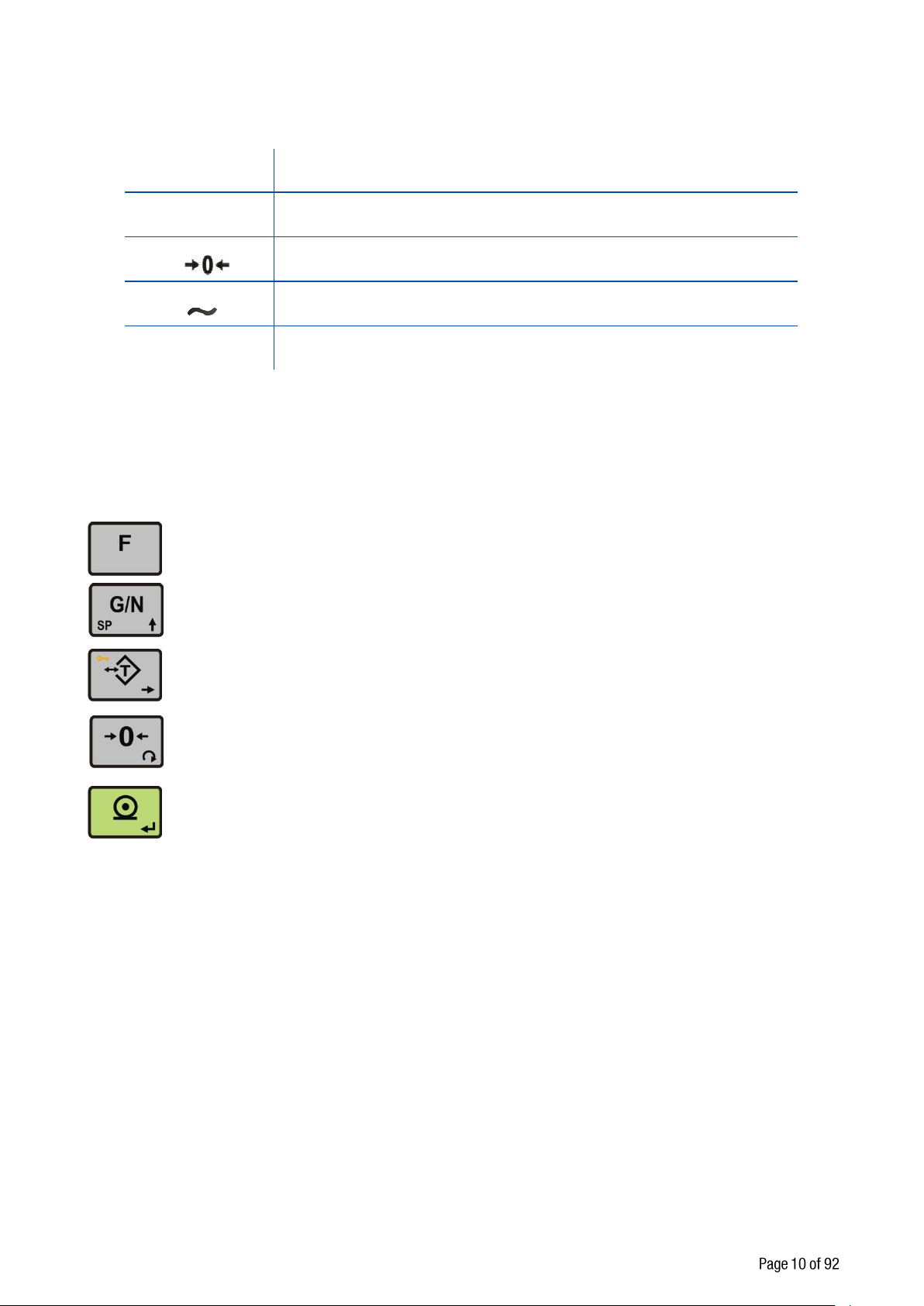
The meanings of the announcement LED’s on the display are:
Gross
Announces the indicated value is the gross weight.
Net
Announces the indicated value is the net weight.
Announces the weight is in the center of zero.
Announces the weight value on the display is unstable.
Units
g, kg, t, lb, klb, N, kN units are located on the right of the display.
3.4.2 Key Pad
The keys and the key functions of FT -10 are:
Function : Key function is programmable to Increased Indication, Total, Tare value indication,
CN value indication, Peak function and Hold function at parameter [ 116 ] (Page 28).
GN / Set Point : Pressing this key indicates the Gross weight temporarily. To enter the set
point menu, long press this key.
Tare / Clear : Pressing this key tares the scale and get into the Net mode.
Zeroing: In Gross mode, if the scale doesn’t show zero while there is no load on the pan, you
can zero the scale by pressing this key.
Print: By pressing this key weight data and other information depending on the setup
parameters sent to a printer or a PC via serial port.
3.4.3 Key Lock
FT-10 has ability to lock the keys to avoid unauthorized person’s interfere. The key(s) which would be locked
are programmed at parameter [ 115 ] (Page 30).
You can activate or deactivate this function by long pressing <F> key, press <Tare/Clear> and <Print> keys
sequentially. [ Lock ] prompt appear for a short while to indicate the pressed key is locked.
FT-10 Smart Process Indicator, Technical Manual, Rev. 1.0, January 2014
Page 12
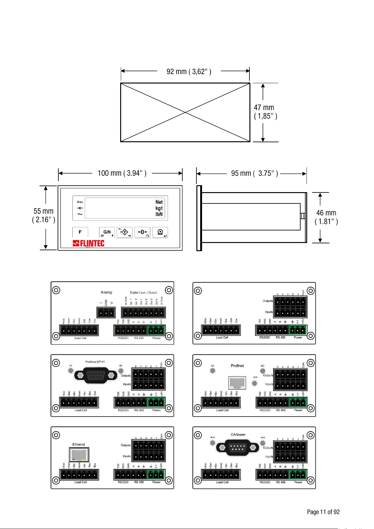
3.4.4 Housing
FT-10 AN Panel type rear view
FT-10 & FT-10 MB Panel type rear view
FT-10 PB Panel type rear view
FT-10 PN Panel type rear view
FT-10 EN Panel type rear view
FT-10 CO Panel type rear view
FT-10P
FT-10 housings are panel type with stainless steel front and back parts, and aluminium body.
The hole dimensions for mounting FT-10 on the panel
FT-10 front and side view
FT-10 Smart Process Indicator, Technical Manual, Rev. 1.0, January 2014
Page 13

4. INSTALLATION
PRECAUTION: Please read this section carefully before installation of the instrument. Applying the
recommendations in this section will increase your system reliability and long term performance.
4.1 Recommendations
Please follow the installation and commissioning steps described below carefully to prevent unwanted results
after installation.
4.1.1 Control Cabinet Design
Warning: Please care the following warnings for designing the control cabinet which will increase your
system reliability.
The control cabinet should be designed so that Analog Digitizer can operate safely. The panel should be
placed in a clean area, not getting direct sun light if possible, with a temperature between -10 ºC and +40 ºC,
humidity not exceeding 85% non-condensing. All external cables should be installed safely to avoid
mechanical damages.
FT-10 instruments are very low level signal measuring instruments. To avoid electrical noise, FT-10 should
be separated from the equipments that produce electrical noise. Preferable use metal cabinet against radio
frequency interference and the cabinet shall be connected to ground against the electromagnetic
disturbances. Load cell cable trays must be separated from others, if possible. If there are noise-generating
equipments such as heavy load switches, motor control equipments, inductive loads etc., please be careful
against the EMC interference in the cabinet. If possible protect FT-10 instruments with the faraday cage or
install them in separate section or install them far away from this kind of equipments. Connect parallel
reverse diodes to the DC inductive loads like relays, solenoids etc. to minimize voltage peaks on the DC
power lines.
4.1.2 Cabling
All cables coming to the control cabinet shall be shielded. Please use separate cable tray for these low
signal level cables. Distance from load cell cables, interface cables and DC power supply cables to power
line cables shall be minimum 50 cm.
4.2 Mechanical Installation
Take care to the housing dimensions and the suggested panel hole dimensions given in the Page 11. To
avoid electrical noises, protect your indicator which has very low input signal level from the equipment that
produces electrical noise in panel mounting.
4.3 Electrical Connections
Warning: Please always remember that FT-10 instruments are very low voltage measuring instruments.
Your control cabinet design and proper installation increases reliability and performance of the instrument.
Please do not forget that the instrument must be powered off before inserting or removing any peripheral
connector.
The electrical installation and quality of instrument’s grounding will provide weighing accuracy and the safety
of your indicator. If the energy condition of your plant is bad, prepare a special power line and grounding. All
required electrical connections should be done as described below.
If you have to service the indicator, turn the power off and wait at least 30 seconds before interfering.
FT-10 Smart Process Indicator, Technical Manual, Rev. 1.0, January 2014
Page 14

4.3.1 Power Supply Connection and Grounding
The pin layout of the 24 VDC
connector of FT-10 Series
( rear view )
0V 24V
4 wire LC connection
6 wire LC connection
Power supply voltage of the instrument shall be between 12 VDC and 28 VDC. The pin configuration of the
24 VDC power supply connector located right - bottom of the instrument is shown in Figure 4.1 below.
The quality of the instrument’s ground will determine the accuracy and the safety of your measuring system.
A proper ground connection is needed to minimize extraneous electrical noise effects on the measurement.
A poor ground can result in an unsafe and unstable operation. It is important that the instrument should not
share power lines with noise-generating parts such as heavy load switching relays, motor control equipment,
inductive loads, etc. If the condition of the power line in the plant is poor, prepare a special power line and
grounding.
Before interfering the instrument, turn off the power and wait at least for 30 seconds.
Warning: Connect the Shield pin to the reference ground.
Figure 4.1 - The pin layout of 24VDC connector
4.3.2 Load Cell Connection
To avoid damages, the load cell wiring should be made carefully before energizing the instrument. Load cell
connection detail is shown in Figure 4.2
In 4-wire installations the sense and excitation pins with the same polarity should be short circuited at the
connector side. If you have junction box, use 6 wire cable between FT-10 and the junction box, and short
circuit these pins at junction box for better performance.
Warning: Always connect Sense pins to Excitation pins for 4 wire connection. Non-connected sense pins
may cause the wrong Excitation voltage measurement and create an accuracy problem.
Warning: Connect the load cell cable shield to the reference ground or shield pin of the load cell
connector.
FT-10 Smart Process Indicator, Technical Manual, Rev. 1.0, January 2014
Figure 4.2 - Load cell connections
Page 15
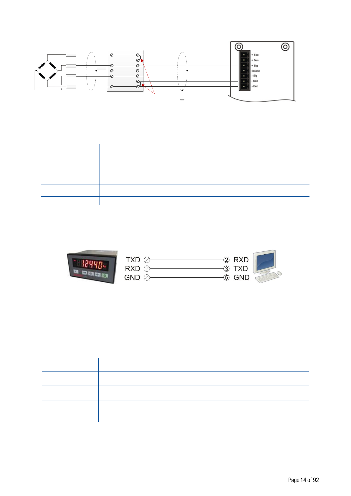
Junction box 6 Wire-cable FT-10 Indicator
Bridges
4W-Load cell
Shield
Shield
+ Exc
+ Sig
- Sig
- Exc
Shield
Usage
Interfacing with PC or PLC, remote display connection,
programming via IndFace1X
Data formats
Continuous, Fast Continuous, Printer Format, BSI Protocol,
Modbus-RTU High-Low, Modbus-RTU Low-High
Baud rate
1200 / 2400 / 4800 / 9600 (Default) / 19200 / 38400 / 57600 / 115200 bps
Length and parity
8 bit no parity (Default), 7 bit odd, 7 bit even
Start / Stop bits
1 start bit and 1 stop bit
Usage
Interfacing with PC or PLC, remote display,
programming via IndFace1X,
Data formats
Continuous, Fast Continuous, Printer Format, BSI Protocol,
Modbus-RTU High-Low, Modbus-RTU Low-High
Baud rate
1200 / 2400 / 4800 / 9600 (Default) / 19200 / 38400 / 57600 / 115200 bps
Length and parity
8 bit no parity (Default), 7 bit odd, 7 bit even
Start / Stop bits
1 start bit and 1 stop bit
4.3.3 RS 232C Connection
RS 232C port usage and specifications are shown in the table 4.1
RS 232C serial connection is done with three wire as indicated below.
Warning: Connecting the shield to the reference ground will protect your weighing system against EMC
disturbances.
Table 4.1 – RS 232C Serial Interface Specifications
Figure 4.3 - RS 232C serial interface connections
4.3.4 RS 485 and Modbus-RTU Connection
RS 485 port usage and specifications are shown in the table below ( Page 25 ).
RS 485 serial connection is done with three wire as indicated in Figure 4.4. Line termination resistors ( 110
ohm ) are needed both ends of the RS 485 line.
FT-10 Smart Process Indicator, Technical Manual, Rev. 1.0, January 2014
Table 4.2 - RS 485 Serial Interface Specifications
Page 16
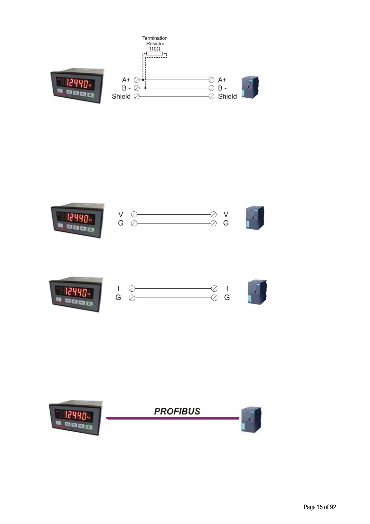
Figure 4.4 – RS 485 serial interface connections
Warning: Connect the shield to the reference ground.
Warning: Disconnect IndFace1X PC software before starting Modbus-RTU interfacing.
4.3.5 Analogue Connection (only FT-10 AN )
FT-10AN is programmable to 4 – 20 mA, 0 – 20 mA, 0 – 5 V or 0 – 10 V analogue output types.
Analogue connections are done as indicated in Figure 4.5 and Figure 4.6
Figure 4.5 - FT-10 AN Voltage output connections
Figure 4.6 - FT-10 AN Current output connections
4.3.6 Profibus Connection (only FT-10 PB )
Profibus connection is done as indicated in Figure 4.7.
Figure 4.7 - FT-10 PB serial interface connections
FT-10 Smart Process Indicator, Technical Manual, Rev. 1.0, January 2014
Page 17
PROFIBUS Connector pin configuration (DB9F)
Pin
Signal
Description
1
- - 2
-
-
3
B Line
Positive RxD / TxD, RS-485 level
4
RTS
Request to send
5
GND Bus
Ground (isolated)
6
+5V Bus Output
+5V termination power (isolated)
7
- - 8
A Line
Negative RxD / TxD, RS-485 level
9
- - Housing
Cable Shield
Ground
Pin
Signal
DIR
Description
1
TX+
Out
Differential Ethernet transmit data +
2
TX−
Out
Differential Ethernet transmit data −
3
RX+
In
Differential Ethernet receive data +
6
RX−
In
Differential Ethernet receive data −
4
Not used
Terminated
5
Not used
Terminated
7
Not used
Terminated
8
Not used
Terminated
Shield
Chasis ground
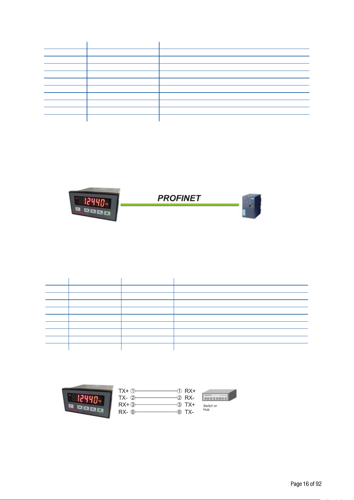
4.3.7 Profinet Connection (only FT-10 PN )
Profinet connection is done as indicated in Figure 4.8.
Figure 4.8 - FT-10 PN serial interface connections
PROFINET Connector pin configuration (RJ45)
The HUB connection cabling will be a direct connection as shown in Figure 4.9:
The PC connection cabling will be done via cross cable as shown below. IP address blocks and gateway
address of FT-10 and PC should be the same in cross connection.
FT-10 Smart Process Indicator, Technical Manual, Rev. 1.0, January 2014
Figure 4.9 - HUB connection
Page 18
Usage
Ethernet interface with PC or PLC
Data formats
Continuous, Fast Continuous, Printer Format, BSI Protocol,
Modbus TCP/IP High-Low,
Modbus TCP/IP Low-High
Ethernet
The Ethernet interface operates at 10Mbit, half duplex
Pin
Signal
DIR
Description
1
TX+
Out
Differential Ethernet transmit data +
2
TX−
Out
Differential Ethernet transmit data −
3
RX+
In
Differential Ethernet receive data +
6
RX−
In
Differential Ethernet receive data −
4
Not used
Terminated
5
Not used
Terminated
7
Not used
Terminated
8
Not used
Terminated
Shield
Chassis ground
Warning: Connect the shield to the reference ground or shield pin of the power connector.
Warning: Disconnect IndFace1X PC software before starting Profinet interfacing.
Figure 4.10 - Cross PC connection
4.3.8 Ethernet Connection (only FT-10 EN )
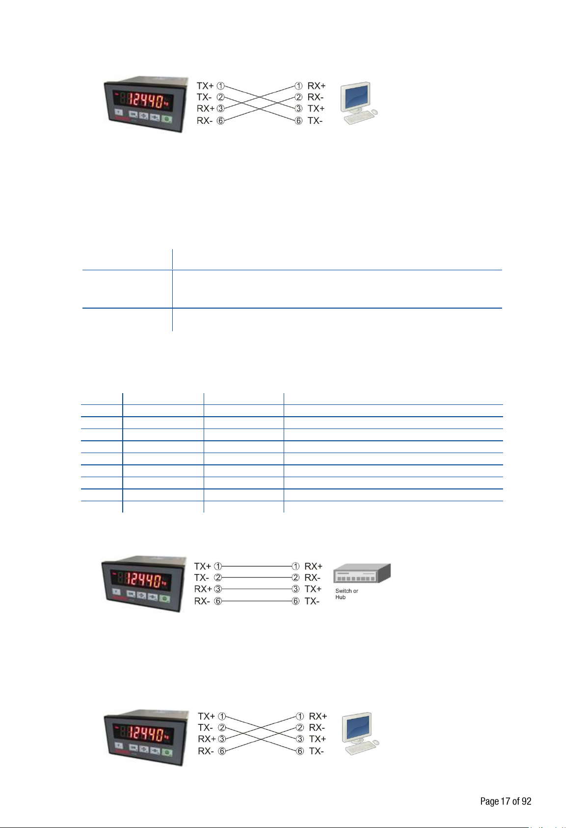
Ethernet interface is used for data transfer to PC or PLC in the formats shown below.
Ethernet Connector pin configuration (RJ45)
The HUB connection cabling will be a direct connection as shown below:
Figure 4.11 - HUB connection
The PC connection cabling will be done via cross cable as shown below. IP address blocks and gateway
address of FT-10 and PC should be the same in cross connection.
Figure 4.12 - Cross PC connection
FT-10 Smart Process Indicator, Technical Manual, Rev. 1.0, January 2014
Page 19
Warning: Connect the shield to the reference ground or shield pin of the power connector.
Pin
Signal
Description
1
-
-
2
CAN_L - 3
CAN_GND
- 4 -
-
5
CAN_SHIELD
- 6 - - 7
CAN_H
- 8 - - 9
- - Housing
Cable Shield
-
Warning: Disconnect IndFace1X PC software before starting Ethernet interfacing.
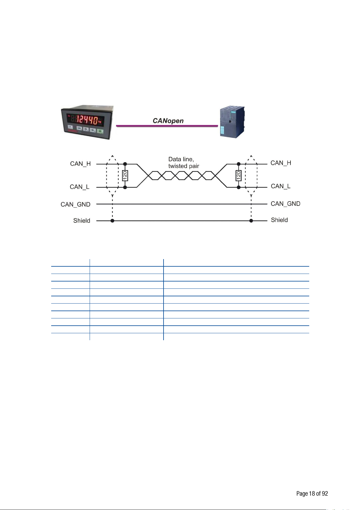
4.3.9 CANopen Connection (only FT-10 CO )
CANopen connection is done with 4 wires as indicated in Figure 4.13. The data line ends must be equipped
with 120 ohm bus terminating resistors.
Figure 4.13 - FT-10 CO serial interface connections
CANopen Connector pin configuration (DB9M)
Warning: Connect the shield to the reference ground.
Warning: Disconnect IndFace1X PC software before starting CANopen interfacing.
FT-10 Smart Process Indicator, Technical Manual, Rev. 1.0, January 2014
Page 20
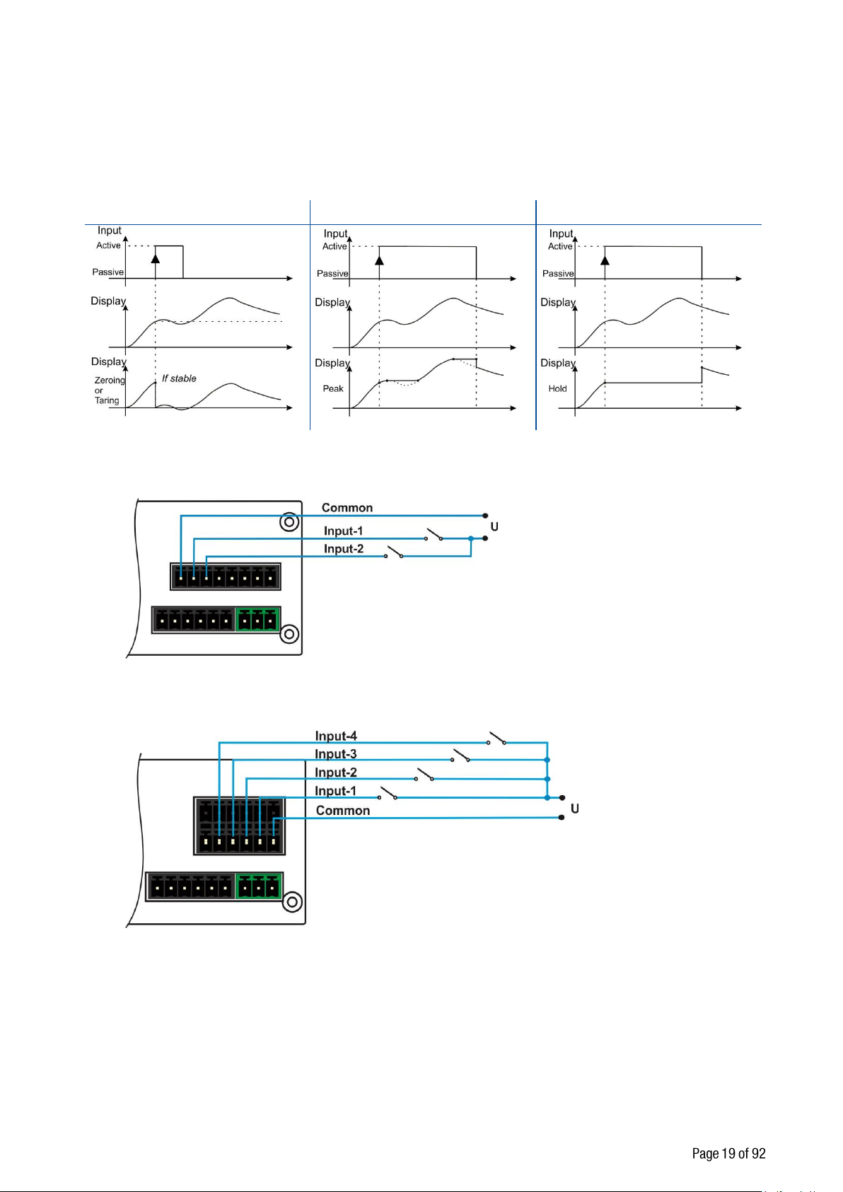
4.3.10 Digital Inputs and Outputs Connection
FT-10 AN
FT-10,
FT-10 MB,
FT-10 PB,
FT-10 PN,
FT-10 EN,
FT-10 CO
Zero or Tare functions :
Peak function :
Hold function :
Digital Inputs:
FT-10 inputs are independently programmable for zeroing, taring, clear, print, key lock, peak, hold, and as a
fieldbus input port. If the input is programmed as a fieldbus input port, the input status is transferred to the
PLC by fieldbus command. Inputs are 12 .. 28 VDC, 10 mA.
Inputs connection diagram is shown in Figure 4.14.
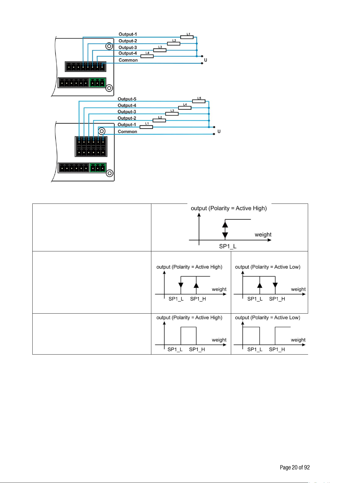
Digital Outputs:
FT-10 instruments digital outputs are can be used as a standard, threshold and window. Threshold and
window outputs are also programmable positive or negative polarity. Digital outputs of FT-10 are also
programmable as a fieldbus port to control them with a fieldbus commands. Refer to parameter [ 130 ] on
Page 29 and [ 70- ] on Page 36 . Outputs are 250 VAC or 30 VDC, 1A.
Outputs connection diagram is shown in Figure 4.16
FT-10 Smart Process Indicator, Technical Manual, Rev. 1.0, January 2014
Figure 4.15 - FT-10 Inputs connection diagram
Page 21
FT-10 AN,
FT-10,
FT-10 MB,
FT-10 PB,
FT-10 PN,
FT-10 EN,
FT-10 CO
Standard Output:
Only one set point value is entered. The
output state is forced active high when the
weight is higher than SP1, else the output is
passive.
Refer to parameter [ 131 ] on Page 29.
Threshold Output:
2 set point values are entered. SP1 is the
point that the output goes active when the
weight increased from SP1_H. SP1_L is the
point that the output drops to passive state
when the weight decreased to SP1_L.
Inverse function is available.
Refer to parameter [ 7-- ] on Page 36.
Window Output:
2 set point values are entered. The output is
active when the weight is between SP1_L
and SP1_H. Inverse function is available.
Refer to parameter [ 7-- ] on Page 36.
Figure 4.16 - FT-10 Outputs connection diagram
4.4 Commissioning
PRECAUTION: Please read this manual carefully before energizing the instrument. Perform the
commissioning operation according the procedure given in this section. Only trained person is allowed for
cleaning, commissioning, checking and servicing of the instrument. The interference of untrained person
may cause some unwanted damages or injuries.
Before power on the instrument, please make the required mechanical and electrical installations. After
power on, you have to program your FT-10 before field bus interfacing.
Install IndFace1X to your PC. IndFace1X software is used for easy programming, calibration and testing of
FT-10 instruments.
After checking the performance of instruments with IndFace1X, you can begin to use FT-10 in your
application.
FT-10 Smart Process Indicator, Technical Manual, Rev. 1.0, January 2014
Page 22
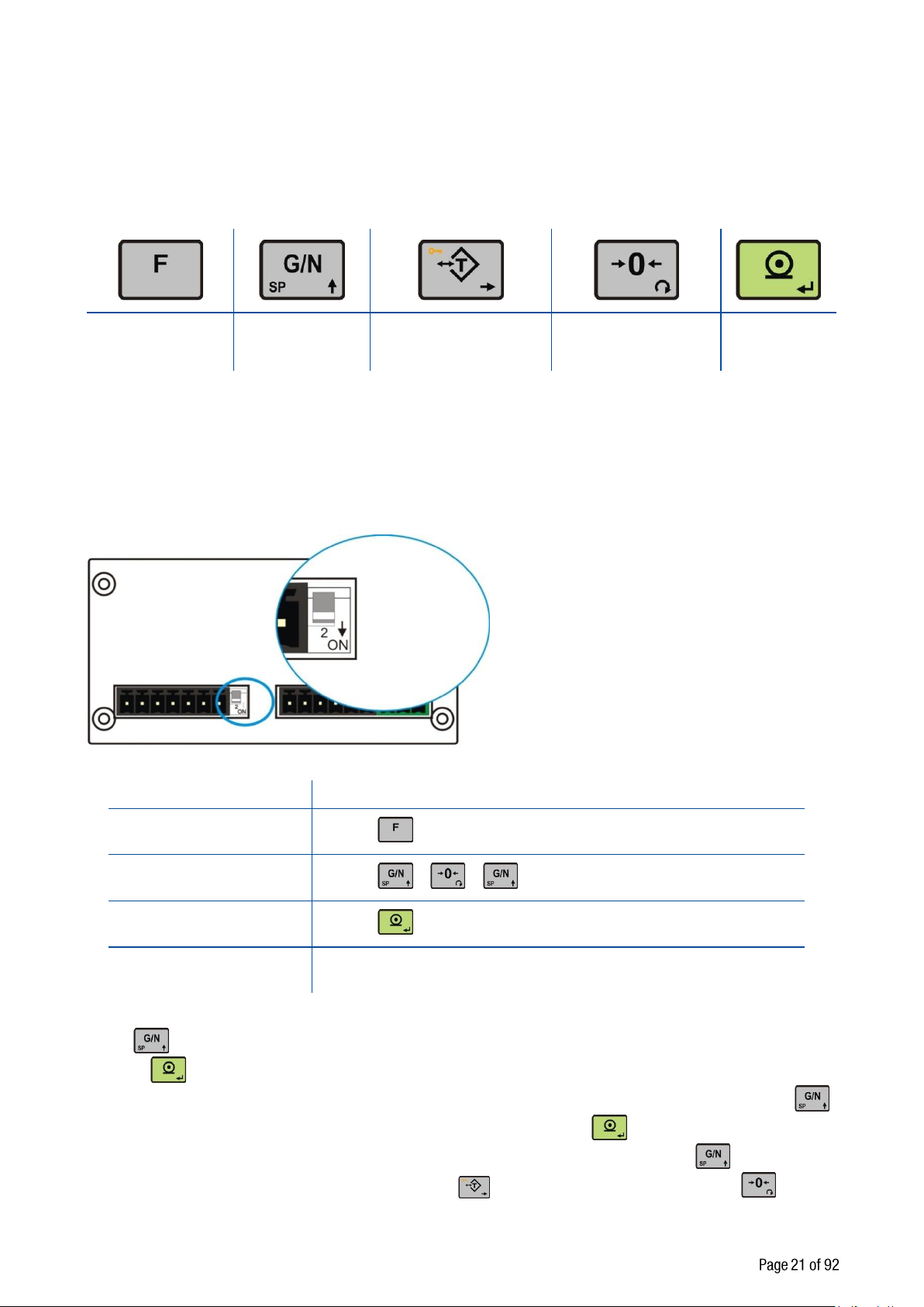
5. PROGRAMMING AND CALIBRATION
Exit without saving
Advancing next
parameter
Select the digit will be
changed
Changing parameter
value or increasing the
blanking digit
Enter
Display
Operation
[123.456 kg]
Press key until [ PASSWr ] prompts seen.
[PASSWr]
Press + + keys sequentially.
[--- ]
Press key for confirm.
[0-- ]
First block of Programming menu.
In this section you will find the programming and calibration procedure of FT-10 indicator according to your
application. The signs those take place on the lower right corner of the keys indicate the function of the keys
in programming menu. The basic meanings of these keys are given the table below.
5.1 Entering the Programming and Calibration
There is a DIP switch on FT-10’s rear side and its position should be “ON” ( downward ) to change the
metrological related parameters including calibration. There is no need to open the housing to change the
position of this DIP switch. If there is not set-up DIP switch on the instrument for industrial usage, its position
is always ON.
Figure 5.1 - The location of calibration DIP switch
Programming and Calibration menu consist of main blocks which are shown as [X-- ] and sub-blocks. By
using key you can reach next main blocks. After reaching the desired main block, you can get in by
pressing key. As you enter the block you will reach the first sub-block in that main block. The sub-block
address will be seen on the display as [X0- ]. You can also search between the sub-blocks by using
key and reach the first parameter of the sub-block seen on the display by key. The number of the
parameter comes on display as [XY0 ]. Again you can search between parameters by key. For
entering numerical value in the parameters, press the key to select the digit and press the key the
change the value.
FT-10 Smart Process Indicator, Technical Manual, Rev. 1.0, January 2014
Page 23
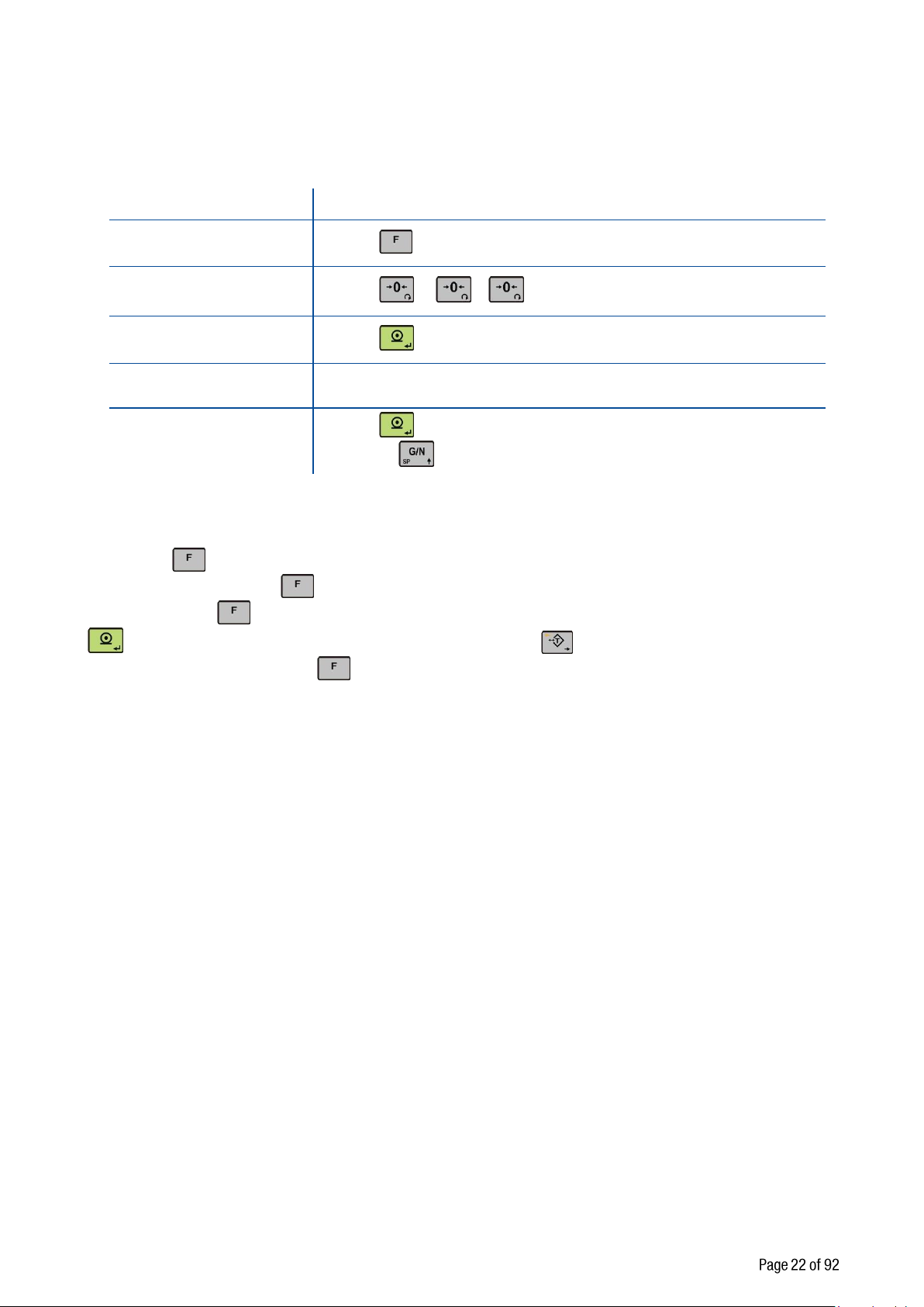
5.2 Fast Access to the Calibration
Display
Operation
[123.456 kg ]
Press key until [ PASSWr ] prompts seen.
[PASSWr]
Press + + keys sequentially.
[ --- ]
Press key for confirm.
[ 310 ]
Zero Adjustment parameter.
“Calibration”
Press key to start zero adjustment.
Or press key to access span calibration without zero adjustment.
The instrument has fast access calibration feature to earn time to the service technician. If only the
calibration adjustment is needed, follow the steps below to access the calibration parameters fast.
5.3 Exiting the Programming and Calibration
If you press key on which parameter you are, you will get out of the active sub-block and reach the
next sub-block. If you press key again, you will get out of the active block and reach the next main
block. If you press key once again, the [ SAvE ] message appears on the display. Here you can press
key to save the changes into the memory, or you can press key to store the changes until the
power goes off, or you can press key to abort changes. [ Waıt ] message will be seen on the display
for a little while, and automatically get back to weighing mode.
Especially for legal metrological usage, please don’t forget to turn the power off and “OFF” position the
calibration DIP switch to start operation.
FT-10 Smart Process Indicator, Technical Manual, Rev. 1.0, January 2014
Page 24
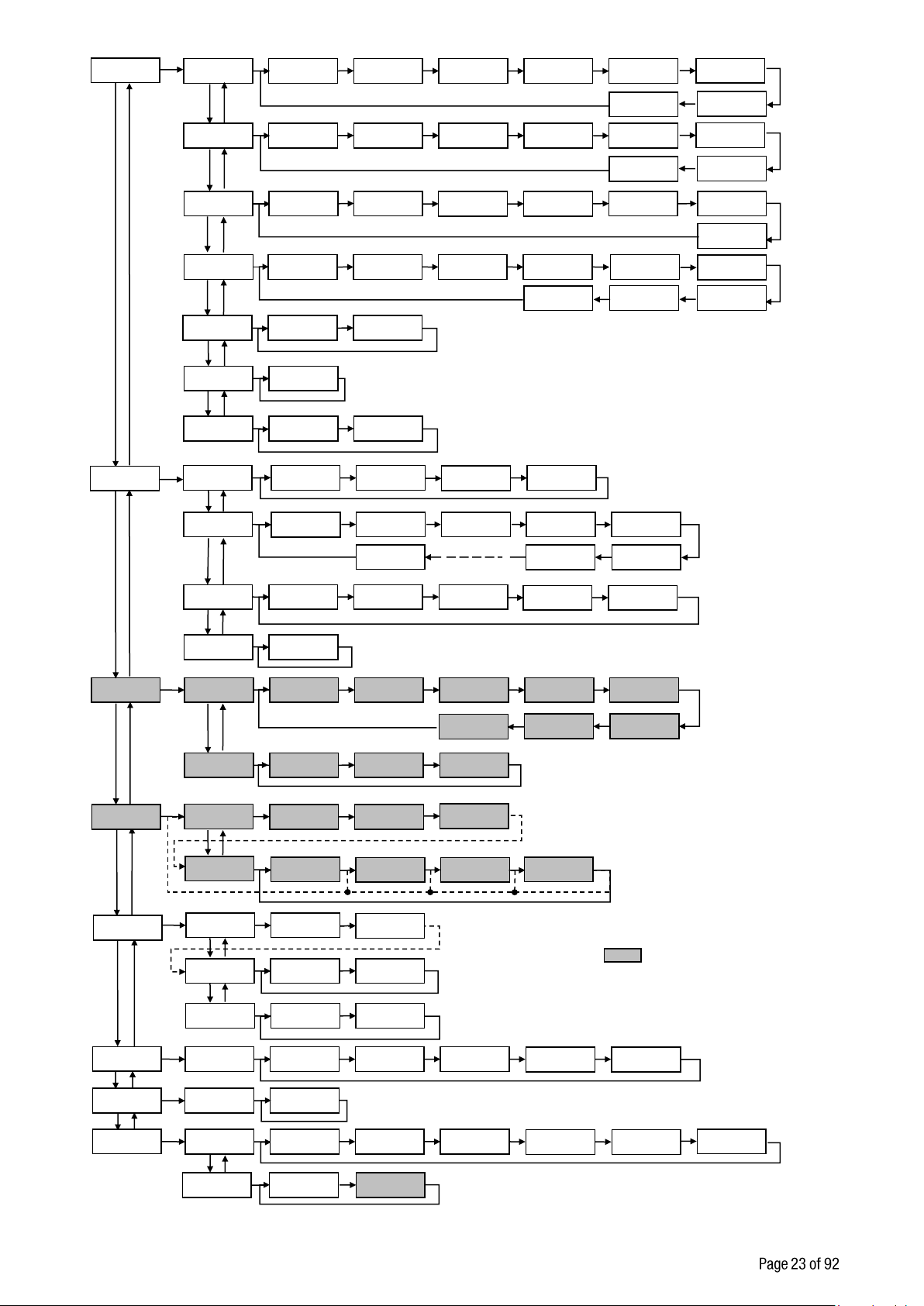
Changeable with calibration
jumper
21 _
WEIGHING
210
W. TYPE
212
CAP1 / d1
214
UNIT
2_ _
SETUP PRMT
20 _
SETUP
200
M.LOGIC
201
DISPLAY
202
PWR ON ZERO
203
ZERO
204
AUTO.ZERO
205
TARE
206
M.DETEC
207
STABILITY
31 _
CAL.ADJ.
311
SPAN CAL.
312
SPAN ADJ CAL
310
ZERO CAL.
313
eCal
30 _
CALIB.
300
GRAVITY
301
CAL.
3_ _
CALIBRATION
302
LINEARITY
4_ _
ANALOGUE
42 _
SPAN ADJ..
420
COARSE
421
FINE
40 _
S.SELECT.
400
MODE
41 _
ZERO CAL.
410
COARSE
411
FINE
401
SET to RANGE
07 _
CANopen
070
FORMAT
071
ADR
04 _
PRINTER
040
P.FORMAT
041
CN
042
MIN. PRT
043
PRT CTRL
044
LF BEFORE P.
046
F.FEED
047
SPC ON LEFT
045
LF AFTER P.
048
Qtity of COPIES
05 _
PROFIBUS
050
FORMAT
051
ADR
06 _
PROFINET
060
FORMAT
0_ _
INTERFACE
01 _
RS 485
010
D.FORMAT
011
BAUD
013
ADR
014
PARITY
015
CHK
016
CR
017
LF
018
RESP. Speed
00 _
RS 232C
000
D.FORMAT
001
BAUD
003
ADR
004
PARITY
005
CHK
006
CR
007
LF
008
RESP. Speed
036
RESP. Speed
03 _
ETHERNET
030
ETH. FORMAT
031
ETH.ADR
032
IP ADR
033
SUB NET MASK
034
GATEWAY
035
LOCAL PORT
14 _
ADJUSTMENT
142
CN
1_ _
CONFIG
11 _
START UP
112
SAVE TARE
113
A. CLR TARE
115
KEY LOCK
116
F KEY FUNC.
120 9
SLOWEST
120 5
12 _
FİLTER
120
F.ADJ
120 0
NO FILTER
120 1
FASTEST
120 2
120 3
120 4
13 _
I / 0
130
OUTPUTS
131
IN1
132
IN2
133
IN3
134
IN4
990
ALL PRMT.
99 _
PRMT. PRT
991
DEFAULT
80 _
RECORDS
800
CAL. COUNT.
8_ _
M.LOGIC REC.
9_ _
CTRL PRMT
90 _
TESTS
900
KEY PAD
901
RS232C
902
RS485
903
INPUTS
904
OUTPUTS
905
mV
704
OUTPUT-5
7_
I/O FUNC.
70_
OUTPUTS
700
OUTPUT-1
701
OUTPUT-2
702
OUTPUT-3
703
OUTPUT-4
FT-10 Smart Process Indicator, Technical Manual, Rev. 1.0, January 2014
Page 25

5.4 Programming
5.4.1 Serial Port, Printer and Fieldbuses
[0--] Interface Block
You can reach the parameters about serial interface of FT-10 indicator in this section. The data output
modes can be used once except continuous data output.
[00-] RS 232C Serial Port
This sub-block includes the parameters about the 1st serial interface of FT-10.
[000 3 ] Data Format
0 : No data transfer.
1 : Continuous data output
2 : Print mode ( Parameter [ 040 ] on Page 26 )
3 : BSI command set ( Page 40 )
4 : Modbus RTU High-Low ( Page 48 )
5 : Modbus RTU Low-High ( Page 48 )
6 : Fast continuous mode ( Page 40 )
( * ) Warning : Use for Flintec remote displays interfacing. CR and LF should be enabled.
[001 3] Baud Rate
0 : 1200 Baud 1 : 2400 Baud 2 : 4800 Baud
3 : 9600 Baud 4 : 19200 Baud 5 : 38400 Baud
6 : 57600 Baud 7 : 115200 Baud
[003 00] Address
You can define a device address between 1 and 99 by this parameter. If you enter 0, indicator will
operate without an address.
[004 0] Data length and parity
0 : 8 bit, no parity 1 : 7 bit, odd parity 2 : 7 bit, even parity
[005 0] Checksum
You can enable or disable for continuous data format and BSI command set.
0 : No checksum 1 : Checksum enable
[006 1] Carriage return
You can enable or disable for continuous data format.
0 : No CR 1 : CR enables (Carriage Return)
[007 1] Line feed
You can enable or disable for continuous data format.
0 : No LF 1 : LF enables (Line Feed)
[008 0] Response Speed
0 : Modbus RTU Answer is sent immediately after Request is received.
1 : Modbus RTU Answer is delayed 20 ms after Request is received.
This property is very helpful for slow PLC systems
( * )
( Page 39 )
FT-10 Smart Process Indicator, Technical Manual, Rev. 1.0, January 2014
Page 26

[01-] RS 485 Serial Interface
This sub-block includes the parameters about the 2nd serial interface of FT-10.
[010 5 ] Data Format
0 : No data transfer.
1 : Continuous data output
2 : Print mode ( Parameter [ 040 ] on Page 26 )
3 : BSI command set ( Page 40 )
4 : Modbus RTU High-Low ( Page 48 )
5 : Modbus RTU Low-High ( Page 48 )
6 : Fast continuous mode ( Page 40 )
( * ) Warning : Use for Flintec remote displays interfacing. CR and LF should be enabled.
[011 3] Baud Rate
0 : 1200 Baud 1 : 2400 Baud 2 : 4800 Baud
3 : 9600 Baud 4 : 19200 Baud 5 : 38400 Baud
6 : 57600 Baud 7 : 115200 Baud
[013 01] Address
You can define a device address between 1 and 99 by this parameter. If you enter 0, indicator will
operate without an address.
[014 0] Data length and parity
0 : 8 bit, no parity 1 : 7 bit, odd parity 2 : 7 bit, even parity
[015 0] Checksum
You can enable or disable for continuous data format and BSI command set.
0 : No checksum 1 : Checksum enable
[016 1] Carriage return
You can enable or disable for continuous data format.
0 : No CR 1 : CR enables
[017 1] Line feed
You can enable or disable for continuous data format.
0 : No LF 1 : LF enables
[018 0] Response Speed
0 : Modbus RTU Answer is sent immediately after Request is received.
1 : Modbus RTU Answer is delayed 20 ms after Request is received.
This property is very helpful for slow PLC systems
( * )
( Page 39 )
FT-10 Smart Process Indicator, Technical Manual, Rev. 1.0, January 2014
Page 27

[03-] Ethernet (Only FT-10 EN)
This sub-block includes the parameters related with the Ethernet of FT -10 indicator.
[030 4 ] Data Format
0 : No data transfer.
1 : Continuous data output ( Page 39 )
2 : Print mode ( Parameter [ 040 ] on Page 26 )
3 : BSI command set ( Page 40 )
4 : Modbus TCP High-Low ( Page 67 )
5 : Modbus TCP Low-High ( Page 67 )
6 : Fast continuous mode ( Page 40 )
[031 01] Device Address
The address of FT-10 will be entered between 01 to 255.
[032 ] IP Address
The IP address will be entered as ” aaa.bbb.ccc.ddd ”. Default is “192.168.16.250”.
For changing the IP address, press the < Tare > key and enter the first 3 “a” digits of the IP address.
Press < Enter > key to access the following “b”, “c” and “d” address entries.
Press the < > key to access the next parameter.
[033 ] Subnet Mask Address
The IP address will be entered as ” aaa.bbb.ccc.ddd ”. Default is “255.255.255.000”.
For changing the IP address, press the < Tare > key and enter the first 3 “a” digits of the IP address.
Press < Enter > key to access the following “b”, “c” and “d” address entries.
Press the < > key to access the next parameter.
[034 ] Gateway Address
The IP address will be entered as ” aaa.bbb.ccc.ddd ”. Default is “192.168.16.253”.
For changing the IP address, press the < Tare > key and enter the first 3 “a” digits of the IP address.
Press < Enter > key to access the following “b”, “c” and “d” address entries.
Press the < > key to access the next parameter.
[035 ] Local Port
The local port will be entered between 00001 to 65535. Default is “502”.
[036 0] Response Speed
0 : Modbus TCP Answer is sent immediately after Request is received.
1 : Modbus TCP Answer is delayed 20 msec after Request is received.
2 : Modbus TCP Answer is delayed 50 msec after Request is received.
This property is very helpful for slow PLC systems
[04-] Printer
If one of the serial interfaces is selected as printer, the label settings will be made in his sub-block.
[040 2 ] Print Out Format
1 : Single line ( Page 40 )
2 : Multi line-1 ( Page 40 )
2 : Multi line-2 ( Page 40 )
[041 1] CN ( Consecutive Number )
0 : The “Consecutive Number” will not be located on the printout.
1 : The “Consecutive Number” will be located on the printout.
[042 ] Minimum Print
[ XXXXXX] If the weight is less than the value entered here, the data will not be printed.
FT-10 Smart Process Indicator, Technical Manual, Rev. 1.0, January 2014
Page 28

[043 0] Print Method
0 : Printing via key.
1 : Auto print.
2 : Print interlock
Explanation: If this parameter is selected as auto print, the data will automatically be printed when the
data exceeds minimum print value and becomes stable. The weight value should decrease under minimum
print value to reprint. If this parameter is selected as print interlock, after printing the weight must be changed
to reprint.
[044 XY] Line Feed Before Printing
X=0,1 : 0 means the forward feeding and 1 means the backward feeding.
Y=0,1,2….9 : Enter the number of the feed lines before data printing
[045 XY] Line Feed After Printing
X=0,1 : 0 means the forward feeding and 1 means the backward feeding.
Y=0,1,2….9 : Enter the number of the feed lines after data printing
[046 0] Form Feed
0 : No Form Feed
1 : After printing, the printer will go to next page automatically.
[047 3] Space on the left
Here you can enter the number to shift the printout to the right on the paper.
Available values are from 0 to 9.
[048 1] Quantity of Copies
X = 1,2….9 : Enter the label quantity for each weighing.
Note: This function is valid only for 040 = 2 or 3.
[05-] Profibus (Only FT-10 PB)
This sub-block includes the parameters related with the Profibus interfaces of FT-10 indicator.
[050 0 ] Data Format
0 : Signed 32 bit integer, no decimal point implied
1 : 32 bit float, decimal point implied
[051 000] Rack Address
The Profibus rack address of FT-10 will be entered via keypad between 001 to 126.
FT-10 Smart Process Indicator, Technical Manual, Rev. 1.0, January 2014
Page 29

[06-] Profinet (Only FT-10 PN)
This sub-block includes the parameters related with the Profinet interfaces of FT-10 indicator.
[060 0] Data Format
0 : Signed 32 bit integer, no decimal point implied
1 : 32 bit float, decimal point implied
[07-] CANopen (Only FT-10 CO)
This sub-block includes the parameters related with the CANopen interfaces of FT-10 indicator.
[070 0] Data Format
0 : Signed 32 bit integer, no decimal point implied
1 : 32 bit float, decimal point implied
[071 000] Rack Address
The CANopen rack address of FT-10 will be entered via keypad between 001 to 126.
5.4.2 Configuration Block [1--]
In this block the parameters take place which are being used to set FT-10 according to your
application.
[11-] Start Up
[112 1] Tare Memory
0 : No. 1 : Tare value is stored at power off.
Note: The parameter [ 202 ] must be selected as 0 to store Tare at power off.
[113 0] Auto Clear Tare
0 : No. 1 : The scale gets back to gross mode after unloading.
[115 ] Key lock
[ ABCDE] When the key lock function is activated, the key(s) programmed as 1 in this parameter
is(are) locked (Page 10).
A: - B: G/N C: Zeroing D: Tare/Clear E: Print
[116 1] Function key
This key function is programmed as;
0 : No any 1 : Increased Indication 2 : Total
3 : Tare value indication 4 : CN value indication 5 : Hold function
6 : Peak function
Explanation: If this parameter selected as total, To clear the weight total, you need to press < Clear >
key while the total value is seen on the display and [ All C ] will appear on the display. You can confirm
deletion by pressing < Enter > key or cancel by pressing < F > key.
FT-10 Smart Process Indicator, Technical Manual, Rev. 1.0, January 2014
Page 30

[12-] Filter
In this block the proper filter values according to the operating conditions can be entered. One of the
most important features of FT-1x series is viewing filter characteristic on the display and with the
help of this option, you can select the most suitable filter without exiting the programming mode.
[120 7 ] Filter
The filter value can be selected from 0 to 9 ( The minimum value of the filter at least 7 in normal
weighing applications). As you enter this parameter and press < Enter > key while [120 X] seen on
the display, the weight variation can be seen on the display. The value of the filter can be changed
by using < > key and the weight variation for every value can be seen on the display. After
finishing the filter selection you can go to next step by pressing the < F > key.
5.4.3 Parallel Inputs and Outputs [13- ]
FT-10 has an optional up to 4 parallel inputs and up to 5 parallel outputs.
[130 0 ] Outputs
The outputs operate with respect to the weight value seen on the display.
At FT-10, FT-10 MB, FT-10 PB, FT-10 PN, FT-10 EN and FT-10 CO the outputs are programmed
as;
0 : No.
1 : ( Output1 = Sp1 ), (Output2 = Sp2 ), (Output3 = Sp3 ), (Output4 = Sp4 ), (Output5 = Sp5 )
2 : ( Output1 = Sp1 ), (Output2 = Sp2 ), (Output3 = Sp3 ), (Output4 = Sp4 ), (Output5 = Stable )
3 : ( Output1 = Sp1 ), (Output2 = Sp2 ), (Output3 = Sp3 ), (Output4 = Sp4 ), (Output5 = Error )
4 : Not used
5 : Functional outputs ( Refer to [ 7-- ] parameter group on Page 36 )
At FT-10 AN the outputs are programmed as;
0 : No.
1 : ( Output1 = Sp1 ), (Output2 = Sp2 ), (Output3 = Sp3 ), (Output4 = Sp4 )
2 : ( Output1 = Sp1 ), (Output2 = Sp2 ), (Output3 = Sp3 ), (Output4 = Stable )
3 : ( Output1 = Sp1 ), (Output2 = Sp2 ), (Output3 = Sp3 ), (Output4 = Error )
4 : Not used
5 : Functional outputs ( Refer to [ 7-- ] parameter group on Page 36 )
[131 0] Input 1
0 : Not used 1 : Zero 2 : Tare 3 : Clear 4 : Print 5 : Key lock
6 : Hold during active 7 : Peak during active 8 : Field bus input
[132 0] Input 2
0 : Not used 1 : Zero 2 : Tare 3 : Clear 4 : Print 5 : Key lock
6 : Hold during active 7 : Peak during active 8 : Field bus input
[133 0] Input 3 (only FT-10, FT-10 MB, FT-10 PB, FT-10 PN, FT-10 EN and FT-10 CO
0 : Not used 1 : Zero 2 : Tare 3 : Clear 4 : Print 5 : Key lock
6 : Hold during active 7 : Peak during active 8 : Field bus input
[134 0] Input 4 (only FT-10, FT-10 MB, FT-10 PB, FT-10 PN, FT-10 EN and FT-10 CO
0 : Not used 1 : Zero 2 : Tare 3 : Clear 4 : Print 5 : Key lock
6 : Hold during active 7 : Peak during active 8 : Field bus input
FT-10 Smart Process Indicator, Technical Manual, Rev. 1.0, January 2014
Page 31

5.4.4 Entries [14-]
In this block you can enter the initial CN.
[142 ] Label No ( CN )
[ XXXXXX ]
The desired value is entered via < Tare > and < Zero > keys and saved by pressing < Enter > key.
If the number exceeds 65535, it will automatically reset and begin from 1 again.
5.4.5 Scale Block [2--]
[20-] Set Up
The parameters about weighing operation are being entered here.
[200 0] Approved
Warning: Scale type cannot be programmed to force mode if OIML is selected.
0 : No 1 : OIML
[201 0] Increased Indication
0 : by pressing key 1 : Always increased indication
[202 0] Power On Zero
According to the selection below, during power on, if the weight is in the percentage of the capacity,
the scale will automatically be zeroed. If the weight is not in zeroing range, the display will show
[E E E ] message until pressing < Enter > key.
0 : Disable 1 : ± 2% 2 : ± 10%
[203 3] Zeroing Range
0 : Disable 1 : ± 2% 2 : ± 20% 3 : ±50%
[204 0] Auto Zero Tracking
AZT automatically readjusts the scale to zero for compensating selected small deviation per second
around centre of zero.
0 : Disable 1 : ± 0,5e 2 : ± 1e 3 : ± 3e
[205 1] Tare
0 : Disabled
1 : Multi tare via key
2 : Tare via key if scale is in gross mode
[206 2] Motion Detector
This parameter defines the sensitivity level which will determine what is considered as stable.
0 : ± 0,3e 1 : ± 0,5e 2 : ± 1e 3 : ± 2e 4 : Disable
[207 0.0] Stability Period
If the scale is stabile during this time, the scale is accepted as a stabile to process zeroing, tare,
print etc. commands. It can be entered up to 9.9 sec.
FT-10 Smart Process Indicator, Technical Manual, Rev. 1.0, January 2014
Page 32
[21-] Scale Build
The capacity and the resolution of the scale will be defined here.
[210 0] Operation mode
0 : Weighing ( unipolar )
5 : Force ( bipolar )
You will reach the next parameter by pressing the key.
[212 ] Capacity
Press key to reach this parameter.
[CAP ] [ XXXXXX ]
Enter the capacity of the scale via and keys and confirms the value with pressing .
[d ] [ XXXXXX ]
Display resolution will be selected by key and confirmed with key.
[214 1] Unit
0 : g (Gram)
1 : kg (Kilogram)
2 : t (Ton)
3 : lb (Libre)
4 : klb (Kilolibre)
5 : N (Newton)
6 : kN (Kilonewton)
5.5 Calibration Block [3--]
The calibration of the scale will be performed here after the “Scale Build [21-]” is set .
[30-] Calibration
[300 ] Gravity
This parameter should be used in the scale that will be verified in two stages by gravity adjustment
(in legal Metrologic applications). This parameter should not be touched in other applications.
If you enter a value in this parameter before calibration ( as six decimal digits. Enter 798564 for
9.798564), this value will be assumed as the reference gravity acceleration where the first stage of
the calibration performed. After calibration this parameter will be zeroed. If value of this parameter is
zero, that means no gravity adjustment had been performed after calibration.
In the second stage of verification, the gravity acceleration of the place that the weighing instrument
will be used should be entered (as six decimal digits. Enter 800065 for 9.800065) and exit
programming by saving the changes without entering the calibration (par [ 301 ] ).
FT-10 Smart Process Indicator, Technical Manual, Rev. 1.0, January 2014
Page 33
[301 ] Calibration
Calibration involves emptying the scale then placing a known test weight on an empty platform and
allowing the FT-10 indicator to capture values for zero and span. Calibration is performed as;
1. Press at the [ 301 ] prompt to start the calibration.
2. At the [ ZEro.CA ] prompt, remove any weight on the platform, then press .
3. The terminal automatically starts to capture zero and the [ WAıt ] message indicating the
operation is in progress.
4. After the [ Load ] prompt, the test weight value will be used for the calibration seen on the
display as [ XXXXXX ] . If the value of the test weights that will be used is different from the
value shown on the display, type the new value via and keys. A minimum of
20% of scale capacity is necessary for calibration; FLINTEC recommends 50 to 100%.
A calibration error will result if insufficient weight is used.
5. Place the test weights or another practical weight on the scale.
6. Press to start span calibration. [ WAıt ] message will be shown on the display
10 seconds while span calibration is being performed.
7. At the [ SAvE ] prompt press key to continue to the next parameter or press
key to exit without saving the calibration.
[302 ] Linearity Correction
Because of the load cell non linearity or mechanical scale hardware, you may see non linearity on
the scale performance. Three step scale calibration in this parameter improves the scale
performance.
1. Press at the [ 302 ] prompt to start the calibration.
2. At the [ ZEro.CA ] prompt, remove any weight on the platform, then press .
3. The terminal automatically starts to capture zero and the [ WAıt ] message indicating the
operation is in progress.
4. At the [ Load 1 ] prompt, the test weight value will be used for the first step calibration seen
on the display as [ XXXXXX ] . If the value of the test weights that will be used is different
from the value shown on the display, type the new value via and keys. This load
value equaling between 35% and 65% of the scale’s capacity.
5. Place the test weights or another practical weight on the scale.
6. Press to start span calibration. [ WAıt ] message will be shown on the display
10 seconds while the first span calibration is being performed.
7. At the [ Load 2 ] prompt, the test weight value will be used for the second step calibration
seen on the display as [ XXXXXX ] . If the value of the test weights that will be used is
different from the value shown on the display, type the new value via and keys.
Place weight on the platform equaling at least 90% of scale capacity, preferable at scale
capacity as much as is practical.
8. Place the test weights or another practical weight on the scale.
9. Press to start second step span calibration. [ WAıt ] message will be shown on the
display 10 seconds while the span calibration is being performed.
10. At the [ SAvE ] prompt press key to continue to the next parameter or press key
to exit without saving the calibration.
FT-10 Smart Process Indicator, Technical Manual, Rev. 1.0, January 2014
Page 34
[31-] Adjustment
In this sub-block you can only perform zero adjustment or span adjustment without full calibration
This parameter lets you to perform span adjustment.
operation.
[310 ] Zero Adjustment
This parameter is only being used for refreshing the zero level of the scale to prevent wrong
weightings from zero drifts.
1. Press at the [ 310 ] prompt to start the zero adjustment.
2. At the [ ZEro.CA ] prompt, remove any weight on the platform, then press .
3. The terminal automatically starts to capture zero and the [ WAıt ] message indicating the
operation is in progress.
4. At the [ SAvE ] prompt press key to continue to the next parameter or press key
to exit without saving the calibration.
[311 ] Span Adjustment
1. Press < Enter > at the [ 311 ] prompt to start the span adjustment.
2. At the [ XXXXXX ] prompt, the test weight value will be used for the calibration seen on the
display. If the value of the test weights that will be used is different from the value shown on
the display, type the new value via tare and zero keys. A minimum of 20% of scale capacity
is necessary for calibration; FLINTEC recommends 50 to 100%. A calibration error will result
if insufficient weight is used.
3. Place the test weights or another practical weight on the scale.
4. Press to start span calibration. [ WAıt ] message will be shown on the display 10
seconds while span calibration is being performed.
5. At the [ SAvE ] prompt press key to continue to the next parameter or press key
to exit without saving the calibration.
[312 ] Span Adjustment Under Load
This parameter is being used to perform span adjustment of a scale without lifting the load on it. This
operation especially used for span adjustment for filled tanks. You can make span adjustment
without emptying the tank.
1. Press at the [ 312 ] prompt to start the span adjustment under load.
2. [ P.ZEro ] prompt appears on the display to indicate the scale load will be determined as
temporary zero.
3. Press key and the display will show [ WAıt ] message during temporary zero
adjustment.
4. Shortly after a message [ LoAd ] and then [ XXXXXX ] will appear on the display as
suggested test weight for calibration. If the value of the test weights that will be used is
different from the value shown on the display, type the new value via and keys.
5. Place the test weights or another practical weight on the scale.
6. Press to start span calibration. [ WAıt ] message will be shown on the display
10 seconds while span calibration is being performed.
7. At the [ SAvE ] prompt press key to continue to the next parameter or press key
to exit without saving the calibration.
FT-10 Smart Process Indicator, Technical Manual, Rev. 1.0, January 2014
Page 35
[313 ] eCal Calibration
Warning: The scale capacity and increment shall be entered before performing eCal.
This parameter lets you to perform calibration without using any test weights. FT-10 A/D coefficients
are adjusted in production for increasing eCal accuracy. The calibration coefficients are calculated
by scale capacity, total load cell capacity, load cell full scale output, and estimated dead load. If the
conditions are convenient for zero calibration, you may perform automatic zero adjustment instead
of entering estimated preload. Press key to start eCal.
[LC.CAP ] [XXXXXX]
Enter total load cell capacity via and keys and press key to go to the next step.
Example : If the weighing system has 4 pcs 1000 kg load cell, enter 4000.
[LC.oUt ] [XXXXXX]
Enter load cell output in mV/V via and keys. If the weighing system has more than one
load cell, calculate the mean value of load cells outputs mV/V indicated on the certificates of the load
cells. Press key to go to the next step.
Example: If load cell outputs are LC1: 2.0010, LC2: 1.9998, LC3:1.9986 and LC4:2.0002, the mean
value will be
Mean of LC outputs = ( 2.0010 + 1.9998 + 1.9986 + 2.0002 ) ÷ 4 = 1.9999 mV/V.
[ZEr.AdJ]
[XXXXXX]
If the scale is empty and you want to make automatic zero adjustment instead of entering estimated
dead load (see next step), press key. After [ Zero.CA ] appears, press key for starting
zero adjustment. The display will show [ WAıt ] message during zero adjustment. In this while the
scale must be unloaded and stable. Approximately 10 seconds later the display will prompt you to
save the calibration by [ SAvE ] message below.
If the scale is not empty or you prefer to enter estimated preload value, press the up key.
[PrE-Ld]
[XXXXXX]
Enter the dead load value of the weighing system in current unit by using and keys.
Press the key to go to the next step.
[ SAvE ]
Save your eCal calibration by pressing key or press key to go out without saving your
eCal calibration.
Note: If you want to make zero adjustment after entering estimated preload value, empty the scale, change
the preload value as (estimated value + display value at empty scale ) or enter parameter [ 310 ] for zero
adjustment.
FT-10 Smart Process Indicator, Technical Manual, Rev. 1.0, January 2014
Page 36
5.5.1 Analogue Output Block [4--] ( Only FT-10 AN )
The calibration of the analogue output is performed in this sub-block.
[40-] Signal Selection
[400 0] Analogue Output Mode
0 : 4 – 20 mA 1 : 0 – 20 mA
2 : 0 – 5 VDC 3 : 0 – 10 VDC
[401] Set Analogue Output to calibration range
Press Enter key. [ Ld dEf ] message appears on the display. Press key for loading default
values or press key to go next sub block.
[41-] Zero Adjustment
[410] Coarse Zero Adjustment
The coarse zero adjustment is being performed by pressing key one after another to increase
the analogue signal level or key to decrease the analogue signal level.
[411] Fine Zero Adjustment
The fine zero adjustment is being performed by pressing key continuously one after another
to increase the analogue signal level or key to decrease the analogue signal level.
[42-] Span Adjustment
[420] Coarse Span Adjustment
Coarse span adjustment is being performed by pressing key continuously one after another to
increase the analogue signal level or key to decrease the analogue signal level by taking the
full capacity value as reference without placing any weight.
[421] Fine Span Adjustment
Fine span adjustment is being performed by pressing key one after another to
increase the analogue signal level or key to decrease the analogue signal level by
taking the full capacity value as reference without placing any weight
FT-10 Smart Process Indicator, Technical Manual, Rev. 1.0, January 2014
Page 37
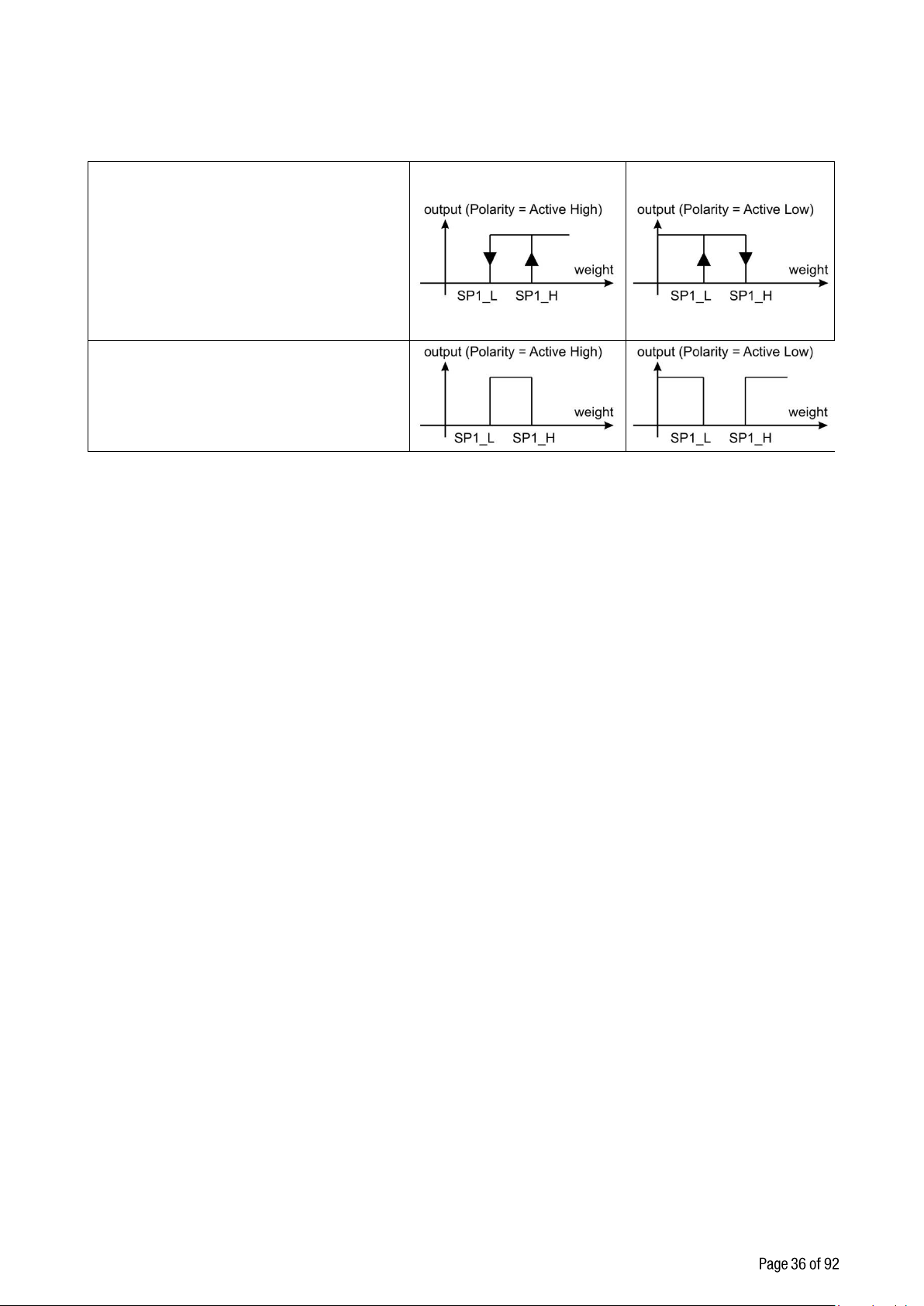
5.5.2 Digital Output Functions [70-]
Threshold Output :
2 set point values are entered. SP1
is the point that the output goes
active when the weight increased
from SP1_H. SP1_L is the point that
the output drops to passive state
when the weight decreased to
SP1_L.
Inverse function is available.
Window Output:
2 set point values are entered. The
output is active when the weight is
between SP1_L and SP1_H. Inverse
function is available.
FT-10 Smart Process Indicator, Technical Manual, Rev. 1.0, January 2014
In this block, the digital outputs are programmed for the functions indicated in the table below.
Table 5.1 - Digital output functions
[700 0] Output 1
Refer to Table 5.1 to select the output function.
0 : No function on output 1
1 : Threshold (Active High)
2 : Threshold (Active Low)
3 : Window (Active High)
4 : Window (Active Low)
5 : Fieldbus output
[701 0] Output 2
Refer to Table 5.1 to select the output function.
0 : No function on output 2
1 : Threshold (Active High)
2 : Threshold (Active Low)
3 : Window (Active High)
4 : Window (Active Low)
5 : Fieldbus output
[702 0] Output 3
Refer to Table 5.1 to select the output function.
0 : No function on output 3
1 : Threshold (Active High)
2 : Threshold (Active Low)
3 : Window (Active High)
4 : Window (Active Low)
5 : Fieldbus output
[703 0] Output 4
Refer to Table 5.1 to select the output function.
0 : No function on output 4
1 : Threshold (Active High)
2 : Threshold (Active Low)
3 : Window (Active High)
4 : Window (Active Low)
5 : Fieldbus output
Page 38

[704 0] Output 5 (only FT-10, FT-10 MB, FT-10 PB, FT-10 PN, FT -10 EN and FT-10 CO)
Refer to Table 5.1 to select the output function.
0 : No function on output 4
1 : Threshold (Active High)
2 : Threshold (Active Low)
3 : Window (Active High)
4 : Window (Active Low)
5 : Fieldbus output
5.5.3 Metrological Data Block [8--]
The parameters about Metrologic Registry are being entered in this section.
[80-] Legal Metrologic Records
[800] Counter
This counter increases by 1 automatically after entering the programming mode with calibration DIP
switch. This counter cannot be changed manually.
FT-10 Smart Process Indicator, Technical Manual, Rev. 1.0, January 2014
Page 39

5.5.4 Diagnostics [9--]
The operations about checking and testing FT-10 can be made here.
[90-] Tests
[900 ] Key Pad testing
In this step every keys ASCII code will be shown on the display as you press the related key. By this
way you can test if all the keys are functional or not. Pressing < > key will take you to the next
parameter.
[901 ] RS 232C Serial Interface testing
The characters in the alphabet will sequentially be transferred from RS 232C serial interface port by
pressing < Zero > key one after another. Received numerical data is seen on display.
[902 ] RS 485 Serial Interface testing
The characters in the alphabet will sequentially be transferred from RS 485 serial interface port by
pressing < Zero > key one after another. Received numerical data is seen on display.
[903 ] Parallel Inputs
[ı X Y]
To perform parallel input test, enter the number of parallel input to Y digits via < Zero > key.
X shows the logical condition of that input.
[904 ] Parallel Outputs
[o X Y]
To perform parallel output test, enter the number of parallel output to Y digits via < Zero > key.
Change the logical condition of that output via < Tare > key and X shows the logical condition of that
output.
[905 ] mV Indication
As you press < Enter > key the output voltage of the load cell will be shown on the display. This
uncalibrated value is only for test / service purposes.
[99-] Printing Parameter Values
[990] Print All Parameters
By pressing < Enter > key the whole parameters can be printed.
[991] Load Default
Press < Enter > key. [ Ld dEf ] message appears on the display. Press < Tare > key for loading
default parameter values or press < F > key to go [ 9- ] sub block.
The scale build parameters and calibration is not changed.
FT-10 Smart Process Indicator, Technical Manual, Rev. 1.0, January 2014
Page 40
6. SERIAL DATA OUTPUTS
Status
Indicated
Tare
STX
STA
STB
STC
D5
D4
D3
D2
D1
D0
D5
D4
D3
D2
D1
D0
CR
LF
CHK
Definition Table for Status A ( STA )
Bits 0, 1 and 2
Bits 3 and 4
Bit 5
Bit 6
Bit 7
0 1 2
Decimal point
3 4 Increment size
Always 1
Always 1
X
0 0 0
XXXXOO
1 0 X 1 1 0 0 XXXXXO
0 1 X 2 0 1 0 XXXXXX
1 1 X 5 1 1 0 XXXXX.X
0 0 1 XXXX.XX
1 0 1 XXX.XXX
0 1 1 XX.XXXX
1 1 1 X.XXXXX
Definition Table for Status B ( STB )
Bit 0
0 = Gross
1 = Net
Bit 1
0 = Weight positive
1 = Weight negative
Bit 2
0 = No Error
1 = Error
Bit 3
0 = Stable
1 = Unstable
Bit 4
Always = 1
Bit 5
Always = 1
Bit 6
0 = Not power on zeroed
1 = Zeroed with power on zero
Bit 7
x Definition Table for Status C ( STC )
Bit 0
Always 0
Bit 1
Always 0
Bit 2
Always 0
Bit 3
Always 0
Bit 4
Always 1
Bit 5
Always 1
Bit 6
Always 0
Bit 7
x
FT-10 indicator family has different kind of serial interfaces like RS 232, RS 485 and Ethernet etc. In this
section, you will find the data structure of different type of the data outputs via these serial ports except field
bus interfaces. You will find detailed information on field bus interfacing in the related sections.
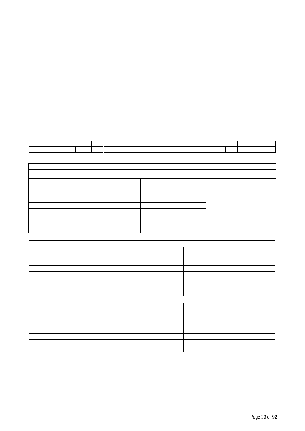
6.1 Continuous Data Output
Continuous data output of the instrument is transmitted in the following data structure. The serial ports of
FT-10 are suitable for bi-directional communication. If you transmit ASCII codes of P(print), Z(zero), T(tare)
or C(clear) letters to the serial port of FT-10; the indicator will act like the related keys are pressed.
CR (Carriage return) and LF (Line feed) codes can be enabled or disabled from response but they must be
sent to end of ASCII command.
CHK (Checksum) can be enabled or disabled from both command and response and only continuous data
output can be programmed for more than one interface.
The data format of continuous data output is;
The including of the status bytes STA, STB and STC are:
CHK (Checksum) = 0 – ( STX STATUS A ..... LF )
Error Messages: UNDER, OVER, A.OUT, L-VOLT, H-VOLT, are represented in Indicated data fields.
Note: The weight data is represented with right aligned and the error messages are represented with left
aligned.
Note: The continuous data is started to send after 20 seconds after power-on. This property helps to
connect IndFace1X on RS 485 bus.
FT-10 Smart Process Indicator, Technical Manual, Rev. 1.0, January 2014
Page 41
6.2 Fast Continuous Data Output
Multi Line-1 Format
Multi Line-2 Format
CN GROSS
TARE NET
M
S
D
L
S
D
SP M
S
D
L
S
D
SP M
S
D
L
S
D
SP M
S
D
L
S
D
LF C
R
9 3 13 3 13 3 13
1
1
Fast continuous “indicated weight” data output can be used only for the instruments which can communicate
fast. The output rate is related with the baud rate. Use higher baud rate for faster data rate. Received ASCII
codes of P(print), Z(zero), T(tare) or C(clear) letters, the indicator will act like the related keys are pressed.
CR and LF can be enabled in the related parameter.
The data format of the fast continuous data output is;
[STX][STATUS][SIGN][WEIGHT VALUE][CR][LF]
Examples :
S+000123.4 (weight is stable and 123.4)
D+000123.4 (weight is dynamic and 123.4)
+ (Over load)
- (Under load)
O (ADC out error)
6.3 Print Mode
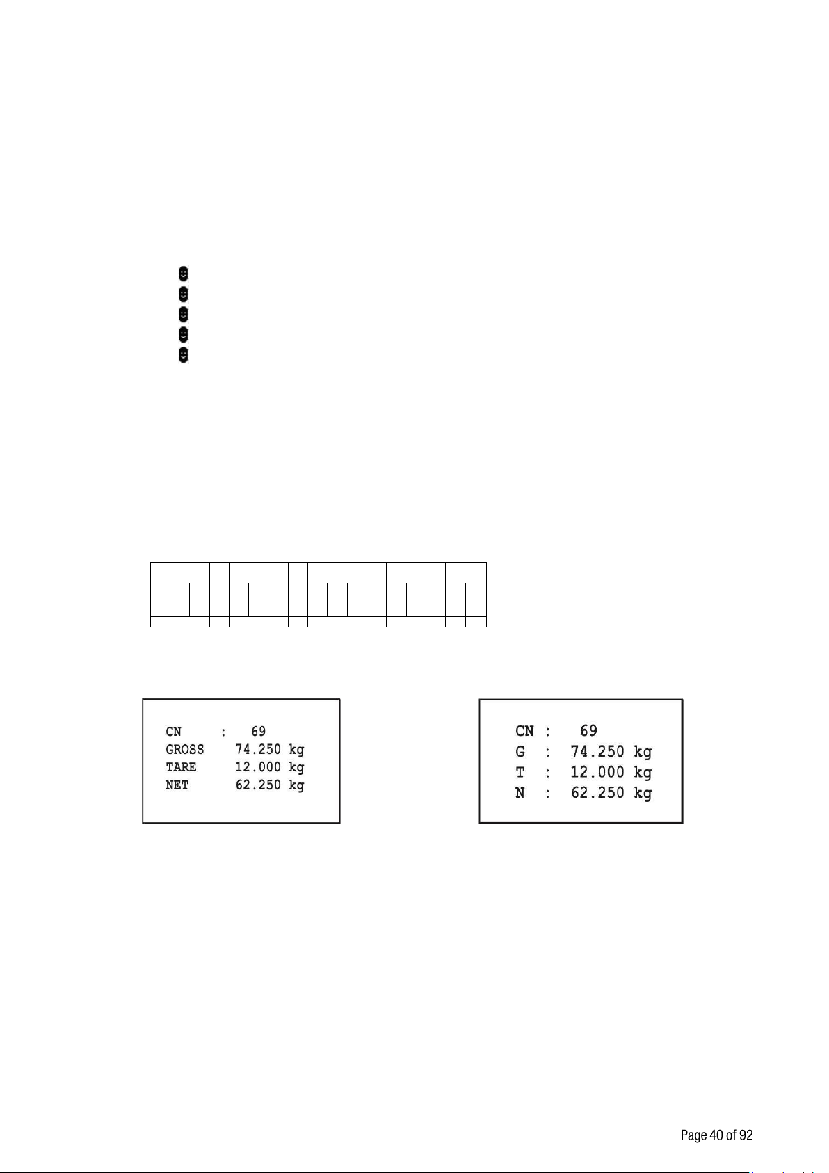
The format of the data output in Print mode can be selected in 3 different type forms in the parameter group
[ 04- ] . Only continuous format is available in more than one interface.
Single Line
You can send the data in single line like below by pressing < Enter > key.
CN: 21 G: 3.000kg T: 1.000kg N: 2.000kg
Multi Line
You can send the data in multiple lines as seen in the label given below by pressing < Enter > key. The data
output structure can be programmed with printer parameters.
6.4 BSI Data Structure
All new generation FLINTEC instruments launched on the market support the standardized command set
BSI data form, depending on the functionality of the instrument. This easy data format gives the reliable and
speedy interface advantages with communicating PLC or PC for process control or transactional
applications. You can expand your system with additional scales from FLINTEC without having to change
your application program base.
FT-10 Smart Process Indicator, Technical Manual, Rev. 1.0, January 2014
Page 42

General Rules:
1.
Commands are only in CAPITAL.
2.
CHK (2 ASCII char) can be enabled or disabled from both command and response.
3.
Weight data is 8-byte with dot and non-significant zeros on the left.
4.
Address (2 ASCII char) will be located in the structure, if not 00.
A
Read all weight data immediately
B
Read Gross weight value immediately
C
Clear the tare memory
G
Read voltage value of DC power supply
I
Read current weight (indicated) value immediately
P
Print: Read the current stable weight value
Q
Load set points
R
Read set points
S
Read Status
T
Tare
U
Read digital inputs
V
Read digital outputs
W
Set/Reset digital outputs
X
Read current weight value in increased resolution immediately
Z
Zero
A
Ack, the command is operated successfully
D
Dynamic, unstable weight
E
Errors except of H, L, O, +, −.
H
High voltage detected
I
The weight is in range
L
Low voltage detected
N
Nack, the command couldn’t be operated
O
ADC out
S
Stable weight
X
Syntax error ( not recognized the received command )
+
Overload
−
Underload
Command format:
A general description of the command is the following:
[ADR][COMMAND][CHK][CR][LF]
Response format with weight / force :
A general description of the response is the following:
[ADR][COMMAND][STATUS][SIGN][WEIGHT/FORCE][CHK][CR][LF]
Response format without weight / force
[ADR][COMMAND][STATUS][CHK][CR][LF]
Command Table:
Status Table:
Note: CHK, CR and LF will not be shown in below data format descriptions in this section.
FT-10 Smart Process Indicator, Technical Manual, Rev. 1.0, January 2014
Page 43
Commands and Responses:
A
Read all weight data
B
Read Gross weight
C
Clear the tare memory
G
Read voltage value of DC power supply
I
Read indicated weight
Command : [ADR][A]
Response : [ADR][A][STATUS][SIGN][NET W][SIGN][TARE W][SIGN][GROSS W]
Example :
Command : 01A
Response : 01AS+000123.4+000111.1+000234.5
01AD+000123.4+000111.1+000234.5
01AO ( ADC out error )
Comments :
The response is net, tare and gross weight values or error status.
All weight data is transmitted immediately after receiving the command.
Command : [ADR][B]
Response : [ADR][B][STATUS][SIGN][WEIGHT VALUE]
Example :
Command : 01B
Response : 01BS+000123.4 (gross weight is stable and 123.4)
01BD+000123.4 (gross weight is dynamic and 123.4)
01B− (under load)
Comments :
The response is the gross weight value (stable or dynamic) or error status.
Gross weight data is transmitted immediately after receiving command.
Command : [ADR][C]
Response : [ADR][C][A] (Cleared and the scale is in gross mode)
Comments :
The response status is always Ack in weighing or force mode.
Command : [ADR][G]
Response : [ADR][G][STATUS][VOLTAGE VALUE]
Example :
Command : 01G
Response : 01GA234 (Power supply is 23.4 VDC)
01GA150 (Power supply is 15.0 VDC)
01GA090 (Power supply is 9.0 VDC)
Comments :
Voltage value is 3 byte and sends with 0.1 V increment.
Command : [ADR][I]
Response : [ADR][I][STATUS][SIGN][WEIGHT VALUE]
Example :
Command : 01I
Response : 01IS+000123.4 (weight is stable and 123.4)
01ID+000123.4 (weight is dynamic and 123.4)
01I+ (overload)
Comments :
Indicated weight value (stable or dynamic) is transmitted immediately.
The weight value may be in gross or net.
FT-10 Smart Process Indicator, Technical Manual, Rev. 1.0, January 2014
Page 44

P
Print :Read the stable weight
Q
Load set points
R
Read set points
S
Read Status
T
Tare
Command : [ADR][P]
Response : [ADR][P][STATUS][SIGN][WEIGHT VALUE]
Example :
Command : 01P
Response : 01PS+000123.4 (weight is stable and 123.4) or
01PN (could not print)
Comments :
Checks status and it must be stable. Else Nack status is send.
Status can be Stable or Nack.
Command : [ADR][Q][SP No][SP Type][SIGN][SP VALUE]
Response : [ADR][Q][STATUS]
Example :
Command : 01Q01L+000123.4
Response : 01QA (123.4 loaded to SP1_L)
01QN (Could not loaded)
01QX (Decimal point of SP VALUE is mismatch)
Comments :
SP Number is 2 byte ASCII char. Use 01 for SP1, 02 for SP2 and 03 for SP3.
SP Type is 1 byte ASCII char. Use ‘L’ for SPx_L and use ‘H’ for SPx_H.
SP VALUE data is 8-byte ASCII char with dot and non-significant zeros on the left.
Command : [ADR][R][SP No][SP Type]
Response : [ADR][R][STATUS][SIGN][SP VALUE]
Example :
Command : 01R01L
Response : 01RA+000123.4 (SP1_L is 123.4)
01RN (Could not loaded)
Comments :
SP No is 2 byte ASCII char. Use 01 for SP1, 02 for SP2 and 03 for SP3.
SP Type is 1 byte ASCII char. Use ‘L’ for SPx_L and use ‘H’ for SPx_H.
SP VALUE data is 8-byte ASCII char with dot and non-significant zeros on the left.
Command : [ADR][S]
Response : [ADR][S][STATUS-1][STATUS-2][STATUS-3]
Example :
Command : 01S
Response : 01SSGI (Stable, Gross, In Range)
01SDGL (Dynamic, Gross, Low voltage error)
Comments :
The response includes 3 status information.
STATUS-1 can be Stable or Dynamic.
STATUS-2 can be Gross or Net.
STATUS-3 can be ‘In range’, ‘Out of range’, ‘+ Over’, ‘- Under’, ‘Low voltage’, ‘High voltage’ or ‘Errors’.
Command : [ADR][T]
Response : [ADR][T][A] (Taring is done successfully and scale is in net)
[ADR][T][N] (Taring could not executed)
[ADR][T][X] (Taring is disabled)
Comments :
The tare value is overwritten by the new tare weight value.
Status must be stable in 2 seconds time out delay. If so, Ack is send.
If it can not be stable in time out delay, Nack is send.
FT-10 Smart Process Indicator, Technical Manual, Rev. 1.0, January 2014
Page 45
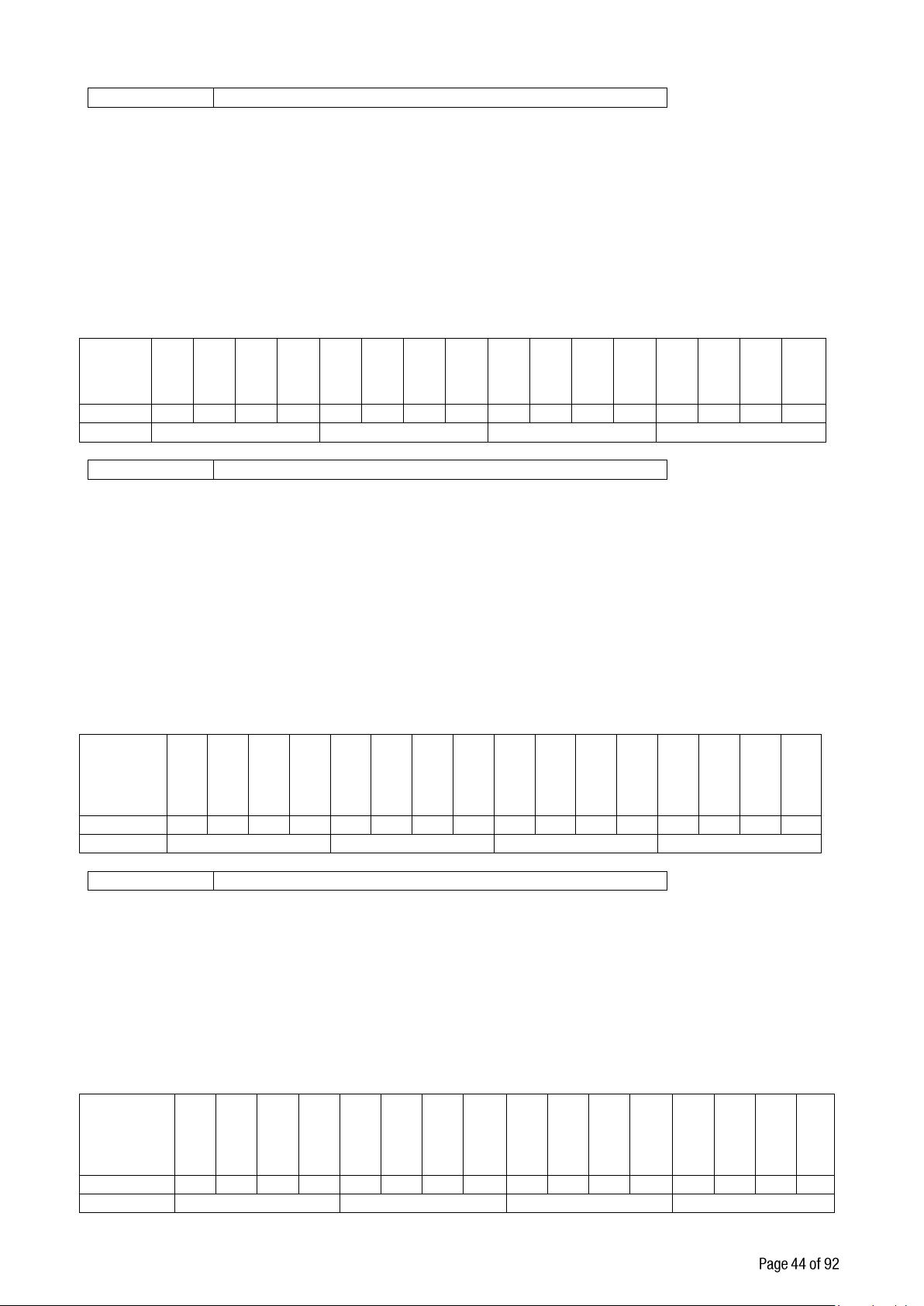
U
Read digital inputs
V
Read digital outputs
W
Set/Reset digital outputs
INPUT
S
IN-16
IN-15
IN-14
IN-13
IN-12
IN-11
IN-10
IN-9
IN-8
IN-7
IN-6
IN-5
IN-4
IN-3
IN-2
IN-1
Bit wise
0 1 0 0 0 0 1 0 1 0 0 1 0 1 1 0 ASCII
4 2 9
6
OUTPUT
S
OUT-16
OUT-15
OUT-14
OUT-13
OUT-12
OUT-11
OUT-10
OUT-9
OUT-8
OUT-7
OUT-6
OUT-5
OUT-4
OUT-3
OUT-2
OUT-1
Bit wise
0 1 0 0 0 0 1 0 1 0 0 1 0 1 1 0 ASCII
4 2 9
6
OUTPUTS
OUT-16
OUT-15
OUT-14
OUT-13
OUT-12
OUT-11
OUT-10
OUT-9
OUT-8
OUT-7
OUT-6
OUT-5
OUT-4
OUT-3
OUT-2
OUT-1
Bit wise
0 1 0 0 0 0 1 0 1 0 0 1 0 1 1 0 ASCII
4 2 9
6
Command : [ADR][U]
Response : [ADR][U][STATUS][Inputs]
Example :
Command : 01U
Response : 01UA03 (Input 2 and Input 1 are active)
01UA4296 (Input 15,10,8,5,3,2 are active)
01UAFF (All 8 inputs are active)
01UN (Could not read inputs)
Comments :
Data length change according to number of digital inputs.
Inputs are implemented to ASCII char of 4-bit. ‘1111’ inputs are implemented to char ‘F’.
Command : [ADR][V]
Response : [ADR][V][STATUS][Outputs]
Example :
Command : 01V
Response : 01VA03 (Output 2 and Output 1 are active)
01VA4296 (Output 15,10,8,5,3,2 are active)
01VAFF (All 8 outputs are active)
01VN (Could not read outputs)
Comments :
Data length change according to number of digital outputs.
Outputs are implemented to ASCII char of 4-bit. ‘1111’ is implemented to char ‘F’.
Command : [ADR][W][Outputs]
Response : [ADR][W][STATUS]
Example :
Command : 01W4296
Response : 01WA (Outputs 15,10,8,5,3,2 are activated)
01WN (Outputs could not be activated)
Comments :
Data length change according to number of digital outputs.
Outputs are implemented to ASCII char of 4-bit. ‘1111’ outputs are implemented to char F’.
FT-10 Smart Process Indicator, Technical Manual, Rev. 1.0, January 2014
Page 46

X
Read weight value in increased resolution
Z
Zero
Command : [ADR][X]
Response : [ADR][X][STATUS][SIGN][WEIGHT VALUE]
Example :
Command : 01X
Response : 01XS+00123.41 (weight is stable and 123.41) or
01XD+00123.41 (weight is dynamic and 123.41) or
01XE (Error)
Comments :
The response includes weight data with divided the increment to 10.
Command : [ADR][Z]
Response : [ADR][Z][A] (Zeroed)
[ADR][Z][N] (Zeroing could not be operated)
[ADR][Z][X] (Zeroing is disabled)
Comments :
Zero command can not work in net weighing.
Weight must be in zeroing range for all operating modes.
Status must be stable in 2 seconds time out delay. If so, Ack is send.
If it can not be stable in time out delay, Nack is send.
Checksum Calculation:
CHK is transmitted as two ASCII characters calculated with the Checksum formulation.
Checksum = 0 – (SUM of all response data before CHK)
Example: Read stable current weight data.
BSI Examples: (CHK is enabled and instrument address is 01)
Command: 01P[CHK][CR][LF]
Checksum = 0 − (0x30 + 0x31 + 0x50)
= 0 − 0XB1
= 0x4F
= Char ‘4’ and ‘F’
Response: 01PS+000123.4[CHK][CR][LF]
Checksum = 0 − (0x30 + 0x31 + 0x50 + 0x53 + 0x2B + 0x30 + 0x30 + 0x30 + 0x31+ 0x32 + 0x33 + 0x2E +
0x34)
= 0 − 0x02B7
= 0x49
= Char ‘4’ and Char ‘9’
FT-10 Smart Process Indicator, Technical Manual, Rev. 1.0, January 2014
Page 47

7. ANALOGUE ( ONLY FT-10 AN )
Under Zero
When the gross indication drops below zero, the analog output reduces
the analog output to 0mA or - 4 V to indicate error on the analog output.
Normal Range
The analog output will reflect the gross value to the programmed analog
output 4 – 20 mA, 0 – 20 mA, 0 – 5 V or 0 – 10 V.
Over High Limit
When the gross value exceeds the high limit, the analog signal increase to
approximately 24 mA or 11 V and remains there until the weight display is
no longer blanked or the analog signal returns to within range.
Condition ( On Display )
4-20 mA
output
0-20 mA
output
0 – 5 V
output
0 – 10 V
output
The weight is more than the range ( Over )
24 mA
24 mA
5.5 V
11 V
The weight is under the zero range ( Under )
0 mA
0 mA
-4.0 V
-4.0 V
Error [ Err XX ]
24 mA
24 mA
5.5 V
11 V
ADC is out of operating range [ Adc Out ]
24 mA
24 mA
5.5 V
11 V
FT-10 AN is programmable to 4 – 20 mA, 0 – 20 mA, 0 – 5 V or 0 – 10 V analogue output types. Analog
output is automatically adjusted to the weighing range after the calibration. The mid value of the analog
output is set to zero load at bipolar usage
The analogue output is related with the gross load of the scale. The analog output signal operates as
described next.
The following table indicates the analog output value when the gross indication is out of the range and if
there is any error indication on the display.
The error data indicated above can be used to follow the errors at PLC.
[4--] Analogue Output Block
The calibration of the analogue output is performed in this sub-block.
[40-] Signal Selection
[400 0] Analogue Output Mode
0 : 4 – 20 mA
1 : 0 – 20 mA
2 : 0 – 5 VDC
3 : 0 – 10 VDC
[401] Set Analogue Output to calibration range
Press < Enter > key. [ Ld dEf ] message appears on the display. Press < Tare > key for loading
default values or press < F > key to go next sub block.
[41-] Zero Adjustment
[410] Coarse Zero Adjustment
The coarse zero adjustment is being performed by pressing < Zero > key one after another to
increase the analogue signal level or < Tare > key to decrease the analogue signal level.
[411] Fine Zero Adjustment
The fine zero adjustment is being performed by pressing < Zero > key continuously one after
another to increase the analogue signal level or < Tare > key to decrease the analogue signal level.
FT-10 Smart Process Indicator, Technical Manual, Rev. 1.0, January 2014
Page 48

[42-] Span Adjustment
[420] Coarse Span Adjustment
Coarse span adjustment is being performed by pressing < Zero > key continuously one after
another to increase the analogue signal level or < Tare > key to decrease the analogue signal level
by taking the full capacity value as reference without placing any weight.
[421] Fine Span Adjustment
Fine span adjustment is being performed by pressing < Zero > key one after another to increase
the analogue signal level or < Tare > key to decrease the analogue signal level by taking the full
capacity value as reference without placing any weight.
FT-10 Smart Process Indicator, Technical Manual, Rev. 1.0, January 2014
Page 49
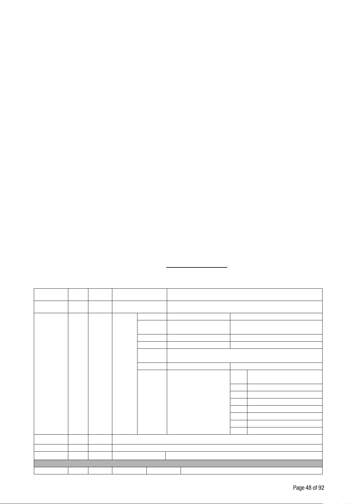
8. MODBUS RTU ( ONLY FT-10 MB )
Address
R/W
Word
Command
Definition
40001
R 2 Indicated weight
( Net if the indication is in Net )
40003
R 1 Status
D0
0 – System Ready
1 – System Busy
D1
0 – Error ( D13-D15
)
1 – Data ok
D2
0 – Weight Stable
1 – Weight unstable
D3
0 – Gross Mode
1 – Net mode
D4 –
D11
Not used
D12
0 – Out of zero range
1 – Weight is in zero range
D13
D14
D15
Error Code
De
c
Description
0
No Errors
1
ADC out of range
2
ADC over range
3
ADC under range
4
System error
5
In programming mode
6
Low/High voltage det.
40004
R 2 Tare weight
40006
R 2 Gross weight
40008
R 1 Status
Motion, Net mode, Data ok, (image of register 40003)
40009
R/W
1
Control
Dec
Description
FT-10 MB indicator has a Modbus RTU interface over RS 485 / RS 232C serial port. This interface can be
programmable to High-Low or Low-High for different type of PLC’s. You can find below the difference of
these data formats and some companies using these formats. Two types are available as;
8.1 Modbus RTU Data Structure
After programming RS 485 / RS 232C serial port for Modbus RTU, it can be used as a Modbus RTU slave on
Modbus RTU network. The Modbus slave address is defined in the RS-485 address (Page 25). Functions
code ‘0x03’ (Read Holding Registers) and ‘0x10’ (Preset Multiple Registers) are supported.
Modbus RTU High-Low: In two word registers, the data is stored to the registers in big-endian format. Least
significant word is stored to the highest register address; and most significant word is stored to the lowest
register address.
Modbus RTU Low-High: In two word registers, the data is stored to the registers in little-endian format.
Least significant word is stored to the lowest register address; and most significant word is stored to the
highest register address.
[00-] RS 232C Serial Port
This sub-block includes the parameters about the 1st serial interface of FT-10.
[000 3 ] Data Format
4 : Modbus RTU High-Low
5 : Modbus RTU Low-High
Set the RS 485 / RS 232C Data Format : Modbus RTU High-Low or Modbus RTU Low-High
RS-485 Data Length & Parity : 8 none 1,
RS-485 Address : 01 to 31
Make the RS-485 / RS 232C parameter settings as defined on (Page 24).
Please find Modbus information in the web site of http://www.modbus.org
Modbus RTU Command Table;
FT-10 Smart Process Indicator, Technical Manual, Rev. 1.0, January 2014
Page 50
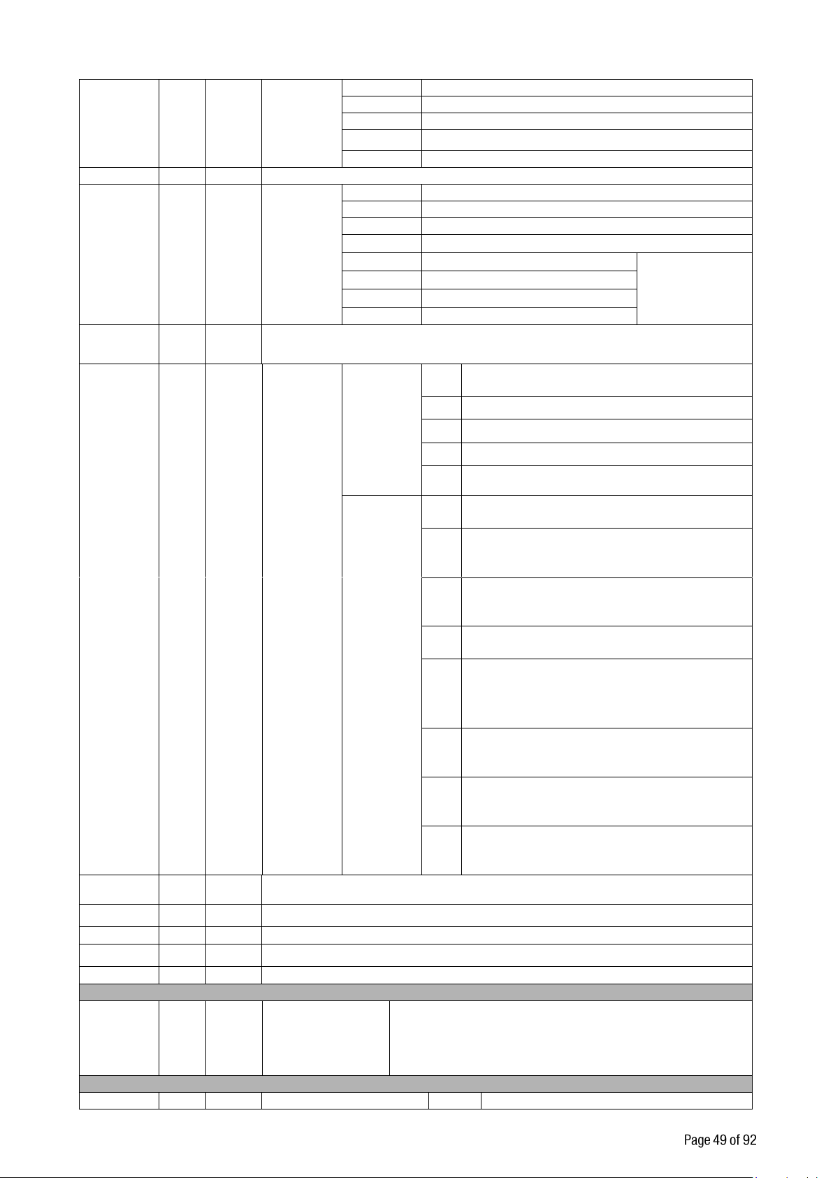
0
None
1
Zero
2
Tare
3
Clear
4
Print
40010
R/W
20
Not used
40030
R/W
1
Calibratio
n
Dec
Description
0
None
188
Adjust Zero Calibration
220
Adjust Span Calibration
( 1 )
236
Total Load Cell Capacity
( 1 )
eCal
Coefficients
250
Average mV/V
( 1 )
171
Dead Load
( 1 )
23205
Save the coefficients of eCal
40031
R/W
2
Span Calibration Value / LC capacity / mV value / Dead load value
40033
R
1
Calibratio
n Status
D0 .. D7
Calibratio
n Process
Status
De
c
Description
1
Ready for calibration
3
Zero calibration in process …
4
Span calibration in process …
9
Error (Refer to D8 ... D15 )
D8 .. D15
Calibratio
n Errors
1
Calibration Timeout
- Restart calibration
2
ADC Error
- Re-energize the instrument
- If seen again, change the board.
3
Instrument can not be calibrating
- Check load cell cable
- Re-energize the instrument
34
Instrument can not be calibrating
- Load cell signal is very low or too high
35
Calibration Error
- Calibration loading is not enough
- Check test weight loading
- Check load cell connections
36
Calibration load value entry Error
- Test weight is too small. Increase the test
weight
37
Scale unstable
- Wait until scale become stable
- Check grounding wiring
38
The Calibration DIP switch is not ON
position.
- Check the calibration DIP switch.
40034
R/W
37
Not used
40071
R 1 Indicated weight
40072
R 1 Status
40073
R 1 Tare weight
40074
R 1 Gross weight
40100
R
1
Voltage of
Power Supply
Voltage of power supply is indicated with 0.1 V
increment.
For example: 23.4 VDC is indicated as integer 234
value.
40200
R 1 Status of Inputs
D0
Input-1
FT-10 Smart Process Indicator, Technical Manual, Rev. 1.0, January 2014
Page 51
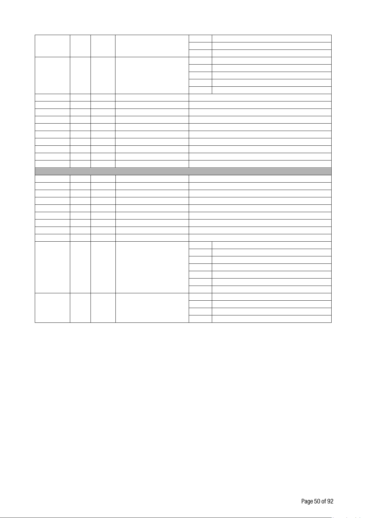
D1
Input-2
D2
Input-3
D3
Input-4
40201
R/W
1
Status of Outputs
D0
Output-1
D1
Output-2
D2
Output-3
D3
Output-4
D4
Output-5
40202
R/W
2
Setpoint 1 Low
( 2 )
40204
R/W
2
Setpoint 1 High
40206
R/W
2
Setpoint 2 Low
( 2 )
40208
R/W
2
Setpoint 2 High
40210
R/W
2
Setpoint 3 Low
( 2 )
40212
R/W
2
Setpoint 3 High
40214
R/W
2
Setpoint 4 Low
( 2 )
40216
R/W
2
Setpoint 4 High
40218
R/W
2
Setpoint 5 Low
( 2 )
40220
R/W
2
Setpoint 5 High
42000
R/W
1
Filter
Refer to parameter [120] on page 29
42001
R/W
1
Power On Zero
Refer to parameter [202] on page 30
42002
R/W
1
Zeroing Range
Refer to parameter [203] on page 30
42003
R/W
1
Auto Zero Tracking
Refer to parameter [204] on page 30
42004
R/W
1
Tare
Refer to parameter [205] on page 30
42005
R/W
1
Motion Detector
Refer to parameter [206] on page 30
42006
R/W
1
Stability Period
Refer to parameter [207] on page 30
42007
R/W
1
Operation mode
Refer to parameter [210] on page 31
42008
R/W
2
Capacity
Refer to parameter [212] on page 31
42010
R/W
1
Decimal point
Dec
Description
0
XXXXOO
1
XXXXXO
2
XXXXXX
3
XXXXX.X
4
XXXX.XX
5
XXX.XXX
42011
R/W
1
Increment
Dec
Description
1
X 1 2 X 2 3 X 5
(1) Write this command after writing values to 40031-32 addresses.
(2) Only set point low addresses are used if the set point is programmed as standard.
Programming steps of frequent used ……
Reading a weight value:
1. Read 40003,
2. Check D0=0 and D1=1,
3. If yes, read a weight value ( gross, net or tare),
4. If D0=1, check D0 until system ready,
5. If D1=0, check the error code.
Zero Calibration procedure:
1. Check the low byte of 40033. it should be decimal '1' to start adjustment.
2. Load the decimal '188' to 40030 to start Zero calibration.
3. Check the low byte of 40033. it is decimal '3' during zero calibration process.
4. The low byte of 40033 changes to decimal '1' at the end of the Zero calibration.
5. If the low byte of 40033 is '9', check the high byte of 40033 to understand the calibration error.
Span Calibration procedure:
1. Check the low byte of 40033. it should be decimal '1' to start adjustment.
2. First load the span value to 40031-32 and then load the decimal '220' to 40030 to start Span
calibration.
3. Check the low byte of 40033. it is decimal '4' during span calibration process.
FT-10 Smart Process Indicator, Technical Manual, Rev. 1.0, January 2014
Page 52
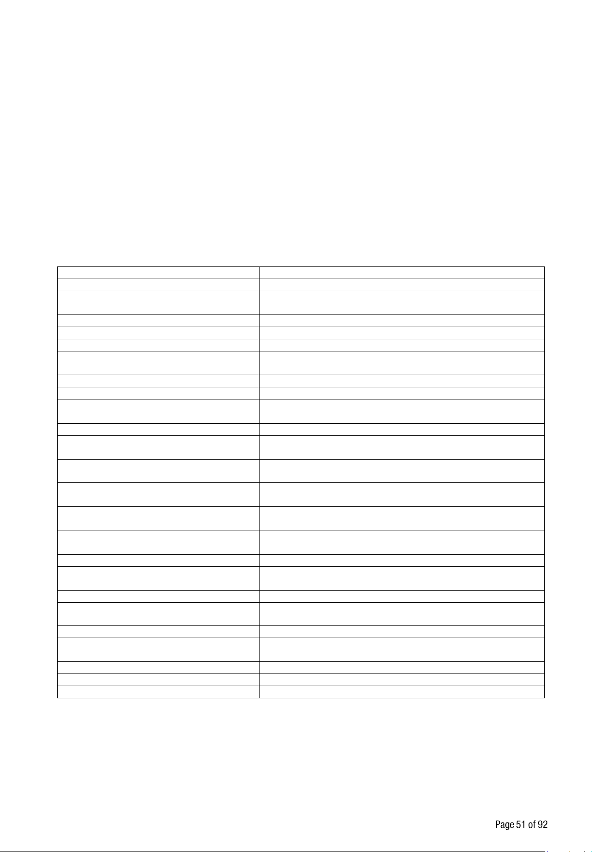
4. The low byte of 40033 changes to decimal '1' at the end of the Span calibration.
Description
Hex
Request weight data
01,03,00,00,00,02,C4,0B
Answer of request weight
(weight value is 100000 )
01,03,04,00,01,86,A0,38,4A
Request status data
01,03,00,02,00,01,25,CA
Taring
01,10,00,08,00,01,02,00,02,26,D9
Request tare data
01,03,00,03,00,02,34,0B
Answer of request tare
(tare value is 10000 )
01,03,04,00,00,27,10,E0,0F
Zero Command
01,10,00,08,00,01,02,00,01,66,D8
Request Calibration Status
01,03,00,20,00,01,85,C0
Answer of request Calibration Status
(Instrument is ready for calibration)
01,03,02,00,01,79,84
Zero Calibration
01,10,00,1D,00,01,02,00,BC,A4,6C
Span Calibration Command with Span
value 50000
01,10,00,1D,00,03,06,00,DC,00,00,C3,50,F7,F0
Total LC capacity Command with
Total LC capacity value 100000
01,10,00,1D,00,03,06,00,EC,00,01,86,A0,D4,E0
Average mV/V Command with
Average mV/V value 1.9999
01,10,00,1D,00,03,06,00,FA,00,00,4E,1F,DA,93
Dead load Command with Dead load
value 12345
01,10,00,1D,00,03,06,00,AB,00,00,30,39,87,25
Save the coefficients of eCal
Command
01,10,00,1D,00,01,02,5A,A5,5F,06
Read Voltage of Power Supply value
01,03,00,63,00,01,74,14
Answer of Voltage of Power Supply
(Voltage of Power Supply is 23,5 V)
01,03,02,00,EB,F8,0B
Read digital inputs
01,03,00,C7,00,01,35,F7
Answer of digital inputs
(Input-2 is active)
01,03,02,00,02,39,85
Read digital outputs
01,03,00,C8,00,01,05,F4
Answer of digital outputs
(Output-3 is Active)
01,03,02,00,04,B9,87
Read Setpoint-1 Low
01,03,00,C9,00,02,14,35
Answer of Setpoint-1 Low
01,03,04,00,00,03,E8,FA,8D
Load Set point 1 Low = 5000
01,10,00,C9,00,02,04,00,00,13,88,32,C3
5. If the low byte of 40033 is '9', check the high byte of 40033 to understand the calibration error.
EXPLANATION:
Attention: For hardware connection details, please refer to the related hardware descriptions in this manual.
Exception codes:
1: Function code is not supported.
2: Out of beginning and ending address range.
3: Invalid value entrance or wrong byte number.
4: Operation error.
Command Examples:
Performing Read and Write operations according (Modbus RTU High-Low) to hex system with the instrument
set to address “0x01”.
Below you will find some command samples;
FT-10 Smart Process Indicator, Technical Manual, Rev. 1.0, January 2014
Page 53
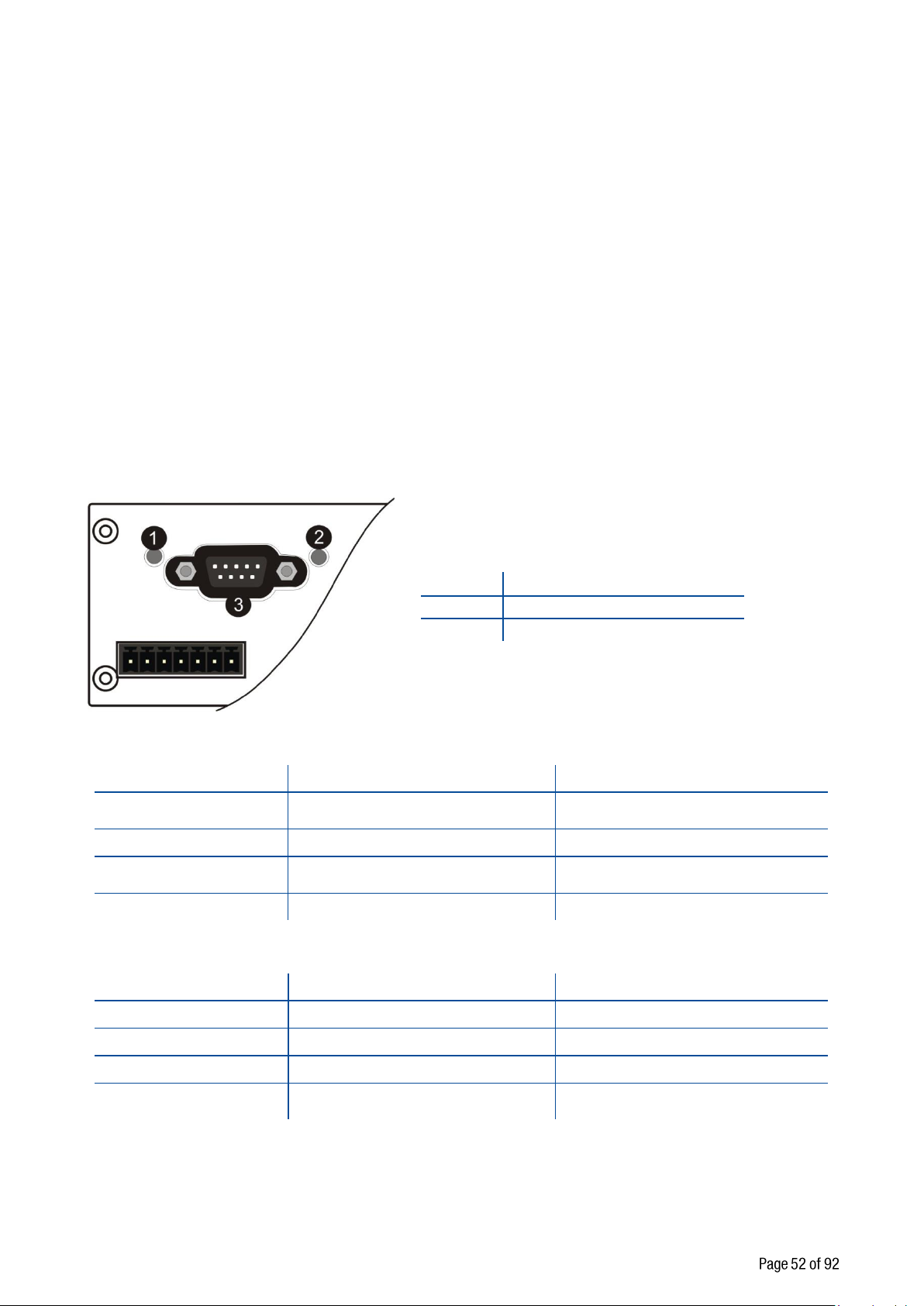
9. PROFIBUS ( ONLY FT-10 PB )
State
Indication
Comment
Off
Not power or not initialized
No power or profibus module is in
initialization state
Green
Initialized
Flashing Green
Initialized, diagnostic event(s)
present
Diagnostic is active
Red
Exception error
There is an exception error
State
Indication
Comment
Off
Not online /No power
Check power and cable
Green
On-line, data exchange
-
Flashing Green
On-line, clear
-
Flashing Red
(2 flash)
PROFIBUS configuration error
Check GSD file configuration.
1
OP Operation mode LED
2
ST Status LED
3
Profibus Connector
In Profibus DPV1 interface, baud rate is detected automatically. Supported baud rates are 9.6 kbps, 19.2
kbps, 45.45 kbps, 93.75 kbps, 187.5 kbps, 500 kbps, 1.5 Mbps, 3 Mbps, 6 Mbps and 12 Mbps. No ‘baud
rate’ instance exists.
After programming Profibus related parameters of the FT-10 PB indicator, you can communicate with the
instrument. GSD file is available in CD which is supplied together with the instrument.
[05-] Profibus
This sub-block includes the parameters related with the Profibus interfaces of FT-10 indicator.
[050 0 ] Data Format
0 : Signed 32 bit integer, no decimal point implied
1 : 32 bit float, decimal point implied
[051 000] Rack Address
The Profibus rack address of FT-10 will be entered via keypad between 1 to 126.
There are two LED’s near the Profibus connector which are ;
ST Status LED
OP Operation mode LED
FT-10 Smart Process Indicator, Technical Manual, Rev. 1.0, January 2014
Page 54
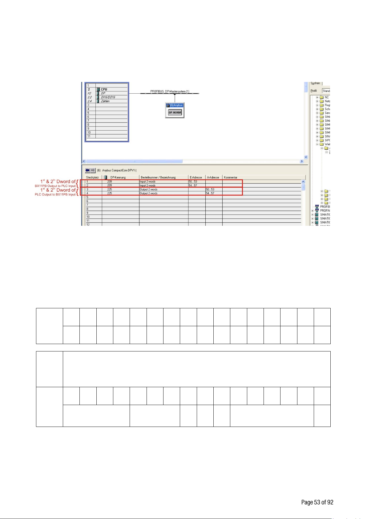
9.1 GSD Configuration
Dword
(Only
read)
D31
D30
D29
D28
D27
D26
D25
D24
D23
D22
D21
D20
D19
D18
D17
D16
D15
D14
D13
D12
D11
D10
D9
D8
D7
D6
D5
D4
D3
D2
D1
D0
1st
Dword
By default, Indicated weight value is represented.
To represent other weight or calibration status, refer to next Dword.
2nd
Dword
Out 5 Out 4 Out 3 Out 2 Out
1
In 4 In 3 In 2 In
1
Error codes of FT-10
PB
Not in use
Zero
range
Gros
s
Net
MD
Read command response
Cmd
Flag
Profibus data consists of 2 x Input 2 words and 2 x Output 2 words. GSD configuration for PLC
programmers is shown in Figure 9.1.
Figure 9.1 - GSD Configuration
9.2 Profibus DP Data Structure
FT-10 PB Output to PLC Input
Bitwise of a Dword:
FT-10 Smart Process Indicator, Technical Manual, Rev. 1.0, January 2014
Page 55
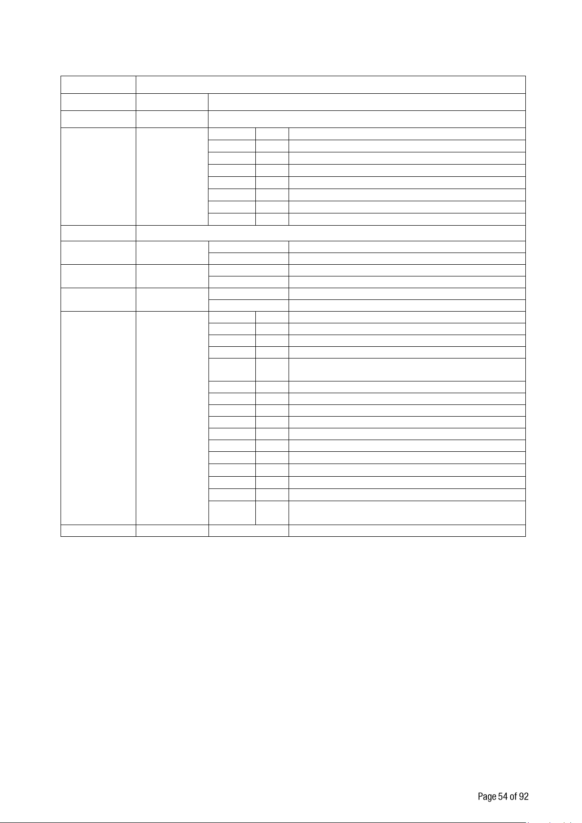
FT-10 PB Output to PLC Input 2nd Dword
Bit Number
2nd Dword Description
D31 … D24
Outputs
Output bit status ( Active = 1 )
D23 … D16
Inputs
Input bit status ( Active = 1 )
D15 … D12
Error Codes
of FT-10 PB
Bin
Dec
0000
0
No error found
0001
1
ADC out
0010
2
ADC over
0011
3
ADC under
0100
4
System Error
0101
5
In programming mode
0110
6
Low/High Voltage Error
D11 … D9
Not in use
D8
Zero Range
0
Weight is in zero range
1
Weight is out of zero range
D7
Indication
0
Gross
1
Net
D6
MD – Motion
Detection
0
Stable
1
Dynamic
D5 … D1
D5 … D1
Read
Command
Response
Read
Command
Response
(continuation
of previous
page)
00000
0
Indicated weight
00001
1
Gross weight
00010
2
Tare weight
00011
3
Calibration Status
00100
01110
4
14
Not used
01111
15
Set Point-1 Low
10000
16
Set Point-1 High
10001
17
Set Point-2 Low
10010
18
Set Point-2 High
10011
19
Set Point-3 Low
10100
20
Set Point-3 High
10101
21
Set Point-4 Low
10110
22
Set Point-4 High
10111
23
Set Point-5 Low
11000
24
Set Point-5 High
11111
31
Use the Expanded Command list ( Refer to Table
9.1 )
D0
CMD Flag
Toggles
The command is applied successfully
FT-10 Smart Process Indicator, Technical Manual, Rev. 1.0, January 2014
Page 56
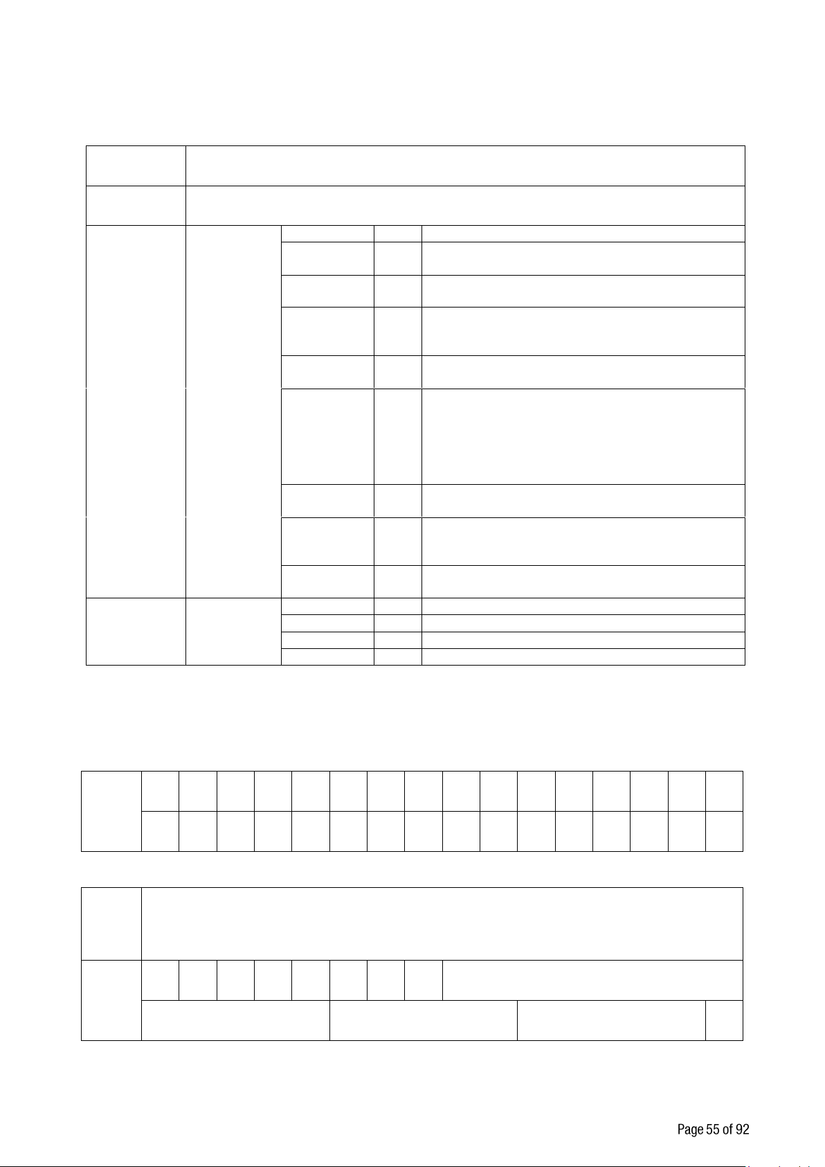
Calibration Status (always 32 bit integer)
Bit Number
1st Dword Description
D31 … D16
Not in use
D15 … D8
Calibration
Errors
Bin
Dec
Descriptions
0000 0001
1
Calibration Timeout
- Restart calibration
0000 0010
2
ADC Error
- Re-energize the instrument
0000 0011
3
Instrument can not be calibrating
- Check load cell cable
- Re-energize the instrument
0010 0010
34
Instrument can not be calibrating
- Load cell signal is very low or too high
0010 0011
35
Calibration Error
- Calibration loading is not enough
- Check test weight loading (Write test weight
value to 1
st
Dword of PLC Output to FT-10 PB
Input then restart the calibration)
- Check load cell connections
0010 0100
36
Calibration load value entry Error
- Test weight is too small. Increase the test weight
0010 0101
37
Scale unstable
- Wait until scale become stable
- Check grounding wiring
0010 0110
38
The Calibration DIP switch is not ON position.
- Check the calibration DIP switch.
D7 ... D0
Calibration
Process
Status
0000 0001
1
System ready for calibration
0000 0011
3
Zero calibration in process
0000 0100
4
Span calibration in process
0000 1001
9
Error ( Refer to Calibration Errors )
Dword
(R/W)
D31
D30
D29
D28
D27
D26
D25
D24
D23
D22
D21
D20
D19
D18
D17
D16
D15
D14
D13
D12
D11
D10
D9
D8
D7
D6
D5
D4
D3
D2
D1
D0
1st
Dword
Next Dword defines the usage of this Dword.
2nd
Dword
Out 5 Out 4 Out 3 Out 2 Out
1
Expanded Commands List
Not in use
Command List
Read Data Selection
New
CMD
1st Dword descriptions when read command is ‘Calibration Status’. Refer to 2nd Dword of PLC Output to FT10 PB Input
PLC Output to FT-10 PB Input
Bitwise of a Dword:
FT-10 Smart Process Indicator, Technical Manual, Rev. 1.0, January 2014
Table 9.1 – Calibration Status
Page 57
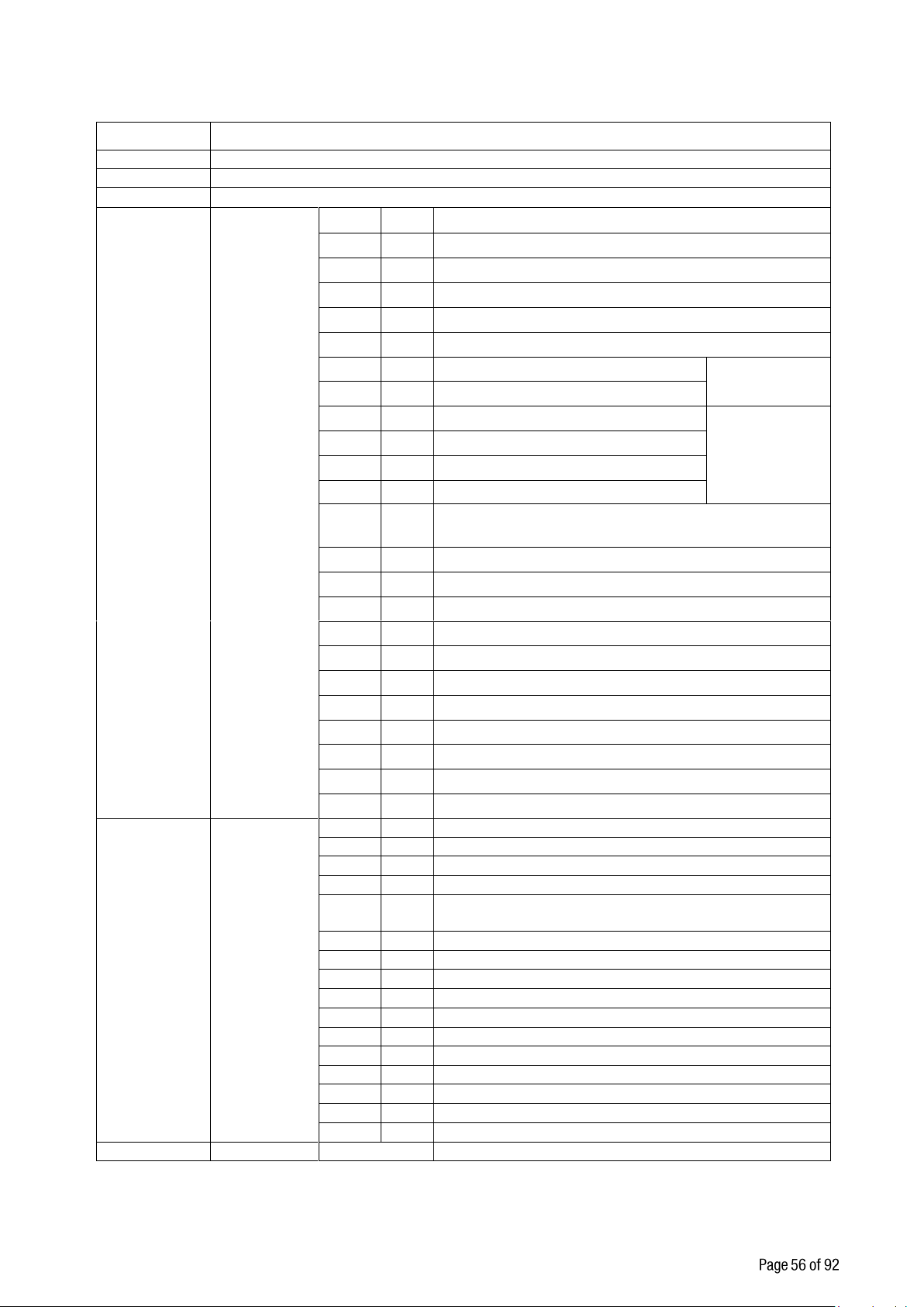
PLC Output to FT-10 PB Input 2nd Dword
Bit Number
2rd Dword descriptions
D31 … D24
Set / Reset digital outputs
D23 … D16
Expanded Commands List ( Refer to Table 9.1 )
D15 ... D11
Not in use
D10 … D6
D10 … D6
Command
List
(continuation
of previous
page)
Bin
Dec
Commands
00000
0
None command is activated
00001
1
Zero
00010
2
Tare
00011
3
Clear
00100
4
Print
00101
5
Adjust zero calibration
Calibration
00110
6
Adjust span calibration
(1)
00111
7
Total Load Cell Capacity
(1)
eCal
Coefficients
Refer to par.
[313]
01000
8
Average mV/V value
(1)
01001
9
Dead Load value
(1)
01010
10
Save the coefficients of eCal
01011
01110
11
14
Not used
01111
15
Set Point-1 Low
(1)
10000
16
Set Point-1 High
(1)
10001
17
Set Point-2 Low
(1)
10010
18
Set Point-2 High
(1)
10011
19
Set Point-3 Low
(1)
10100
20
Set Point-3 High
(1)
10101
21
Set Point-4 Low
(1)
10110
22
Set Point-4 High
(1)
10111
23
Set Point-5 Low
(1)
11000
24
Set Point-5 High
(1)
11111
31
Use the Expanded Command list ( Refer to Table 9.1 )
D5 ... D1
Read Data
Selection
00000
0
Indicated weight
00001
1
Gross weight
00010
2
Tare weight
00011
3
Calibration Status ( Refer to Table 9.1 )
00100
01110
4
14
Not used
01111
15
Set Point-1 Low
( 2 )
10000
16
Set Point-1 High
10001
17
Set Point-2 Low
( 2 )
10010
18
Set Point-2 High
10011
19
Set Point-3 Low
( 2 )
10100
20
Set Point-3 High
10101
21
Set Point-4 Low
( 2 )
10110
22
Set Point-4 High
10111
23
Set Point-5 Low
( 2 )
11000
24
Set Point-5 High
11111
31
Use the Expanded Command list ( Refer to Table 9.1 )
D0
New CMD
Toggle
Apply commands which are listed in this table
(1) Write this command after writing values to 1st Dword , then apply this command with New CMD
(2) Only set point low addresses are used if the set point is programmed as standard.
FT-10 Smart Process Indicator, Technical Manual, Rev. 1.0, January 2014
Page 58
Expanded Command List (always 32 bit integer)
Bit No
Description
D23…D16
Expanded
Commands
List
(continuation
of previous
page)
Bin
De
c
Commands
0000000
0
0
R
Voltage of
Power Supply
Indicated with 0.1 VDC
increment.
0000000
1
0011111
1
1
63
Not in use
0100000
0
64
RW
Filter
(1)
Refer to par. [120] on page
29
0100000
1
65
RW
Power On Zero
(1)
Refer to par. [202] on page
30
0100001
0
66
RW
Zeroing Range
(1)
Refer to par. [203] on page
30
0100001
1
67
RW
Auto Zero
Tracking
(1)
Refer to par. [204] on page
30
0100010
0
68
RW
Tare
(1)
Refer to par. [205] on page
30
0100010
1
69
RW
Motion Detector
(1)
Refer to par. [206] on page
30
0100011
0
70
RW
Stability Period
(1)
Refer to par. [207] on page
30
0100011
1
71
RW
Operation mode
(1)
Refer to par. [210] on page
31
0100100
0
72
RW
Capacity
(1)
Refer to par. [212] on page
31
0100100
1
73
RW
Decimal point
(1)
0
XXXXOO
1
XXXXXO
2
XXXXXX
3
XXXXX.X
4
XXXX.XX
5
XXX.XXX
0100101
0
74
RW
Increment
(1)
1
X1 2 X2 3 X5
The “D23 … D16” bits in 2
nd
Dword describes below.
(1) Write this command after writing values to 1st Dword then apply this command with New CMD
Programming steps of frequent used ……
Reading a weight value:
1. Check the D12…D15 bits of ‘FT-10 PB Output to PLC Input 2nd Dword’.
2. If there is not any error, read a weight value ( gross, net or tare),
Zero Calibration procedure:
1. Check the low byte of Calibration Status. it should be decimal '1' to start adjustment.
2. Write ‘Adjust Zero Calibration’ command and apply New CMD to start Zero calibration.
3. Check the low byte of Calibration Status. it is decimal '3' during zero calibration process.
4. The low byte of Calibration Status changes to decimal '1' at the end of the Zero calibration.
5. If the low byte of Calibration Status is '9', check the high byte of Calibration Status to understand the
calibration error.
Span Calibration procedure:
1. Check the low byte of Calibration Status. it should be decimal '1' to start adjustment.
2. Write ‘Adjust Span Calibration’ command after writing test weight values to 1st Dword, then apply this
command with New CMD to start Span calibration.
3. Check the low byte of Calibration Status. it is decimal '4' during span calibration process.
4. The low byte of Calibration Status changes to decimal '1' at the end of the Span calibration.
5. If the low byte of Calibration Status is '9', check the high byte of Calibration Status to understand the
FT-10 Smart Process Indicator, Technical Manual, Rev. 1.0, January 2014
calibration error.
Table 9.1 - Expanded Command List
Page 59
10. PROFINET ( ONLY FT-10 PN )
LED State
Description
Comment
Off
Not power or not initialized
No power or profinet module is in
initialization state
Green
Initialized
Green, 1 flash
Initialized, diagnostic event(s) present
Diagnostic is active
Red
Exception error
There is an exception error
Red, 1 flash
Configuration Error
Check GSDML configuration
Red, 2 flashes
IP Address Error
IP address not set
Red, 3 flashes
Station Name Error
Station name not set
Red, 4 flashes
Internal Module Error
Re-energize the instrument.
If seen again, change the board.
LED State
Description
Comment
Off
No Link
No link, no communication present
Green
Link
Ethernet link established, no
communication present
Green, flickering
Activity
Ethernet link established,
communication present
LED State
Description
Comment
Off
Not online /No power
Check power and cable
Green
On-line (RUN)
-
Green, flashing
On-line (STOP)
-
1
NS Network Status LED
2
MS Module Status LED
3
Link/Activity LED
4
Profinet interface
The Profinet interface operates at 100Mbit, full duplex, as required by Profinet. GSDML file is available in CD
which is supplied together with the instrument.
[06-] Profinet
This sub-block includes the parameters related with the Profinet interfaces of FT-10 indicator.
[060 0] Data Format
0 : Signed 32 bit integer, no decimal point implied
1 : 32 bit float, decimal point implied
There are 3 announcement LEDs on rear panel to show the instrument status in operation and 3 LEDs (MS,
NS, LINK) for showing Profinet status in operation.
The meanings of these LED’s are;
MS Module Status LED
LINK/Activity LED
NS Network Status LED
FT-10 Smart Process Indicator, Technical Manual, Rev. 1.0, January 2014
Page 60

10.1 Profinet Parameters
There are 7 parameters for Profinet network and Profinet set up is done by EtherX PC software over Local
Network Area as described in this section. EtherX PC software is available in CD which is supplied together
with the instrument.
Note: Station name is ‘pn-io’ as a default.
DHCP
Dynamic Host Configuration Protocol automates network parameters if it is enabled.
Default is ‘Disable’.
IP Address
If DHCP is disabled, obtain IP address manually.
Default is ‘192.168.16.250’.
Subnet Mask
If DHCP is disabled, obtain subnet mask manually.
Default is ‘255.255.255.0’.
Default Gateway
If DHCP is disabled, obtain default gateway manually.
Default is ‘192.168.16.253’.
Primary DNS
If DHCP is disabled, obtain primary DNS manually.
Default is ‘208.67.222.222’.
Secondary DNS
If DHCP is disabled, obtain secondary DNS manually.
Default is ‘208.67.220.220’.
Host Name
Enter a unique host name to the instrument.
Default is ‘ ’.
FT-10 Smart Process Indicator, Technical Manual, Rev. 1.0, January 2014
Page 61
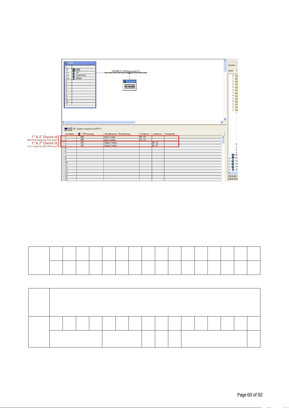
10.2 GSDML Configuration
Dword
(Only
read)
D31
D30
D29
D28
D27
D26
D25
D24
D23
D22
D21
D20
D19
D18
D17
D16
D15
D14
D13
D12
D11
D10
D9
D8
D7
D6
D5
D4
D3
D2
D1
D0
1st
Dword
By default, Indicated weight value is represented.
To represent other weight or calibration status, refer to next Dword.
2nd
Dword
Out 5 Out 4 Out 3 Out 2 Out
1
In 4 In 3 In 2 In
1
Error codes of FT-10
PN
Not in use
Zero
range
Gros
s
Net
MD
Read command response
Cmd
Flg
Profinet data structures of FT-10 PN includes 2 x Input 2 words and 2 x Output 2 words. GSDML
configuration for PLC programmers is shown in Figure 10.1.
Figure 10.1 - GSDML Configuration
10.3 Profinet Data Structure
FT-10 PN Output to PLC Input
Bitwise of a Dword:
FT-10 PN Output to PLC Input 2nd Dword
FT-10 Smart Process Indicator, Technical Manual, Rev. 1.0, January 2014
Page 62
Bit Number
2nd Dword Description
D31 … D24
Outputs
Output bit status ( Active = 1 )
D23 … D16
Inputs
Input bit status ( Active = 1 )
D15 … D12
Error Codes
of FT-10 PN
Bin
Dec
0000
0
No error found
0001
1
ADC out
0010
2
ADC over
0011
3
ADC under
0100
4
System Error
0101
5
In programming mode
0110
6
Low/High Voltage Error
D11 … D9
Not in use
D8
Zero Range
0
Weight is in zero range
1
Weight is out of zero range
D7
Indication
0
Gross
1
Net
D6
MD – Motion
Detection
0
Stable
1
Dynamic
D5 … D1
D5 … D1
Read
Command
Response
Read
Command
Response
(continuation
of previous
page)
00000
0
Indicated weight
00001
1
Gross weight
00010
2
Tare weight
00011
3
Calibration Status (Refer to Table 10.1 )
00100
01110
4
14
Not used
01111
15
Set Point-1 Low
10000
16
Set Point-1 High
10001
17
Set Point-2 Low
10010
18
Set Point-2 High
10011
19
Set Point-3 Low
10100
20
Set Point-3 High
10101
21
Set Point-4 Low
10110
22
Set Point-4 High
10111
23
Set Point-5 Low
11000
24
Set Point-5 High
11111
31
Use the Expanded Command list ( Refer to Table
10.2)
D0
CMD Flag
Toggles
The command is applied successfully
FT-10 Smart Process Indicator, Technical Manual, Rev. 1.0, January 2014
Page 63
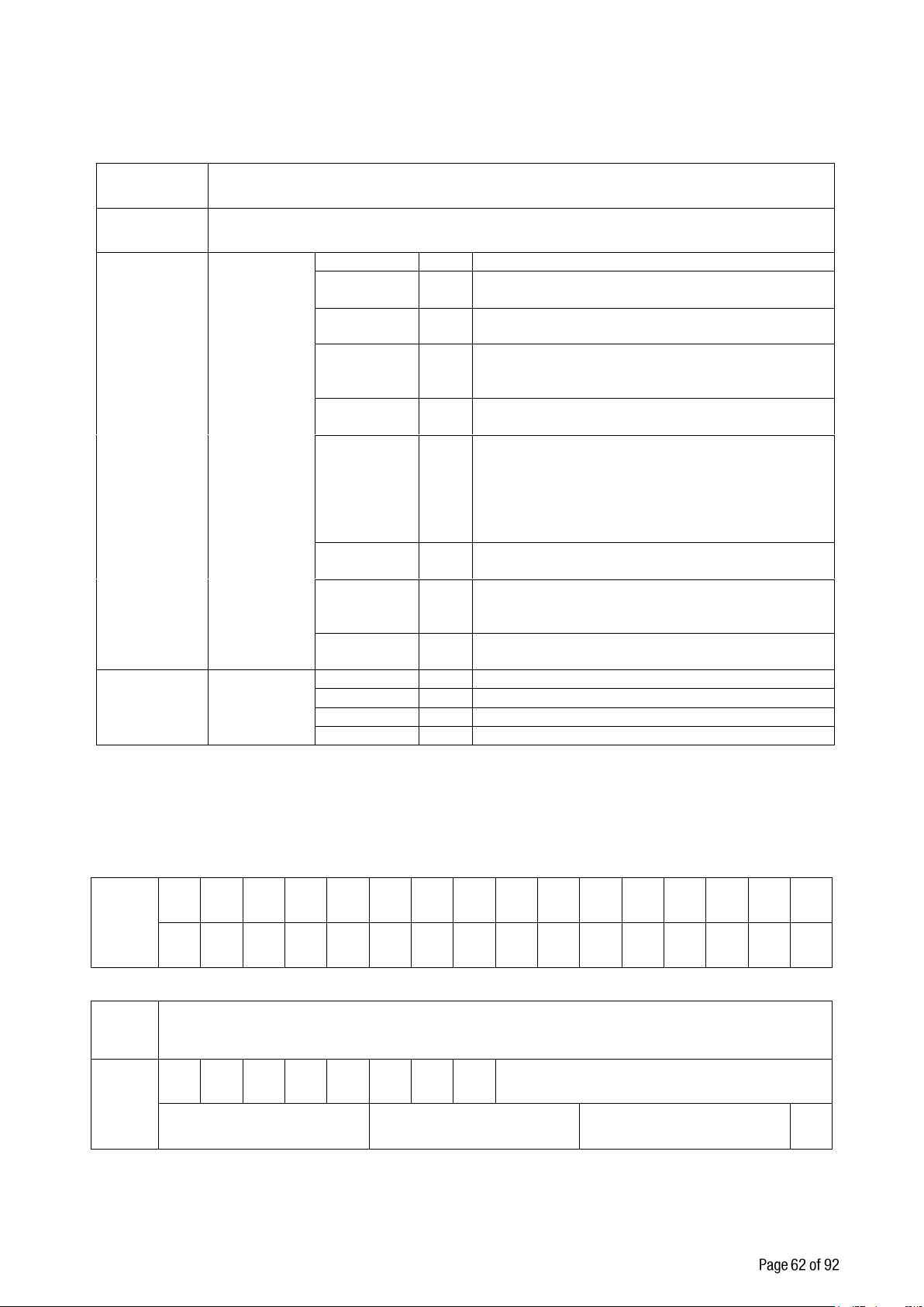
Calibration Status (always 32 bit integer)
Bit Number
1st Dword Description
D31 … D16
Not in use
D15 … D8
Calibration
Errors
Bin
Dec
Descriptions
0000 0001
1
Calibration Timeout
- Restart calibration
0000 0010
2
ADC Error
- Re-energize the instrument
0000 0011
3
Instrument can not be calibrating
- Check load cell cable
- Re-energize the instrument
0010 0010
34
Instrument can not be calibrating
- Load cell signal is very low or too high
0010 0011
35
Calibration Error
- Calibration loading is not enough
- Check test weight loading (Write test weight
value to 1
st
Dword of PLC Output to FT-10 PN
Input then restart the calibration)
- Check load cell connections
0010 0100
36
Calibration load value entry Error
- Test weight is too small. Increase the test weight
0010 0101
37
Scale unstable
- Wait until scale become stable
- Check grounding wiring
0010 0110
38
The Calibration DIP switch is not ON position.
- Check the calibration DIP switch.
D7 ... D0
Calibration
Process
Status
0000 0001
1
System ready for calibration
0000 0011
3
Zero calibration in process
0000 0100
4
Span calibration in process
0000 1001
9
Error ( Refer to Calibration Errors )
Dword
(R/W)
D31
D30
D29
D28
D27
D26
D25
D24
D23
D22
D21
D20
D19
D18
D17
D16
D15
D14
D13
D12
D11
D10
D9
D8
D7
D6
D5
D4
D3
D2
D1
D0
1st
Dword
Next Dword defines the usage of this Dword.
2nd
Dword
Out 5 Out 4 Out 3 Out 2 Out
1
Expanded Commands List
Not in use
Command List
Read Data Selection
New
CMD
1st Dword descriptions when read command is ‘Calibration Status’. Refer to 2nd Dword of PLC Output to FT10 PN Input.
PLC Output to FT-10 PN Input
Bitwise of a Dword:
FT-10 Smart Process Indicator, Technical Manual, Rev. 1.0, January 2014
Table 10.1 - Calibration status
Page 64
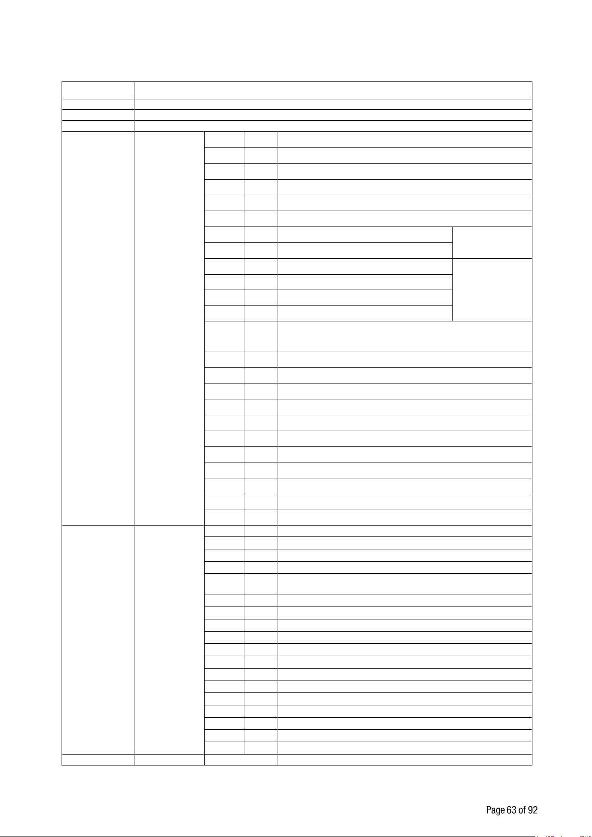
PLC Output to FT-10 PN Input 2nd Dword
Bit Number
2rd Dword descriptions
D31 … D24
Set / Reset digital outputs
D23 … D16
Expanded Commands List ( Refer to Table 10.2)
D15 … D11
Not in use
D10 … D6
D10 … D6
Command List
(continuation
of previous
page)
Bin
Dec
Commands
00000
0
None command is activated
00001
1
Zero
00010
2
Tare
00011
3
Clear
00100
4
Print
00101
5
Adjust zero calibration
Calibration
00110
6
Adjust span calibration
(1)
00111
7
Total Load Cell Capacity
(1)
eCal
Coefficients
Refer to par.
[313]
01000
8
Average mV/V value
(1)
01001
9
Dead Load value
(1)
01010
10
Save the coefficients of eCal
01011
01110
11
14
Not used
01111
15
Set Point-1 Low
(1)
10000
16
Set Point-1 High
(1)
10001
17
Set Point-2 Low
(1)
10010
18
Set Point-2 High
(1)
10011
19
Set Point-3 Low
(1)
10100
20
Set Point-3 High
(1)
10101
21
Set Point-4 Low
(1)
10110
22
Set Point-4 High
(1)
10111
23
Set Point-5 Low
(1)
11000
24
Set Point-5 High
(1)
11111
31
Use the Expanded Command list ( Refer to Table 10.2)
D5 ... D1
Read Data
Selection
00000
0
Indicated weight
00001
1
Gross weight
00010
2
Tare weight
00011
3
Calibration Status ( Refer to Table 10.1)
00100
01110
4
14
Not used
01111
15
Set Point-1 Low
( 2 )
10000
16
Set Point-1 High
10001
17
Set Point-2 Low
( 2 )
10010
18
Set Point-2 High
10011
19
Set Point-3 Low
( 2 )
10100
20
Set Point-3 High
10101
21
Set Point-4 Low
( 2 )
10110
22
Set Point-4 High
10101
21
Set Point-4 Low
( 2 )
10110
22
Set Point-4 High
10111
23
Set Point-5 Low
( 2 )
11000
24
Set Point-5 High
11111
31
Use the Expanded Command list ( Refer to Table 10.2)
D0
New CMD
Toggle
Apply commands which are listed in this table
(1) Write this command after writing values to 1st Dword, then apply this command with New CMD
(2) Only set point low addresses are used if the set point is programmed as standard.
FT-10 Smart Process Indicator, Technical Manual, Rev. 1.0, January 2014
Page 65
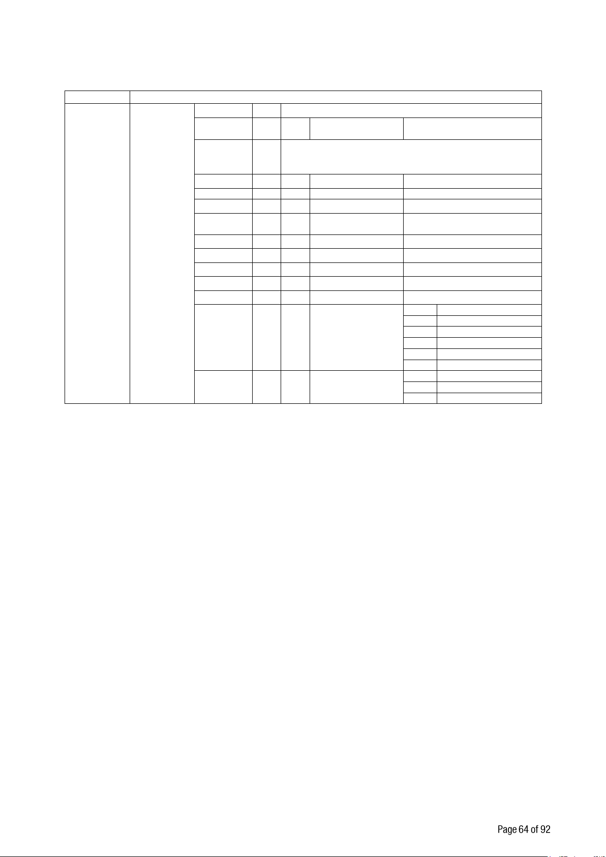
Expanded Command List (always 32 bit integer)
Bit No
Description
D23…D16
D23…D16
Expanded
Commands
List
(continuation
of previous
page)
Bin
Dec
Commands
00000000
0
R
Voltage of
Power Supply
Indicated with 0.1 VDC
increment.
00000001
00111111
1
63
Not in use
01000000
64
RW
Filter
(1)
Refer to par. [120] on page 29
01000001
65
RW
Power On Zero
(1)
Refer to par. [202] on page 30
01000010
66
RW
Zeroing Range
(1)
Refer to par. [203] on page 30
01000011
67
RW
Auto Zero Tracking
(1)
Refer to par. [204] on page 30
01000100
68
RW
Tare
(1)
Refer to par. [205] on page 30
01000101
69
RW
Motion Detector
(1)
Refer to par. [206] on page 30
01000110
70
RW
Stability Period
(1)
Refer to par. [207] on page 30
01000111
71
RW
Operation mode
(1)
Refer to par. [210] on page 31
01001000
72
RW
Capacity
(1)
Refer to par. [212] on page 31
01001001
73
RW
Decimal point
(1)
0
XXXXOO
1
XXXXXO
2
XXXXXX
3
XXXXX.X
4
XXXX.XX
5
XXX.XXX
01001010
74
RW
Increment
(1)
1
X1 2 X2 3 X5
The “D23 … D16” bits in 2
nd
Dword describes below.
(1) Write this command after writing values to 1st Dword then apply this command with New CMD.
Programming steps of frequent used ……
Reading a weight value:
1. Compare the D12…D15 bits of ‘FT-10 PN Output to PLC Input 2nd Dword’.
2. If there is not any error, read a weight value ( gross, net or tare),
Zero Calibration procedure:
1. Check the low byte of Calibration Status. it should be decimal '1' to start adjustment.
2. Write ‘Adjust Zero Calibration’ command and apply New CMD to start Zero calibration.
3. Check the low byte of Calibration Status. it is decimal '3' during zero calibration process.
4. The low byte of Calibration Status changes to decimal '1' at the end of the Zero calibration.
5. If the low byte of Calibration Status is '9', check the high byte of Calibration Status to understand the
calibration error.
Span Calibration procedure:
Check the low byte of Calibration Status. it should be decimal '1' to start adjustment.
Write ‘Adjust Span Calibration’ command after writing test weight values to 1
command with New CMD to start Span calibration.
1. Check the low byte of Calibration Status. it is decimal '4' during span calibration process.
2. The low byte of Calibration Status changes to decimal '1' at the end of the Span calibration.
3. If the low byte of Calibration Status is '9', check the high byte of Calibration Status to understand the
calibre ation error.
FT-10 Smart Process Indicator, Technical Manual, Rev. 1.0, January 2014
Table 10.2 - Expanded Command List
st
Dword, then apply this
Page 66

11. ETHERNET TCP/IP ( ONLY FT-10 EN )
Data Format
Description
Company samples
BSI Command set
Refer to Page 40
Continuous
Refer to Page 40
-
Fast Continuous
Refer to Page 40
-
Modbus TCP High-Low
Modbus TCP interfacing.
Refer to Page 67.
Interfacing with PLC.
Modbus TCP Low-High
Modbus TCP interfacing.
Refer to Page 67.
Interfacing with PLC.
Ethernet output of FT-10 EN is programmable to BSI command set, Continuous data output, Fast continuous
data output, Modbus TCP/IP High-Low, Modbus TCP/IP Low-High.
The first three data structures can be find in the related sections indicated in the table below.
You can find below the difference of Low-High and High-Low data formats and some companies using these
formats.
Table 11.1 - Ethernet output interfacing
[03-] Ethernet
This sub-block includes the parameters related with the Ethernet of FT-10 indicator.
[030 4 ] Data Format
0 : No data transfer.
1 : Continuous data output ( Page 39 )
2 : Print mode ( Parameter [ 040 ] on Page 26 )
3 : BSI command set ( Page 40 )
4 : Modbus TCP High-Low ( Page 67 )
5 : Modbus TCP Low-High ( Page 67 )
6 : Fast continuous mode ( Page 40 )
[031 01] Device Address
The address of FT-10 will be entered between 01 to 255.
[032 ] IP Address
The IP address will be entered as ” aaa.bbb.ccc.ddd ”. Default: “192.168.16.250”.
For changing the IP address, press the < Tare > key and enter the first 3 “a” digits of the IP address.
Press < Enter > key to access the following “b”, “c” and “d” address entries.
Press the < > key to access the next parameter.
[033 ] Subnet Mask Address
The IP address will be entered as ” aaa.bbb.ccc.ddd ”. Default: “255.255.255.000”.
For changing the IP address, press the < Tare > key and enter the first 3 “a” digits of the IP address.
Press < Enter > key to access the following “b”, “c” and “d” address entries.
Press the < > key to access the next parameter.
[034 ] Gateway Address
The IP address will be entered as ” aaa.bbb.ccc.ddd ”. Default: “192.168.16.253”.
For changing the IP address, press the < Tare > key and enter the first 3 “a” digits of the IP address.
Press < Enter > key to access the following “b”, “c” and “d” address entries.
Press the < > key to access the next parameter.
[035 ] Local Port
The local port will be entered between 00001 to 65535. Default: “502”.
FT-10 Smart Process Indicator, Technical Manual, Rev. 1.0, January 2014
Page 67

[036 0] Response Speed
0 : Modbus TCP Answer is sent immediately after Request is received.
1 : Modbus TCP Answer is delayed 20 msec after Request is received.
2 : Modbus TCP Answer is delayed 50 msec after Request is received.
This property is very helpful for slow PLC systems
11.1 Ethernet Parameters
There are 11 parameters for Ethernet network and Ethernet set up done by EtherX PC software over Local
Network Area as described in this section or You can entry from par. [ 03- ] blocks. EtherX PC software is
available in CD which is supplied together with the instrument.
Host Name
Device name of the instrument.
Default is ‘ ’.
IP Address
Obtain IP address manually.
Default is ‘192.168.16.250’.
Local Port
Ethernet connection port of the instrument.
Default is ‘502’.
Gateway
Network point that acts as an entrance to another network.
Default is ‘192.168.16.253’.
Subnet Mask
Describes IP address can be used in network.
Default is ‘255.255.255.0’.
Primary DNS
Obtain primary DNS manually.
Default is ‘208.67.222.222’.
Secondary DNS
Obtain secondary DNS manually.
Default is ‘208.67.220.220’.
Remote Connection
Automatic connection to any device on the network.
Default is ‘Disabled’.
Remote IP : IP address of the PC or Device to be connected automatically.
Remote Port : Ethernet connection point of PC or Device to be connected automatically.
FT-10 Smart Process Indicator, Technical Manual, Rev. 1.0, January 2014
Page 68
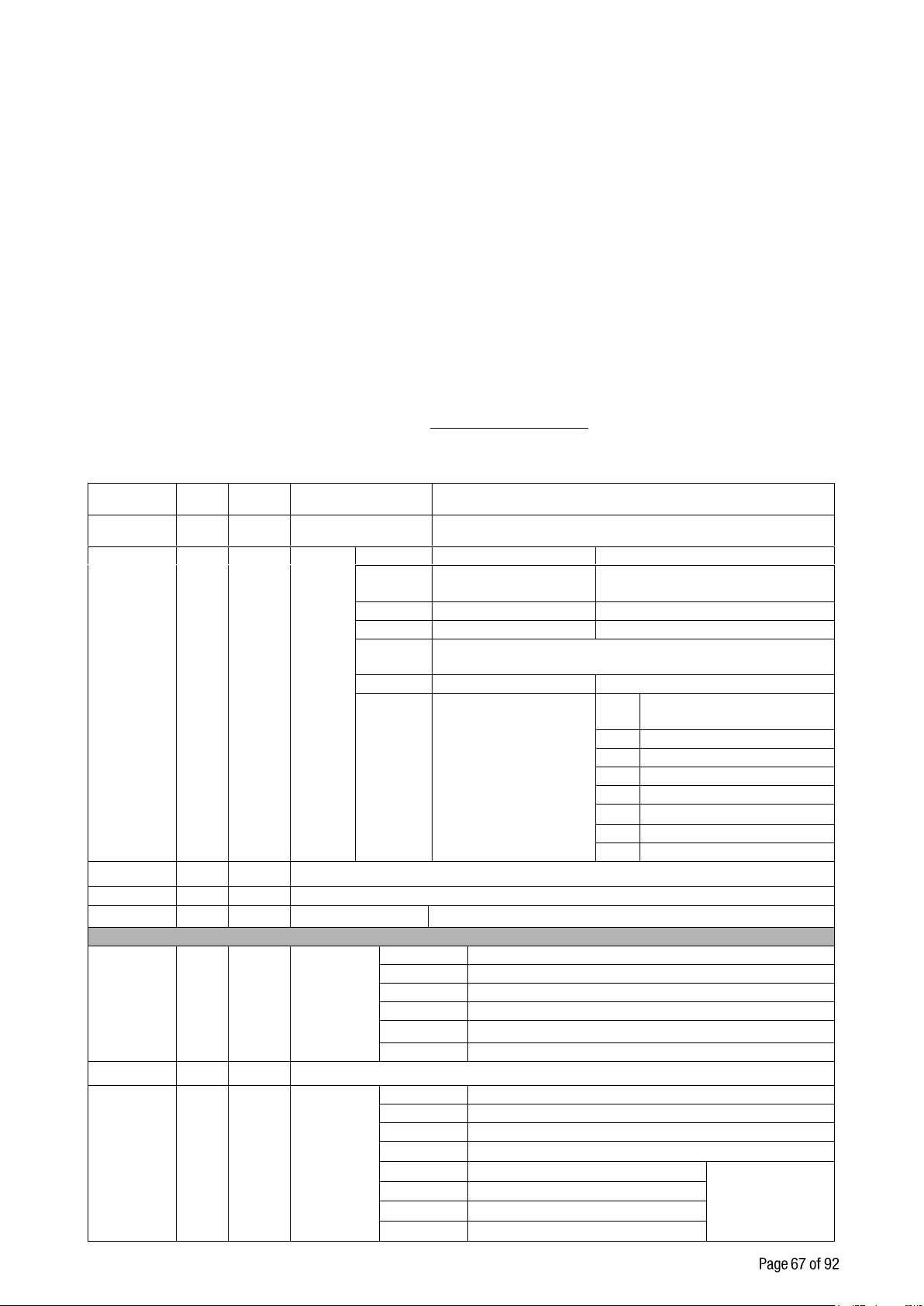
11.2 Modbus TCP Data Structure
Address
R/W
Word
Command
Definition
40001
R 2 Indicated weight
( Net if the indication is in Net )
40003
R 1 Status
D0
0 – System Ready
1 – System Busy
D1
0 – Error ( D13-D15
)
1 – Data ok
D2
0 – Weight Stable
1 – Weight unstable
D3
0 – Gross Mode
1 – Net mode
D4 –
D11
Not used
D12
0 – Out of zero range
1 – Weight is in zero range
D13
D14
D15
Error Code
De
c
Description
0
No Errors
1
ADC out of range
2
ADC over range
3
ADC under range
4
System error
5
In programming mode
6
Low/High voltage det.
40004
R 2 Tare weight
40006
R 2 Gross weight
40008
R 1 Status
Motion, Net mode, Data ok, (image of register 40003)
40009
R/W
1
Control
Dec
Description
0
None
1
Zero
2
Tare
3
Clear
4
Print
40010
R/W
20
Not used
40030
R/W
1
Calibratio
n
Dec
Description
0
None
188
Adjust Zero Calibration
220
Adjust Span Calibration
( 1 )
236
Total Load Cell Capacity
( 1 )
eCal
Coefficients
250
Average mV/V
( 1 )
171
Dead Load
( 1 )
23205
Save the coefficients of eCal
If the instrument is programmed for Modbus TCP/IP, it can be used as a Modbus TCP/IP slave on Ethernet
communication network. Functions code ‘0x03’ (Read Holding Registers) and ‘0x10’ (Preset Multiple Regs)
are supported.
Modbus TCP/IP High-Low: In two word registers, the data is stored to the registers in big-endian format.
Least significant word is stored to the highest register address; and most significant word is stored to the
lowest register address.
Modbus TCP/IP Low-High: In two word registers, the data is stored to the registers in little-endian format.
Least significant word is stored to the lowest register address; and most significant word is stored to the
highest register address.
Parameter set-up:
Set Ethernet Data Format : Modbus TCP/IP High-Low or Modbus TCP/IP Low-High
Ethernet Address : 01 to 255
Make the Ethernet parameter settings.
Please find Modbus information in the web site of http://www.modbus.org
Modbus TCP/IP Command Table;
FT-10 Smart Process Indicator, Technical Manual, Rev. 1.0, January 2014
Page 69
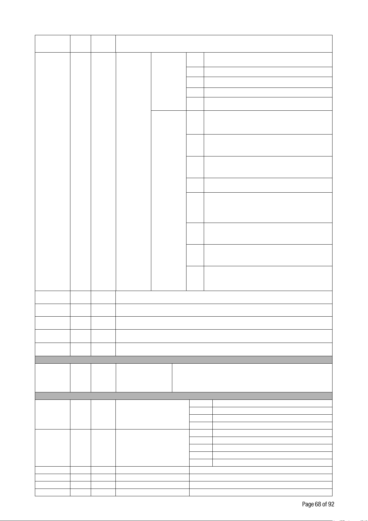
40031
R/W
2
Span Calibration Value / LC capacity / mV value / Dead load value
40033
R
1
Calibratio
n Status
D0 .. D7
Calibratio
n Process
Status
De
c
Description
1
Ready for calibration
3
Zero calibration in process …
4
Span calibration in process …
9
Error (Refer to D8 ... D15 )
D8 .. D15
Calibratio
n Errors
1
Calibration Timeout
- Restart calibration
2
ADC Error
- Re-energize the instrument
- If seen again, change the board.
3
Instrument can not be calibrating
- Check load cell cable
- Re-energize the instrument
34
Instrument can not be calibrating
- Load cell signal is very low or too high
35
Calibration Error
- Calibration loading is not enough
- Check test weight loading
- Check load cell connections
36
Calibration load value entry Error
- Test weight is too small. Increase the test
weight
37
Scale unstable
- Wait until scale become stable
- Check grounding wiring
38
The Calibration DIP switch is not ON
position.
- Check the calibration DIP switch.
40034
R/W
37
Not used
40071
R 1 Indicated weight
40072
R 1 Status
40073
R 1 Tare weight
40074
R 1 Gross weight
40100
R
1
Voltage of
Power Supply
Voltage of power supply is indicated with 0.1 V
increment.
For example: 23.4 VDC is indicated as integer 234
value.
40200
R 1 Status of Inputs
D0
Input-1
D1
Input-2
D2
Input-3
D3
Input-4
40201
R/W
1
Status of Outputs
D0
Output-1
D1
Output-2
D2
Output-3
D3
Output-4
D4
Output-5
40202
R/W
2
Setpoint 1 Low
( 2 )
40204
R/W
2
Setpoint 1 High
40206
R/W
2
Setpoint 2 Low
( 2 )
40208
R/W
2
Setpoint 2 High
FT-10 Smart Process Indicator, Technical Manual, Rev. 1.0, January 2014
Page 70
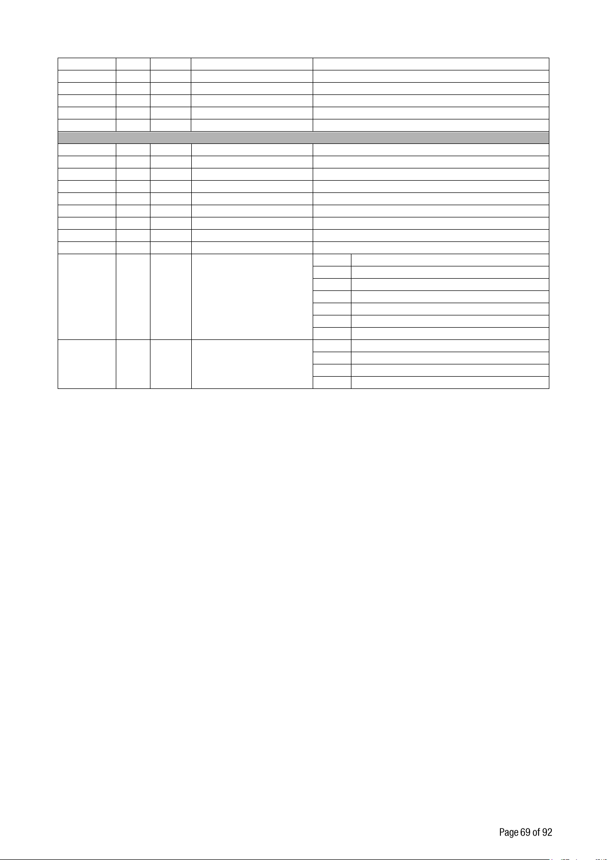
40210
R/W
2
Setpoint 3 Low
( 2 )
40212
R/W
2
Setpoint 3 High
40214
R/W
2
Setpoint 4 Low
( 2 )
40216
R/W
2
Setpoint 4 High
40218
R/W
2
Setpoint 5 Low
( 2 )
40220
R/W
2
Setpoint 5 High
42000
R/W
1
Filter
Refer to parameter [120] on page 29
42001
R/W
1
Power On Zero
Refer to parameter [202] on page 30
42002
R/W
1
Zeroing Range
Refer to parameter [203] on page 30
42003
R/W
1
Auto Zero Tracking
Refer to parameter [204] on page 30
42004
R/W
1
Tare
Refer to parameter [205] on page 30
42005
R/W
1
Motion Detector
Refer to parameter [206] on page 30
42006
R/W
1
Stability Period
Refer to parameter [207] on page 30
42007
R/W
1
Operation mode
Refer to parameter [210] on page 31
42008
R/W
2
Capacity
Refer to parameter [212] on page 31
42010
R/W
1
Decimal point
Dec
Description
0
XXXXOO
1
XXXXXO
2
XXXXXX
3
XXXXX.X
4
XXXX.XX
5
XXX.XXX
42011
R/W
1
Increment
Dec
Description
1
X 1 2 X 2 3 X 5
(1) Write this command after writing values to 40031-32 addresses.
(2) Only set point low addresses are used if the set point is programmed as standard.
Programming steps of frequent used ……
Reading a weight value:
1. Read 40003,
2. Check D0=0 and D1=1,
3. If yes, read a weight value ( gross, net or tare),
4. If D0=1, check D0 until system ready,
5. If D1=0, check the error code.
Zero Calibration procedure:
1. Check the low byte of 40033. it should be decimal '1' to start adjustment.
2. Load the decimal '188' to 40030 to start Zero calibration.
3. Check the low byte of 40033. it is decimal '3' during zero calibration process.
4. The low byte of 40033 changes to decimal '1' at the end of the Zero calibration.
5. If the low byte of 40033 is '9', check the high byte of 40033 to understand the calibration error.
Span Calibration procedure:
1. Check the low byte of 40033. it should be decimal '1' to start adjustment.
2. First load the span value to 40031-32 and then load the decimal '220' to 40030 to start Span
calibration.
3. Check the low byte of 40033. it is decimal '4' during span calibration process.
4. The low byte of 40033 changes to decimal '1' at the end of the Span calibration.
5. If the low byte of 40033 is '9', check the high byte of 40033 to understand the calibration error.
EXPLANATION:
Attention: For hardware connection details, please refer to the related hardware descriptions in this
manual.
Exception codes:
1: Function code is not supported.
2: Out of beginning and ending address range.
3: Invalid value entrance or wrong byte number.
4: Operation error.
FT-10 Smart Process Indicator, Technical Manual, Rev. 1.0, January 2014
Page 71
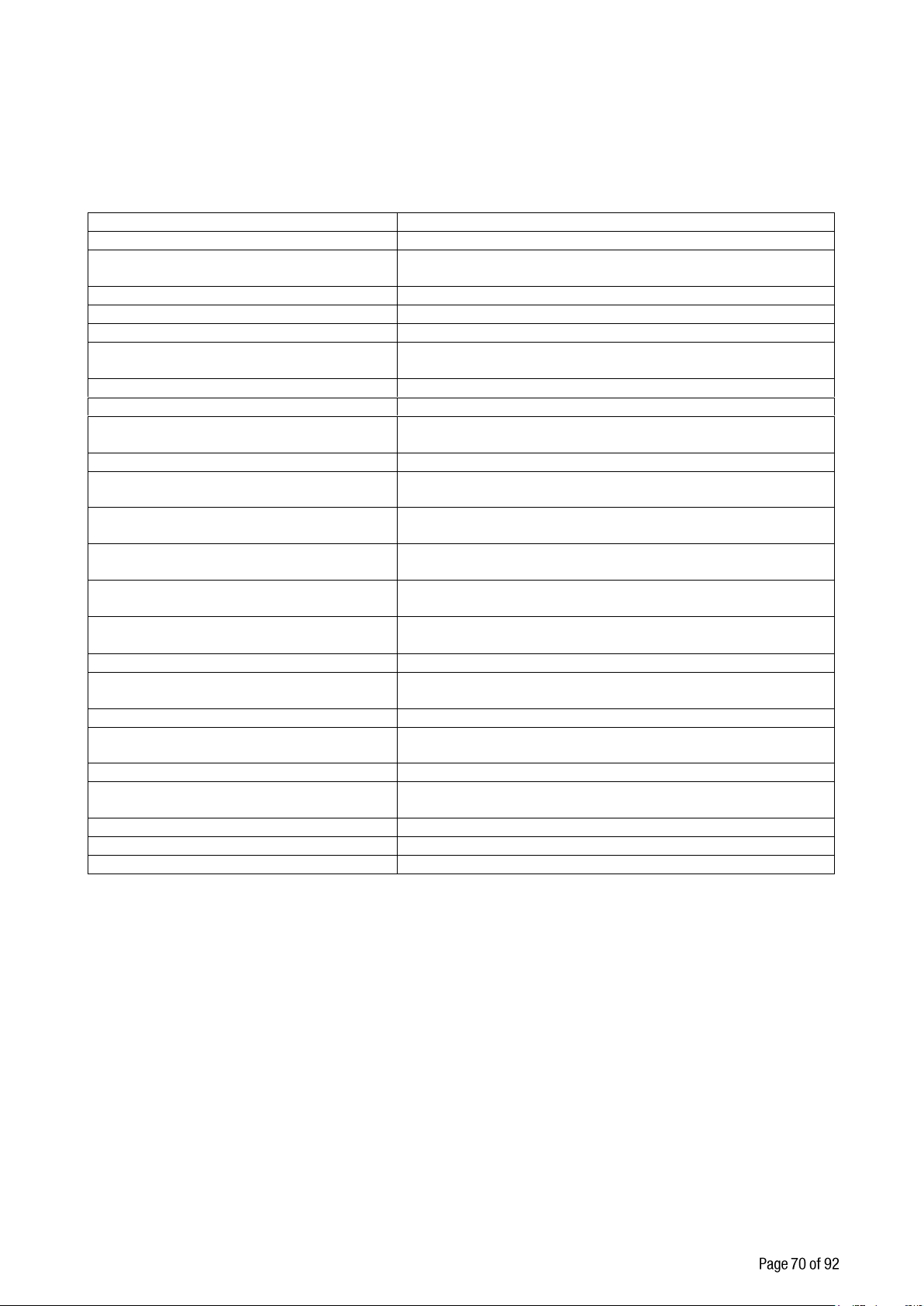
Command Examples:
Description
Hex
Request weight data
01,03,00,00,00,02
Answer of request weight
(weight value is 100000 )
01,03,04,00,01,86,A0
Request status data
01,03,00,02,00,01
Taring
01,10,00,08,00,01,02,00,02
Request tare data
01,03,00,03,00,02
Answer of request tare
(tare value is 10000 )
01,03,04,00,00,27,10
Zero Command
01,10,00,08,00,01,02,00,01
Request Calibration Status
01,03,00,20,00,01
Answer of request Calibration Status
(Instrument is ready for calibration)
01,03,02,00,01
Zero Calibration
01,10,00,1D,00,01,02,00,BC
Span Calibration Command with Span
value 50000
01,10,00,1D,00,03,06,00,DC,00,00,C3,50
Total LC capacity Command with
Total LC capacity value 100000
01,10,00,1D,00,03,06,00,EC,00,01,86,A0
Average mV/V Command with
Average mV/V value 1.9999
01,10,00,1D,00,03,06,00,FA,00,00,4E,1F
Dead load Command with Dead load
value 12345
01,10,00,1D,00,03,06,00,AB,00,00,30,39
Save the coefficients of eCal
Command
01,10,00,1D,00,01,02,5A,A5
Read Voltage of Power Supply value
01,03,00,63,00,01
Answer of Voltage of Power Supply
(Voltage of Power Supply is 23,5 V)
01,03,02,00,EB
Read digital inputs
01,03,00,C7,00,01
Answer of digital inputs
(Input-2 is active)
01,03,02,00,02
Read digital outputs
01,03,00,C8,00,01
Answer of digital outputs
(Output-3 is Active)
01,03,02,00,04
Read Setpoint-1 Low
01,03,00,C9,00,02
Answer of Setpoint-1 Low
01,03,04,00,00,03,E8
Load Set point 1 Low = 5000
01,10,00,C9,00,02,04,00,00,13,88
Performing Read and Write operations according (Modbus TCP/IP High-Low) to hex system with the
instrument set to address “0x01”. MBAP (Modbus Application Protocol) Header is not included to the below
Modbus TCP/IP application data units.
Below you will find some command samples;
FT-10 Smart Process Indicator, Technical Manual, Rev. 1.0, January 2014
Page 72
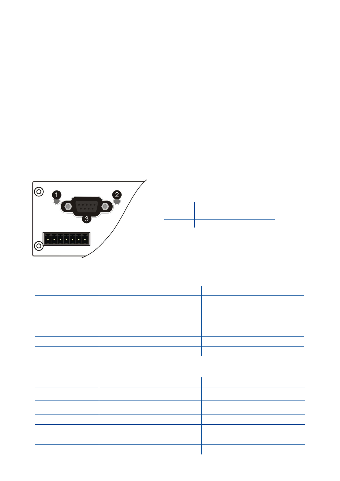
Page 71 of 82
12. CANOPEN ( ONLY FT-10 CO )
State
Indication
Comment
Off
Not online / No power
Check power and cable
Green
On-line, data exchange
-
Green, blinking
On-line, initializing
-
Green, single flash
Stopped
Check hardware damages
Green, flickering
Auto baudrate detection in progress
-
Red
CANopen configuration error
Check EDS file
State
Indication
Comment
Off
-
No power or CANopen module is in
initialization state
Red, single flash
Warning limit reached
A bus error counter reached or
exceeded its warning level
Red, flickering
LSS
LSS services in progress
Red, double flash
Error count event
A guard- (NMT-Slave or NMTmaster) or heartbeat event
(Heartbeat consumer) has occurred.
Red
Bus off (Fatal Event)
Bus off.
1
Run LED
2
Error LED
3
CANopen interface
After programming CANopen related parameters of the FT-10 PB indicator, you can communicate with the
instrument. EDS file is available on CD which is supplied together with the instrument.
Automatically detected and supported baud rates are 10 kbps, 50 kbps, 100 kbps, 125 kbps, 250 kbps, 500
kbps, 800 kbps, 1 Mbps, Autobaud (default).
[07-] CANopen
This sub-block includes the parameters related with the CANopen interfaces of FT-10 indicator.
[070 0] Data Format
0 : Signed 32 bit integer, no decimal point implied
1 : 32 bit float, decimal point implied
[071 000] Rack Address
The CANopen rack address of FT-10 will be entered via keypad between 001 to 126.
There are 2 LED’s near the CANopen connector which are;
Run LED
Error LED
FT-10 Smart Process Indicator, Technical Manual, Rev. 1.0, January 2014
Page 73

Page 72 of 82
12.1 EDS Configuration
CANopen data structures of FT-10 CO includes 1 x TxPDO ( 64 bit ) and 1 x RxPDO ( 64 bit ). EDS
configuration for PLC programmers is shown in Figure 12.1.
Figure 12.1 - EDS Configuration
FT-10 Smart Process Indicator, Technical Manual, Rev. 1.0, January 2014
Page 74
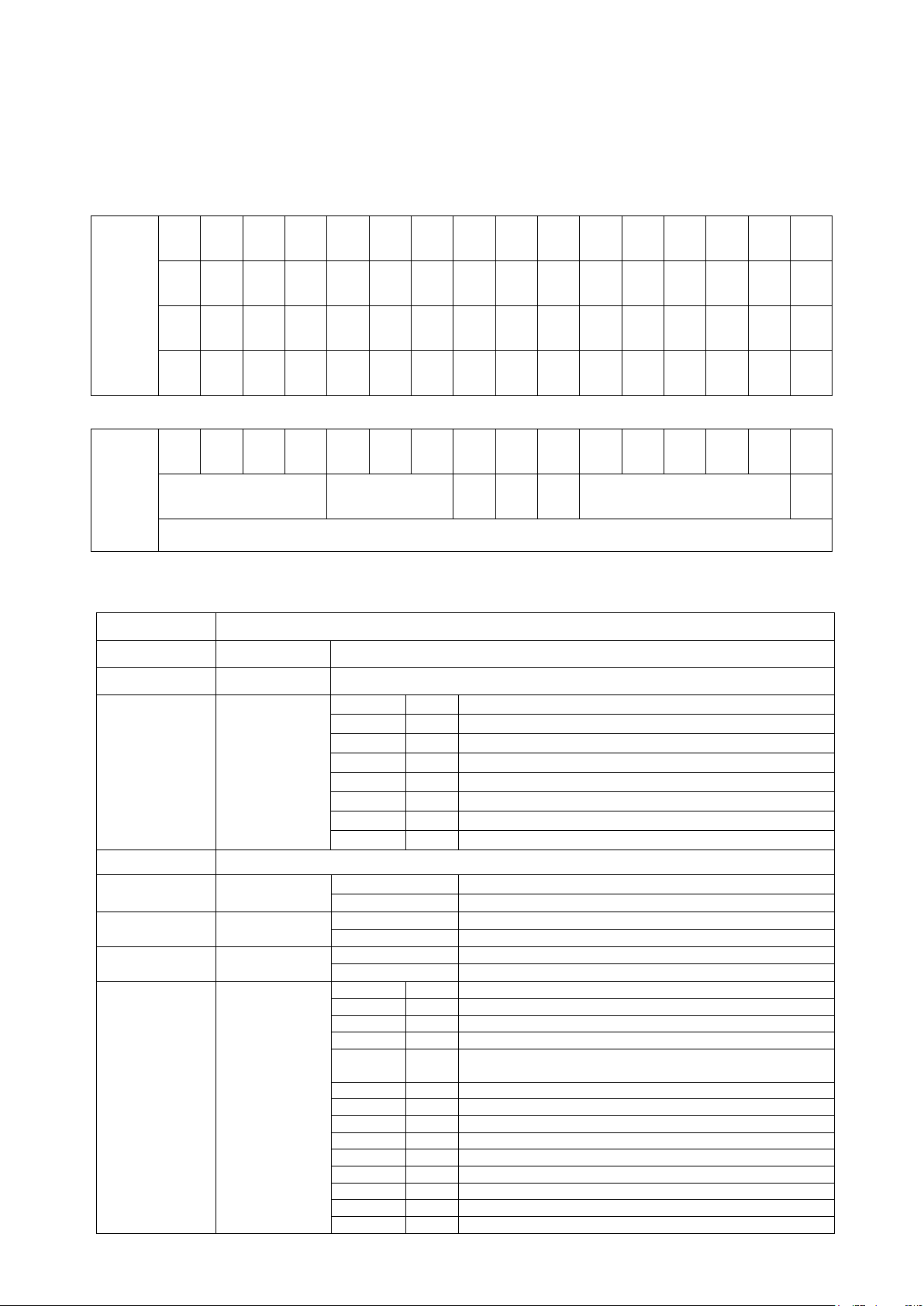
Page 73 of 82
12.2 CANopen Data Structure
Unsigned
Long
(Only
read)
D63
D62
D61
D60
D59
D58
D57
D56
D55
D54
D53
D52
D51
D50
D49
D48
D47
D46
D45
D44
D43
D42
D41
D40
D39
D38
D37
D36
D35
D34
D33
D32
D31
D30
D29
D28
D27
D26
D25
D24
D23
D22
D21
D20
D19
D18
D17
D16
D15
D14
D13
D12
D11
D10
D9
D8
D7
D6
D5
D4
D3
D2
D1
D0
TxPDO 1
(T_UL1)
Out 5 Out 4 Out 3 Out 2 Out
1
In 4 In 3 In 2 In
1
Error codes of FT-10 CO
Not in use
Zero
range
Gross
Net
MD
Read command response
Cmd
Flg
By default, Indicated weight value is represented.
To represent other weight or calibration status, refer to D33…D37.
Bit Number
TxPDO 1 (T_UL1) Description
D63 … D56
Outputs
Output bit status ( Active = 1 )
D55 … D48
Inputs
Input bit status ( Active = 1 )
D47 … D44
Error Codes of
FT-10 CO
Bin
Dec
0000
0
No error found
0001
1
ADC out
0010
2
ADC over
0011
3
ADC under
0100
4
System Error
0101
5
In programming mode
0110
6
Low/High Voltage Error
D43 … D41
Not in use
D40
Zero Range
0
Weight is in zero range
1
Weight is out of zero range
D39
Indication
0
Gross
1
Net
D38
MD – Motion
Detection
0
Stable
1
Dynamic
D37 … D33
D37 … D33
Read
Command
Response
Read
Command
Response
00000
0
Indicated weight
00001
1
Gross weight
00010
2
Tare weight
00011
3
Calibration Status (Refer to Table 12.1)
00100
01110
4
14
Not used
01111
15
Set Point-1 Low
10000
16
Set Point-1 High
10001
17
Set Point-2 Low
10010
18
Set Point-2 High
10011
19
Set Point-3 Low
10100
20
Set Point-3 High
10101
21
Set Point-4 Low
10110
22
Set Point-4 High
10111
23
Set Point-5 Low
FT-10 CO Output to PLC Input
Bitwise of a Ulong:
FT-10 CO Output to PLC Input TxPDO 1 (T_UL1)
FT-10 Smart Process Indicator, Technical Manual, Rev. 1.0, January 2014
Page 75
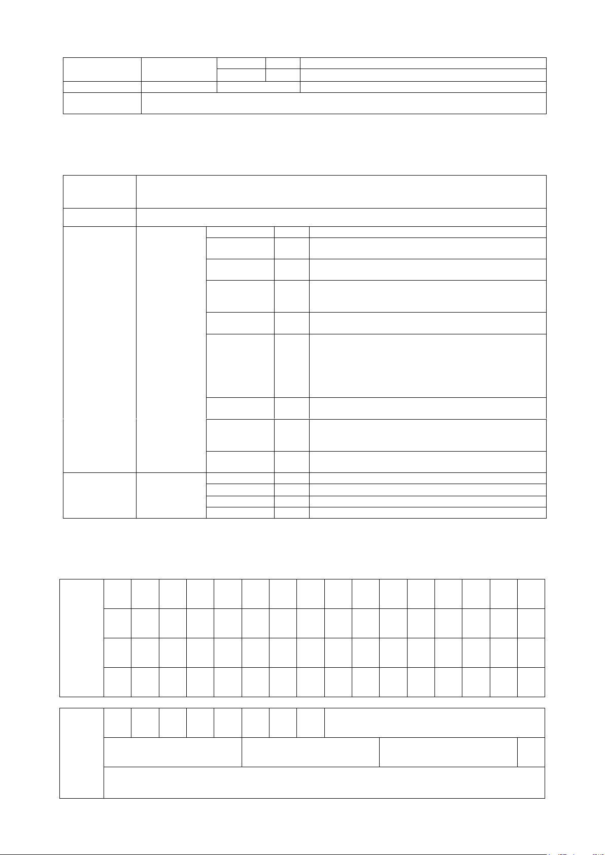
Page 74 of 82
(continuation of
previous page)
11000
24
Set Point-5 High
11111
31
Use the Expanded Command list ( Refer to Table 12.2)
D32
CMD Flag
Toggles
The command is applied successfully
D31…D0
By default, Indicated weight value is represented.
To represent other weight or calibration status, refer to D33~D37.
Bit Number
Low Dword of TxPDO 1 (T_UL1) Description
D31 … D16
Not in use
D15 … D8
Calibration
Errors
Bin
Dec
Descriptions
0000 0001
1
Calibration Timeout
- Restart calibration
0000 0010
2
ADC Error
- Re-energize the instrument
0000 0011
3
Instrument can not be calibrating
- Check load cell cable
- Re-energize the instrument
0010 0010
34
Instrument can not be calibrating
- Load cell signal is very low or too high
0010 0011
35
Calibration Error
- Calibration loading is not enough
- Check test weight loading (Write test weight value to
RxPDO 1 (R_DW1) of PLC Output to FT-10 CO Input
then restart the calibration)
- Check load cell connections
0010 0100
36
Calibration load value entry Error
- Test weight is too small. Increase the test weight
0010 0101
37
Scale unstable
- Wait until scale become stable
- Check grounding wiring
0010 0110
38
The Calibration DIP switch is not ON position.
- Check the calibration DIP switch.
D7 ... D0
Calibration
Process
Status
0000 0001
1
System ready for calibration
0000 0011
3
Zero calibration in process
0000 0100
4
Span calibration in process
0000 1001
9
Error ( Refer to Calibration Errors )
Unsigned
Long
(R/W)
D63
D62
D61
D60
D59
D58
D57
D56
D55
D54
D53
D52
D51
D50
D49
D48
D47
D46
D45
D44
D43
D42
D41
D40
D39
D38
D37
D36
D35
D34
D33
D32
D31
D30
D29
D28
D27
D26
D25
D24
D23
D22
D21
D20
D19
D18
D17
D16
D15
D14
D13
D12
D11
D10
D9
D8
D7
D6
D5
D4
D3
D2
D1
D0
RxPDO 1
(R_UL1)
Out 5 Out 4 Out 3 Out 2 Out
1
Expanded Commands List
Not in use
Command List
Read Data Selection
New
CMD
D33~D37 bits defines the usage of this Dword.
Calibration Status (always 32 bit integer)
Low Dword of TxPDO 1 (T_UL1) descriptions when read command is ‘Calibration Status’. Refer to RxPDO 1
(R_UL1) of ‘PLC Output to FT -10 CO Input’.
Table 12.1 - Calibration status
PLC Output to FT-10 CO Input
Bitwise of a Ulong:
FT-10 Smart Process Indicator, Technical Manual, Rev. 1.0, January 2014
Page 76
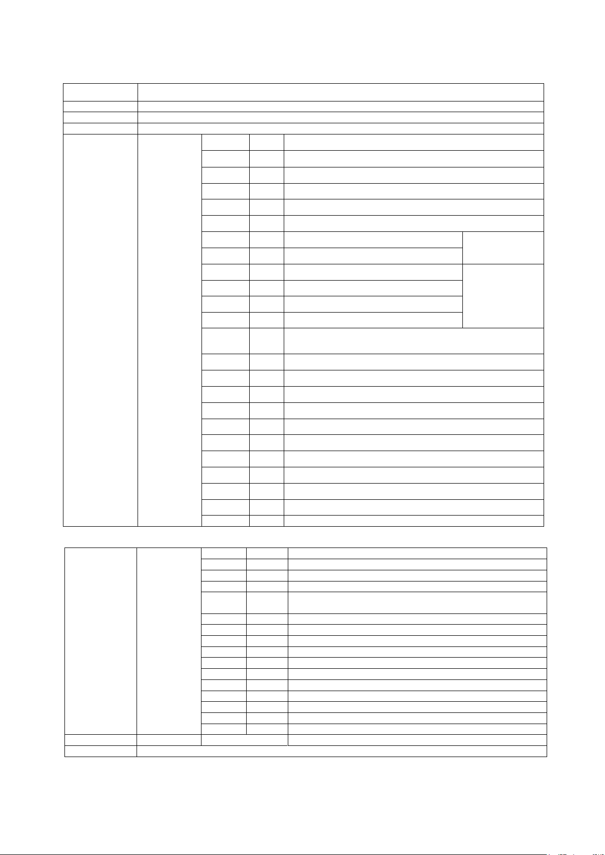
Page 75 of 82
PLC Output to FT-10 CO Input RxPDO 1 (R_UL1)
Bit Number
RxPDO 1 (R_UL1) descriptions
D63 … D56
Set / Reset digital outputs
D55 … D48
Expanded Commands List ( Refer to Table 12.2)
D47 ... D43
Not in use
D42 … D38
Command
List
Bin
Dec
Commands
00000
0
None command is activated
00001
1
Zero
00010
2
Tare
00011
3
Clear
00100
4
Print
00101
5
Adjust zero calibration
Calibration
00110
6
Adjust span calibration
( 1 )
00111
7
Total Load Cell Capacity
( 1 )
eCal
Coefficients
Refer to par.
[313]
01000
8
Average mV/V value
( 1 )
01001
9
Dead Load value
( 1 )
01010
10
Save the coefficients of eCal
01011
01110
11
14
Not used
01111
15
Set Point-1 Low
( 1 )
10000
16
Set Point-1 High
( 1 )
10001
17
Set Point-2 Low
( 1 )
10010
18
Set Point-2 High
( 1 )
10011
19
Set Point-3 Low
( 1 )
10100
20
Set Point-3 High
( 1 )
10101
21
Set Point-4 Low
(1)
10110
22
Set Point-4 High
(1)
10111
23
Set Point-5 Low
(1)
11000
24
Set Point-5 High
(1)
11111
31
Use the Expanded Command list ( Refer to Table 12.2)
D37 ... D33
Read Data
Selection
00000
0
Indicated weight
00001
1
Gross weight
00010
2
Tare weight
00011
3
Calibration Status ( Refer to Table 12.1)
00100
01110
4
14
Not used
01111
15
Set Point-1 Low
( 2 )
10000
16
Set Point-1 High
10001
17
Set Point-2 Low
( 2 )
10010
18
Set Point-2 High
10011
19
Set Point-3 Low
( 2 )
10100
20
Set Point-3 High
10101
21
Set Point-4 Low
( 2 )
10110
22
Set Point-4 High
10111
23
Set Point-5 Low
( 2 )
11000
24
Set Point-5 High
11111
31
Use the Expanded Command list ( Refer to Table 12.2)
D34
New CMD
Toggle
Apply commands which are listed in this table
D33~D0
D33~D37 bits defines the usage of this Dword.
(1) Write this command with writing values to D0…D33 bits then apply New CMD.
(2) Only set point low addresses are used if the set point is programmed as standard.
FT-10 Smart Process Indicator, Technical Manual, Rev. 1.0, January 2014
Page 77
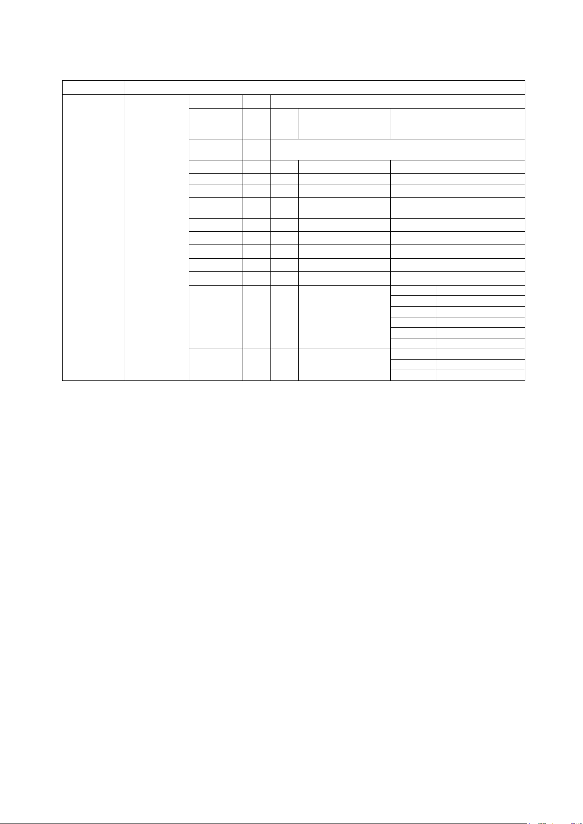
Page 76 of 82
Expanded Command List (always 32 bit integer)
Bit No
Description
D48…D55
Expanded
Commands
List
Bin
Dec
Commands
00000000
0
R
Voltage of
Power Supply
Voltage of power supply is
indicated with 0.1 VDC
increment.
00000001
00111111
1
63
Not in use
01000000
64
RW
Filter
(1)
Refer to par. [120] on page 29
01000001
65
RW
Power On Zero
(1)
Refer to par. [202] on page 30
01000010
66
RW
Zeroing Range
(1)
Refer to par. [203] on page 30
01000011
67
RW
Auto Zero Tracking
(1)
Refer to par. [204] on page 30
01000100
68
RW
Tare
(1)
Refer to par. [205] on page 30
01000101
69
RW
Motion Detector
(1)
Refer to par. [206] on page 30
01000110
70
RW
Stability Period
(1)
Refer to par. [207] on page 30
01000111
71
RW
Operation mode
(1)
Refer to par. [210] on page 31
01001000
72
RW
Capacity
(1)
Refer to par. [212] on page 31
01001001
73
RW
Decimal point
(1)
0
XXXXOO
1
XXXXXO
2
XXXXXX
3
XXXXX.X
4
XXXX.XX
5
XXX.XXX
01001010
74
RW
Increment
(1)
1
X1
2
X2
3
X5
The “D48 … D55” bits in RxPDO describes below.
Table 12.2 - Expanded Command List
(1) Write this command with writing values to D0~D33 bits then apply New CMD.
Programming steps of frequent used ……
Reading a weight value:
1. Check the D44…D47 bits of ‘TxPDO 1 (T_UL1)’.
2. If there is not any error, read a weight value ( gross, net or tare),
Zero Calibration procedure:
1. Check the low byte of Calibration Status. it should be decimal '1' to start adjustment.
2. Write ‘Adjust Zero Calibration’ command and apply New CMD to start Zero calibration.
3. Check the low byte of Calibration Status. it is decimal '3' during zero calibration process.
4. The low byte of Calibration Status changes to decimal '1' at the end of the Zero calibration.
5. If the low byte of Calibration Status is '9', check the high byte of Calibration Status to understand the
calibration error.
Span Calibration procedure:
1. Check the low byte of Calibration Status. it should be decimal '1' to start adjustment.
2. Write ‘Adjust Span Calibration’ command with writing test weight values to Low Dword of RxPDO1
(R_UL1), then apply New CMD to start Span calibration.
3. Check the low byte of Calibration Status. it is decimal '4' during span calibration process.
4. The low byte of Calibration Status changes to decimal '1' at the end of the Span calibration.
5. If the low byte of Calibration Status is '9', check the high byte of Calibration Status to understand
the calibration error.
FT-10 Smart Process Indicator, Technical Manual, Rev. 1.0, January 2014
Page 78
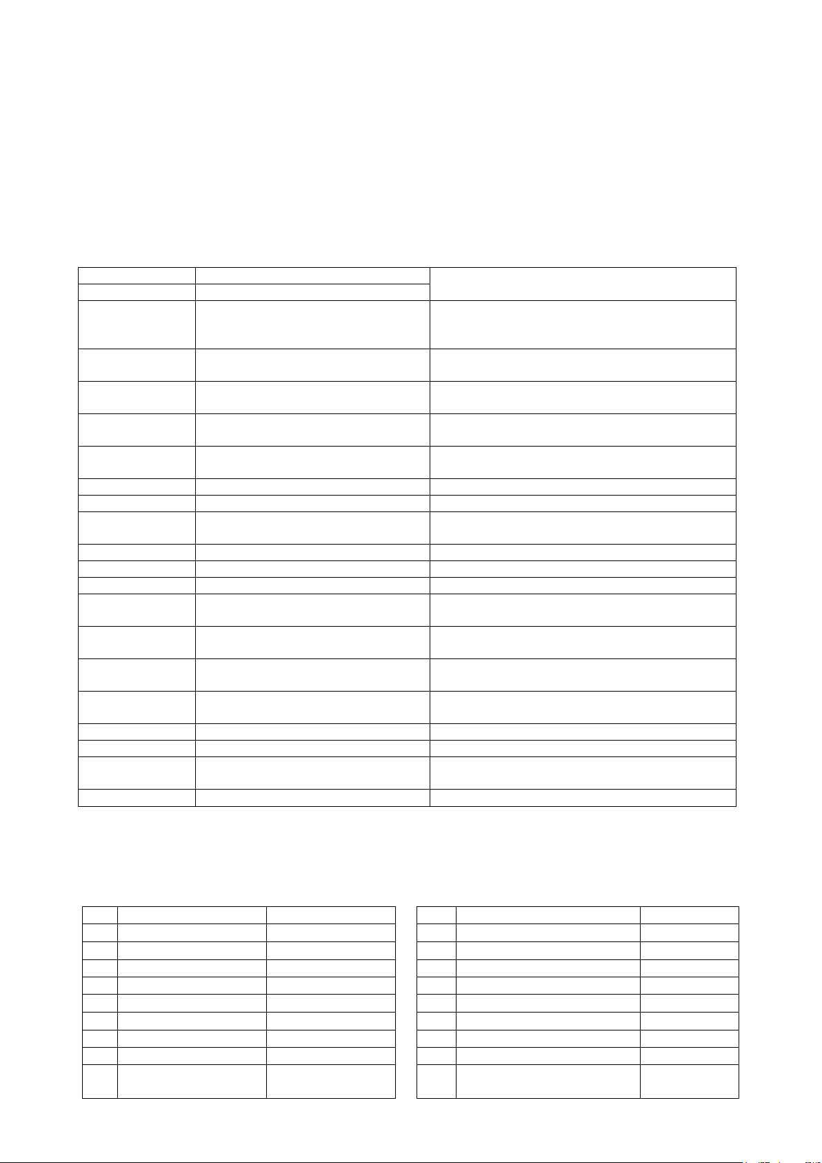
Page 77 of 82
13. TROUBLE SHOOTING
ERROR
CODE
DESCRIBTION
THINGS TO DO
Under
Weight is too low
- Check the load
- Load cell or instrument could be broken.
Over
Over Load
ADC Out
Load exceeds the operation
range
- Check the load
- Check the calibration
- Load cell or instrument could be broken.
Err 1
ADC error
- Re-energize indicator
- Call FLINTEC
Err 2
ADC error
- Re-energize indicator
- Call FLINTEC
Err 3
Indicator cannot be calibrated
- Check load cell cable and load then start
calibration again
Err 10
EEPROM error
- Configure the instrument
- EEPROM broken
Err 20
Calibration error
- Calibrate the indicator..
Err 21
Configuration error
- Configure the indicator.
Err 22
Tare, CN, Total weight and the
SP in use error
- Check SP, PT and ID entries.
- Check Tare, CN and Total weight
Err 26
Set point error
- Reload Set points.
Err 27
Indicator is not calibrated
- Calibrate the indicator
Err 30
Processor Error
- Call FLINTEC
Err 34
Indicator can not be calibrating
- Load cell signal is negative , very low or too
high
Err 35
Calibration Error
- Calibration loading is not enough.
- Check test weight loading.
Err 36
Calibration load value entry Error
- Test weight is too small. Increase the test
weight.
Err 37
Scale unstable
- Wait until scale become stable.
- Check grounding wiring.
Err 47
Main pcb info error
- Call FLINTEC
Err 61
Eeprom is not installed or broken
- Call FLINTEC
Err 70
Modbus selection error
- Check data format of other interfaces.
- Other interfaces should not be Modbus.
E XXXX
Hardware error
- Call FLINTEC
0--
Interface Block
14-
Entries
00-
RS 232C
142
Label No entrance
000
Data Format
3 = BSI
2--
Scale Block
001
Baud rate
3 = 9600
20-
Set up
003
Address
0
200
Approved
0 = No
004
Data length and Parity
0 = 8 bit, no parity
201
Increased indication
0 = x10 key
005
Checksum
0 = Disable
202
Power on zero
0 = Disable
006
Carriage Return
1 = Enable
203
Zero range
3 = ± %50
007
Line Feed
1 = Enable
204
Auto zero tracking
0 = Disable
008
Response Speed
0 = immediately
205
Tare
1 = With Tare
Key
FT-10 weighing indicator had been designed as a very reliable and virtually error free instrument. However, if
an error occurs, do not attempt to repair the equipment before understanding what caused the error. Note
the problems you have with your instrument and the error messages shown on the display. Then try to solve
the problem according to the error table given below.
Error Table
14. PARAMETER- DEFAULT TABLE
FT-10 Smart Process Indicator, Technical Manual, Rev. 1.0, January 2014
Page 79
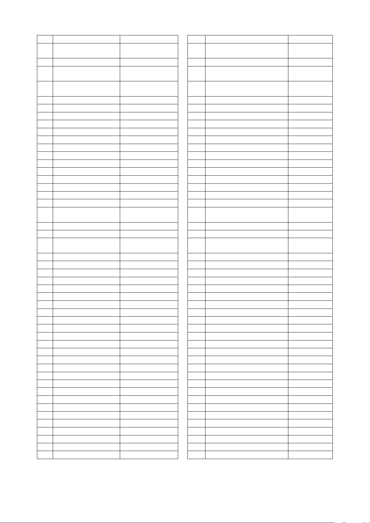
Page 78 of 82
01-
RS 485
206
Motion detector
2 = ± 1e
010
Data Format
5 = Modbus RTU
Lo-Hi
207
Stability Period
0.0
011
Baud rate
3 = 9600
21-
Scale Build
013
Address
1
210
Scale Type
0 = Single
Range
014
Data length and Parity
0 = 8 bit, no parity
212
Capacity / d
6000 kg / 1
kg
015
Checksum
0 = Disable
214
Unit
1 = kg
016
Carriage Return
1 = Enable
3--
Calibration Block
017
Line Feed
1 = Enable
30-
Calibration
018
Response Speed
0 = immediately
300
Gravity
03-
Ethernet
301
Calibration
030
Ethernet Data Format
0 = No
302
Linearity Correction
031
Ethernet Address
1
31-
Adjustment
032
IP Address
192.168.016.250
310
Zero adjustment
033
Gateway Address
192.168.016.253
311
Span adjustment
034
Subnet Mask
255.255.255.000
312
Span adjustment under load
035
Local Port
502
313
eCal Calibration
036
Response Speed
0 = immediately
4--
Analogue Output Block
04-
Printer
40-
Signal Selection
040
Print out format
2 = Multi line
400
Analogue Output Mode
0 = 4-20mA
041
CN
1 = Will be printed
401
Set Analogue output to calib.
range
042
Minimum print
20
41-
Zero Adjustment
043
Print method
0 = With Print Key
410
Coarse Zero Adjustment
044
Line feed before
printing
00 = 0 F + 0 LF
411
Fine Zero Adjustment
045
Line feed after printing
04 = 0 F + 2 LF
42-
Span Adjustment
046
Form feed
0 = Disable
420
Coarse Span Adjustment
047
Space on the left
3
421
Fine Span Adjustment
048
Quantity of copies
1
70-
Digital Output Functions
05-
Profibus DP
700
Output 1
0 = No
050
Data Format
0 = signed 32 bit
701
Output 2
0 = No
051
Rack Address
0 702
Output 3
0 = No
06-
Profinet
703
Output 4
0 = No
060
Data Format
0 = signed 32 bit
704
Output 5
0 = No
07-
CANopen
8--
Metrological Data Block
070
Data Format
0 = signed 32 bit
80-
Legal Metrology
071
Rack Address
0
800
Calibration counter
1--
Configuration Block
9--
Diagnostic
11-
Start Up
90-
Tests
112
Tare memory
1 = Enable
900
Key Pad testing
113
Auto tare clear
0 = Not used
901
RS 232C testing
115
Key lock
11111
902
RS 485 testing
116
Function key
1 = x10
903
Parallel inputs test
12-
Filter
904
Parallel outputs test
120
Filter
7
905
mV indication
13-
Parallel I / 0
99-
Printing Parameters
130
Outputs
0
990
Whole parameters
131
Input 1
0
991
Load default parameters
132
Input 2
0
133
Input 3
0
134
Input 4
0
FT-10 Smart Process Indicator, Technical Manual, Rev. 1.0, January 2014
Page 80
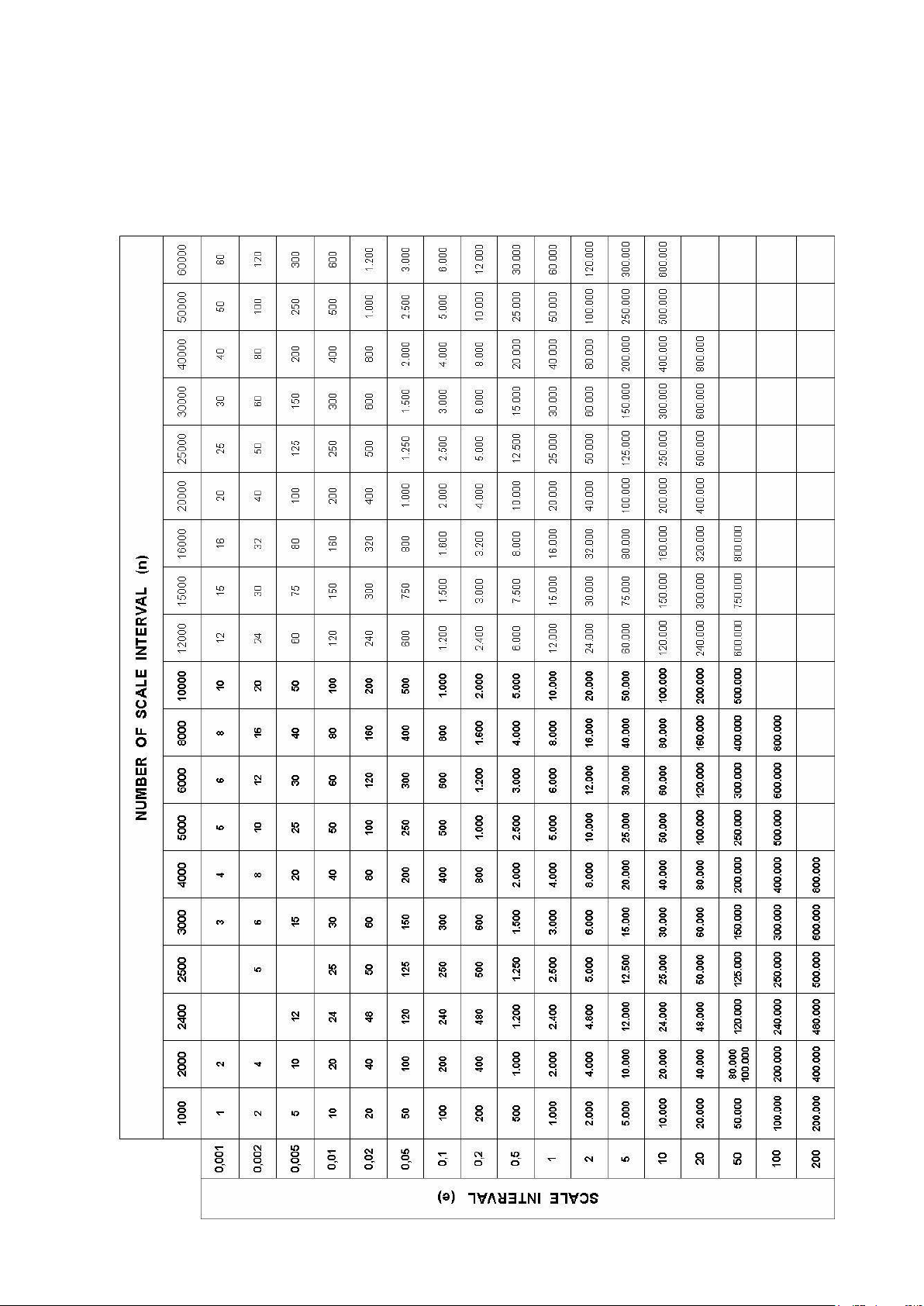
Page 79 of 82
15. CALIBRATION TABLE
n = Max Capacity / e recommended values are given in the table below. You can use this table to select your
Max and e values. Max value can be entered freely.
FT-10 Smart Process Indicator, Technical Manual, Rev. 1.0, January 2014
Page 81
Page 80 of 82
FREQUENTLY ASKED QUESTIONS
Question
:
My PC could not interface with FT-10. How can I check the com port?
Answer
:
− Connect the instrument to the PC and run Hyper Terminal.
− Check com ports as described in The Diagnostic Test section on Page 38.
Question
:
IndFace1X installation needs restart every time. How can I install it?
Answer
:
− Read and follow the installation notes in the installation directory.
− Update your computer (visit http://update.microsoft.com).
Question
:
IndFace1X could not connect to instrument. What can I do?
Answer
:
− Check the power, data cabling and LED status of the FT-10 instrument.
− Check PC port setting.
− Remove other connections. Re-energize the FT-10 instrument and then make connection.
Question
:
My PC doesn’t have any COM port. How can I connect instrument to my PC?
Answer
:
You can use RS-232 / USB converter for serial interfacing via USB port. And select com port
with Connection Settings menu.
Question
:
My PC have a COM port but I couldn’t see COM port in Connection Setting menu. How can I
solve that problem?
Answer
:
Another software may be connected to that COM port. Close all applications before running
IndFace1X.
Question
:
My PC could not interface with FT-10. How can I check the com ports?
Answer
:
Short circuit your com port RXD and TXD pins. Check if the sending data is received or not by
using any terminal software. You may test also FT-10 com ports as described in The Diagnostic
Tests section on Page 38 by short circuiting RXD and TXD terminals.
Question
:
I need very fast interfacing. What is the response delay time of FT -10?
Answer
:
FT-10 response delay is max. 4 milliseconds for weight data. Extremely fast interfacing.
Question
:
What is the external conversion rate of FT-10?
Answer
:
Only continuous data output rate might be called as an external conversion rate which is
depend on the baud rate and data length and up to 65
conversion/second.
Question
:
How can I check Ethernet connection?
Answer
:
− FT-10EN has a dummy web page. You can easily open web page with any browser installed
on any PC in network.
Question
:
EtherX is searching but it could not find any instrument over Local Network Area.
Answer
:
− Check the Exceptions tap in Windows firewall settings. EtherX should be marked.
− Check the firewall of Anti-virus program, If you have.
Question
:
I done crossover connection with FT-10 EN but EtherX could not find it.
Answer
:
− Check the Internet Protocol (TCP/IP) Properties in Local Area Connection of Windows. IP
address blocks and gateway address of FT-10 and PC should be the same in cross connection.
FT-10 Smart Process Indicator, Technical Manual, Rev. 1.0, January 2014
Page 82

Bemannsbruch 9
D-74909 Meckesheim
Deutschland / Germany
e-mail: [email protected]
http:// www.flintec.com
 Loading...