

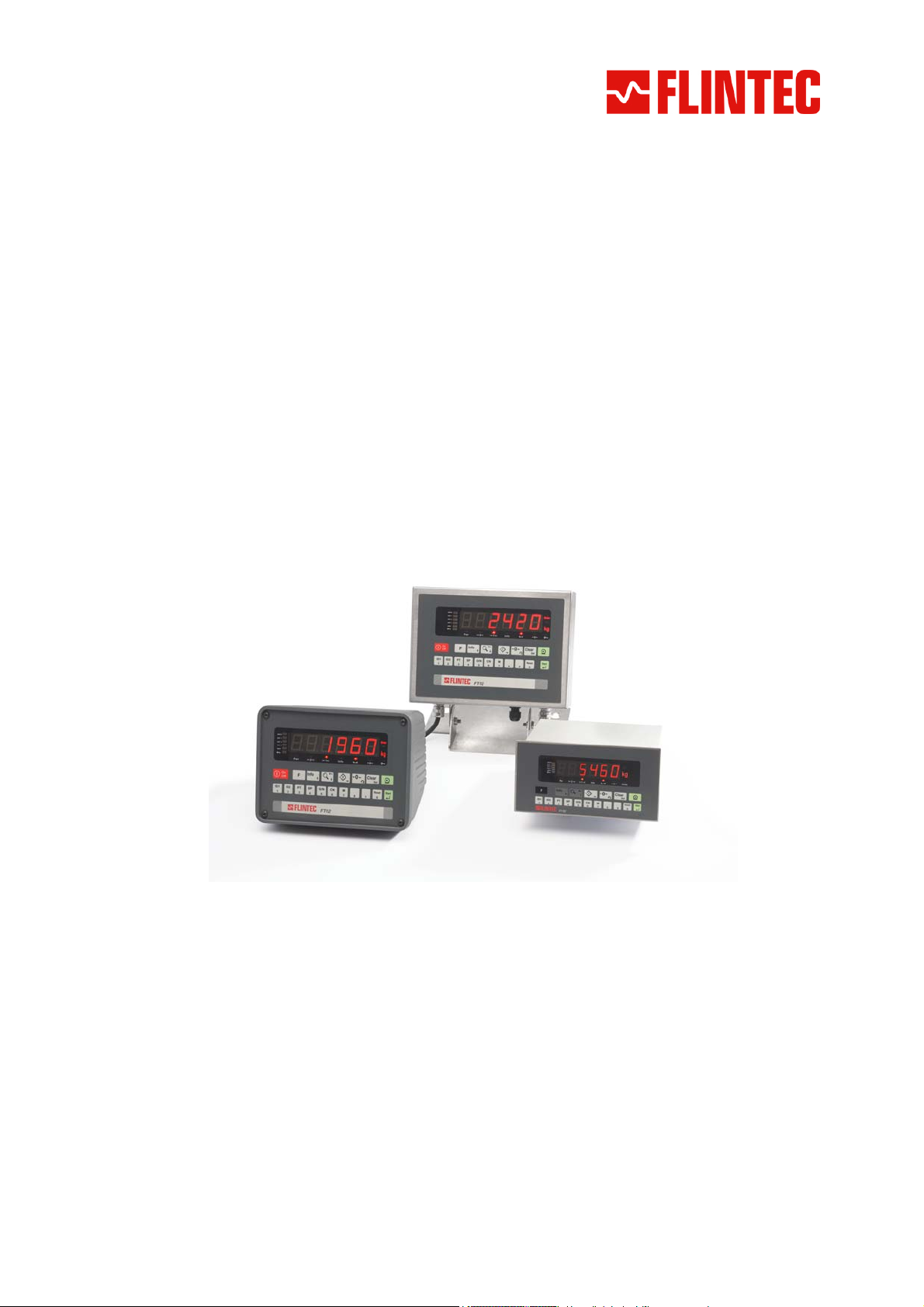
WEIGHT INDICATOR
FT-12
T
EECCHHNNIICCAALL
T
M
AANNUUAAL
M
L
For Firmware Version 2.07 and higher
Flintec GmbH
Bemannsbruch 9
74909 Meckesheim
GERMANY
www.flintec.com

Table of Contents:
1 Safety Instructions.........................................................................................................................................4
2 Declaration of Conformity.............................................................................................................................5
3 Overview..........................................................................................................................................................6
3.1 Key Features.............................................................................................................................................6
3.2 Available Options and Accessoires...........................................................................................................6
3.3 Technical Specifications............................................................................................................................7
3.4 Housing Dimensions .................................................................................................................................8
3.4.1 Desk Type Housing ...........................................................................................................................................8
3.4.2 Stainless Steel Housing ....................................................................................................................................8
3.4.3 Panel Type Housing ..........................................................................................................................................9
4 Installation and Commissioning.................................................................................................................10
4.1 Mechanical Installation............................................................................................................................10
4.1.1 Jumpers...........................................................................................................................................................10
4.2 Electrical Connections.............................................................................................................................10
4.2.1 Power Supply and Grounding..........................................................................................................................10
4.2.2 Standard Load Cell Connection.......................................................................................................................11
4.3 Commissioning........................................................................................................................................11
5 Front Panel and Keypad..............................................................................................................................12
5.1 Weight Display and Status LEDs ............................................................................................................12
5.2 Keypad ....................................................................................................................................................13
5.3 Key lock...................................................................................................................................................13
6 Setup and Calibration..................................................................................................................................14
6.1 Basics......................................................................................................................................................14
6.1.1 Basic Setup Keys on the Frontplate ................................................................................................................14
6.1.2 Entering the Setup and Calibration Menu........................................................................................................14
6.1.3 Exiting the Setup and Calibration Menu ..........................................................................................................14
6.2 Application Programmes.........................................................................................................................15
6.2.1 Basic Weighing................................................................................................................................................15
6.2.2 Check Weighing ..............................................................................................................................................15
6.2.3 Peak Hold........................................................................................................................................................15
6.2.4 Dynamic Weighing ..........................................................................................................................................16
6.2.5 Filling...............................................................................................................................................................16
6.2.6 Setup...............................................................................................................................................................16
6.3 Configuration Parameters .......................................................................................................................17
6.4 Scale Parameters....................................................................................................................................17
6.5 Scale Calibration .....................................................................................................................................19
7 Memory Operations......................................................................................................................................20
7.1 ID Memory...............................................................................................................................................20
7.2 Preset Tare Memory ...............................................................................................................................20
7.3 Setpoint Memory .....................................................................................................................................20
8 Alibi Memory and Legal Metrological Records.........................................................................................21
9 Communication ............................................................................................................................................22
9.1 Overview about Communication .............................................................................................................22
9.2 Serial Interface and Printer .....................................................................................................................22
9.2.1 Standard Serial Interface Connector (RS232C) ..............................................................................................22
9.2.2 Optional Serial Interface Connector (RS232C, RS485, 20 mA TTY)...............................................................22
9.2.3 Continuous Output Mode ................................................................................................................................23
9.2.4 Host Mode.......................................................................................................................................................23
9.2.5 Print Mode.......................................................................................................................................................23
9.2.6 Setup...............................................................................................................................................................24
FT-12 Technical Manual, Rev. 1.35 November 2010
Page 2 of 44

9.3
Ethernet Option .......................................................................................................................................27
9.3.1 Electrical Connections.....................................................................................................................................27
9.3.2 Setup...............................................................................................................................................................27
9.3.3 Data Structure .................................................................................................................................................29
10 Other I/O Options......................................................................................................................................30
10.1 Analogue Output Option ......................................................................................................................30
10.1.1 Electrical Connections .....................................................................................................................................30
10.1.2 Setup ...............................................................................................................................................................30
10.2 Digital I/O Option .................................................................................................................................31
10.2.1 Electrical Connections .....................................................................................................................................31
10.2.2 Setup ...............................................................................................................................................................31
10.2.3 Entering Setpoints ...........................................................................................................................................32
10.3 Binary Output Option ...........................................................................................................................32
11 Diagnostics ...............................................................................................................................................33
Appendix 1: Setup and Calibration Menus......................................................................................................34
Appendix 2: Continues Output Mode Data Structure.....................................................................................35
Appendix 3: Host Mode Data Structure............................................................................................................36
Appendix 4: Modbus RTU Data Structure........................................................................................................39
Appendix 5: Error Table.....................................................................................................................................42
Appendix 6: Parameter’s Default Table............................................................................................................43
Appendix 7: Calibration Table...........................................................................................................................44
FT-12 Technical Manual, Rev. 1.35 November 2010
Page 3 of 44
RIGHTS AND LIABILITIES
All rights reserved.
No part of this publication may be reproduced, stored in a retrieval system, or transmitted in any form or by any
means, mechanical, photocopying, recording, or otherwise, without the prior written permission of Flintec GmbH
No patent liability is assumed with respect to the use of the information contained herein. While every
precaution has been taken in the preparation of this book, FLINTEC assumes no responsibility for errors or
omissions. Neither is any liability assumed for damages resulting from the use of the information contained
herein.
The information herein is believed to be both accurate and reliable. FLINTEC, however, would be obliged to be
informed if any errors occur. FLINTEC cannot accept any liability for direct or indirect damages resulting from
the use of this manual.
FLINTEC reserves the right to revise this manual and alter its content without notification at any time.
Neither FLINTEC nor its affiliates shall be liable to the purchaser of this product or third parties for damages,
losses, costs, or expenses incurred by purchaser or third parties as a result of: accident, misuse, or abuse of
this product or unauthorized modifications, repairs, or alterations to this product, or failure to strictly comply with
FLINTEC operating and maintenance instructions.
FLINTEC shall not be liable against any damages or problems arising from the use of any options or any
consumable products other than those designated as Original FLINTEC Products.
NOTICE: The contents of this manual are subject to change without notice.
Copyright © 2008 – 2010 by Flintec GmbH, 74909 Meckesheim, Bemannsbruch 9, Germany
1 SAFETY INSTRUCTIONS
CAUTION READ this manual BEFORE operating or servicing this equipment. FOLLOW
these instructions carefully. SAVE this manual for future reference. DO NOT allow untrained
personnel to operate, clean, inspect, maintain, service, or tamper with this equipment.
ALWAYS DISCONNECT this equipment from the power source before cleaning or performing
maintenance. CALL FLINTEC ENGINEERING for parts, information, and service.
WARNING ONLY PERMIT QUALIFIED PERSONNEL TO SERVICE THIS EQUIPMENT.
EXERCISE CARE WHEN MAKING CHECKS, TESTS AND ADJUSTMENTS THAT MUST BE
MADE WITH POWER ON. FAILING TO OBSERVE THESE PRECAUTIONS CAN RESULT
IN BODILY HARM.
WARNING FOR CONTINUED PROTECTION AGAINST SHOCK HAZARD CONNECT TO
PROPERLY GROUNDED OUTLET ONLY. DO NOT REMOVE THE GROUND PRONG.
WARNING DISCONNECT ALL POWER TO THIS UNIT BEFORE REMOVING THE FUSE
OR SERVICING.
WARNING BEFORE CONNECTING/DISCONNECTING ANY INTERNAL ELECTRONIC
COMPONENTS OR INTERCONNECTING WIRING BETWEEN ELECTRONIC EQUIPMENT
ALWAYS REMOVE POWER AND WAIT AT LEAST THIRTY (30) SECONDS BEFORE ANY
CONNECTIONS OR DISCONNECTIONS ARE MADE. FAILURE TO OBSERVE THESE
PRECAUTIONS COULD RESULT IN DAMAGE TO OR DESTRUCTION OF THE
EQUIPMENT OR BODILY HARM.
CAUTION OBSERVE PRECAUTIONS FOR HANDLING ELECTROSTATIC SENSITIVE
DEVICES.
FT-12 Technical Manual, Rev. 1.35 November 2010
Page 4 of 44

2 DECLARATION OF CONFORMITY
EG-Konformitätserklärung
0
Monat/Jahr: month/year: 07/2010
Hersteller: Manufacturer: Flintec GmbH
Anschrift: Address:
Produktbezeichnung: Product name: FT-12 Wäge-Indikator / FT-12 Weight Indicator
Das bezeichnete Produkt stimmt mit folgenden Vorschriften der Europäischen Richtlinien überein:
This product confirms with the following re gula tions o f the Directive s of the European Community
Richtlinie 2004/108/EG des Europäischen
Parlaments und des Rates vom 15. Dezember 2004
zur Angleichung der Rechtsvorschriften der
Mitgliedstaaten über die elektromagnetische
Verträglichkeit und zur Aufhebung der Richtlinie
89/336/EWG
Richtlinie 2006/95/EG Niederspannungs-Richtlinie
EC-Declaration of Conformity
Bemannsbruch 9
D-74909 Meckesheim
Deutschland / Germany
Directive 2004/108/EC of the European Parliament and of the
Council of 15th December 2004 on the approximation of the
laws of the Member States relating to electromagnetic
compatibility and repealing Directive 89/336/EEC
Directive 2006/95/EC Low Voltage Directive
Die Absicherung aller produktspezifischen
Qualitätsmerkmale erfolgt auf Basis eines zertifizierten
Qualitätsmanagement-Systems nach DIN ISO 9001.
Diese Erklärung bescheinigt die Übereinstimmung mit
den genannten Richtlinien, beinhaltet jedoch keine
Zusicherung von Eigenschaften.
Folgende Normen werden zum Nachweis der Übereinstimmung mit den Richtlinien eingehalten:
As a proof of conformity with the directives following standards are fulfilled:
EN 61326-1
EN 60950-1
Elektrische Mess-, Steuer-, Regel- und Laborgeräte - EMV-Anforderungen - Teil 1: Allgemeine
Anforderungen (IEC 61326-1:2005)
Electrical equipment for measurement, control and laboratory use - EMC requirements - Part 1: General
requirements (IEC 61326-1:2005)
Einrichtungen der Informationstechnik - Sicherheit - Teil 1: Allgemeine Anforderungen (IEC 609501:2005, modifiziert);
Information technology equipment - Safety - Part 1: General requirements (IEC 60950-1:2005 modified)
All product-related features are assured by a quality
system in accordance with ISO 9001.
This declaration certifies the conformity with the listed
directives, but it is no promise of characteristics.
FT-12 Technical Manual, Rev. 1.35 November 2010
Page 5 of 44

3 OVERVIEW
The type FT-12 weight indicator is an economic and powerful state-of-the-art instrument. Its application covers
any type of standard weighing process including dynamic weighing, check weighing and filling.
The accurate and versatile instrument is available in different housings, meeting the industries demand for
various environmental conditions.
FT-12 is approved by Weights & Measures Authorities for use in Accuracy Class III applications with up to 10
000 intervals according to OIML R76. It has a large 6 digit LED weight display (red, 20 mm or 14 mm high) with
weight status information. With a variety of interface options the FT-12 weight indicator is the perfect fit to
weighing systems and process control systems.
3.1 Key Features
EU Type approved for 10 000 intervals
Single or dual range
Approved sensitivity 0.4 mV/e
High internal resolution up to 8 000 000 counts
Display resolution up to 60 000 counts
Maximum conversion rate of 100/s
Adaptive digital filter for fast and stable reading
High resolution display mode
Up to 6 load cells (350 ) or 18 load cells (1100 )
Realtime clock
Standard Serial interface RS232C
Integrated AC power supply
Zeroing with one button & Taring with one button
Auto-zero tracking and auto-zero at power-up
99 preset tare values & auto tare clear option
Motion detection
Printout in different formats incl. header and footer
Totalizing and printing of consequential weighing results
Setpoint monitoring (3 setpoints, digital I/O required)
9 set point groups with 3 setpoints each
5 standard application modes incl. check weighing, dynamic weighing, filling, and peak hold
Key lock option to prevent unauthorized access
3.2 Available Options and Accessoires
Alibi memory for up to 149 764 weighing results
Additional serial interface RS232C
Additional serial interface RS232C / 20 mA TTY CL* / RS485 (* not for stainless steel housing)
Modbus RTU
Ethernet TCP/IP and Modbus RTU over Ethernet
Analogue output 0 – 10 V and 4 – 20 mA
Binary data output (17-bit code)
Digital inputs / outputs
12 V DC (12…17 V DC) power inlet
24 V DC (20…27 V DC) power inlet
Rechargeable battery (for 230 V AC version only)
Flintec IndFace Software
FT-12 Technical Manual, Rev. 1.35 November 2010
Page 6 of 44
3.3 Technical Specifications
Accuracy
Accuracy class: III
EU Type approved: 10 000 intervals (single range); 2x 6 000 intervals (dual range)
Display and Keyboard
Display: 6 digits, 7 segments, LED red, 20 mm high (Panel type 14 mm high)
Display update rate: 250 ms
Keyboard: 18-keys; membran with tactile feedback
A/D Converter
A/D converter type: 24 bit Delta-Sigma ratiometric with integral analog and digital filters
Conversion rate: Max. 100 measurement values per second
Input sensitivity: 0.4 V/e (approved), 0.1 V/d (non approved)
Analogue input range: 0 to 20 mV
Internal resolution: Up to 8 000 000 counts
Display resolution: Up to 60 000 counts
Scale Calibration and Functions
Calibration: Calibration is performed by application weights
Corner adjustment: Only externally
Digital filter: In 10 step adjustable
Application modes: Basic weighing, filling, check weighing, dynamic weighing and peak hold
Weighing functions: Tare, zero, auto zero tracking, motion detection, auto zero at power up
Programmable setpoints: 9 groups with 3 setpoints each (needs digital I/O option)
Alibi memory: Optionally available: 74 880 records or 149 760 records
Linearity:
Load cells
Excitation:
Number of load cells:
Connection: 4- or 6-wire technique. Cable length 274 m/mm² for 6-wire connection
Communication:
Continuous mode update rate: 100 ms
Option board update rate: 40 ms
Power supply:
AC Power supply 200…240 V AC, 50/60 Hz
DC Power supply optionally 12…17 V DC, max. 12 VA or optionally 20…27 V DC, max. 12 VA
Battery runtime:
Battery charging time: 6 h
Environment and Enclosure
Operation temperature: -10 °C to +40 °C legal for trade; max. 85% RH, non-condensing
Enclosure
Up to 6 load cells (350 ) or 18 load cells (1 100 ) connected in parallel
Standard serial interface RS232C; 1 200 to 57 600 baud; programmable
Within 0.0015% FS, 2 ppm/°C
5 V DC at 58...1200 max. 100 mA
5 h (with 93 LC) to 7 h (with 410 LC)
Aluminium cast desk type (IP30) or
panel type (front panel IP65) or
stainless steel (IP65)
FT-12 Technical Manual, Rev. 1.35 November 2010
Page 7 of 44
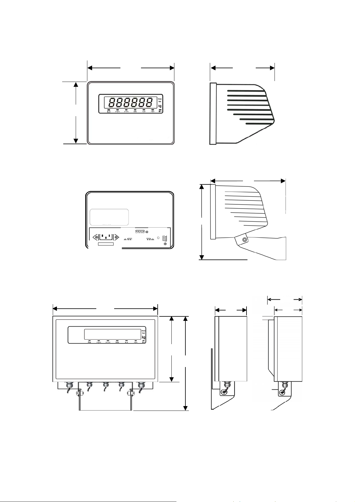
3.4 Housing Dimensions
3.4.1 Desk Type Housing
140
Desk type front view Desk type side view
RS232
OPTIO
S/N
Desk type rear view Dimensions of Desk type housing with wall mount kit
155195
187
179
LOAD CELL
3.4.2 Stainless Steel Housing
220
220
220
Stainless steel housing front view Stainless steel housing side view
160
160
160
70
70
15
15
15
230
230
230
100 mm deep with big backplane option
100
100
100
70
70
70
FT-12 Technical Manual, Rev. 1.35 November 2010
Page 8 of 44
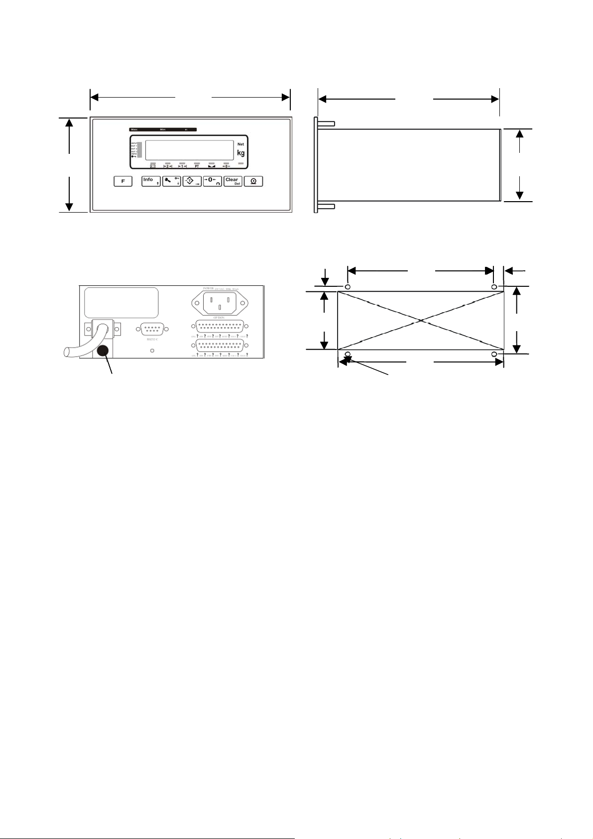
3.4.3 Panel Type Housing
90
Panel type front view Panel type side view
174
5,5
5,5
5,5
69
69
69
175
144
144
144
80
80
80
68
9
9
9
164
164
164
Sticker
Sticker
5, mounting with 4x M4
Panel type rear view The hole dimensions for mounting on a panel
FT-12 Technical Manual, Rev. 1.35 November 2010
Page 9 of 44
4 INST ALLATION AND COMMISSIONING
PRECAUTION: Please read this manual carefully before energizing the indicator. Perform the commissioning
operation according the procedure given here. Use trained personnel for cleaning, commissioning, checking and
service of the indicator. The interference of untrained personnel may cause some unwanted damages or injures.
Note: In this manual the term “Digital Load Cell“ will be refered to “DLC“.
4.1 Mechanical Installation
First of all please determine the place where your indicator can operate safely. This place should be clean, not
getting direct sun light if possible, with a temperature between -10 ºC and +40 ºC, humidity not exceeding 85%
non-condensing. Take care to the housing dimensions and the suggested panel hole dimensions given in
chapter 3.5. All the cables should be installed safely to avoid mechanical damages.
To avoid electrical noise protect your indicator which has very low input signal level from the equipment that
produces electrical noise, especially in panel mounting.
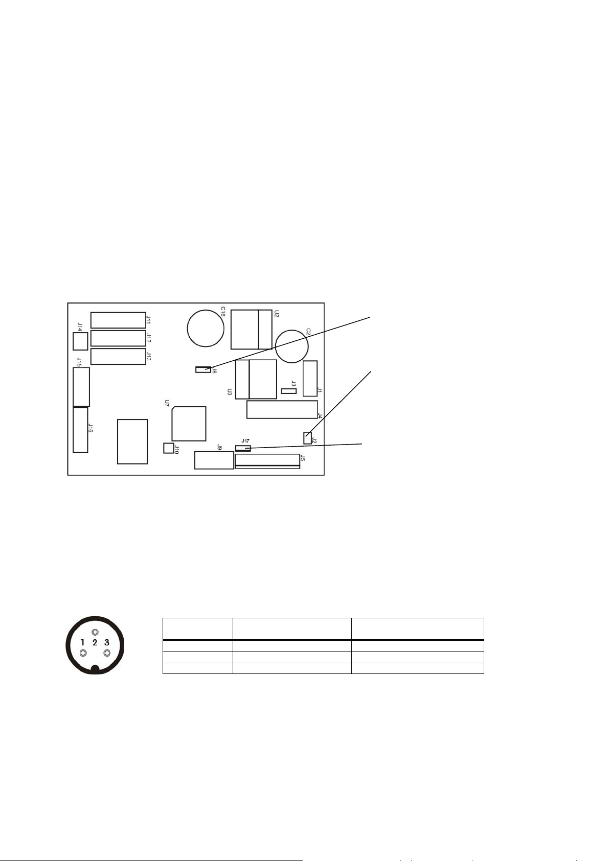
4.1.1 Jumpers
There are three jumpers on the instrument’s main board/weighing board for calibration and for switching on/off.
To change the position of this jumpers, open the housing and perform the necessary changes before energizing
the indicator.
Figure 4.1 FT-12 Main board
J8 On/Off Switch
(always short circuit at the Panel type)
J2 Calibration
(short circuit for calibration)
J17 short circuit for on/off key function
4.2 Electrical Connections
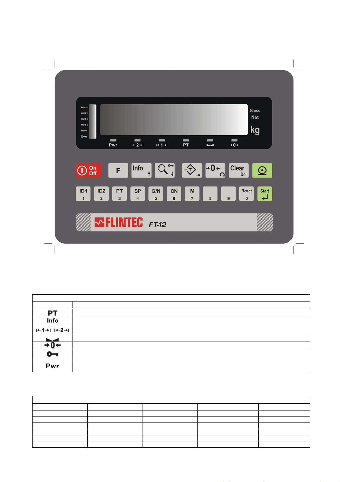
4.2.1 Power Supply and Grounding
FT-12 is available with 230 V AC power supply or 24 V DC or 12 V DC power inlet. The 230 V AC indicators are
supplied with a power cable; the DC indicators are supplied with a special connector for the power inlet.
Prepare your power voltage according to your instrument’s power inlet. The DC connector pin configuration can
be found in Figure 4.2 below.
Definition
12 V / 24 V 1 3
0 V 2 2
Housing Gnd 3 1
Desk / Panel
The quality of the instrument’s ground will determine the accuracy and the safety of your indicator. A poor
ground can result in an unsafe condition if an electrical short cuircuit happens. A good ground connection is
needed to minimize extraneous electrical noise pulses. It is important that the instrument does not share power
lines with noise-generating equipment such as heavy load switching, motor control equipments, inductive loads,
etc. If the condition of the power line in the plant is bad, prepare a special power line and grounding.
If you have to service the indicator, turn off the power and wait at least for 30 seconds before interfering.
All connectors are at the rear side of the housings of desk and panel types. The stainless steel housings must
be opened to make the required connections. These connections must be done as described below.
Figure 4.2 The pin layout of the DC connector
for desk and panel type
Pin no.
for stainless steel housing
Pin no.
FT-12 Technical Manual, Rev. 1.35 November 2010
Page 10 of 44

4.2.2 Standard Load Cell Connection
The load cell wiring should be made carefully before energizing to avoid damages to the weight indicator and
the load cells. The input resistance of the load cells that you want to connect should be more than 58 .
The sense pins of the instrument should be connected. In 4-wire installations the sense and excitation pins with
the same polarity should be short circuited at the connector side.
6-wire Load Cell
Connection
+ Excitation + Excitation 1 1
+ Sense + Excitation 2 2
Shield Shield 3 4
- Sense - Excitation 4 6
- Excitation - Excitation 5 7
+ Signal + Signal 7 3
- Signal - Signal 8 5
Shield Shield Connector body 4
4-wire Load Cell
Connection
Pin no. for desk type & panel
type (D-Sub, 9-pin, female)
Pin no. for Stainless steel
housing (J12 connector)
4.3 Commissioning
After making the required installations and connections to your indicator, turn the power on and perform
following steps:
Get familiar with the instrument’s setup mode (see chapter 6.1)
Set up the application mode (see chapter 6.2)*
Define the configuration parameters (see chapter 6.3)*
Define the scale parameters (see chapter 6.4)
Calibrate the scale (see chapter 6.5)
* Note: Most of the parameters can be skipped for later setup. Please take care for the parameters which may
be locked by the J2 calibration jumper in legal for trade applications (see Appendix 1: Setup and Calibration
Menu of the instrument).
If you want to use the Flintec IndFace Software for FT-12 then you have to set up the instrument’s standard
serial interface to host mode (see chapter 9.2) before you adjust all the configuration parameters.
After checking the performance of your weighing instrument you can begin to use the indicator.
If there are peripheral connections, first you should turn the power off; make the peripheral connections, perform
the required safety checks and energize the indicator. Then set the related parameters and check if the
peripheral devices are operating properly.
If required perform following additional steps:
Set up the memory functions (see chapter 7)
Set up the serial interfaces (see chapter 9.2)
Printer setup (see chapter 9.2)
Set up other optional inputs and outputs (see chapter 9.3 and 10)
FT-12 Technical Manual, Rev. 1.35 November 2010
Page 11 of 44
5 FRONT PANEL AND KEYPAD
5.1 Weight Display and Status LEDs
Figure 5.1 Front panel view of FT-12
The weight display of FT-12 is a 6 digit LED with 14 mm or 20 mm height.
At the right side of the display there are 3 status LEDs for indicating “Gross”, “Net” and the standard unit “kg”.
Below the weight display there are 6 status LEDs related to the weighing process:
Status LEDs related to the weighing process
LED Meaning
Preset tare: Indicator works with a preset tare
Info: The instrument displays information different from the weight
Range: With multi range scales these LED indicates the current operating range. For single range
scales only the first range LED is lit.
Stable: The weight value on the display is stable
Center of zero: The weight is in the center of zero (see param. [203] in chap.6.3)
Key lock: is active
Power: This LED will flash in case of supply voltage decrease. If the voltage decreases too much the
indicator will automatically shut off.
At the left side of the weight display there is a group of 6 status LEDs that have different meanings according to
the current application programme (for details refer to the relevant section in chapter 6.2.):
Status LEDs related to the application programme
Basic Weighing
INPUT W + + Ready INPUT Start
OUT 1 W + In Process OUT 1 Ready
OUT 2 OK EOP OUT 2 Coarse
OUT 3 W - Error OUT 3 Fine
INFO W - - INFO INFO EOB
Key Lock Key Lock Key Lock Key Lock Key Lock
Check Weighing Peak Hold Dynamic Weighing Filling
FT-12 Technical Manual, Rev. 1.35 November 2010
Page 12 of 44
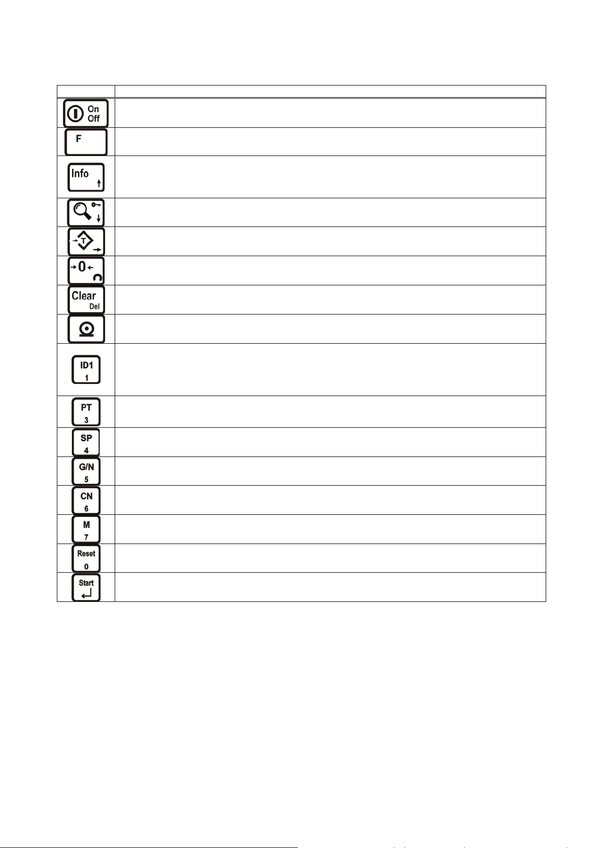
5.2 Keypad
The meaning of the front panel keys and the key functions are:
FT-12 Meaning
Power On/Off: This key is used for turning the instrument on or off. To switch off the key must be
pressed and hold at least for 2 seconds. There is no On/Off key on panel type housings.
Function : This key is used in combination with other keys to enter any function or to quit without saving.
Info: This key is being used to view Total and CN information. To toggle between these infos you have to
press this key repeatedly and finally you will return to weighing mode again. To clear the total weight, you
have to press the <Clear> key while the total value is seen on the display. [All C ] will appear on the
display. You can confirm the deletion by pressing <Enter> or cancel by pressing the <F> key.
High Resolution: By pressing this key the weight value will be shown with a higher resolution for a short
period.
Manual Tare: Pressing this key tares the scale and gets into the Net mode.
Manual Zero: In Gross mode, if the scale doesn’t show zero while there is no load on the pan, you can
zero the scale by pressing this key.
Clear: Pressing this key clears the tare and the scale and returns to Gross mode.
Print: By pressing this key weight data and other information depending on the instrument setup are sent
to a printer or a PC via serial port.
ID1, ID2 : These keys are used for entering new ID codes or with <F> key for calling IDs from the
memory. To enter a new ID, you have to press one of the ID keys (ID1 or ID2), then enter the value via
numerical keypad and confirm with <Enter>. You can cancel the ID entry and return to the weighing mode
by pressing the <F> key.
Numerical Keypads: These keys are used for entering numerical values in setup mode.
Preset Tare: After pressing this key you can manually enter a tare value via numerical key pad. After
confirming with <Enter> key the indicator tares the scale with this value. If you do not want to change this
value, quit with <F> key.
Setpoint: These keys are being used to view or to enter setpoint values.
Gross/Net: This key is being used to see the gross weight value without clearing the tare value while
working in Net mode.
Label No: After pressing this key, first [CN ] message appears on the display then you can see the CN
no. By pressing the <F> key or after a while automatically it returns to weighing mode.
Memory: This key is used for data entry to ID, PT and setpoint memories.
Numerische Tasten: Eingabe von numerischen Parameterwerten bei der Konfiguration.
Reset: This key is used to reset the process in Filling, Peak hold and Dynamic mode.
Enter: This key is used for confirming an entered value and to get to the next parameter in setup mode.
This key is also used to start the process in Filling, Peak hold and Dynamic modes.
5.3 Key lock
The instrument has the capability to lock the keys to avoid unauthorized person’s interference. You can activate
or deactivate this function by pressing the <F> and <Key Lock> keys sequentially. The LED with the key sign
(below the display) indicates the keys are locked.
FT-12 Technical Manual, Rev. 1.35 November 2010
Page 13 of 44

6 SETUP AND CALIBRATION
6.1 Basics
6.1.1 Basic Setup Keys on the Frontplate
The symbols located on the lower right corner of each key indicate the function of the keys in the setup menu.
The basic meanings of these keys are given in the table below.
Enter
Exit
without
saving
Stepping
forwards to
the next
parameter
Stepping
backwards to
the previous
parameter
Changing
the digit
Entering
the
parameter
value
Changing the
value or
increasing the
flashing digit
Clear
(delete)
If you use a PC the Flintec IndFace software can be used for the setup and the calibration of FT-12.
6.1.2 Entering the Setup and Calibration Menu
To enter the Setup and Calibration Menu: Press <F> and <Info> keys sequentially
First [FunC ] and then [PASSWr ] prompts will be displayed sequentially.
Here you can enter the parameter block by using:
the service password: Press <Zero> and <Info> and <Enter>
or the operator password: Press <Tare> and <Enter>
The calibration jumper (see chapter 4.1) should be short circuit to change the legal metrological parameters in
the service mode (there is black box on the top right corner of the grey coloured boxes in the calibration menu
flowcharts, see Appendix 1).
The Setup and Calibration menu consists of main blocks which are displayed as [X-- ] and sub-blocks.
By using <> and <> keys you can reach previous or next main blocks. After reaching the desired main block
you can get in by pressing the <Enter> key. As you enter the block you will reach the first sub-block in that main
block. The sub-block address will be seen on the display as [X0- ].
You can also search between the sub-blocks by using <> and <> keys and reach the first parameter of the
displayed sub-block by pressing the <Enter> key. The number of the parameter is displayed as [XY0 ]. Again
you can search between parameters by <> and <> keys.
FT-12 has numerical keys for entering parameter values.
6.1.3 Exiting the Setup and Calibration Menu
Whatever parameter block you are in – if you press the <F> key, you will get out of the active sub-block and
reach the next sub-block. If you press the <F> key again you will get out of the active block and reach the next
main block. If you press the <F> key once again, the [SAvE ] message appears on the display.
Here you can press
the <Enter> key to save the changes into the memory or
you can press the <Tare> key to store the changes temporarily until the power goes off or
you can press the <F> key to abort any changes.
The [Waıt] message will be displayed for a few seconds and afterwards the weighing mode will restart
automatically. Especially for legal metrological usage, please don’t forget to turn the power off and remove the
calibration jumper before you start the operation.
FT-12 Technical Manual, Rev. 1.35 November 2010
Page 14 of 44

6.2 Application Programmes
T1
T2
Besides basic weighing the FT-12 indicator can be used in different common applications such as check
weighing (over/under), peak hold, dynamic weighing (animal weighing) and automatic filling.
The status LEDs located at the left side of the display and the digital I/O have different meanings according to
the selected application mode. The meanings and the structure of the digital I/O are given in chapter 10.
6.2.1 Basic Weighing
This is the convenient application mode for general weighing applications. The FT-12 weighing indicator can be
used in both single range and dual range scales. In the basic weighing mode the weight data can be printed on
a label, together with header and footer.
FT-12 has also the capability of totalizing sequential weights, 99 preset tare memories, 99 alphanumerical ID
memories and 9 groups of setpoint memory – each setpoint group has 3 outputs. If an alphanumeric header of
an ID and/or an alphanumeric ID data has been downloaded to FT-12, the alphanumeric name of this ID can
also be printed together with an alphanumeric ID header. Please see the “Memory Operations” in chapter 7 and
the print examples in chapter 9.2.
6.2.2 Check Weighing
This application mode is used to compare the weight of the load placed on the pan with the predefined target
plus/minus tolerance values. FT-12 can store 9 set point groups, each includes three different set points. In this
way the target and tolerance values for 9 different items can be stored within FT-12 and the selection of these
items can simply be done by keys.
--
WT-T2
The nominal target value and tolerance data will be entered as given below:
WT (Target weight) = SP1 Tolerance T1 = SP2 Tolerance T2 = SP3
If only one tolerance is needed, so T1 is the right choice (T2 has to be adjusted to a high value respective it has
to be ignored).
In the check weighing mode the weight value must be above a threshold value (parameter [101]) for activating
the outputs. When the weight exceeds the threshold value, the weight monitoring process starts automatically.
The keys are locked and the weighing result is annunciated to the status LEDs and/or digital outputs.
Status LED G < WT-T2 WT-T2 < G < WT-T1 G = WT+/-T1= OK WT+T1 < G < WT+T2 G > WT+T2
Input On
Out1 On
Out2 On
Out3 On
Info On
-
WT-T1
T2
T1
WT
WT+T1
+
WT+T2
++
6.2.3 Peak Hold
The peak hold mode is generally used in compression, tension and tearing test applications. The force is
monitored and the maximum value is hold on the display. First the threshold value (parameter [101]), the ending
rate (parameter [102]) and the alarm value (parameter [104]) should be defined in the setup mode (see chapter
6.3.6). The peak hold process starts by pressing the <Start> key. The output no.2 activates which means the
peak hold process is running. Until the force reaches the threshold value (parameter [101]), the message [LoAd]
and the applied force are shown on the display sequentially. In this period the force is not monitored to hold the
peak value. After reaching the threshold value the [LoAd ] message will disappear, the force is now being
monitored and the maximum force value is displayed. If the force decreases more than the rate entered as the
ending rate (parameter [102]) the peak hold process ends. Output no.2 deactivates again. Now output no. 3
activates, which means the peak hold process has finalized. The [PEAK ] message and the peak value are
shown on the display continuously. If the auto print function has been activated (parameter [046] = “1”) the test
result will be automatically printed. The <Reset> key can be used to stop the process. If the force exceeds the
value entered as alarm value (parameter [104]) the process automatically stops and the [ ovEr] message
FT-12 Technical Manual, Rev. 1.35 November 2010
Page 15 of 44

appears on the display. An alarm condition can be stopped by pressing the <Reset> key. Starting or resetting
g
g
the peak hold process can be also be done by a digital input.
6.2.4 Dynamic Weighing
The dynamic weighing mode generally is used for weighing unstable objects like animals. First the threshold
value (parameter [101]) and the time parameter (parameter [103]) should be defined in the setup mode (see
chapter 6.2.6).
If the weight value is above the threshold value, dynamic weighing will be started by pressing the <Start> key or
applying a digital start input. The [------] message is shown on the display. After the pre-defined time delay
(minimum 5 s) the [End ] message and then the weight value are shown on the display. If the auto print
function has been activated (parameter [046] = “1”) the weighing result will be automatically printed. The
dynamic weighing process can be stopped by pressing the <Reset> key or by activating the digital input no.3.
6.2.5 Filling
The filling mode is used for automatic filling applications in gross or in net. FT-12 can store 9 setpoint groups
with three different setpoints for each. By this the target weights, the coarse feeding values and the fine feeding
values for 9 different items can be stored within FT-12 and the selection of any items is simply done by keys.
Target weight, coarse and the fine feeding values will be entered as setpoints as shown below.
SP1 = Target value
SP2 = Fine feeding value If the actual weight value gets closer to the target value than the value defined
SP3 = Preact value If the actual weight value gets closer to the target value than the value defined
The threshold value (parameter [101]) is used for the tare control. If the weight is higher than this threshold
value the filling process starts by pressing the <Start> key or by applying a digital start input. If available and
after taring the coarse feeding output (output no.1) and the fine feeding output (output no.2) activate. After
reaching the fine feeding value (SP1-SP2) the coarse feeding output (output no.1) deactivates. After reaching
the preact value (SP1-SP3) the fine feeding output (output no.2) deactivates. Now the “End Of Filling” output
(output no.3) activates which indicates the end of the filling process. If the auto print function has been enabled
(parameter [046] = “1”) the weighing result will be automatically printed. After unloading the scale the “End Of
Filling” output (output no.3) deactivates again and the indicator becomes ready for the next filling cycle.
Coarse Feedin
SP1-SP2
here, the filling turns into fine feeding.
here, the filling ends.
Fine Feedin
SP2
SP1-SP3
Target weight
Weight
SP3
6.2.6 Setup
[10-] Application
In this sub-block you can select the application mode and enter the parameters related to the selected mode.
[100 X] Mode
0 : Simple Weighing (factory default setting) 1 : Check Weighing
2 : Peak Hold 3 : Dynamic Mode 4 : Filling
[101 ] Minimum Weight
[XXXXXX] Numerical entry. The minimum weight value which must be exceeded to start the process in peak
hold, check weighing, dynamic mode and filling mode. Factory default setting = 100 kg
[102 XX] Ending Rate
X = 0…99% This parameter is used in peak hold mode. The peak value will be captured when the weight
value decreases more than the percentage entered here. Default setting = 50%
[103 X.X] Period
X = 5.0…9.9 s This parameter is used in the dynamic mode for weighing of unstable weights. The evaluation will
be performed after the defined time span has elapsed. Default setting = 9.9 s
[104 ] Alarm
[ XXXXXX] Numerical limit value for creating an alarm. Factory default setting = 0 (disabled)
FT-12 Technical Manual, Rev. 1.35 November 2010
Page 16 of 44

[105 ] Filling Type (only for filling application)
0 : Gross filling (factory default setting) 1 : Net filling
6.3 Configuration Parameters
[1--] Configuration Block
[11-] Start Up
[111 X] Auto Power Off
0 : Auto power off disabled (default) 1 : Power off after 3 minutes of stability or no key function
2 : Power off after 10 minutes of stability or no key function
[112 X] Store Tare at Power Off
0 : Disabled (factory default) 1 : Enabled
[113 X] Auto Clear Tare
0 : Disabled (factory default) 1 : The scale returns to gross mode after unloading
[114 X] Buzzer
0 : Disabled (factory default) 1 : The Buzzer will be actived if any key is pressed OR
any error message occurred OR any alarm is active.
[12-] Filter
In this block the proper filter values according to the operating conditions can be entered. One of the most
important features of the indicator is viewing the filter characteristics on the display and with the help of this
option, you can select the most suitable filter without leaving the setup mode.
[120 X ] Filter
The filter value can be set from 0 to 9 (The minimum value of the filter is at least 7 in normal weighing applications).
When you enter this parameter and press the <Enter> key while [120 X] is shown on the display, the weight
variation can be seen on the display. The value of the filter can be changed by using the <> and <> keys and the
weight variation for each value is shown on the display. After finalising the filter selection you can go to the next step
by pressing the <F> key.
[14-] Entries
In this block you can enter the initial CN (consecutive number).
[140 ] Date
[DD.MM.YY] First press the <Tare> key for the date entry, then enter the new date via numerical keys and
save by pressing <Enter>.
[141 ] Time
[ HH.MM] First press the <Tare> key for the time entry, then enter the new date via numerical keys and
save by pressing <Enter>.
[142 ] Label No. (CN)
[ XXXXXX ] The desired value is entered via <Tare> and <Zero> keys and saved by pressing <Enter>. If the
number exceeds 65 535 it will automatically restart at 1.
6.4 Scale Parameters
[2--] Scale Block
The parameters related to the weighing operation are located here.
[20-] Set Up
[200 X] Approved
0 = No 1 = Yes
[201 X] Increased Indication (10x)
0 = By pressing key 1 = Always increased indication
FT-12 Technical Manual, Rev. 1.35 November 2010
Page 17 of 44

[202 X] Power On Zero
This parameter setting controls if after power-on the scale will get automatically zeroed if the weight is in the
percentage of the zeroing range. If the weight is not in the zeroing range the display will show [E E E ] message until
you press the <Enter>.
0 = disable 1 = ± 2% 2 = ± 10%
[203 X] Zeroing Range
0 = disable 1 = ± 2% 2 = ± 20%
[204 X] Auto Zero Tracking
AZT automatically re-adjusts the scale to zero for compensating defined small deviations around the centre of zero.
0 = disable 1 = ± 0,5e 2 = ± 1e 3 = ± 3e
[205 X] Tare
0 = Disabled 1 = Multi tare via key 2 = Tare via key in gross mode
3 = Multi tare via key and preset tare 4 = Tare via key and preset tare if scale is in gross mode
[206 X] Motion Detector
This parameter defines the sensitivity level which will determine what is considered as stable.
0 = ± 0.3e 1= ± 0.5e 2= ± 1e 3= ± 2e 4 = No motion detector
[207 X] Tilt Switch
The tilt switch is being used to prevent wrong weighing results in mobile scales due to the slope of the floor. If this
parameter is enabled the digital input 1 must be connected to the tilt switch.
0 = Disabled 1 = Normally Open contact 2 = Normally Closed contact
[208 X] Stability Time
This parameter defines the time period (up to 9.9 s) which will determine what is considered as stable.
[21-] Scale Build
The capacity and the resolution of the scale will be defined here.
[210 X] Scale Type
The capacity and resolution parameters will vary according to the selection here.
0 = Single Range 1 = Dual Range
You will reach the next parameter by pressing <Enter>. Please note that the following parameters will vary according
to this selection.
If single range has been selected:
[212 ] Capacity
Press the <Tare> key to reach this parameter.
[CAP ]
[ XXXXXX ]
[d ]
[ XXXXXX ]
If dual range has been selected:
[211 ] 1. Capacity
Press the <Tare> key to reach this parameter.
[CAP1 ]
[ XXXXXX ]
[d1 ]
[ XXXXXX ]
The capacity of the scale will be entered here by <Tare> and <Zero> keys.
The value will be confirmed by pressing <Enter>.
Display resolution of the scale will be selected by <Zero> key.
The selection will be confirmed by pressing <Enter>.
The capacity of the first weighing range (Select from Appendix 7) will be entered here by
<Tare> and <Zero> keys and confirmed with <Enter>.
Display resolution of the first weighing range will be selected by <Zero> key and confirmed
with <Enter>.
[212 ] 2. Capacity
Press the <Tare> key to reach this parameter.
[CAP2 ]
[ XXXXXX ]
[d2 ]
[ XXXXXX ]
Important: After the scale parameters have been changed the scale has to be calibrated.
FT-12 Technical Manual, Rev. 1.35 November 2010
The capacity of the second weighing range (Select from Appendix 7) will be entered here by
<Tare> and <Zero> keys and confirmed with <Enter>.
Display resolution of the second weighing range will be selected by <Zero> key and
confirmed with <Enter>.
Page 18 of 44

6.5 Scale Calibration
[3--] Calibration Block
[30-] Calibration
[300 ] Gravity
This parameter should be used in the scale that will be verified in two stages by gravity adjustment (in
legal metrologic applications). This parameter should not be touched in other applications.
If you enter a value in this parameter before calibration (as six decimal digits, e.g. enter “798564” for
“9.798564”), this value will be assumed as the reference gravity acceleration where the initial calibration
has been performed. After the initial calibration this parameter will be automatically set to “0”.
If the value of this parameter is “0” this means no gravity adjustment has been performed after the initial
calibration.
In the second stage of the verification the gravity acceleration of the place where the weighing indicator
will be used should be entered (as six decimal digits, e.g. enter “800065” for “9.800065”).
Exit setup by saving the changes without entering the calibration (parameter [301]).
[301 ] Calibration with Test Weights
Begin the calibration by pressing <Enter>.
Unload the scale when the displays shows [ZEro.CA] message and press <Enter>.
The display will show the [WAıt ] message during the zero calibration. In this period the scale must be
unloaded and stable.
Approximately 10 seconds later the display will show [LoAd ] and then [ XXXXXX ].
The value shown on the display is the weight that should be used for the span calibration. If the value of
the test weight which will be used is different from the value shown on the display, type the new value by
<Tare> and <Zero> keys, place the test weights on the scale and press <Enter>. Any test weight should
be at least 10% of the scale capacity or higher.
The display will show the [WAıt ] message during the span calibration. Approximately 10 seconds later
the display will show the [SAvE ] message. You can save the calibration by pressing <Enter> or quit
without saving by pressing the <F> key.
[31-] Adjustment
In this sub-block you can only perform zero adjustment or span adjustment without doing a full calibration.
[310 ] Zero Adjustment
This parameter is only used for refreshing the zero level of the scale to prevent wrong weighings due to
zero drifts. Begin the zero adjustment by pressing <Enter>. Unload the scale when the displays shows
the [ZEro.CA] message and press <Enter> again.
The display will show the [WAıt ] message during the zero adjustment. In this period the scale must be
unloaded and stable. Approximately 10 seconds later the display will show the [SAvE ] message. You can
confirm the “Save zero adjustment” by pressing <Enter> or cancel it by pressing the <F> key.
[311 ] Span Adjustment
This parameter lets you perform the span adjustment. By pressing the <Enter> key [XXXXXX] appears on
the display. The displayed value is the weight that should be used for the span adjustment. If the value of
the test weight that will be used is different from the value shown on the display, then type the new value
by <Tare> and <Zero> keys, place the test weights on the scale and press <Enter>.
The display will show the [WAıt ] message during the span adjustment. Approximately 10 seconds later
the display will show the [SAvE ] message. You can confirm the “Save span adjustment” by pressing
<Enter> or cancel it by pressing the <F> key.
[312 ] Span Adjustment Under Load
This parameter is being used to perform span adjustment of a scale without lifting the load from it. This
operation is especially used for span adjustment of filled tanks. You can make span adjustment without
removing the load in the tank.
When you press the <Enter> key the [P.ZEro ] message appears on the display. This means the scale
will take the current load as a temporary zero. After getting ready for this level, which means temporary
zero adjustment, the <Enter> key should be pressed. The display will show the [WAıt ] message during
the temporary zero adjustment. After this step the display will show [LoAd ] for a certain period and then [
XXXXXX ]. The value shown on the display is the weight that should be used for the span adjustment. If
the value of the test weight which will be used is different from the value shown on the display, type the
new value by <Tare> and <Zero> keys, place the test weight on the scale and press <Enter>. The display
FT-12 Technical Manual, Rev. 1.35 November 2010
Page 19 of 44

will show the [WAıt ] message during the span adjustment under load. Approximately 10 seconds later
the display will show the [SAvE ] message. You can confirm the “Save span adjustment under load” by
pressing <Enter> or cancel it by pressing the <F> key.
7 MEMORY OPERATIONS
7.1 ID Memory
FT-12 has two ID codes and the capability to assign clear-text names to them for print out. There are also 99 ID
memories which can be shared between the two IDs in any way. The IDs can either be entered via related keys
or can be downloaded via serial port in host mode (e.g. by using the FLINTEC IndFace software).
To call any ID from the memory you have to press the <F> key and then the <ID1> or <ID2> key.
Now the [ıd --] is prompted. Enter the ID code (from 1 to 99) and confirm with <Enter>.
After selecting the desired ID, the indicator will return to the weighing mode. If you want to return to the weighing
mode without calling any ID, you can simply press the <F> key while the [ıd --] is prompted.
After calling any ID from the memory, you can print the alphanumeric ID code on the printout. (see parameter
[043] and [044]). If you download ID headers to FT-12, the alphanumeric ID headers can be printed instead of
the default ID headers.
7.2 Preset Tare Memory
99 numerical tare values can be stored within FT-12 and can be recalled at any time as preset tare.
To store a numerical tare value into the memory you have to press the <M> key first, then the [MeMorY] is
prompted on the display. You need to press the <PT> key. The [PtN 1] message will appear on the display
which means that you have reached the 1
number of the desired preset tare or you can search for the preset tare code by <
After finding the desired code you can access it by pressing <Enter>. The preset tare value is now shown on the
display. Enter the the new preset tare value with numerical keys, then confirm with <Enter>. Now you come to
the next tare code. Pressing the <F> key will be enough to return to the weighing mode.
For taring with any preset tare value from the memory you have to press the <F> key first, then the <PT> key.
Now the [Pt --] code is prompted on the display. You should type the related preset tare code (from 1 to 99)
with numerical keys and confirm with <Enter>. The chosen preset tare value will be shown on the display for a
short period, then the indicator tares the scale and the net weight is shown on the display.
You can return to the weighing mode without selecting any preset tare code by pressing the <F> key.
If the selected tare code is empty, the [EMPtY] message will appear on the display. If the tare value is zero or
greater than the scale capacity, the [Err Pt] message appears on the display. The messages can be confirmed
by pressing <Enter> and new values can be entered.
st
code of the preset tare memory. You can directly enter the code
> and <> keys.
7.3 Setpoint Memory
FT-12 has 9 setpoint groups with 3 setpoint values for each. The setpoints can only be used by selecting from
the memory. Therefore the setpoints have to be stored to the memory first.
First you need to press the <M> key to store the setpoints to FT-12. If you press the <SP> key while the
[MeMorY] message is shown on the display the [SPN xx] will be displayed. Here the first digit is the group
number; the second digit is the setpoint number in that group. For example [SPN 12] means the 2
st
the 1
group. Here you can search between setpoints by <> and <> keys and confirm the desired setpoint
with <Enter>. The selected setpoint number and the setpoint value will be shown on the display sequentially.
After entering the new setpoint value with numerical keys, you can confirm the entered value and go to the next
setpoint by pressing <Enter>. By pressing the <F> key you return to the weighing mode without making any
changes.
To call a setpoint group from the memory, you have to press the <F> and <SP> keys sequentially.
The [SP -] message will appear on the display. Here you have to enter the setpoint group number (from 1 to
9) and confirm it with <Enter>. The setpoints in the group will be shown on the display sequentially with setpoint
numbers and the indicator will return to the weighing mode. You can also return to the weighing mode without
selecting a setpoint group by pressing the <F> key.
nd
setpoint of
FT-12 Technical Manual, Rev. 1.35 November 2010
Page 20 of 44

8 ALIBI MEMORY AND LEGAL METROLOGICAL RECORDS
If the alibi memory is installed and activated, the indicator keeps the latest 149 764 weighing records in this
memory. The recorded data can be viewed on the indicator’s display or exported via serial port.
To find a definite record you have to enter parameter [802]. After reaching the desired record, the recorded data
can be viewed in the display. If needed you can print this record together with the following 9 records by
pressing the <Print> key. If you press the <Print> key in parameter [803], all recorded data will be sent via serial
port. The <F> key cancels the print job.
Empty fields will be printed as “------“ , corrupted records as “xxxxx” . For the records for which weighing
results cannot be given, the message “no rec” will be shown on the display.
If the alibi memory is activated, the alibi record number is also found on the print out data.
After installing the alibi board or changing the main board “Error 41” or “Error 42” will be shown on the display
after power on because the activation of the alibi memory is required.
If the calibration jumper is short circuited, you can activate the alibi board by pressing the <Enter> key after
power on. Otherwise the alibi errors will disappear by pressing the <Enter> key, but you cannot export any data
(Error “43” will be shown after pressing the <Print> key ).
[8--] Metrological Data Block
The parameters about Metrological Registry are being entered in this section.
[80-] Legal Metrological Records
In this block edit the parameters with <> key and use the <Enter> key according to the parameter’s
description.
[800] Counter
This counter increases automatically by 1 after starting the setup mode with enabled calibration jumper and service
password. This counter cannot be changed manually.
[801] Alibi Memory)
0 = Disabled 1 = Enabled
[802] Finding any record from Alibi Memory
You can call any record from the Alibi Memory by <Tare> and <Zero> keys. If the <Print> key is pressed while an
alibi record is on the display, this and the 9 previous records will be printed.
[803] Print all Alibi Memory records
All data from the Alibi Memory can be printed by pressing the <Print> key. You can stop printing with the <F> key.
[804] Alibi Info
You can get some basic information about the alibi memory board and the records by pressing the <Print> key.
These data are:
SN : Pin code of the alibi memory card
SA : The alibi record start number within this indicator
LA : The alibi record number of the next weighing with this indicator
CN : Calibration counter number
CS : Check sum status
AS : Capacity of the alibi memory
LD : Firmware date of the alibi memory
FT-12 Technical Manual, Rev. 1.35 November 2010
Page 21 of 44

9 COMMUNICATION
9.1 Overview about Communication
Application Hardware channel
Data export to PC (non-approved);
Remote display;
Remote control with ASCII entries
(Z, T, C)*
IndFace-Software;
Process control
(PLC, DCS, SCADA...)
Data export to PC (legal for trade
with alibi memory); Output to printer;
Remote control with ASCII entries
(P, Z, T, C)*;
Barcode label printing
Process control
(PLC, DCS, SCADA...)
* Z = Zero; T = Tare; C = Clear; P = Print
Option Serial Interface 3 (RS232C, RS485, 20 mA TTY)
Standard Serial Interface (RS232C)
OR
Option Serial Interface 2 (RS232C)
OR
OR
Option Ethernet (see Chap. 9.3)
Option Serial Interface 2 (RS485)
OR
Option Ethernet (see Chap. 9.3)
9.2 Serial Interface and Printer
The instrument has a standard serial port to connect peripheral equipment. The serial interface is suitable for bidirectional communication. If you transmit ASCII codes of P, Z, T or C letters to the serial port, the indicator will
behave like the related keys have been pressed.
If optional serial interfaces are installed, only continuous data output can be programmed for more than one
interface (see chapter 9.1.7 for setup details).
Operation mode
of the interface
Continuous output
mode;
see Chap. 9.2.3
Host mode;
see Chap. 9.2.4 &
Appendix 2
Print mode;
see Chap. 9.2.5
Modbus RTU;
see Appendix 3
9.2.1 Standard Serial Interface Connector (RS232C)
The instrument has a standard serial port for connecting to peripherals.
Standard Serial interface
Baudrate 1200, 2400, 4800, 9600, 19 200, 38 400 or 57 600 baud
Data format 8 bit no parity OR 7 bit even parity OR 7 bit odd parity
Start / Stop bit 1 start bit and 1stop bit
The connection of the standard RS232C of the instrument should be made as given in the table below.
Definition
TXD 2 3 3
RXD 3 4 2
GND 7 2 5
Shield Connector body 1
Desk type housing, panel type
housing; Pin no. (D-Sub, 9-pin, male)
Stainless steel housing
Pin no. (J11 connector)
RS232C;
typical PC allocation
You have to connect each TXD (output) with RXD (input) at the other end.
9.2.2 Optional Serial Interface Connector (RS232C, RS485, 20 mA TTY)
Additional serial interfaces can be added in addition to the standard RS232C port.
2nd Serial interface Optional RS232C; Parameter group [01-]
3nd Serial interface Optional RS232C / RS485 / 20 mA TTY current loop (field changeable); Parameter group [02-]
* 20 mA TTY current loop not available with stainless steel housing
If parameter [012] is set to 2 (= hardware handshake), the second serial interface cannot be used as RS232C
port. Up to 32 instruments can be connected with enabled RS485 port.
FT-12 Technical Manual, Rev. 1.35 November 2010
Page 22 of 44

The pin configuration of the optional D-Sub 25-pin female connector is given below.
Parameter [012] Pin no. for stainless steel housing
is set to
“0” or “1”
TxD1; Par. [01-] 2 8 15
RxD1; Par. [01-] 3 7 14
TxD2; Par. [02-] RTS1; Par. [01-] 4 3 10
RxD2; Par. [02-] CTS1; Par. [01-] 5 2 9
GND (RS 232C) 7 6-9 13
R-; Par. [02-] 8 Not used
R+; Par. [02-] 9 Not used
T+; Par. [02-] 10 Not used
+V; Par. [02-] 11 Not used
Termination (RS 485) 19 Not used
Termination (RS 485) 20 Not used
A; Par. [02-] 21 5 12
B; Par. [02-] 22 4 11
T-; Par. [02-] 24 Not used
+24V; 20 mA CL 25 Not used
is set to “2”
Shield D25 body 1 1
for desk and panel types
(D-Sub, 25-pin, female)
Pin no.
J10 connector
(Option 1)
JR1 / JR2 connector
(Option 2 or 3)
The RS485 interface termination can be done by short circuiting pin no. 19 and 20 at the desk and panel type
enclosures or by jumper JP4 on the interface board within the stainless steel housing . These short circuits
terminate the line with an internal termination resistor of 100 .
The 20mA CL ASCII output is disabled by default. The connections should be made as given in figure 9.1 for
enabling this output. (Enabled output is not available for 12 V DC instruments ).
25
11
10
24
9
FT-1x
8
Figure 9.1 20 mA CL ASCII interface connection
9.2.3 Continuous Output Mode
The continuous output mode allows for a fast and continuous data export to connected peripheral devices. The
output data structure is described in Appendix 2.
9.2.4 Host Mode
The indicator can communicate with a PC in host mode. You can upload or download data to the indicator by
adjusting the related interface parameters within the FLINTEC IndFace software or using the command sets
described in Appendix 3. This mode is convenient for process control applications which need not only the
weight data, but also require some uploads / downloads and status control.
9.2.5 Print Mode
In the print mode you can select the print formats (parameter group [04-], see chapter 9.2.6). This format –
preferably the single line – is convenient to use as weight data interface in legal for trade applications which
require recording to the Alibi memory. The print mode is not available for more than one interface (see also
overview in chapter 9.1).
FT-12 Technical Manual, Rev. 1.35 November 2010
Page 23 of 44

1. Single Line
You can send the data in single lines as shown below by pressing the <Print> key.
12/05/2005 14:47 ID1 : 3 CN: 71 G: 3.007 kg T : 1.001 kg N: 2.006 kg
DATE TIME ID1 ID2 CN GROSS TARE NET
M
L
SP M
L
SP M
L
SP M
L
SP M
L
SP M
L
SP M
L
SP M
L
S
S
S
S
S
S
S
S
S
S
S
S
S
S
D
D
D
D
D
D
D
D
D
D
D
D
10 3 5 3 Max. 34 3 Max. 34 3 9 3 13 3 13 3 13 1 1
D
S
D
D
LF C
S
R
D
2. Multi Line
By pressing the <Print> key you can send the data in multiple lines as shown in the label below.
3 lines of header and 1 line of footer can be downloaded to the instrument (in host mode). The data output
structure is defined by the printer parameters.
Flintec GmbH
Flintec GmbH
www.flintec.com
Germany
Flintec GmbH
www.flintec.com
www.flintec.com
Germany
Germany
Example Multiline Example EPL format Example Totalizing
3. EPL Format
You can design your label in EPL format by using the Flintec IndFace software. After downloading the label
format to the indicator and setting parameter [040] to “3”, FT-12 prints the required label after pressing the
<Print> key.
4. Totalizing
In this data output format (parameter [040] is set to “4”) a series of weights and totals is printed as shown in the
example above. The printed weight values are added to the total accumulator. The sequential weights are
printed by pressing the <Print> key .
You can print the total for finalising the label by calling the total when the total is displayed (by pressing the
<Info> key and then the <Print> key). After printing the total accumulator is cleared and the consecutive no. will
be increased by one automatically.
5. Title and Footnote
It is possible to load 3 lines of header and 1 line of footer to FT-12 and print a label with title and footnote in print
mode. Title and footnote can be loaded to the indicator from a PC via the serial port in host mode. The FLINTEC
IndFace software can be used for this. The free of charge interface software can be downloaded from the
FLINTEC web site www.flintec.com
.
9.2.6 Setup
[0--] Interface Block
You can access the parameters of the instruments’s serial interface(s) in parameter section [0--].
The data output modes can be used only once per instrument except for continuous data output.
[00-] Serial Interface 1
The parameters of the 1st serial interface (= standard serial interface).
[000 X ] Data Format
0 : No data transfer 1 : Continuous data output
2 : Print mode ( refer to parameter [040] ) 3 : Host mode
[001 X] Baud Rate
0 : 1 200 Baud 1 : 2 400 Baud 2 : 4 800 Baud 3 : 9 600 Baud
4 : 19 200 Baud 5 : 38 400 Baud 6 : 57 600 Baud
FT-12 Technical Manual, Rev. 1.35 November 2010
Page 24 of 44

[002 X] Handshake
0 : No Handshake 1 : Xon/Xoff
[003 XX] Address
The address range is 1 to 99. If you enter 0, the indicator will operate without an address.
[004 X] Data Length and Parity
0 : 8 bit, no parity 1 : 7 bit, odd parity 2 : 7 bit, even parity
[005 X] Checksum
0 : Checksum byte disabled 1 : Checksum byte enabled
[01-] Serial Interface 2
This sub-block includes the parameters of the 2nd serial interface.
[010 X ] Data Format
0 : No data transfer 1 : Continuous data output
2 : Print mode (refer to parameter [040]) 3 : Host mode
[011 X] Baud Rate
0 : 1 200 Baud 1 : 2 400 Baud 2 : 4 800 Baud 3 : 9 600 Baud
4 : 19 200 Baud 5 : 38 400 Baud 6 : 57 600 Baud
[012 X] Handshake
0 : No Handshake 1 : Xon/Xoff 2 : Hardware
Warning: If you choose hardware as handshake, the serial interface 3 can not be used as RS232C.
[013 XX] Address
The address range is 1 to 99. If you enter 0, the indicator will operate without an address.
[014 X] Data Length and Parity
0 : 8 bit, no parity 1 : 7 bit, odd parity 2 : 7 bit, even parity
[015 X] Checksum
0 : Checksum byte disabled 1 : Checksum byte enabled
[02-] Serial Interface 3
The parameters of the 3rd serial interface.
[020 X ] Data Format
0 : No output 1 : Continuous data output 2 : Print mode (refer to parameter [040])
3 : Host mode 4 : Modbus RTU High-Low* 5 : Modbus RTU Low-High**
* High word before low word at address 40001 and 40002
** Low word before high word at address 40001 and 40002
Note: In continuous data format of the Ethernet interface, the checksum byte is disabled.
[021 X] Baud Rate
0 : 1 200 Baud 1 : 2 400 Baud 2 : 4 800 Baud 0 : 1 200 Baud
4 : 19 200 Baud 5 : 38 400 Baud 6 : 57 600 Baud
[022 X] Handshake
0 : No Handshake 1 : Xon/Xoff
[023 XX] Address
The address range is 1 to 99. If you enter 0, the indicator will operate without an address.
[024 X] Serial Mode
0 : Interface operates as RS232C (param. [012] 2) 1 : Interface operates as RS485
2 : Interface operates as 20 mA TTY Current Loop
[025 X] Data Length and Parity
0 : 8 bit, no parity 1 : 7 bit, odd parity 2 : 7 bit, even parity
Note: The parameter [025] must be set to “0” for Modbus RTU output.
[026 X] Checksum
0 : Checksum byte disabled 1 : Checksum byte enabled
FT-12 Technical Manual, Rev. 1.35 November 2010
Page 25 of 44

[04-] Printer
If one of the serial interfaces is selected as printer, the label settings will be made in this sub-block.
[040 X ] Print Out Format
1 : Single line 2 : Multi line
3 : EPL format 4 : Totalizing
[041 X] Transfer of Date and Time via serial interface
0 : no 1 : yes
[042 X] Transfer of CN (Consecutive no.) via serial interface
0 : no 1 : yes
[043 X] Transfer of ID1 via serial interface
[044 X] Transfer of ID2 via serial interface
0 : no transfer 1 : only transfer of code
2 : only transfer of alphanumerical data 3 : transfer of code and the alphanumeric data
Warning: The code / alphanumeric data table should be loaded into the ID memory via serial interface to print the
alphanumeric data of the ID.
[045 ] Minimum Print
[XXXXXX]
[046 X] Print Control
0 : Printing with key 1 : Auto print 2 : Print interlock
Explanation: If set to “Auto print”, the data will automatically be printed when the value is stable and higher than the
minimum print value. The weight value should fall below the minimum print value to reprint. If this parameter is set to
“Print interlock”, after printing the weight must change for reprint.
If the weight is less than the value entered here, the data will not be printed
[047 XY] Line Feed
X = 0, 1, 2…9 Number of empty lines at the top of the label (numerical key entry)
Y = 0, 1, 2…9 Number of empty lines at the bottom of the label (numerical key entry)
[048 X] Form Feed
0 : No FF 1 : After printing the printer will go to the next page automatically
[049 X] Quantity of Copies
X = 0, 1, 2…9 Number of labels to print for each weighing
Note: This function is only valid for parameter [040] = 2.
FT-12 Technical Manual, Rev. 1.35 November 2010
Page 26 of 44

9.3 Ethernet Option
FT-1x series indicators which are equipped with an Ethernet option can be connected to Ethernet TCP/IP or
Modbus RTU over Ethernet networks as described below.
9.3.1 Electrical Connections
The pin configuration of the RJ45 Ethernet connector is described below:
1212
1: Link LED
2 Activity LED
State
Off No link No Activity
Amber 10 Mbit/s Half Duplex
Green 100 Mbit/s Full Duplex
Pin no. Signal Description
1 TX+ Differential Ethernet transmit data +
2 TX– Differential Ethernet transmit data –
3 RX+ Differential Ethernet receive data +
4 Not used, terminated
5 Not used, terminated
6 RX– Differential Ethernet receive data –
7 Not used, terminated
8 Not used, terminated
Shield Chassis ground
Link LED Activity LED
Connection to an Ethernet hub
Cabling is done using a standard
RJ-45 patch cable.
Direct connection to a PC
Cabling is done using a RJ-45
cross over cable.
9.3.2 Setup
There are several setup parameters for the Ethernet network as described below:
Host Name
IP Address
Local Port
Gateway
Subnet Mask
Primary DNS
Secondary DNS
DHCP
Remote
Connection
Remote IP
Remote Port
Important hint: During the setup the Ethernet output (weight value and status bits) will not be updated.
Device name on the network. Default is “ “
The numeric code that identifies all computers that are connected to the internet.
Default is “92.168.16.250”
Ethernet connection point of the device. Default is “10001”
Network point that acts as an entrance to other networks. Default is “192.168.16.254”
Defines a range of IP addresses in a network. Default is “255.255.255.0”
Primary DNS server IP address
Secondary DNS server IP address
The Dynamic Host Configuration Protocol provides dynamically allocated IP
addresses to computers on a network, if it is enabled.
Automatic connection to any device on the network
IP address of the PC or device which should be connected automatically
Ethernet connection point of the PC or device which should be connected
automatically
FT-12 Technical Manual, Rev. 1.35 November 2010
Page 27 of 44

The Ethernet setup can be done by using the Ether X PC software.
Note: For older instruments the configuration will be done by the Ethernet Device Installer PC
software, see separate document on the Flintec Product-CD.
Setup by Ether X Software:
Step 1: Install the Ether X software from the Flintec Product-CD to any PC on the network
Step 2: Start the Ether X software
Step 3: After pressing the “Search” button the software lists the FT-1x devices on the network as shown in
the figure below
Step 4: The IP address of any device may be changed after clicking the “Assign IP” button
Step 5: Click the “Details“ button to open the parameter window as shown below.
The parameter window presents information like
Firmware Version of Ethernet option board and it helps
to edit resources like Host Name, Gateway, DNS
server etc.
After changing any parameter, enter the password and
click the “Save Settings” button.
The default Password is “123456”.
The “Load Defaults” button resets the device to the
default settings.
FT-12 Technical Manual, Rev. 1.35 November 2010
Page 28 of 44

Frequently Asked Questions (FAQ)
Question:
Answer:
The Ether X could not reach the FT-1x instrument.
1. Check the local network connection
2. Check if the IP address of the indicator is convenient for your network
3. Check the PC Ethernet output with other network instruments
4. Check the existence of the Ethernet related parameters in the instrument setup (see
chapter 8.3.3). If you cannot not see these parameters in the setup, please check the proper
installation of the Ethernet board.
5. Change the Ethernet option board.
Question:
The Ether X software could reach the FT-1x instrument, but you can’t communicate with the
instrument.
Answer:
Question:
Answer:
The port number of the indicator is not convenient for port numbers of your application
software. Check the port number of the indicator by using the Ether X software.
How can I check the communication?
You can use any communication program like HyperTerminal which is supplied with your
Windows operating system (Microsoft).
Example: HyperTerminal
1. Open the HyperTerminal and choose a name for the connection.
Press OK.
2. Then enter the Ethernet address of the indicator and the port
number as shown at the left. Also you need to set the connection
type to “TCP/IP (WinSock)”.
3. To test the connection now, you can set the Ethernet output of the
indicator to “continuous” (refer to chapter 8.3.3).
With an active HyperTerminal you should now be able to follow the
data stream.
9.3.3 Data Structure
[0--] Interface Block
[03-] Ethernet
This sub-block includes the parameters of the Ethernet port.
[030 X ] Data Format
0 : No Ethernet output 1 : Continuous data 2 : Print mode (refer to parameter [040])
3 : Host mode 4 : Modbus RTU High-Low* 5 : Modbus RTU Low-High**
* High word before low word at address 40001 and 40002
** Low word before high word at address 40001 and 40002
Note: In continuous data format of the Ethernet interface, the checksum byte is disabled.
The data structure depends on the selected data format (see parameter [030]):
Data format Data structure
Continuous output mode See Appendix 2
Print mode See Chapter 9.2.5 and 9.2.6 parameter [040]
Host mode See Appendix 3
Modbus RTU See Appendix 4
031 XX] Address
The address of the instrument will be entered via numerical keypad in the range 01 to 99.
FT-12 Technical Manual, Rev. 1.35 November 2010
Page 29 of 44

10 OTHER I/O OPTIONS
10.1 Analogue Output Option
FT-12 can be equipped with 4 – 20 mA or 0 – 10 V analogue output option.
The value of the analogue output changes in linear relationship to the displayed value. But if there is no
numerical value on the display, the value of the analogue output will be given as stated below:
The weight value is higher than the weighing range (Over) 13 V 24 mA High
The weight value is lower than the zero range (Under) -1.4 V 0 mA High
Error [Err XX] 13 V 24 mA High
ADC is out of operating range [Adc Out] 13 V 24 mA High
As shown in the table above the linear range of the analogue output is limited between -1.4 V and 13 V
respective 0 mA and 24 mA.
10.1.1 Electrical Connections
There is an optically isolated input on the analogue card for zeroing the scale via an analogue output option
connector. The connections of the analogue output connector is given in the table below.
Description
+ Zeroing input (+24V) 8 6 13
- Zeroing input ( 0V) 9 5 12
Alarm output 18 8 7
GND (Current / Voltage) 19 & 22 4 & 9 6 & 11
Iout (Current) 23 3 10
Vout (Voltage) 24 2 9
Shield D25 body 1 1
Condition (On Display) 0 – 10 V output 4-20 mA output Alarm output
Pin no. for Desk and panel types
(DB25 Female)
Pin no. for stainless steel housing
J10 connector
(Option 1)
JR1 / JR2 connector
(Option 2 or 3)
10.1.2 Setup
The analogue output is being adjusted digitally from the parameter group [4--].
[4--] Analogue Output Block
The calibration of the optional analogue output is performed in this sub-block.
[40-] Signal Selection
[400] Signal type
0 = 4 – 20 mA 1 = 0 – 10 V DC *activated after saving the settings
[41-] Zero Adjustment (Signal level at load = 0 kg)
[410] Coarse Zero Adjustment
The coarse zero adjustment is being performed by pressing the <Zero> key continuously to increase the analogue
signal level or the <Clear> key to decrease the analogue signal level. The true load will be ignored while adjusting.
[411] Fine Zero Adjustment
The fine zero adjustment is being performed by pressing the <Zero> key repeatedly to increase the analogue signal
level or the <Clear> key to decrease the analogue signal level. The true load will be ignored while adjusting.
[42-] Span Adjustment (Signal level at maximum load)
[420] Coarse Span Adjustment
The coarse span adjustment is being performed by pressing the <Zero> key continuously to increase the analogue
signal level or the <Clear> key to decrease the analogue signal level. The full capacity value is taken as the reference
without loading any weight.
[421] Fine Span Adjustment
The fine span adjustment is being performed by pressing the <Zero> key repeatedly to increase the analogue signal
level or the <Clear> key to decrease the analogue signal level. The full capacity value is taken as the reference
without loading any weight.
FT-12 Technical Manual, Rev. 1.35 November 2010
Page 30 of 44

10.2 Digital I/O Option
10.2.1 Electrical Connections
It is possible to use control inputs and setpoint outputs if you add an optional digital I/O board (3 inputs and 3
outputs) to the instrument. The electrical connection of the inputs and outputs should be made as shown in Fig.
10.1.
Figure 10.1 Digital I/O ports connection diagram
Digital input 20 to 28 V DC Max. 30 mA
Digital output 20 to 28 V DC Max. 300 mA (sum of all 3 outputs)
Voltage Current
The power for the digital I/O has to be supplied from an external power supply module.
The pin layout of the parallel Input/Output connector is given below.
Definition
0 V 13 1 1
+24V 12 - 24 - 25 2 2
Output 1 1 7 8
Output 2 3 8 7
Output 3 5 9 6
Input 1 11 3 10
Input 2 10 4 11
Input 3 9 5 12
Shield Connector Body Not Used Not Used
Pin no. for desk and panel types
(DB-Sub, 25-pin, female)
J10 connector (Option 1) JR1 / JR2 (Option 2 or 3)
Pin no. for stainless steel housing
The meanings of the inputs and outputs varies according to the selected application mode. The input / output
tables for each mode is given below:
Mode Input1 Input2 Input3 Output1 Output2 Output3
Simple weighing Parameter
[131]
Check weighing Parameter
[131]
Dynamic weighing Parameter
[131]
Peak hold Parameter
[131]
Filling Parameter
[131]
Parameter
[132]
Parameter
[132]
Start Reset Parameter
Start Reset Alarm In process End of process
Start Reset Coarse feed Fine feed End of filling
Parameter
[133]
Parameter
[133]
Parameter
[130]
OK
[130]
Parameter
[130]
Out of
tolerance t2
Parameter
[130]
Parameter
[130]
Load stable and above
minimum value
Parameter
[130]
10.2.2 Setup
[1--] Configuration Block
In this block the parameters are located which are being used to set up the digital inputs and outputs.
[13-] Digital Inputs / Outputs
[130 X] Outputs
The outputs operate with respect to the displayed weight value. In the 3rd selection the Output 3 operates as Error
and Alarm output.
FT-12 Technical Manual, Rev. 1.35 November 2010
Page 31 of 44

0 = Disabled (factory default)
1 = (Output1 = Sp1), (Output2 = Sp2), (Output3 = Sp3)
2 = (Output1 = Sp1), (Output2 = Sp2), (Output3 = Stable)
3 = (Output1 = Sp1), (Output2 = Sp2), (Output3 = Error and Alarm)
[131 X] Input 1
0 = Disabled (factory default) 1 = Zero 2 = Tare
3 = Clear 4 = Print 5 = Key lock
Warning: This input will be used as tilt switch input for tilting applications (parameter [207] 0)
[132 X] Input 2
0 = Disabled (factory default) 1 = Zero 2 = Tare
3 = Clear 4 = Print 5 = Key lock
[133 X] Input 3
0 = Disabled (factory default) 1 = Zero 2 = Tare
3 = Clear 4 = Print 5 = Key lock
10.2.3 Entering Setpoints
See chapter 7.3
10.3 Binary Output Option
This option adds a 17-bit binary output to the instrument which changes in the value range between “0” and
“131 071” depending on the displayed value and the zeroing input status.
The value of the binary output will change related to the display value as stated in the table below.
BINARY OUTPUT
Condition (On Displayed) Data Negative Error
Over High Low High
Under High High High
ADC Out High Low High
Weight indication Binary X Low
The pin configuration of the D25 female binary connector is given below.
Pin no. Connection Definition
1
24V DC
POWER SUPPLY
14-2 GND POWER SUPPLY
15 TEST INPUT
3 D0 2
16 D1 2
4 D2
17 D3 2
5 D4 2
18 D5 2
6 D6 2
19 D7 2
7 D8 2
20 D9 2
8 D10 2
21 D11 2
9 D12 2
22 D13 2
10 D14 2
23 D15 2
11 D16 2
0
1
2
2
3
4
5
6
7
8
9
10
11
12
13
14
15
16
24 Strobe 1 = Data Ready
12 Zero Input
25 Error Output
13 negative Output
D25 body Schirm
“Data Ready” means that the weight data can
be read from the output.
If the output value is low, a wrong reading of
the weight value is probable.
If you apply a test input, the weight data
output will be interrupted and all outputs will
be activated sequentially during the test input
is active.
Outputs are PNP open collector and common
is ground.
The binary output card has to be supplied with
24 V DC ( max. 28 V DC ), maximum current
consumption can be up to 200 mA.
FT-12 Technical Manual, Rev. 1.35 November 2010
Page 32 of 44

11 DIAGNOSTICS
The parameter block [9--] contains certain functions for checking and testing.
[9--] Diagnostics
The operations about checking and testing the instrument can be made here.
[90-] Tests
[900 ] Key Pad test
In this step each key’s ASCII code will be shown on the display as you press the related key. By this way you can test
if all the keys are functioning or not. Pressing “” key will take you to the next parameter.
[901 ] Serial Interface-1 test
The characters in the alphabet will sequentially be transferred from serial interface-1 by pressing the “Zero” key
repeatedly. Received numerical data is shown on display.
[902 ] Digital Input test
[ı X YY]
To perform a digital input test, enter the number of the input to YY digits via “Tare” and “Zero” keys and press the
“Enter” key. “X” shows the logical condition of this input.
[903 ] Digital Output test
[o X YY]
To perform a digital output test, enter the number of the output to YY digits and press <Enter>. “X” shows the logical
condition of that output which can be changed by pressing the <Zero> key.
[904 ] mV Indication
When pressing the <Enter> key the output voltage of the load cell will be shown on the display. This uncalibrated
value is only for test- and service purposes.
[91-] Serial Numbers
[910] Instrument Serial No.
[911] Option 1 Serial No.
[912] Option 2 Serial No.
[913] Option 3 Serial No
When pressing the <Enter> key the serial number of the instrument or the option will be shown.
[97-] Calibration Coefficients
The parameters located in this section are the calibration parameters of the instrument. If these values have
been noted this can help when a calibration problem occurs. You can refresh the calibration by entering the
correct values.
[99-] Printing Parameter Values
[990] Print All Parameters
By pressing the <Print> key all parameters can be printed.
[991] Loading Default Parameters
When pressing the <Enter> key the [ Ld dEf ] message appears on the display. Press the <Tare> key for loading the
default values or press the <F> key to go to “9-“ sub block.
FT-12 Technical Manual, Rev. 1.35 November 2010
Page 33 of 44

APPENDIX 1: SETUP AND CALIBRATION MENUS
FT-12 Setup and Calibration Menu
0_ _
0_ _
INTERFA CE
INTERFA CE
00 _
00 _
01 _
01 _
01 _
SERIAL 1
SERIAL 1
SERIAL 2
SERIAL 2
SERIAL 2
000
000
010
010
010
D.FORMAT
D.FORMAT
D.FORMAT
D.FORMAT
D.FORMAT
001
001
BAUD RATE
BAUD RATE
011
011
011
BAUD RATE
BAUD RATE
BAUD RATE
002
002
HANDSHAKE
HANDSHAKE
012
012
012
HANDSHAKE
HANDSHAKE
HANDSHAKE
003
003
013
013
013
ADDRESS
ADDRESS
ADDRESS
ADDRESS
ADDRESS
004
004
014
014
014
PARITY
PARITY
PARITY
PARITY
PARITY
005
005
CHECKSUM
CHECKSUM
Chapter 9.2
1_ _
1_ _
CONFG
CONFG
2_ _
2_ _
SCALE PRMT
SCALE PRMT
02 _
02 _
SERIAL 3
SERIAL 3
03 _
03 _
ETHERNET
ETHERNET
04 _
04 _
04 _
PRINTER
PRINTER
PRINTER
10 _
10 _
10 _
OPERATION
OPERATION
OPERATION
11 _
11 _
11 _
START UP
START UP
START UP
12 _
12 _
12 _
13 _
13 _
13 _
14 _
14 _
14 _
ADJUSTMENT
ADJUSTMENT
ADJUSTMENT
20 _
20 _
20 _
21 _
21 _
21 _
WEIGHING
WEIGHING
WEIGHING
FLTER
FLTER
FLTER
SETUP
SETUP
SETUP
I / 0
I / 0
I / 0
020
020
D.FORMAT
D.FORMAT
030 ETHERNET
030 ETHERNET
D.FORMAT
D.FORMAT
040
040
040
P.FORMAT
P.FORMAT
P.FORMAT
049
049
049
Qty of COPIES
Qty of COPIES
Qty of COPIES
100
100
100
MODE
MODE
MODE
111
111
111
A.PWR OFF
A.PWR OFF
A.PWR OFF
120
120
120
F.ADJ
F.ADJ
F.ADJ
130
130
130
OUTPUTS
OUTPUTS
OUTPUTS
140
140
140
DATE
DATE
DATE
200
200
200
M.LOGIC
M.LOGIC
M.LOGIC
210
210
210
W. TYPE
W. TYPE
W. TYPE
021
021
BAUD RATE
BAUD RATE
031 ETHERNET
031 ETHERNET
ADDRESS
ADDRESS
041
041
041
048
048
048
F.FEED
F.FEED
F.FEED
101
101
101
MIN WEIGHT
MIN WEIGHT
MIN WEIGHT
112
112
112
STORE TARE
STORE TARE
STORE TARE
120 0
120 0
120 0
NO FILTER
NO FILTER
NO FILTER
120 9
120 9
120 9
SLOWEST
SLOWEST
SLOWEST
131
131
131
141
141
141
TIME
TIME
TIME
201
201
201
DISPLAY
DISPLAY
DISPLAY
211
211
211
CAP1 / d1
CAP1 / d1
CAP1 / d1
D/T
D/T
D/T
IN1
IN1
IN1
022
022
HANDSHAKE
HANDSHAKE
042
042
042
047
047
047
L.FEED
L.FEED
L.FEED
102
102
102
%END
%END
%END
113
113
113
A. CLR TARE
A. CLR TARE
A. CLR TARE
120 1
120 1
120 1
FASTEST
FASTEST
FASTEST
132
132
132
142
142
142
202
202
202
PWR ON Z ERO
PWR ON Z ERO
PWR ON Z ERO
207
207
207
207
TILT SW
TILT SW
TILT SW
TILT SW
212
212
212
CAP2 / d2
CAP2 / d2
CAP2 / d2
023
023
ADDRESS
ADDRESS
043
043
043
CN
CN
CN
IN2
IN2
IN2
CN
CN
CN
ID1
ID1
ID1
046
046
046
PRT CTRL
PRT CTRL
PRT CTRL
103
103
103
PERIOD
PERIOD
PERIOD
114
114
114
BUZZER
BUZZER
BUZZER
120 2 120 3
120 2 120 3
120 2 120 3
120 5
120 5
120 5
133
133
133
IN3
IN3
IN3
203
203
203
ZERO
ZERO
ZERO
206
206
206
206
M.DETEC
M.DETEC
M.DETEC
M.DETEC
024
024
MODE
MODE
044
044
044
045
045
045
MIN. PRT
MIN. PRT
MIN. PRT
104
104
104
ALARM
ALARM
ALARM
120 4
120 4
120 4
204
204
204
AUTO.ZERO
AUTO.ZERO
AUTO.ZERO
205
205
205
TARE
TARE
TARE
025
025
PARITY
PARITY
Chapter 9.3
ID2
ID2
ID2
105
105
105
FILLING TYPE
FILLING TYPE
FILLING TYPE
Chapter 9.2
Chapter 6.2
Chapter 6.3
Chapter 10.2
Chapter 6.3
Chapter 6.4
3_ _
3_ _
3_ _
3_ _
CALIBRATION
CALIBRATION
CALIBRATION
CALIBRATION
4_ _
4_ _
4_ _
ANALOGUE
ANALOGUE
ANALOGUE
8_ _
8_ _
8_ _
M.LOGIC REC
M.LOGIC REC
M.LOGIC REC
9_ _
9_ _
DIAGNOSTICS
DIAGNOSTICS
30 _
30 _
30 _
30 _
31 _
31 _
31 _
31 _
CAL. ADJ
CAL. ADJ
CAL. ADJ
CAL. ADJ
40 _
40 _
40 _
S.SELECT.
S.SELECT.
S.SELECT.
41 _
41 _
41 _
ZERO CAL
ZERO CAL
ZERO CAL
42 _
42 _
42 _
SPAN ADJ
SPAN ADJ
SPAN ADJ
80 _
80 _
80 _
RECORDS
RECORDS
RECORDS
90 _
90 _
90 _
91 _
91 _
91 _
97 _
97 _
97 _
97 _
CAL. COEFF
CAL. COEFF
CAL. COEFF
CAL. COEFF
99 _
99 _
99 _
PRMT. PRT
PRMT. PRT
PRMT. PRT
CALB
CALB
CALB
CALB
TESTS
TESTS
TESTS
FT S/N
FT S/N
FT S/N
300
300
300
300
GRAVITY
GRAVITY
GRAVITY
GRAVITY
310
310
310
310
ZERO CAL.
ZERO CAL.
ZERO CAL.
ZERO CAL.
400
400
400
410
410
410
420
420
420
800
800
800
CAL. COUNT
CAL. COUNT
CAL. COUNT
900
900
900
KEY PAD
KEY PAD
KEY PAD
910
910
910
970
970
970
970
COEFF.1
COEFF.1
COEFF.1
COEFF.1
979
979
979
979
SAVE COEFF
SAVE COEFF
SAVE COEFF
SAVE COEFF
990
990
990
ALL PRMT.
ALL PRMT.
ALL PRMT.
S.TYPE
S.TYPE
S.TYPE
COARSE
COARSE
COARSE
COARSE
COARSE
COARSE
301
301
301
301
CAL
CAL
CAL
CAL
311
311
311
311
SPAN CAL
SPAN CAL
SPAN CAL
SPAN CAL
411
411
411
421
421
421
801
801
801
901
901
901
SERIAL 1
SERIAL 1
SERIAL 1
911
911
911
FT
FT
FT
971
971
971
971
COEFF.2
COEFF.2
COEFF.2
COEFF.2
978
978
978
978
COEFF.9
COEFF.9
COEFF.9
COEFF.9
991
991
991
DEFAULT
DEFAULT
DEFAULT
FINE
FINE
FINE
FINE
FINE
FINE
ALIBI
ALIBI
ALIBI
OPT 1
OPT 1
OPT 1
312
312
312
312
SPAN ADJ CAL
SPAN ADJ CAL
SPAN ADJ CAL
SPAN ADJ CAL
802
802
802
ALIBI R EC
ALIBI R EC
ALIBI R EC
902
902
902
DIGITAL IN
DIGITAL IN
DIGITAL IN
912
912
912
OPT 2
OPT 2
OPT 2
972
972
972
972
COEFF.3
COEFF.3
COEFF.3
COEFF.3
977
977
977
977
COEFF.8
COEFF.8
COEFF.8
COEFF.8
803
803
803
ALIBI P RT
ALIBI P RT
ALIBI P RT
903
903
903
DIGITAL OUT
DIGITAL OUT
DIGITAL OUT
913
913
913
973
973
973
973
976
976
976
976
Editable with any
Editable with any
Editable with any
Editable with any
Editable with any
password
password
password
password
password
Editable with service
Editable with service
Editable with service
Editable with service
Editable with service
password
password
password
password
password
Editable with service
Editable with service
Editable with service
Editable with service
Editable with service
password and
password and
password and
password and
password and
calibration jumper
calibration jumper
calibration jumper
calibration jumper
calibration jumper
804
804
804
904
904
904
OPT 3
OPT 3
OPT 3
974
974
974
COEFF.4
COEFF.4
COEFF.4
COEFF.4
COEFF.7
COEFF.7
COEFF.7
COEFF.7
974
975
975
975
975
ALIBI IN FO
ALIBI IN FO
ALIBI IN FO
COEFF.5
COEFF.5
COEFF.5
COEFF.5
COEFF.6
COEFF.6
COEFF.6
COEFF.6
mV
mV
mV
Chapter 6.5
Chapter 10.1
Chapter 8
Chapter 11
FT-12 Technical Manual, Rev. 1.35 November 2010
Page 34 of 44

APPENDIX 2: CONTINUES OUTPUT MODE DATA STRUCTURE
The format and the definition of the continuous data output is given below.
STX STA STB STC D5 D4 D3 D2 D1 D0 D5 D4 D3 D2 D1 D0 CR CHK
Status Indicated Tare
The definition of the status bytes STA, STB and STC is given below.
Definition Table for Status Byte A
Bits 0, 1 and 2 Bits 3 and 4 Bit 5 Bit 6 Bit 7
0 1 2 Decimal point 3 4 Increment size
0 0 0 XXXXOO 1 0 X 1
1 0 0 XXXXXO 0 1 X 2
0 1 0 XXXXXX 1 1 X 5
1 1 0 XXXXX.X
0 0 1 XXXX.XX
1 0 1 XXX.XXX
0 1 1 XX.XXXX
1 1 1 X.XXXXX
Always 1 Always 1 X
Definition Table for Status Byte B
Bit 0 Gross = 0 Net=1
Bit 1 Weight positive = 0 Weight negative=1
Bit 2 Overload = 1
Bit 3 Stable = 0 Unstable =1
Bit 4 Always = 1
Bit 5 Always = 1
Bit 6 Always = 0
Bit 7 x
Definition Table for Status Byte C
Bit 0 Always 0
Bit 1 Always 0
Bit 2 Always 0
Bit 3 Always 0
Bit 4 Always 1
Bit 5 Always 1
Bit 6 Always 0
Bit 7 x
CR = ( D7,D6,D5,D4,D3,D2,D1,D0 ) = ( X, 0, 0, 0, 1, 1, 0, 1 )
CSUM = 0 – ( STX STATUS A ..... CR )
FT-12 Technical Manual, Rev. 1.35 November 2010
Page 35 of 44

APPENDIX 3: HOST MODE DATA STRUCTURE
If related parameters are adjusted for host communication, the weight indicator will be connected to your system
in Host Mode. Functions “0x03” and “0x10” are supported.
Read Hold Registers (0x03)
This function code is being used to read the information in the register addresses which have been permitted to
be read from holding registers. The reading operation will be performed by transmitting the information about
the registry to be read as given in the “Request Table”. The indicator will evaluate the received data and will
respond the info in the format as stated in the “Reply Table” or “Error Table”.
Request:
Field Name Host-Bus ASCII Code
STX @ 64
Slave address X X X,X
Function 0 3 48,51
Address registers high X X X,X
Address registers low X X X,X
No. of addr. registers high X X X,X
No. of addr. registers low X X X,X
Error check X X (csum) X,X
EOP Cr 13
Error:
Field Name Host-Bus ASCII Code
STX @ 64
Slave address X X X,X
Function 8 3 56,51
Exception code X X X,X
Error check X X (csum) X,X
EOP Cr 13
Reply:
Field Name Host-Bus ASCII Code
STX @ 64
Slave address X X X,X
Function 0 3 48,51
No. of data registers X X X,X
Data high X X X,X
… X X X,X
Data low X X X,X
Error check X X (csum) X,X
EOP Cr 13
Exception codes:
1 : Function code is not supported
2 : Out of starting and ending address range
3 : Invalid value entry
4 : Operation error
Preset Multiple Registers (0x10)
This function code is used to edit the information in the register addresses of the holding registers which are
allowed to be overwritten. The write operation will be performed by transmitting the information about the
registry to be changed as stated in the “Request Table”. The indicator will evaluate the received data and will
respond the info in the format as stated in the “Reply Table” or “Error Table”.
Request:
Field Name Host-Bus ASCII Code
STX @ 64
Slave address X X X, X
Function 1 0 49, 48
Address registers high X X X, X
Address registers low X X X, X
No. of addr. registers high X X X, X
No. of addr. registers low X X X, X
No. of data registers X X X, X
Data high X X X, X
Data low X X X, X
Error check X X (csum) X, X
EOP Cr 13
Error :
Field Name Host-Bus ASCII Code
STX @ 64
Slave Add X X X, X
Function 9 0 57, 48
Exception code X X X, X
Error Check X X (csum) X, X
EOP Cr 13
Reply :
Field Name Host-Bus ASCII Code
STX @ 64
Slave address X X X, X
Function 1 0 49, 48
Address registers high X X X, X
Address registers low X X X, X
No. of addr. registers high X X X, X
No. of addr. registers low X X X, X
Error check X X (csum) X, X
EOP Cr 13
Exception codes:
1 : Function code is not supported
2 : Out of starting and ending address range
3 : Invalid value entry or wrong byte number
4 : Operation error
FT-12 Technical Manual, Rev. 1.35 November 2010
Page 36 of 44

Error Check Calculating:
CSUM = 0 – (Slave_Add + Function + … + Last_data)
(STX and CSUM are neglected while calculating CSUM)
Tool for counting:
Example:
@|01|10|0008|0001|02||0006|DE|<Cr>
To get the check sum (here FA) you have to sum following numbers first:
01+10+00+08+00+01+02+00+06 = 22
Now you have to subtracte 22 from 00:
00 - 22 = DE
(Calculation examples: 00 – 10 = F0 ; 00 – 11 = EF)
Command
Display value 03 (R) 0000 0002 -- ----- Current display value; gross or net
Status 03 (R) 0002 0001 -- -----
Tare weight 03 (R) 0003 0002 -- ---- Current tare weight
Gross Weight 03 (R) 0005 0002 -- ---- Current gross weight
Control 10 (W) 0008 0001 02
Preset Tare 10 (W) 0009 0002 04 xxxx xxxx Buffer memory; Data = used value in hex
Set Point 1 03(R) / 10(W) 000B 0002 04 xxxx xxxx Buffer memory; Data = used value in hex
Set Point 2 03(R) / 10(W) 000D 0002 04 xxxx xxxx Buffer memory; Data = used value in hex
Set Point 3 03(R) / 10(W) 000F 0002 04 xxxx xxxx Buffer memory; Data = used value in hex
0 1 2 3 4 5 6 7 8 9 A B C D E F
Function
(Read /
Write)
Address
register
Quantity
Address
register
Quantity
Data
register
Data Definition
Transfer the replied status data (hex, 4 digits)
into binary (up to 16 digits) and compare the
binary digits with the following table.
Digit Definition
D0 Busy 1 – System Busy
D1 Data ok 1 – Data ok // 0 – Error
D2 Motion
D3 Net Mode 1 – Net mode
D4 Preset Tare 1 – Preset Tare
D5 Output 1
D6 Output 2
D7 Output 3
D8 Input 1
D9 Input 2
D10 Input 3
D11 0 NA
D12 0 NA
D13
D14
D15
---- None
0001 Zero
0002 Tare
0003 Clear
0004 Print
0005 Use Preset Tare (Buffer: Adr. Reg. 0009)*
0006 Download setpoints to indicator (Buffer Add.
Reg. 000B, 000D, 000F )
0007 Upload setpoints to buffer (Buffer Add. Reg.
000B, 000D, 000F )
0008 Start
0009 Reset
Error Code;
transfer
D13, D14,
D15
(binary) to
decimal and
compare to
code
1 – Weight is not
stable
1 – Output active
1 – Input active
0 No Errors
1 ADC out of range
2 ADC over range
3 ADC under range
4 System fault
FT is not in
5
weighing mode
FT-12 Technical Manual, Rev. 1.35 November 2010
Page 37 of 44

Examples: The commands will be used for an indicator which instrument address is set to 1.
Reading weight data: @010300000002FA<Cr>
Reading status data: @010300020001F9<Cr>
Reading Tare data: @010300030002F7<Cr>
Taring: @011000080001020002E2<Cr>
Loading 1500 value to Setpoint 1:
1.step: @0110000B000204000005DCFD<Cr>
2.step: @011000080001020006DE<Cr>
Reading Setpoint 1 (SP1=1500):
1. step: @011000080001020007DD<Cr>
2. step: @0103000B0002EF<Cr>
Break down an example:
Setpoint 1: Write value 1500 into buffer
@ 01 10 000B 0002 04 000005DC FD <Cr>
STX Device-
Adresse
Write Add. Reg.
for
No. of
Addr. Reg.
No. of
Data Reg.
Value 1500 (dec.),
shown in hex
Checksum EOP
Setpoint 1
NOTE: The points you should paid attention to while loading and reading setpoints are:
To write any value to FT-1x the value should be loaded into the buffer (address 000B). Afterwards send
command “6” to address 0008 to make FT-1x to use the value at address 000B.
To read a value from FT-1x you should send command “7” to address 0008 to make FT-1x to load the
value into the buffer. Afterwards you can read the value at address 000B.
The commands “6” and “7” which are sent to address 0008 let you write or read all setpoints
FT-12 Technical Manual, Rev. 1.35 November 2010
Page 38 of 44

APPENDIX 4: MODBUS RTU DATA STRUCTURE
If the instrument is programmed for Modbus, it can be used as a Modbus RTU slave on a RS485
communication line or on the Ethernet communication line. The Modbus slave adress is defined in the
parameter [Address]. Function code “0x03” and function code “0x10” are supported.
Read
command
Display value 40 001 03 00,00 00,02 Current display value; Gross or Net
Status 40 003 03 00,02 00,01
Tare weight 40 004
Gross Weight 40 006
Setpoint 1 40 012
Setpoint 2 40 014
Setpoint 3 40 016
Calibration
Status
Modbus
register
40 033 03 00,01
Function
code
03
03
03
03
03
Register
address
00,03
00,05
00,0B
00,0D
00,0F
registers
No. of
00,02
00,02
00,02
00,02
00,02
Definition
D0 Busy 1 – System Busy
D1
D2
D3
D4
D5
D6
D7
D8
D9
D10
D11
D12
D13
D14
D15
Setpoint 1 buffer memory; replied value in hex
Setpoint 2 buffer memory; replied value in hex
Setpoint 3 buffer memory; replied value in hex
D0…D7
Calibration
Process
Status
D8…D15
Calibration
Errors
Data ok
Motion 1 – Weight is not stable
Net Mode 1 – Net mode
N/A
Output 1
Output 2
Output 3
Input 1
Input 2
Input 3
N/A
Transfer
binary (D13
to D15) to
decimal and
compare to
error code
1 Ready for calibration
3 Zero calibration in process
4 Span calibration in process
9 Error (Refer to D8 ... D15 )
1 Calibration Timeout –
2 ADC Error
3 Instrument cannot be calibrated –
34 Instrument cannot be calibrated –
35 Calibration Error
37 Scale unstable
38 Calibration Jumper is not installed-
1 Ready for calibration
1 – Data ok
0 – Error (See D13…D15)
1 – Output active
1 – Input active
0 No Errors
1 ADC out of range
2 ADC overrange
3 ADC underrange
4 System fault
5 FT not in weighing mode
Current tare weight
Current gross weight
Restart calibration
– Re-energize the instrument
– If seen again, change board.
Check load cell cable
– Re-energize the instrument
Load cell signal is too low or too
high
– Calibration test weight is too
small, increase calibration weight
value (40031-32)
– Check load cell connections
– Wait until scale becomes stable
– Check grounding wiring
Check Calibration jumper
FT-12 Technical Manual, Rev. 1.35 November 2010
Page 39 of 44

Write
command
Control 40 009 10 00,08 00,01 02
Preset tare 40 010
Setpoint 1 40 012 10 00,0B 00,02 04 Setpoint 1 buffer memory
Setpoint 2 40 014 10 00,0D 00,02 04
Setpoint 3 40 016 10 00,0F 00,02 04
Calibration
Modbus
register
40 030 10 00,01 02
40 031 10 00,02 04 Calibration weight value
Function
code
Register
address
No. of
registers
Data
byte
count
Data bytes Definition
00,01 Zero
00,02 Tare
00,03 Clear
00,04 Print
00,05 Reserved
00,06
00,07
Designated
value [hex]
0
188
220
Use setpoints from buffer
(40 012, 40 014, 40 016)
Load actual setpoint from
indicator to buffer
(40 012, 40 014, 40 016)
Setpoint 2 buffer memory
Setpoint 3 buffer memory
None
Zero calibration
Span calibration (first
define the calibration
weight value in 40031)
Modbus exception codes
1 : Function code is not supported
2 : Address is out of range (start and end)
3 : Invalid value feed or wrong byte number
4 : Operation error
Explanation (Setpoint, Preset tare):
The reading and writing of the setpoints or the writing of the preset tare is done in two steps.
Read operation (Setpoints):
1. Step : Load the actual setpoint values to the buffer.
Sending the control command 0007 to address [0008] (40 009) stores the actual setpoint values in the buffer
address [000B], [000D] and [000F] (Register 40 012, 40 014, 40 016).
2. Step : Read the buffer memory. Reading address [000B], [000D], [000F] (Register 40 012, 40 014, 40 016)
replies the actual corresponding setpoint value.
Write Operation:
1. Step : Load the value to the assigned buffer memory. Sending the designated value to address [000B],
[000D] or [000F] (Register 40 012, 40 014 or 40 016) loads the value into the selected buffer memory.
2. Step : Apply the values from the buffer memory. Sending the control command 0006 (setpoints) to address
0008 (Register 40 009) activates the value(s) from the buffer memory.
Attention: Step 2 activates all 3 setpoint buffer values All 3 setpoint values have to be loaded to their buffer
memory (step 1) before they can be applied (Step 2).
Terminal [hex] - Examples:
Performing direct read and write operations (Modbus High-Low) with the instrument address set to “01”. Empty
spaces in the example commands are only for a good pattern recognition; Use the commands without spaces.
Reading weight data : 01, 03, 00,00, 00,02, C4,0B
Reading status data : 01, 03, 00,02, 00,01, 25,CA
Reading tare data : 01, 03, 00,03, 00,02, 34,0B
Activating tare : 01, 10, 00,08, 00,01, 02, 00,02, 26,D9
Reading setpoint 1
1.step (load active setpoint 1 to buffer memory) : 01, 10, 00,08, 00,01, 02, 00,07, E6,DA
2.step (read the buffer memory) : 01, 03, 00,0B, 00,02, B5,C9
FT-12 Technical Manual, Rev. 1.35 November 2010
Page 40 of 44

Loading values “500”, “1000” and “1500” to setpoint 1, 2 and 3
1. step (load designated values to buffer memories) : 01, 10, 00,0B, 00,02, 04, 00,00,01,F4, B2,0B
01, 10, 00,0D, 00,02, 04, 00,00,03,E8, 32,88
01, 10, 00,0F, 00,02, 04, 00,00,05,DC, B1,26
2. step (activate buffer memories as setpoints) : 01, 10, 00,08, 00,01, 02, 00,06, 27,1A
- Details of an example: Loading setpoint 1 with value “1500”; STEP1: loading value to buffer memory
01 10 00,0F 00,02 04 00,00,05,DC B1,26
FT
address
Write
function
Register
address
No. of
registers
Data byte
count
Data bytes:
Value 1500 in hex
CRC
checksum
Calculate check sums:
1. Load a 16–bit register with FFFF hex (all 1’s). Call this the CRC register.
2. Exclusive OR the first 8–bit byte of the message with the low–order byte of the 16–bit CRC register, putting
the result in the CRC register.
3. Shift the CRC register one bit to the right (toward the LSB), fill a zero into the MSB. Extract and examine the
LSB.
4. (If the LSB was 0): Repeat Step 3 (another shift). (If the LSB was 1): Exclusive OR the CRC register with the
polynominal value A001 hex (1010 0000 0000 0001).
5. Repeat Steps 3 and 4 until 8 shifts have been performed. When this is done, a complete 8–bit byte will have
been processed.
6. Repeat Steps 2 through 5 for the next 8–bit byte of the message. Continue doing this until all bytes have
been processed.
7. The final contents of the CRC register is the CRC value.
8. When the CRC is placed into the message, its upper and lower bytes must be swapped as described below.
Attention:
For hardware connection details please refer to the related hardware descriptions within this manual
For more Modbus information please refer to the web site http://www.modbus.org
FT-12 Technical Manual, Rev. 1.35 November 2010
Page 41 of 44

APPENDIX 5: ERROR TABLE
The FT-1x weight indicators have been designed as very reliable and virtually error free instruments. However if
an error occurs do not attempt to repair the equipment before you understand what caused the error. Note the
problems you have with your instrument and the error messages shown on the display. Then try to solve the
problem according to the error table given below.
Error Code Description Actions to take / Possible cause
Under Weight is too low
Over Over Load
Adc Out Input signal outside the input range
E E E Load not within zero range See parameter [202] in chapter 6.4
Err 1
Err 2
Err 3 Indicator cannot get calibrated Check load cell and load; repeat the calibration
Err 10 EEPROM error Configure the instrument; EEPROM defective
Err 20 Calibration error Calibrate the indicator
Err 21 Configuration error Configure the indicator
Err 22
Err 23 Header Error Reload the header
Err 24 Footer Error Reload the footer
Err 26 Setpoint error Reload setpoints
Err 27 Indicator is not calibrated Calibrate the indicator
Err 28 Date & Time Error Adjust Date & Time; replace battery
Err 29 ID error Reload ID information
Err 30 Processor Error Contact FLINTEC
Err 34 Indicator cannot get calibrated Load cell signal is negative , very low or too high
Err 35 Calibration Error Calibration test weight is too small; Check load cell connections
Err 37 Scale unstable Wait until scale becomes stable; Check ground connection
Err 40 Alibi memory error Correct parameter [801]; Alibi memory card broken
Err 41 New alibi card installed
Err 42 Alibi card serial no. is not identical
Err 43
Err 44 Alibi card info error
Err 46 Alibi recording capacity error
Err 47 Info error from weighing board
Err 61 U10 (eeprom) is not installed Contact FLINTEC
E XXXX Hardware error Contact FLINTEC
ADC error respective Re-energize indicator; contact FLINTEC
Tare, CN, Total weight and the SP,
PT and ID in use error
Alibi card serial no. is not identical, no
print operation will be performed
Check the load; Load cell or instrument could be defective
Check the load; Check the calibration; Load cell or instrument
could be defective
Check SP, PT and ID entries; Check Tare, CN and Total weight
Appears when new alibi memory card is installed (*)
Identify the alibi memory card to the indicator (*)
Contact FLINTEC
FT-12 Technical Manual, Rev. 1.35 November 2010
Page 42 of 44

APPENDIX 6: PARAMETER’S DEFAULT TABLE
Parameter Factory defaults
0-- Interface
00- Serial Interfac e 1
0 Data format 2 = Printer
1 Baud rate 3 = 9600
2 Handshake 0 = Disable
3 Address 0
4 Data length and parity 0 = 8 bit, no parity
5 Checksum 1 = Enable
01- Serial Interfac e 2
10 Data format 0 = Disable
11 Baud rate 3 = 9600
12 Handshake 0 = No
13 Address 0
14 Data length and parity 0 = 8 bit, no parity
15 Checksum 1 = Enable
02- Serial Interfac e 3
20 Data format 0 = Disable
21 Baud rate 3 = 9600
22 Handshake 0 = Disable
23 Address 0
24 Mode 0 = RS232C
25 Data length and parity 0 = 8 bit, no parity
26 Checksum 1 = Enable
03- Ethernet / Profib u s
30 Ethernet data format 0 = Disable
31 Ethernet address 0
04- Printer
40 Print out format 2 = Multi line
41 Date & Time 1 = Will be printed
42 CN (Consecutive number) 1 = Will be printed
43 ID1 0 = Won’t be printed
44 ID2 0 = Won’t be printed
45 Minimum print 20 kg
46 Print control 0 = With Print Key
47 Line feed 11 = 1 LF + 1 LF
48 Form feed 0 = No
49 Quantity of copies 1
1-- Configuration
10- Application
100 Mode 0 = Basic weighing
101 Threshold weight 100 kg
102 Ending rate 50%
103 Period (Dynamic) 9.9 s
104 Alarm 0 = Disable
105 Filling type 0 = Gross
11- Start Up
111 Auto power off 0 = Disable
112 Store Tare at power off 0 = Disable
113 Auto tare clear 0 = Disable
114 Buzzer active? 0 = Disable
12- Filter
120 Filter 7
13- Digital I/0
130 Outputs 0 = Disable
131 Input 1 0 = Disable
132 Input 2 0 = Disable
133 Input 3 0 = Disable
14- Entries
140 Date entry dd.mm.yy
141 Time entry hh.mm
142 Label no. entry
Parameter Factory defaults
2-- Scale Parameters
20- Set up
200Approved 0 = No
201Increased indication 0 = With x10 key
202Power on zero 2 = ± %10
203Zero with key 1 = ± %2
204Auto zero tracking 0 = Disable
205Tare 1 = With Tare Key
206Motion detector 1 = ± 0,5e
207Tilt switch 0 = Disable
208Stability time 0.0 s
21- Scale Build
210Scale Type 0 = Single Range
211Capacity 1 / d1
212Capacity (2) / d(2) 6 kg / 1 g
3-- Calibration / Adjustment
30- Calibration
300Gravity
301Calibration
31- Adjustment
310Zero adjustment
311Span adjustment
312Span adjustment under load
4-- Analogue Output
40- Signal Selection
400Analogue Output Signal Type
41- Zero Adjustment
410Coarse Zero Adjustment
411Fine Zero Adjustment
42- Span Adjustment
420Coarse Span Adjustment
421Fine Span Adjustment
8-- Metrological Data
80- Legal Metrology
800Calibration counter
801Alibi memory
802Calling a record
803Print Alibi memory
804Alibi memory information
9-- Diagnostics
90- Tests
900Key Pad test
901Serial interface 1 test
902Digital input test
903Digital output test
904mV indication
91- Serial numbers
910FT-1x serial no.
911Option 1 serial no. (if installed)
912Option 2 serial no. (if installed)
913Option 3 serial no. (if installed)
97- Calibration coefficients
97X Calibration coefficients
99- Print Parameters
990All parameters
991Load default parameters
FT-12 Technical Manual, Rev. 1.35 November 2010
Page 43 of 44

APPENDIX 7: CALIBRATION TABLE
The n = maximum capacity / e values are given in the table below. Use this table for selecting your Max and e
values.
www.flintec.com
FT-12 Technical Manual, Rev. 1.35 November 2010
Page 44 of 44
 Loading...