

Page 1

GE Fanuc Automation
Computer Numerical Control Products
I/O Link―II
Connection Manual
GFZ-62714EN/04 February 2001
Page 2

Warnings, Cautions, and Notes
as Used in this Publication
Warning notices are used in this publication to emphasize that hazardous voltages, currents,
temperatures, or other conditions that could cause personal injury exist in this equipment or may
be associated with its use.
In situations where inattention could cause either personal injury or damage to equipment, a
Warning notice is used.
Caution notices are used where equipment might be damaged if care is not taken.
GFL-001
Warning
Caution
Note
Notes merely call attention to information that is especially significant to understanding and
operating the equipment.
This document is based on information available at the time of its publication. While efforts
have been made to be accurate, the information contained herein does not purport to cover all
details or variations in hardware or software, nor to provide for every possible contingency in
connection with installation, operation, or maintenance. Features may be described herein which
are not present in all hardware and software systems. GE Fanuc Automation assumes no
obligation of notice to holders of this document with respect to changes subsequently made.
GE Fanuc Automation makes no representation or warranty, expressed, implied, or statutory
with respect to, and assumes no responsibility for the accuracy, completeness, sufficiency, or
usefulness of the information contained herein. No warranties of merchantability or fitness for
purpose shall apply.
©Copyright 2001 GE Fanuc Automation North America, Inc.
All Rights Reserved.
Page 3

B-62714EN/04 SAFETY PRECAUTIONS
SAFETY PRECAUTIONS
This section describes the safety precautions related to the use of
CNC units, to ensure safe operation of machines fitted with FANUC
CNC units. Read this section carefully before attempting to use any
function described in this manaul.
Users should also read the relevant descriptions in the Operator’s
Manual to become fully familiar with the functions to be used.
CONTENTS
1. DEFINITION OF WARNING, CAUTION, AND NOTE.........s-2
2. GENERAL WARNINGS AND NOTES...................................s-3
s - 1
Page 4

SAFETY PRECAUTIONS B-62714EN/04
1 DEFINITION OF WARNING, CAUTION,
AND NOTE
This manual includes safety precautions for protecting the user and
preventing damage to the machine. Precautions are classified into
Warning and Caution according to their bearing on safety. Also,
supplementary information is described as a Note. Read the Warning,
Caution, and Note thoroughly before attempting to use the machine.
WARNING
Applied when there is a danger of the user being
injured or when there is a damage of both the user
being injured and the equipment being damaged if
the approved procedure is not observed.
CAUTION
Applied when there is a danger of the equipment
being damaged, if the approved procedure is not
observed.
NOTE
The Note is used to indicate supplementary
information other than Warning and Caution.
- Read this manual carefully, and store it in a safe place.
s - 2
Page 5

B-62714EN/04 SAFETY PRECAUTIONS
2 GENERAL WARNINGS AND NOTES
WARNING
1 Before operating the machine, thoroughly check the
entered data.
Operating the machine with incorrect data may
result in the machine behaving unexpectedly,
possibly causing damage to the workpiece and/or
machine itself, or injury to the user.
2 Never attempt to perform a production run, such as
actually machining a workpiece, without first
checking the operation of the machine. Before
starting the machine for a production run, ensure
that the program command values, offsets, current
position, external signals, and other settings are
suitable for the operation to be performed. Also
check that the machine operates correctly by
performing a trial run using, for example, the single
block, feedrate override, or machine lock function or
by operating the machine with neither a tool nor
workpiece mounted.
3 Ensure that the specified feedrate is appropriate for
the intended operation. Generally, for each
machine, there is a maximum allowable feedrate.
The appropriate feedrate varies with the intended
operation. Refer to the manual provided with the
machine to determine the maximum allowable
feedrate.
If a machine is run at other than the correct speed, it
may behave unexpectedly, possibly causing
damage to the workpiece and/or machine itself, or
injury to the user.
4 When using a tool compensation function,
thoroughly check the direction and amount of
compensation.
Operating the machine with incorrectly specified
data may result in the machine behaving
unexpectedly, possibly causing damage to the
workpiece and/or machine itself, or injury to the
user.
s - 3
Page 6

SAFETY PRECAUTIONS B-62714EN/04
WARNING
5 The parameters for the CNC and PMC are factory-
set. Usually, there is not need to change them.
When, however, there is not alternative other than to
change a parameter, ensure that you fully
understand the function of the parameter before
making any change.
Failure to set a parameter correctly may result in the
machine behaving unexpectedly, possibly causing
damage to the workpiece and/or machine itself, or
injury to the user.
6 Immediately after switching on the power, do not
touch any of the keys on the MDI panel until the
position display or alarm screen appears on the
CNC unit.
Some of the keys on the MDI panel are dedicated to
maintenance or other special operations. Pressing
any of these keys may place the CNC unit in other
than its normal state. Starting the machine in this
state may cause it to behave unexpectedly.
7 The operator's manual and programming manual
supplied with a CNC unit provide an overall
description of the machine's functions, including any
optional functions. Note that the optional functions
will vary from one machine model to another.
Therefore, some functions described in the manuals
may not actually be available for a particular model.
Check the specification of the machine if in doubt.
8 Some functions may have been implemented at the
request of the machine-tool builder. When using
such functions, refer to the manual supplied by the
machine-tool builder for details of their use and any
related cautions. Refer to the following two
examples.
<1> Some machines have a tool replacement
device that operates when a tool feature is
executed. When the user is working near the
device, he or she may touch it. Execute tool
features in a place sufficiently away from the
tool replacement device.
<2> Many auxiliary features cause machine
operation such as rotation of the spindle.
Understand the operations of auxiliary features
before using them.
s - 4
Page 7

B-62714EN/04 SAFETY PRECAUTIONS
NOTE
Command programs, parameters, and variables are
stored in nonvolatile memory in the CNC unit.
Usually, they are retained even if the power is turned
off. Such data may be delated inadvertently,
however, or it may prove necessary to delete all data
from nonvolatile memory as part of error recovery.
To guard against the occurrence of the above, and
assure quick restoration of deleted data, backup all
vital data, and keep the backup copy in a safe place.
s - 5
Page 8

B-62714EN/04 Table of Contents
Table of Contents
SAFETY PRECAUTIONS
SAFETY PRECAUTIONS................................
SAFETY PRECAUTIONSSAFETY PRECAUTIONS
I. GENERAL
I. GENERAL
I. GENERALI. GENERAL
1111 GENERAL
GENERAL................................
GENERALGENERAL
................................................................
................................................................
................................................................
................................................................
................................................................
................................................................
................................................................
................................................................
................................................................
................................................................
.......................................................
................................................................
...........................................
................................................................
....................... ssss-1
..............................................
........... 3333
......................
-1
-1-1
1.1
1.2
II. SPECIFICATIONS
II. SPECIFICATIONS
II. SPECIFICATIONSII. SPECIFICATIONS
1111I/O
1.1
1.2
1.3
1.4
1.5
III. OPERATION
III. OPERATION
III. OPERATIONIII. OPERATION
1111 16/18/21-B, 16/18-C
1.1
1.2
1.3
ORGANIZATION .............................................................................................................................. 4
APPLICABLE MODELS................................................................................................................... 5
I/O Link
Link-II I/O FUNCTION
I/O I/O
16/18/21-B, 16/18-C, LCD-MOUNTED TYPE 16
16/18/21-B, 16/18-C16/18/21-B, 16/18-C
-II I/O FUNCTION................................
LinkLink
-II I/O FUNCTION-II I/O FUNCTION
FEATURES...................................................................................................................................... 10
MASTER FUNCTION..................................................................................................................... 11
SLAVE FUNCTION ........................................................................................................................ 12
SPECIFICATIONS.......................................................................................................................... 13
GLOSSARY...................................................................................................................................... 16
, LCD-MOUNTED TYPE 16i/18
, LCD-MOUNTED TYPE 16, LCD-MOUNTED TYPE 16
MASTER FUNCTION..................................................................................................................... 22
SLAVE FUNCTION ........................................................................................................................ 32
DATA CONCURRENCY................................................................................................................. 42
................................................................
................................................................
................................................................
................................................................
/18i/21
/21i-A
-A ................................
/18/18
............................................................
/21/21
-A-A
................................................................
................................................
................................................................
............................ 21
........................................................
................ 9999
................................
21
2121
2222 LCD-MOUNTED TYPE 16
LCD-MOUNTED TYPE 16i/18
LCD-MOUNTED TYPE 16LCD-MOUNTED TYPE 16
2.1
2.2
2.3
3333 Power Mate
3.1
3.2
MASTER FUNCTION..................................................................................................................... 45
SLAVE FUNCTION ........................................................................................................................ 61
DATA CONCURRENCY................................................................................................................. 80
Power Mate-D/F/H
Power MatePower Mate
SLAVE FUNCTION ........................................................................................................................ 83
DATA CONCURRENCY................................................................................................................. 92
-D/F/H ................................
-D/F/H-D/F/H
................................................................
................................................................
/18i/21
/21i-A,
/18/18
/21/21
-A, Power Mate
Power Mate i-D/H
-A, -A,
Power MatePower Mate
................................................................
................................................................
-D/H ................................
..............................................................
-D/H-D/H
................................................................
............................................................
................................................................
c - 1
.............................. 44
............................................................
............................ 82
........................................................
44
4444
82
8282
Page 9

Table of Contents B-62714EN/04
IV. CONNECTION
IV. CONNECTION
IV. CONNECTIONIV. CONNECTION
1111 COMMUNICATION FUNCT
COMMUNICATION FUNCTION CONNECTION
COMMUNICATION FUNCTCOMMUNICATION FUNCT
ION CONNECTION................................
ION CONNECTIONION CONNECTION
................................................................
................................................................
..........................................
................................................................
.......... 97
....................
97
9797
1.1
1.2
1.3
1.4
HARDWARE SPECIFICATIONS .................................................................................................. 98
CABLE CONNECTION .................................................................................................................. 99
SECURING CABLES.................................................................................................................... 101
NOISE PROTECTION.................................................................................................................. 102
1.4.1 Separating Signal Lines ........................................................................................................ 102
1.4.2 Cable Clamps and Shielding ................................................................................................. 102
2222 16/18/21-B, 16/18-C
16/18/21-B, 16/18-C................................
16/18/21-B, 16/18-C16/18/21-B, 16/18-C
2.1
2.2
2.3
3333 LCD-MOUNTED TYPE 16
3.1
3.2
3.3
4444 STAND-ALONE TYPE 16
SPECIFICATIONS........................................................................................................................ 105
INSTALLATION ........................................................................................................................... 106
CABLE CONNECTION ................................................................................................................ 107
LCD-MOUNTED TYPE 16i/18
LCD-MOUNTED TYPE 16LCD-MOUNTED TYPE 16
SPECIFICATIONS........................................................................................................................ 111
INSTALLATION ........................................................................................................................... 112
CABLE CONNECTION ................................................................................................................ 113
STAND-ALONE TYPE 16i/18
STAND-ALONE TYPE 16STAND-ALONE TYPE 16
................................................................
................................................................
/18i/21
/21i-A
/18/18
/21/21
/18i/21
/21i-A
/18/18
/21/21
................................................................
................................................................
-A ................................
................................................................
-A-A
................................................................
-A ................................
................................................................
-A-A
................................................................
............................................................
................................................................
.............................................................
................................................................
.........................................................
................................................................
......................... 104
..................................................
............................ 110
........................................................
............................. 116
..........................................................
104
104104
110
110110
116
116116
4.1
4.2
4.3
4.4
5555 Power Mate
5.1
5.2
5.3
5.4
6666 Power Mate
6.1
6.2
6.3
SPECIFICATIONS........................................................................................................................ 117
INSTALLATION ........................................................................................................................... 118
CABLE CONNECTION
(USING CONNECTORS MANUFACTURED BY PHOENIX CONTACT) ............................... 119
CABLE CONNECTION
(USING CONNECTORS MANUFACTURED BY HIROSE ELECTRIC) ................................. 120
Power Mate-D/F/H
Power MatePower Mate
SPECIFICATIONS........................................................................................................................ 123
CONNECTION.............................................................................................................................. 124
COMMUNICATION CABLE CONNECTION............................................................................. 128
CONNECTION WITH BUILT-IN DI/DO .................................................................................... 133
Power Mate i-D/H
Power MatePower Mate
SPECIFICATIONS........................................................................................................................ 145
INSTALLATION ........................................................................................................................... 148
CABLE CONNECTION (I/O Link-II SLAVE BOARD) .............................................................. 149
-D/F/H ................................
-D/F/H-D/F/H
................................................................
................................................................
-D/H ................................
................................................................
-D/H-D/H
................................................................
................................................................
................................................................
................................................................
................................................................
..........................................................
................................................................
...........................................................
................................................................
.......................... 122
....................................................
........................... 144
......................................................
122
122122
144
144144
6.4
CABLE CONNECTION (I/O Link-II SLAVE BOARD B)........................................................... 150
c - 2
Page 10

B-62714EN/04 Table of Contents
V. MAINTENANCE
V. MAINTENANCE
V. MAINTENANCEV. MAINTENANCE
1111 16/18/21-B, 16/18-C
16/18/21-B, 16/18-C................................
16/18/21-B, 16/18-C16/18/21-B, 16/18-C
................................................................
................................................................
................................................................
................................................................
.........................................................
................................................................
......................... 155
..................................................
155
155155
1.1
1.2
1.3
2222 LCD-MOUNT TYPE 16
2.1
2.2
2.3
3333 STAND-ALONE TYPE 16
3.1
COMPONENT LAYOUT .............................................................................................................. 156
LED INDICATIONS AND THEIR MEANINGS......................................................................... 157
SETTING ....................................................................................................................................... 158
LCD-MOUNT TYPE 16i/18
LCD-MOUNT TYPE 16LCD-MOUNT TYPE 16
COMPONENT LAYOUT .............................................................................................................. 160
LED INDICATIONS AND THEIR MEANINGS......................................................................... 161
SETTING ....................................................................................................................................... 162
STAND-ALONE TYPE 16i/18
STAND-ALONE TYPE 16STAND-ALONE TYPE 16
COMPONENT LAYOUT .............................................................................................................. 164
/18i/21
/21i-A
/18/18
/21/21
/18i/21
/18/18
-A ................................
................................................................
-A-A
................................................................
/21i-A
-A ................................
/21/21
................................................................
-A-A
................................................................
................................................................
................................................................
.............................................................
................................................................
.................................... 159
................................................................
............................. 163
..........................................................
3.1.1 Board B1................................................................................................................................. 164
3.1.2 Board B2................................................................................................................................. 165
3.2
3.3
4444 Power Mate
4.1
LED INDICATIONS AND THEIR MEANINGS......................................................................... 166
SETTING ....................................................................................................................................... 167
Power Mate-D/F/H
Power MatePower Mate
COMPONENT LAYOUT .............................................................................................................. 169
-D/F/H ................................
-D/F/H-D/F/H
................................................................
................................................................
................................................................
................................................................
..........................................................
................................................................
.......................... 168
....................................................
159
159159
163
163163
168
168168
4.2
5555 Power Mate
5.1
SETTING ....................................................................................................................................... 170
Power Mate i-D/H
Power MatePower Mate
I/O Link-II SLAVE BOARD.......................................................................................................... 172
-D/H ................................
................................................................
-D/H-D/H
................................................................
................................................................
................................................................
...........................................................
................................................................
........................... 171
......................................................
5.1.1 Component Layout ................................................................................................................ 172
5.1.2 LED Indications and Their Meanings .................................................................................. 173
5.2
I/O Link-II SLAVE BOARD B ...................................................................................................... 174
5.2.1 Component Layout ................................................................................................................ 174
5.2.2 LED Indications and Their Meanings .................................................................................. 175
5.2.3 Setting .................................................................................................................................... 176
171
171171
c - 3
Page 11

I. GENERAL
Page 12

B-62714EN/04 GENERAL 1.GENERAL
1 GENERAL
Describes the organization of this manual, applicable models.
- 3 -
Page 13

1.GENERAL GENERAL B-62714EN/04
1.1 ORGANIZATION
This manual consists of the following parts:
SAFETY PRECAUTIONS
Describes the precautions to be observed in reading this manual.
I. GENERAL
Describes the organization of this manual, applicable models.
II. DESCRIPTION
Describes the general for using the I/O Link-II function.
III. OPERATION
Describes the setting and operation procedures for using the I/O
Link-II function.
IV. CONNECTION
Describes the method of connecting each device and notes on
using the I/O Link-II function.
V. MAINTENANCE
Describes the drawing number of the I/O Link-II board, the
meanings of LED indications, and so forth.
- 4 -
Page 14

B-62714EN/04 GENERAL 1.GENERAL
1.2 APPLICABLE MODELS
This manual covers the models listed in the table below. In this
manual, the their abbreviations may be used.
Model Abbreviation
FANUC Series 16-MODEL B
FANUC Series 160-MODEL B
FANUC Series 18-MODEL B
FANUC Series 180-MODEL B
FANUC Series 21-MODEL B 21-B
FANUC Series 16-MODEL C
FANUC Series 160-MODEL C
FANUC Series 18-MODEL C
FANUC Series 180-MODEL C
LCD-mounted type FANUC Series 16i-MODEL A/B
LCD-mounted type FANUC Series 160i-MODEL A/B
LCD-mounted type FANUC Series 18i-MODEL A/B
LCD-mounted type FANUC Series 180i-MODEL A/B
LCD-mounted type FANUC Series 21i-MODEL A/B
LCD-mounted type FANUC Series 210i-MODEL A/B
Stand-alone type FANUC Series 16i-MODEL A
Stand-alone type FANUC Series 160i-MODEL A
Stand-alone type FANUC Series 18i-MODEL A
Stand-alone type FANUC Series 180i-MODEL A
Stand-alone type FANUC Series 21i-MODEL A
Stand-alone type FANUC Series 210i-MODEL A
FANUC Power Mate-MODEL D
FANUC Power Mate-MODEL F
FANUC Power Mate-MODEL H
FANUC Power Mate i-MODEL D PMi-D
FANUC Power Mate i-MODEL H PMi-H
LCD-mounted type 16i-A/B
LCD-mounted type 18i-A/B
LCD-mounted type 21i-A/B
Stand-alone type 16i-A
Stand-alone type 18i-A
Stand-alone type 21i-A
16-B
18-B
16-C
18-C
PM-D
PM-F
PM-H
16/18/21-B
16/18-C
LCD-mounted type 16/18/21i-A/B
Stand-alone type 16/18/21i-A
PM-D/F/H
PMi-D/H
- 5 -
Page 15

II. SPECIFICATIONS
Page 16

B-62714EN/04 SPECIFICATIONS 1.I/O LINK-II I/O FUNCTION
1 I/O LINK-II I/O FUNCTION
The I/O Link-II function is a communication function that conforms
to OPCN-1 (formerly called JPCN-1/JEMA net) defined by the Japan
Electrical Manufacturer's Association.
The I/O Link-II function includes a master function and slave
function.
- 9 -
Page 17
1.I/O LINK-II I/O FUNCTION SPECIFICATIONS B-62714EN/04
1.1 FEATURES
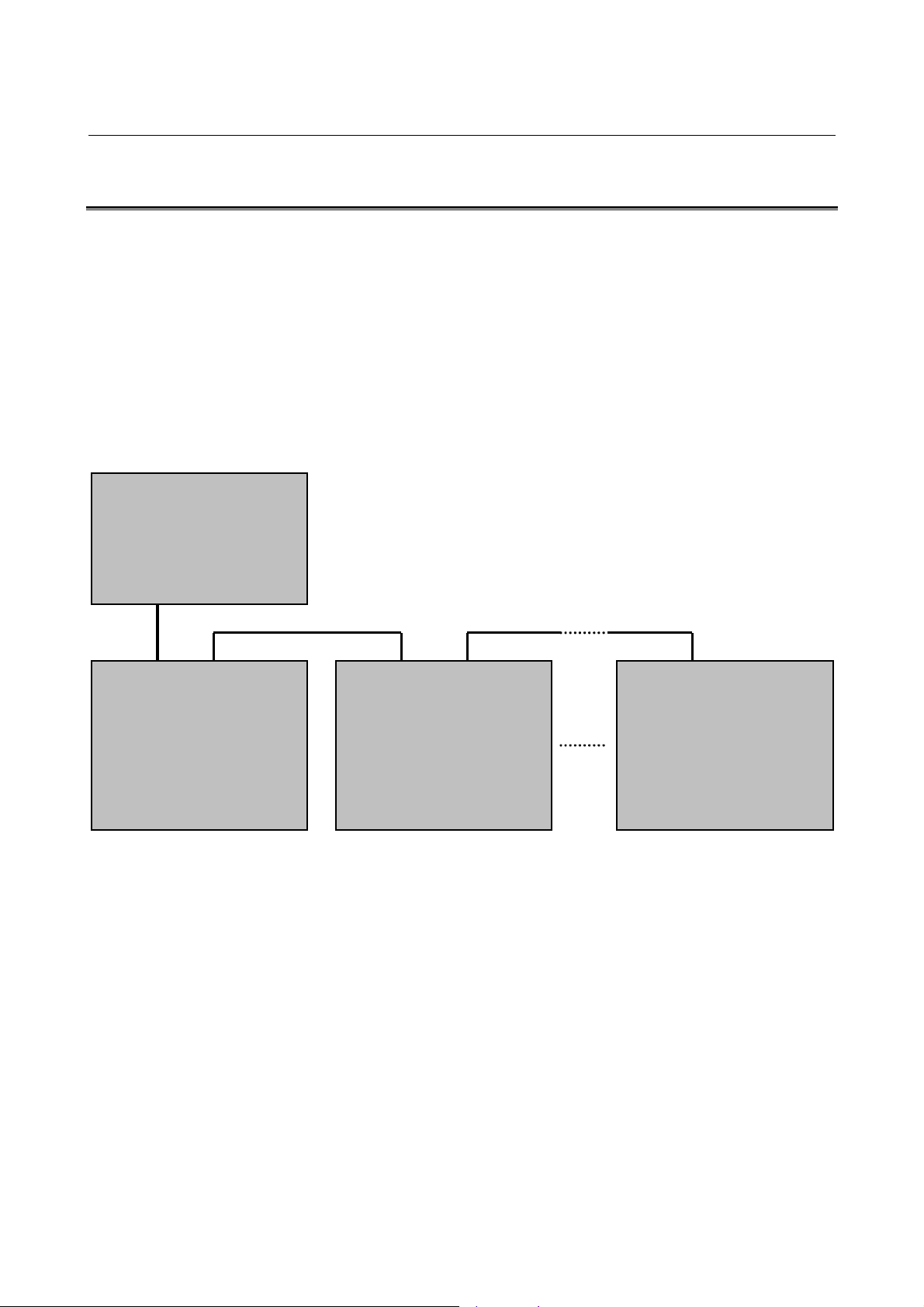
The I/O Link-II function has the features listed below.
(1) A connection can be made with devices (including devices
produced by other manufacturers) that conform to OPCN-1.
(2) The power to a slave station on the network can be turned on and
off at any time without affecting communications performed by
other devices.
(3) Up to thirty-one slave stations can be connected to one master
station.
(4) The slave function includes a global I/O transfer function
(allowing a slave station to receive DO data from other slave
stations).
<Master station>
16/18/21-B
16/18-C
LCD-mounted type 16i/18i/21i-A/B
Stand-alone type 16i/18i/21i-A
(OPCN-1-compliant products of other
manufacturers)
<Slave station> #1
16/18/21-B
16/18-C
LCD-mounted type 16i/18i/21i-A/B
Stand-alone type 16i/18i/21i-A
PM-D/F/H
PMi-D/H
(OPCN-1-compliant products of other
manufacturers)
<Slave station> #2
16/18/21-B
16/18-C
LCD-mounted type 16i/18i/21i-A/B
Stand-alone type 16i/18i/21i-A
PM-D/F/H
PMi-D/H
(OPCN-1-compliant products of other
manufacturers)
<Slave station> #31
16/18/21-B
16/18-C
LCD-mounted type 16i/18i/21i-A/B
Stand-alone type 16i/18i/21i-A
PM-D/F/H
PMi-D/H
(OPCN-1-compliant products of other
manufacturers)
- 10 -
Page 18

B-62714EN/04 SPECIFICATIONS 1.I/O LINK-II I/O FUNCTION
1.2 MASTER FUNCTION
The master function consists of the following function:
(1) DI/DO data transfer function
NOTE
FANUC I/O Link-II (master function) uses the
following services of OPCN-1:
(1) Initialization service
(2) Input/output service
(3) Reset service
- 11 -
Page 19
1.I/O LINK-II I/O FUNCTION SPECIFICATIONS B-62714EN/04
1.3 SLAVE FUNCTION
The slave function consists of the following functions:
(1) DI/DO data transfer function
(2) Global I/O transfer function (FANUC unique function)
(3) Capability of turning on and off the power to a slave station at
any time without affecting communications performed by other
devices
NOTE
FANUC I/O Link-II (slave function) uses the following
services of OPCN-1:
(1) Initialization service
(2) Input/output service
(3) Reset service
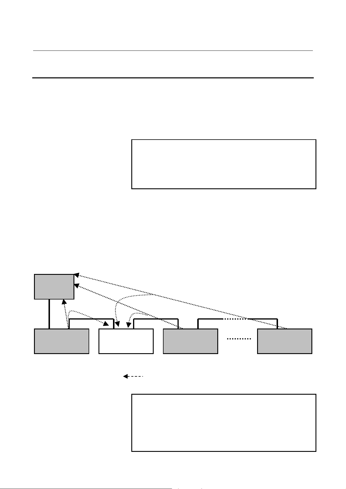
About the global I/O transfer function:
The figure below shows DI/DO data transfer performed between a
master station and slave stations #1 to #N. Suppose that a slave
station using the global I/O transfer function is a local slave station,
and the other slave stations are remote slave stations. Then, the local
slave station (#2) can receive DO data sent from the master station
and can also receive DO data sent to the master station from the
remote slave stations. So, the local slave station can make a ladder
reference.
Master
station
Slave station #1
[Remote slave
station]
Slave station #2
[Local slave
station]
NOTE
Slave station #3
[Remote slave
station]
DO data from slave stations #1 to #N (excluding #2)
Slave station #N
[Remote slave
station]
The global I/O transfer function is not a function
defined by OPCN-1 but a FANUC unique function.
This function can be used even when the network
includes products of other manufacturers (even as a
master station). In this case, however, the size of
data that can be transferred is limited.
- 12 -
Page 20

B-62714EN/04 SPECIFICATIONS 1.I/O LINK-II I/O FUNCTION
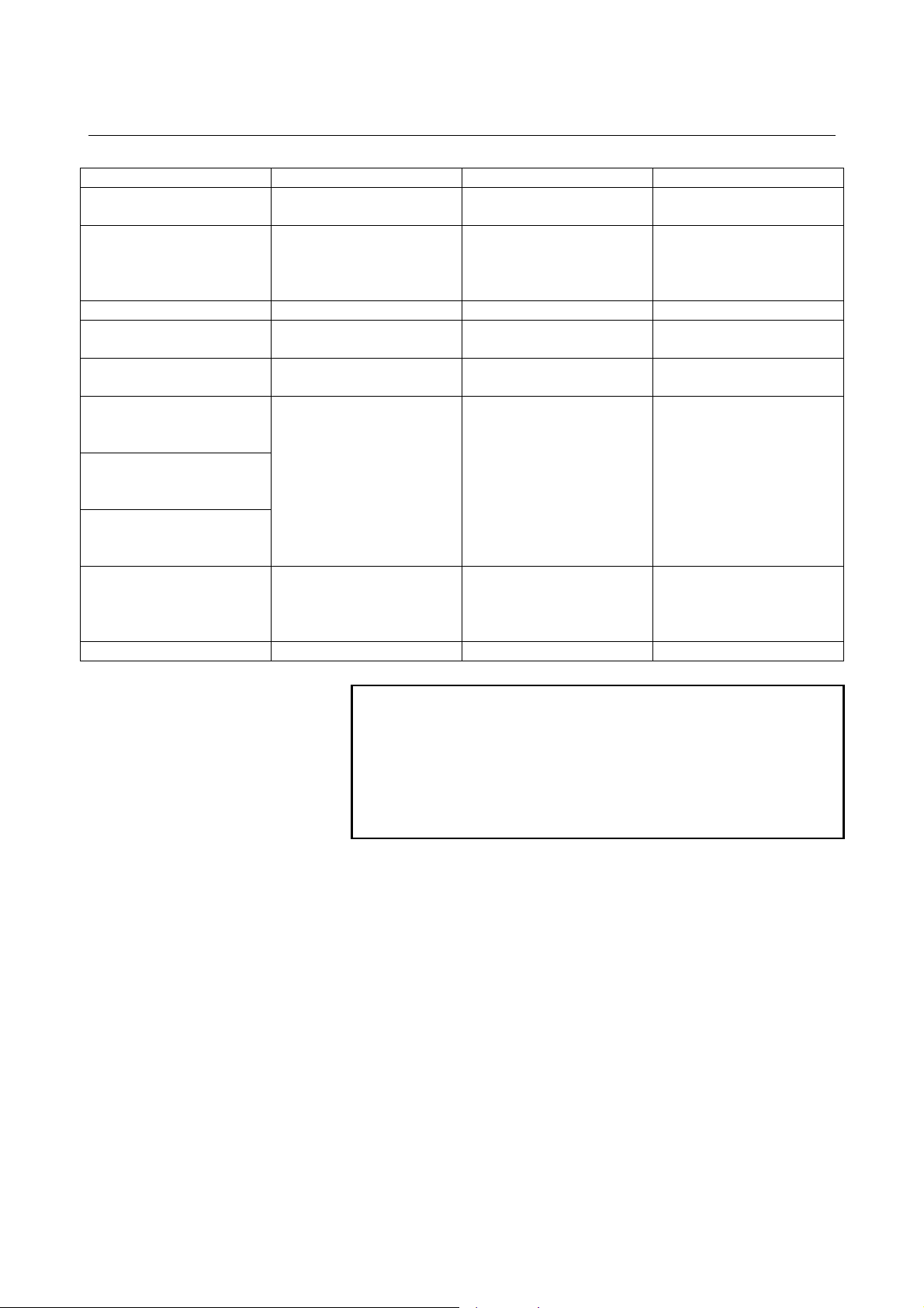
1.4 SPECIFICATIONS
Type Master station Master station Slave station
Applicable CNC 16/18/21-B, 16/18-C
Board (printed circuit board
drawing number)
Control software 6546 series 6546 series 6545 series
Maximum DI/DO size of the
DI/DO data transfer function
Maximum DI/DO size of the
global I/O transfer function
DI/DO allocatable area of
the DI/DO data transfer
function
DI/DO allocatable area of
the global I/O transfer
function
Status information
allocatable area
Reference items of this
manual
JEMA net --- --- ---
I/O Link-II board
A16B-2202-0152
62 bytes/62 bytes (16/18-C)
32 bytes/32 bytes
(16/18/21-B)
--- --- 48 bytes
R0000-R0999 for both DI
and DO
(PMC-SA1/SA3)
R0000-R1499 for both DI
and DO
(PMC-SB3/SC3/SB5)
R0000-R2999 for both DI
and DO
(PMC-SB4/SC4/SB6)
I,II
III-1.1,III-1.3
IV-1,IV-2
V-1
LCD-mounted type
16i/18i/21i-A/B
I/O Link-II board
A20B-8100-0250
128 bytes/128 bytes
R0000-R0999 for both
DI and DO
(PMC-SA1/SA5)
R0000-R1499 for both
DI and DO
(PMC-SB5)
R0000-R2999 for both
DI and DO
(PMC-SB6)
R0000-R7999 for both
DI and DO
(PMC-SB7)
I,II
III-1.1, III-1.3
IV-1,IV-3
V-2
16/18/21-B, 16/18-C
I I/O Link-II board
A16B-2202-0152
62 bytes/62 bytes (16/18-C)
32 bytes/32 bytes (16/18/21-B)
R0000-R0999 for both DI and
DO
(PMC-SA1/SA3)
R0000-R1499 for both DI and
DO
(PMC-SB3/SC3/SB5)
R0000-R2999 for both DI and
DO
(PMC-SB4/SC4/SB6)
I,II
III-1.2, III-1.3
IV-1,IV-2
V-1
- 13 -
Page 21

1.I/O LINK-II I/O FUNCTION SPECIFICATIONS B-62714EN/04
Type Master station Master station Slave station
Applicable CNC
Board (printed circuit board
drawing number)
Control software 6545 series 8816 series 8816 series
Maximum DI/DO size of the
DI/DO data transfer function
Maximum DI/DO size of the
global I/O transfer function
DI/DO allocatable area of
the DI/DO data transfer
function
DI/DO allocatable area of
the global I/O transfer
function
Status information
allocatable area
Reference items of this
manual
JEMA net --- --- ---
LCD-mounted type
16i/18i/21i-A/B
I/O Link-II board
A20B-8100-0250
128 bytes/128 bytes
48 bytes 48 bytes(Caution) 48 bytes(Caution)
R0000-R0999 for both DI
and DO
(PMC-SA1/SA5)
R0000-R1499 for both DI
and DO
(PMC-SB5)
R0000-R2999 for both DI
and DO
(PMC-SB6)
R0000-R7999 for both DI
and DO
(PMC-SB7)
I,II
III-1.2,III-1.3
IV-1,IV-3
V-2
PM-D/F/H
I/O Link-II board
A20B-2100-0041, 0040
32 bytes/32 bytes (PM-F/H)
64 bytes/64 bytes (PM-D)
DI : X1002-X1063
DO : Y1002-Y1063
(PMC-PA1/PA3)
R0000-R0999 for both DI
and DO
(PMC-PA1/PA3)
I,II
III-3.1,III-3.2
IV-1,IV-5
V-4
PMi-D/H
I/O Link-II board
A20B-8100-0310
32 bytes.32 bytes
DI : X1032-X1063
DO : Y1032-Y1063
(PMC-SB5/SB6)
R0000-R0999 for both DI
and DO
(PMC-SB5/SB6)
I,II
III-3.1,III-3.2
IV-1,IV-6.1, IV-6.2, IV-6.3
V-5.1
- 14 -
Page 22
B-62714EN/04 SPECIFICATIONS 1.I/O LINK-II I/O FUNCTION
Type Master station Slave station Slave station
Applicable CNC
Board (printed circuit board
drawing number)
Control software 654B series 654A series 654A series
Maximum DI/DO size of the
DI/DO data transfer function
Maximum DI/DO size of the
global I/O transfer function
DI/DO allocatable area of
the DI/DO data transfer
function
DI/DO allocatable area of
the global I/O transfer
function
Status information
allocatable area
Reference items of this
manual
JEMA net OPCN-1 certified device OPCN-1 certified device OPCN-1 certified device
Stand-alone type
16i/18i/21i-A
I/O Link-II board B1
A20B-8100-0380
I/O Link-II board B2
A20B-8100-0381
128 bytes/128 bytes 128 bytes/128 bytes 128 bytes/128 bytes
--- 48 bytes 48 bytes
R0000-R0999 for both DI
and DO
(PMC-SA1/SA5)
R0000-R1499 for both DI
and DO
(PMC-SB5)
R0000-R2999 for both DI
and DO
(PMC-SB6)
I,II
III-2.1,III-2.3
IV-1,IV-4
V-3
Stand-alone type
16i/18i/21i-A
I/O Link-II board B1
A20B-8100-0380
I/O Link-II board B2
A20B-8100-0381
R0000-R0999 for both DI
and DO
(PMC-SA1/SA5)
R0000-R1499 for both DI
and DO
(PMC-SB5)
R0000-R2999 for both DI
and DO
(PMC-SB6)
I,II
III-2.2,III-2.3
IV-1,IV-4
V-3
PMi-D/H
I/O Link-II board B
A20B-8100-0381
R0000-R1499 for both DI
and DO
(PMC-SB5)
R0000-R2999 for both DI
and DO
(PMC-SB6)
I,II
III-2.2,III-2.3
IV-1, IV-6.1, IV-6.2, IV-6.4
V-5.2
CAUTION
The I/O Link-II board (A20B-2100-041) for PM-D/H
and the I/O Link-II board (A20B-8100-0310) for PMiD/H cannot use the global I/O transfer function
because of a mixture with the other stations (master
station and slave stations) using I/O Link-II boards
B, B1, and B2.
- 15 -
Page 23

1.I/O LINK-II I/O FUNCTION SPECIFICATIONS B-62714EN/04
1.5 GLOSSARY
Key terms used this manual are explained below.
OPCN-1 (formerly called JPCN-1 or JEMA net)
Field network defined by the Japan Electrical Manufacturer's
Association
OPCN-1 certified device
FANUC device that passed the OPCN-1 certification test
Certification number: J990705JPCNM026
Date of certification: July 5, 1999
Master station
Station that establishes and cancels logical communication paths to
multiple slave stations, manages the data transmission service issue
sequence and error recovery sequence, and performs I/O transfer.
One OPCN-1 network can include only one master station.
Slave station
Initialization service
Input/output service
Reset service
Initial state
Station that exercises communication control and performs I/O
transfer to and from the master station according to instructions from
the master station. One OPCN-1 network can include up to 31 slave
stations.
Service defined by OPCN-1 for information exchange and setting to
establish logical communication paths between the master station and
slave stations. When the initialization service is executed successfully,
input/output service can be started.
Service defined by OPCN-1 for DI/DO data transfer between the
master station and slave stations
Service defined by OPCN-1 for the master station to reset slave
stations to the initial state
State where no logical communication path is established
Detachment
Disconnection
State where communication (input/output service being performed)
with the remote station is disabled
State where communication is not performed (such as in the initial
state or detached state)
- 16 -
Page 24

B-62714EN/04 SPECIFICATIONS 1.I/O LINK-II I/O FUNCTION
DI data
Input data when viewed from the local station (master station or slave
station)(Caution)
DO data
Output data when viewed from the local station (master station or
slave station)(Caution)
CAUTION
In the OPCN-1 specifications, data input/output is
defined as data input/output viewed from the master
station. Note that the use of the term in this manual
for slave stations is opposite to the definition in the
OPCN-1 specifications.
For communication with devices of other
manufacturers, check the definition of data
input/output.
DI/DO data transfer function
Function for exchanging DI/DO data between the master station and
slave stations of I/O Link-II. This function is implemented by
input/output service of OPCN-1.
Global I/O transfer function
FANUC unique function. When DI/DO data is exchanged between
the master station and multiple slave stations, a slave station receives
DO data sent from the other slave stations to the master station, thus
achieving I/O transfer between the slave stations.
Successive error detach detection counter
Maximum allowable number of successive communication errors.
When this maximum number is exceeded, a detachment is detected.
One scan
Executing input/output service once for all slave stations connected to
the network
Slave type
Initialization service parameter defined by OPCN-1 for determining
the type of communication between the master station and slave
stations
- 17 -
Page 25

1.I/O LINK-II I/O FUNCTION SPECIFICATIONS B-62714EN/04
stypeM
Slave type set by the master station
stypeM bit 7bit 6bit 5bit 4bit 3bit 2bit 1bit 0
Bits 7 and 6 : Reserved (0 at all times)
Bit 5 : SA (whether information and I/O from the master station to a slave
station are specified)
- When SA = 0, information and I/O from the master station to a
slave station are not specified.
- When SA = 1, information and I/O from the master station to a
slave station are specified
Bit 4 : ST (whether a type of I/O from the master station to a slave station is
specified)
- When ST = 0, no type of I/O from the master station to a slave
station is specified.
- When ST = 0, a type of I/O from the master station to a slave
station is specified.
NOTE
The setting of bits 3 to 1 is valid when ST = 1.
stypeS
Bit 3 : DW (data write)
Set DW = 1 to enable data write service.
Bit 2 : DR (data read)
Set DR = 1 to enable data read service.
Bit 1 : DO (output)
Set DO = 1 to perform input/output service and enable output.
Bit 0 : DI (input)
Set DI = 1 to perform input/output service and enable input.
Slave type set by a slave station
stypeS bit 7bit 6bit 5bit 4bit 3bit 2bit 1bit 0
Bits 7 to 4 : Reserved (0 at all times)
Bit 3 : DW (data write)
Set DW = 1 to enable data write service.
Bit 2 : DR (data read)
Set DR = 1 to enable data read service.
Bit 1 : DO (output from the master station) when viewed from the master
station
Set DO = 1 to perform input/output service and enable output.
Bit 0 : DI (input to the master station) when viewed from the master station
Set DI = 1 to perform input/output service and enable input.
- 18 -
Page 26

III. OPERATION
Page 27

B-62714EN/04 OPERATION 1.16/18/21-B, 16/18-C, LCD-MOUNTED TYPE 16i/18i/21i-A/B
1 16/18/21-B, 16/18-C, LCD-MOUNTED
TYPE 16i/18i/21i-A/B
This chapter describes the setting procedure for operating the master
function and slave function.
NOTE
The parameters related to the I/O Link-II function are
stored in the SRAM on an I/O Link-II board. When
using an I/O Link-II board for the first time, initialize
the SRAM on the board according to Section 1.3,
"SETTING" of Part V, "MAINTENANCE" (for
16/18/21-B and 16/18-C) or Section 2.3 "SETTING"
of the same part (for 16i/18i/21i-A/B).
- 21 -
Page 28
1.16/18/21-B, 16/18-C, LCD-MOUNTED TYPE 16i/18i/21i-A/B OPERATION B-62714EN/04
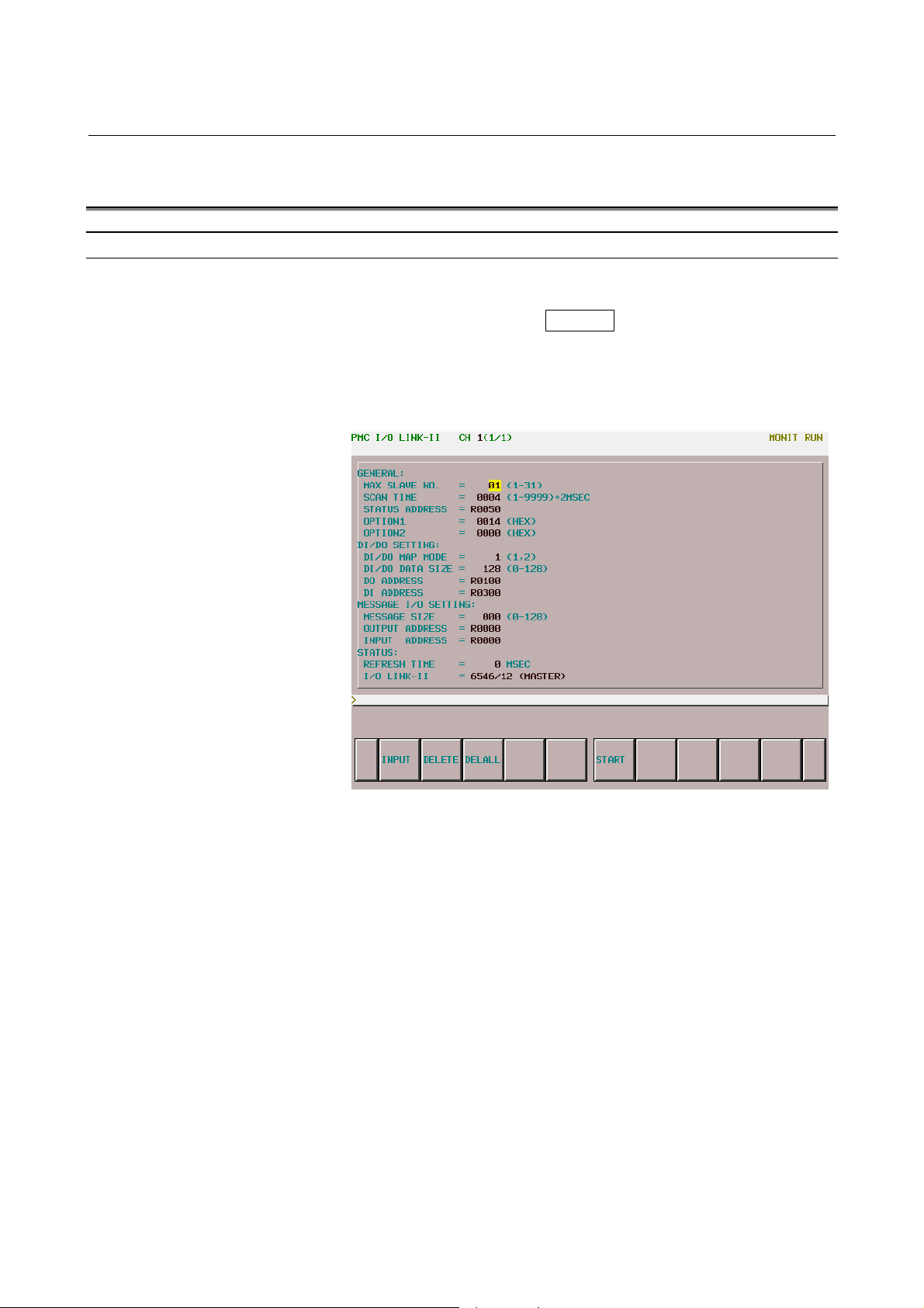
1.1 MASTER FUNCTION
Display of the setting screen
Procedure
(1) Press the function key SYSTEM, then select the soft key [PMC]
to switch to the PMC screen.
(2) Select the soft keys [PMCDGN], [I/OCHK], and [IOLNK2] in
this order. Screen 1-1 appears.
- 22 -
Screen 1-1
Page 29

B-62714EN/04 OPERATION 1.16/18/21-B, 16/18-C, LCD-MOUNTED TYPE 16i/18i/21i-A/B
Setting items and display items
Setting items
Table III-1-1
Item Description
Maximum slave station number used for
MAX SLAVE NO.
SCAN TIME
STATUS ADDRESS
OPTION1
OPTION2
DI/DO MAP MODE
DI/DO DATA SIZE
DO ADDRESS
DI ADDRESS
MESSAGE SIZE Not used
OUTPUT ADDRESS Not used
INPUT ADDRESS Not used
communication with the master station.
Setting range: 1 to 31
Interval for performing one scan of input/output
service.
Set a value greater than the value of REFRESH
TIME.
Guideline for setting:
SCAN TIME = MAX SLAVE NO. × 2 + 2
Setting unit: 2 msec
Setting range: 1 to 9999
Example of setting:
When 4 is set in SCAN TIME, the setting of 8 msec
is assumed.
Start address of an area for storing communication
status.
Setting range: R area of the PMC
Slave station communication monitoring time
Recommended setting: 14 [hexadecimal] → 40 msec
Setting unit: msec
Setting range: 03 to D0 (hexadecimal)
Successive error detach detection counter.
Recommended setting: 3 [hexadecimal]
Setting range: 00 to FF (hexadecimal)
When the default value 0 is used, the setting of 3 is
assumed for operation.
Determines the method of allocating a DI/DO data
area.
Setting: 1, 2
1: A DI data area and DO data area are allocated for
the number of stations set in MAX SLAVE NO..
2: A DI data area is allocated for the number of
stations set in MAX SLAVE NO., and a DO data
area is allocated for one station.
DI/DO data area size.
Setting range: 0 to 62 (16/18/21-B, 16/18-C)
Setting range: 0 to 128 (LCD-mounted type
16i/18i/21i-A)
(Unit: Bytes)
DO data area start address.
Setting range: R area of the PMC
DI data area start address.
Setting range: R area of the PMC
- 23 -
Page 30

1.16/18/21-B, 16/18-C, LCD-MOUNTED TYPE 16i/18i/21i-A/B OPERATION B-62714EN/04
NOTE
The baud rate cannot be changed, but is fixed at 1
Mbps.
Display items
Table III-1-1
Item Description
Interval at which DI data from all slave stations set in
REFRESH TIME.
I/O LINK-II
MAX SLAVE NO. is reflected in the R area of the PMC.
Unit: 1 msec
The series and edition of the EPROM installed on the
I/O Link-II board are displayed.
- 24 -
Page 31

B-62714EN/04 OPERATION 1.16/18/21-B, 16/18-C, LCD-MOUNTED TYPE 16i/18i/21i-A/B
Operations of the setting screen
Setting parameters
(1) Place the CNC in the MDI mode.
(2) Press the function key SYSTEM
, then select the soft key [PMC]
to switch to the PMC screen.
(3) Select the soft keys [PMCDGN], [I/OCHK], and [IOLNK2] in
this order. Screen 1-1 appears.
(4) With the cursor keys, move the cursor to an item for which data
is to be entered.
(5) Enter data with the MDI keys.
(6) Select the soft key [INPUT] or press the function key INPUT
to
execute the input of data.
Example: Setting 2 in MAX SLAVE NO.
(a) Move the cursor to MAX SLAVE NO..
(b) Enter 2 with the MDI key.
(c) Select the soft key [INPUT] or press the function key
INPUT
to execute the input of data.
Thus, the set data is stored in the nonvolatile memory on the I/O LinkII board.
- 25 -
Page 32

1.16/18/21-B, 16/18-C, LCD-MOUNTED TYPE 16i/18i/21i-A/B OPERATION B-62714EN/04
Deleting parameters
(1) Place the CNC in the MDI mode.
(2) Press the function key SYSTEM
(3) Select the soft keys [PMCDGN], [I/OCHK], and [IOLNK2] in
(4) With the cursor keys, move the cursor to an item whose setting
(5) Select the soft key [DELETE] or press the function key
Thus, the data is deleted from the nonvolatile memory on the I/O
Link-II board.
Deleting parameters in a batch
(1) Place the CNC in the MDI mode.
(2) Press the function key SYSTEM
(3) Select the soft keys [PMCDGN], [I/OCHK], and [IOLNK2] in
to switch to the PMC screen.
this order. Screen 1-1 appears.
to be deleted.
DELETE
to switch to the PMC screen.
this order. Screen 1-1 appears.
to delete the data.
, then select the soft key [PMC]
, then select the soft key [PMC]
Restart
(4) Select the soft key [DELALL] to delete all data in a batch.
Thus, all data is deleted in a batch from the nonvolatile memory on
the I/O Link-II board.
(1) Place the CNC in the MDI mode.
(2) Press the function key SYSTEM
to switch to the PMC screen.
(3) Select the soft keys [PMCDGN], [I/OCHK], and [IOLNK2] in
this order. Screen 1-1 appears.
(4) Select the soft key [START]. The master function is restarted
with the current settings displayed on Screen 1-1.
, then select the soft key [PMC]
- 26 -
Page 33

B-62714EN/04 OPERATION 1.16/18/21-B, 16/18-C, LCD-MOUNTED TYPE 16i/18i/21i-A/B
(5) If the settings are correct, LINK STARTED is displayed, and
initialization service is performed.
(6) If a setting item is incorrect, START ERROR is displayed, and
the system waits for the incorrect setting item to be corrected.
CAUTION
When the soft key [START] is selected, the set
parameters are updated, and reset service is also
performed for slave stations #1 to #[MAX SLAVE
NO].
So, the same processing as performed when the
power is turned on again after resetting the network
to the initial state (initialization service for the slave
stations → input/output service) is performed.
- 27 -
Page 34

1.16/18/21-B, 16/18-C, LCD-MOUNTED TYPE 16i/18i/21i-A/B OPERATION B-62714EN/04
DI/DO data allocation of the master function
DO data allocation (when DI/DO MAP MODE = 1)
A DO area is allocated for each slave.
[DO ADDRESS]
+[DI/DO DATA SIZE] ×1
+[DI/DO DATA SIZE] ×2
+[DI/DO DATA SIZE] ×3
+[DI/DO DATA SIZE]×
([MAX SLAVE NO]-1)
DO data from the master station to
slave station #1
DO data from the master station to
slave station #2
DO data from the master station to
slave station #3
DO data from the master station to
slave station #4
::
::
::
DO data from the master station to
slave station #[MAX SLAVE NO]
Example:
When [MAX SLAVE NO] = 2, [DI/DO MAP MODE] = 1, [DO
ADDRESS] = R0100, and [DI/DO ADDRESS SIZE] = 10, DO
data is allocated as follows:
R0100
R0110
DO data from the master station to
slave station #1
DO data from the master station to
slave station #2
↑
[DI/DO DATA SIZE]
↓
DO data allocation (when DI/DO MAP MODE = 2)
Common DO data is allocated for all slaves.
[DO ADDRESS] DO data from the master station to
slave stations #1 to slave station
#[MAX SLAVE NO]
- 28 -
↑
[DI/DO DATA SIZE]
↓
Page 35

B-62714EN/04 OPERATION 1.16/18/21-B, 16/18-C, LCD-MOUNTED TYPE 16i/18i/21i-A/B
DI data allocation (when DI/DO MAP MODE = 1 or 2)
[DI ADDRESS]
+[DI/DO DATA SIZE]×1
+[DI/DO DATA SIZE]×2
+[DI/DO DATA SIZE]×3
+[DI/DO DATA SIZE]×
([MAX SLAVE NO]-1)
DI data from slave station #1 to the
master station
DI data from slave station #2 to the
master station
DI data from slave station #3 to the
master station
DI data from slave station #4 to the
master station
::
::
::
DI data from slave station #[MAX
SLAVE NO] to the master station
Example:
When [MAX SLAVE NO] = 3, [DI ADDRESS] = R0300, and
[DI/DO ADDRESS SIZE] = 10, DI data is allocated as follows:
R0300
R0310
R0320
DI data from slave station #1 to the
master station
DI data from slave station #2 to the
master station
DI data from slave station #3 to the
master station
↑
[DI/DO DATA SIZE]
↓
- 29 -
Page 36

1.16/18/21-B, 16/18-C, LCD-MOUNTED TYPE 16i/18i/21i-A/B OPERATION B-62714EN/04
Communication status for ladder detection of the master function
Communication status allocation
[STATUS ADDRESS]
ERROR STATUS
ERROR STATUS
+1
+2
+3
+[MAX SLAVE NO]
Status of communication with
slave station #1
Status of communication with
slave station #2
Status of communication with
slave station #3
::
::
::
Status of communication with
slave station #[MAX SLAVE NO]
ERROR STATUS (1 byte):
Communication line errors detected by the master station are
indicated.
bit 7bit 6bit 5bit 4bit 3bit 2bit 1bit 0
Bit 7 : Reserved (0 at all time)
Bit 6 : Short frame error
Bit 5 : Abort detection
Bit 4 : Detection of data consisting of an incorrect number of bits
Bit 3 : Overrun error detection
Bit 2 : FCS error detection
Bits 1, 0 : Reserved (0 at all times)
NOTE
Many errors are caused by hardware failures (on
communication boards or communication cables)
and noise. Recheck the method of communication
cable connection, terminating resistor, and noise
protection.
- 30 -
Page 37

B-62714EN/04 OPERATION 1.16/18/21-B, 16/18-C, LCD-MOUNTED TYPE 16i/18i/21i-A/B
Status of communication with remote slave stations
Status of communication with remote slave stations #1 to #[MAX
SLAVE NO]:
The status of communication with each slave station is indicated (1
byte for each).
bit 7bit 6bit 5bit 4bit 3bit 2bit 1bit 0
Bit 7: LINK STATUS (status of the link with a slave station)
- When LINK STATUS = 0, the link is disconnected.
- When LINK STATUS = 1, communication is performed
normally.
Bits 6 to 1: Reserved (0 at all times)
Bit 0: Communication error flag
- When communication error flag = 0, the successive error detach
detection counter is not exceeded.
- When communication error flag = 1, the successive error detach
detection counter is exceeded.
- 31 -
Page 38

1.16/18/21-B, 16/18-C, LCD-MOUNTED TYPE 16i/18i/21i-A/B OPERATION B-62714EN/04
1.2 SLAVE FUNCTION
Display of the setting screen
Procedure
(1) Press the function key SYSTEM, then select the soft key [PMC]
to switch to the PMC screen.
(2) Select the soft keys [PMCDGN], [I/OCHK], and [IOLNK2] in
this order. Screen 1-2 appears.
- 32 -
Screen 1-2
Page 39

B-62714EN/04 OPERATION 1.16/18/21-B, 16/18-C, LCD-MOUNTED TYPE 16i/18i/21i-A/B
Setting items and display items
Setting items
Table III-1-3
Item Description
Maximum slave station number used for
MAX SLAVE NO.
SCAN TIME
STATUS ADDRESS
OPTION1
OPTION2 Not used
DI/DO MAP MODE
DI/DO DATA SIZE
DO ADDRESS
DI ADDRESS
MESSAGE SIZE Not used
OUTPUT ADDRESS Not used
INPUT ADDRESS Not used
communication with the master station.
Setting range: 1 to 31(Note)
Station number of the slave station.
Setting range: 1 to 31(Note)
Start address of an area for storing communication
status.
Setting range: R area of the PMC
Slave station communication monitoring time
Guideline for setting:
OPTION1 = MAX SLAVE NO. × 5
Setting unit: 100 msec
Setting range: 0000 to 1000 [hexadecimal]
When the default value 0 is used, a value
determined by the guideline for setting is assumed
for operation.
Determines the method of allocating a DI/DO data
area.
Setting: 0, 2
0: DI/DO data transfer function
A DI data area and DO data area are allocated for
one station.
2: Global I/O transfer function(Caution)
A DI data area is allocated for the number of
stations set in MAX SLAVE NO. plus 1, and a DO
data area is allocated for one station.
DI/DO data area size.
For the DI/DO data transfer function
Setting range: 0 to 32 (16/18/21-B)
Setting range: 0 to 62 (16/18-C)
Setting range: 0 to 128 (LCD-mounted type
16i/18i/21i-A)
For the global I/O transfer function
Setting range: 0 to 48
(Unit: Bytes)
DO data area start address
Setting range: R area of the PMC
DI data area start address
Setting range: R area of the PMC
CAUTION (*1)
When using the global I/O transfer function, ensure
that the DI data size and DO data size of each slave
station on the network do not exceed 48 bytes.
- 33 -
Page 40

1.16/18/21-B, 16/18-C, LCD-MOUNTED TYPE 16i/18i/21i-A/B OPERATION B-62714EN/04
NOTE
- The baud rate cannot be changed but is fixed at 1
Mbps.
- When using the global I/O transfer function, set
slave station numbers sequentially to allocate an
area efficiently.
Display items
Table III-1-4
Item Description
I/O LINK-II
The series and edition of the EPROM installed on
the I/O Link-II board are displayed.
- 34 -
Page 41

B-62714EN/04 OPERATION 1.16/18/21-B, 16/18-C, LCD-MOUNTED TYPE 16i/18i/21i-A/B
Operations of the setting screen
Setting parameters
(1) Place the CNC in the MDI mode.
(2) Press the function key SYSTEM
, then select the soft key [PMC]
to switch to the PMC screen.
(3) Select the soft keys [PMCDGN], [I/OCHK], and [IOLNK2] in
this order. Screen 1-2 appears.
(4) With the cursor keys, move the cursor to an item for which data
is to be entered.
(5) Enter data with the MDI keys.
(6) Select the soft key [INPUT] or press the function key INPUT
to
execute the input of data.
Example: Setting 2 in MAX SLAVE NO.
(a) Move the cursor to MAX SLAVE NO..
(b) Enter 2 with the MDI key.
(c) Select the soft key [INPUT] or press the function key
INPUT
to execute the input of data.
Thus, the set data is stored in the nonvolatile memory on the I/O LinkII board.
- 35 -
Page 42

1.16/18/21-B, 16/18-C, LCD-MOUNTED TYPE 16i/18i/21i-A/B OPERATION B-62714EN/04
Deleting parameters
(1) Place the CNC in the MDI mode.
(2) Press the function key SYSTEM
(3) Select the soft keys [PMCDGN], [I/OCHK], and [IOLNK2] in
(4) With the cursor keys, move the cursor to an item whose setting
(5) Select the soft key [DELETE] or press the function key
Thus, the data is deleted from the nonvolatile memory on the I/O
Link-II board.
Deleting parameters in a batch
(1) Place the CNC in the MDI mode.
(2) Press the function key SYSTEM
(3) Select the soft keys [PMCDGN], [I/OCHK], and [IOLNK2] in
to switch to the PMC screen.
this order. Screen 1-2 appears.
to be deleted.
DELETE
to switch to the PMC screen.
this order. Screen 1-2 appears.
to delete the data.
, then select the soft key [PMC]
, then select the soft key [PMC]
(4) Select the soft key [DELALL] to delete all data in a batch.
Thus, all data is deleted in a batch from the nonvolatile memory on
the I/O Link-II board.
- 36 -
Page 43

B-62714EN/04 OPERATION 1.16/18/21-B, 16/18-C, LCD-MOUNTED TYPE 16i/18i/21i-A/B
Restart
(1) Place the CNC in the MDI mode.
(2) Press the function key SYSTEM
to switch to the PMC screen.
(3) Select the soft keys [PMCDGN], [I/OCHK], and [IOLNK2] in
this order. Screen 1-2 appears.
(4) Select the soft key [START]. The slave function is restarted
with the current settings displayed on Screen 1-2.
(5) If the settings are correct, LINK STARTED is displayed, and
initialization service is awaited.
(6) If a setting item is incorrect, START ERROR is displayed, and
the system waits for the incorrect setting item to be corrected.
, then select the soft key [PMC]
NOTE
The soft key [START] provides an auxiliary way to
validate settings modified on this screen.
If the soft key [START] is selected after modifying
settings, communication may be suspended
halfway, and may not be performed normally,
depending on the state of the master station. In
such a case, restart the master station and slave
station.
- 37 -
Page 44

1.16/18/21-B, 16/18-C, LCD-MOUNTED TYPE 16i/18i/21i-A/B OPERATION B-62714EN/04
DI/DO data allocation of the slave function
DO data allocation
↑
[DI/DO DATA SIZE]
↓
[DO ADDRESS]
DO data from the local slave station to
the master station
DI data allocation when DI/DO data transfer is set (when DI/DO MAP MODE = 0)
↑
[DI/DO DATA SIZE]
↓
[DO ADDRESS]
DI data from the master station to the
local slave station
DI data allocation when global I/O transfer is set (when DI/DO MAP MODE = 2)
↑
[DI/DO DATA SIZE]
↓
[DO ADDRESS]
+[DI/DO DATA SIZE]×1
+[DI/DO DATA SIZE]×2
+[DI/DO DATA SIZE]×3
+[DI/DO DATA SIZE]×
[STATION NO]
+[DI/DO DATA SIZE]×
[MAX SLAVE NO]
DI data from the master station to the
local slave station
DO data from slave station #1 to the
master station
DO data from slave station #2 to the
master station
DO data from slave station #3 to the
master station
::
Not used.(The area for the local slave
station is not used. The area can be
used for other purposes such as a DO
data output area for the local station.)
::
DO data from slave station #[MAX
SLAVE NO] to the master station
Example:
When [STATION NO] = 2, [MAX SLAVE NO] = 3, [DI
ADDRESS] = R0300, and [DI/DO DATA SIZE] = 10, DI data is
allocated as follows:
R0300
R0310
R0320 Not used
R0330
DI data from the master station to
slave station #2
DO data from slave station #1 to the
master station
DO data from slave station #3 to the
master station
NOTE
For global I/O transfer, note the following when
allocating DI data:
- [DI/DO DATA SIZE] must match the maximum
size of other slaves.
- The total DI data area size required is [DI/DO
DATA SIZE] × [MAX SLAVE NO].
- 38 -
Page 45

B-62714EN/04 OPERATION 1.16/18/21-B, 16/18-C, LCD-MOUNTED TYPE 16i/18i/21i-A/B
Restrictions on the global I/O transfer function
Conditions for taking in DO data from a remote slave station to the master
station
When the two conditions below are satisfied, DO data from a remote
slave station to the master station is taken in.
Condition 1 : 48 bytes ≥ x bytes ≥ y bytes
where
x: Size of DI data from the master station to the local slave
station
y: Size of DO data from a remote slave station to the master
station
Condition 2 : Station m ≥ Station n
where
m: [MAX SLAVE NO] set at the local slave station
n: Station number of a remote slave station
Example:
When the station number of the local slave station is 2, there are
five remote slave stations, and each slave station is set as
follows:
- Setting of slave station #1: DO data size = 16 bytes
- Setting of slave station #2: [MAX SLAVE NO] = 4,
[STATION NO] = 2, [DI/DO MAP MODE] =2, [DI/DO
DATA SIZE] = 32
- Setting of slave station #3: DO data size = 32 bytes
- Setting of slave station #4: DO data size = 48 bytes
- Setting of slave station #5: DO data size = 8 bytes
According to the restrictions on global I/O transfer:
- Slave station #4 does not satisfy condition 1.
- Slave station #5 does not satisfy condition 2.
So, slave station #2 takes in only DO data from slave station #1
to the master station and DO data from slave station #3 to the
master station.
DI data allocation at slave station #2
DO data from slave station #1
(16 bytes) 32 bytes
Not used
(16 bytes)
Not used
(Area for the local station number)
DO data from slave station #3 32 bytes
Not used
(For slave station #4)
- 39 -
32 bytes
32 bytes
Page 46

1.16/18/21-B, 16/18-C, LCD-MOUNTED TYPE 16i/18i/21i-A/B OPERATION B-62714EN/04
Communication status for ladder detection of the slave function
Communication status allocation (when DI/DO MAP MODE = 0 [DI/DO data
transfer])
[STATUS ADDRESS] Status of communication with the
master station
Communication status allocation (when DI/DO MAP MODE = 2 [global I/O
transfer])
[STATUS ADDRESS] Status of communication with the
master station
+1 Status of communication with
slave station #1
+2 Status of communication with
slave station #2
+3 Status of communication with
slave station #3
::
(This area corresponds to the
+[STATION NO]
+[MAX SLAVE NO] Status of communication with
local slave station, and is not
used. This area cannot be used
for other purposes.)
::
slave station #[MAX SLAVE NO]
Status of communication with the master station
Status of communication with the master station (1 byte):
The status of communication with the master station is indicated.
bit 7bit 6bit 5bit 4bit 3bit 2bit 1bit 0
Bit 7 : LINK STATUS (status of the link with the master station)
- When LINK STATUS = 0, the link is disconnected.
- When LINK STATUS = 1, communication is performed
normally.
Bit 6 : Short frame error
Bit 5 : Abort detection
Bit 4 : Detection of data consisting of an incorrect number of bits
Bit 3 : Overrun error detection
Bit 2 : FCS error detection
Bits 1, 0 : Reserved (0 at all times)
NOTE
Many errors are caused by hardware failures (on
communication boards or communication cables)
and noise. Recheck the method of communication
cable connection, terminating resistor, and noise
protection.
- 40 -
Page 47

B-62714EN/04 OPERATION 1.16/18/21-B, 16/18-C, LCD-MOUNTED TYPE 16i/18i/21i-A/B
Status of communication with remote slave stations
Status of communication with remote slave stations #1 to #[MAX
SLAVE NO]:
The status of reception of DO data from remote slave stations to
the master station is indicated (1 byte for each).
bit 7bit 6bit 5bit 4bit 3bit 2bit 1bit 0
Bit 7 : LINK STATUS (status of the link with the master station)
- When LINK STATUS = 0, the link is disconnected.
- When LINK STATUS = 1, communication is performed
normally.
Bits 6 to 0 : Reserved (0 at all times)
- 41 -
Page 48

1.16/18/21-B, 16/18-C, LCD-MOUNTED TYPE 16i/18i/21i-A/B OPERATION B-62714EN/04
1.3 DATA CONCURRENCY
When DI data is handled by a ladder program, the I/O Link-II function
guarantees the concurrency of data on a byte-by-byte basis, but does
not guarantee the concurrency of multiple bytes of data.
The I/O Link-II function does not exchanges data in synchronism with
a ladder program, so that the function does not guarantees the
concurrency of DI data consisting of 2 bytes or more. This means that
when a ladder program reads 2-byte DI data, for example, the higher
byte and lower byte of the data may be updated at different timings.
Example where concurrency is not guaranteed
When the 2-byte data 1234 (hex) is entered from the I/O Link-II board
to the area R0300 set to the value 0000 (hex), the ladder program may
read the value 0034 (hex).
DI data R area of the PMC
R0300 00 00
34
R0300 00 34
12 If the ladder program reads R0300
during this period, 0034 (hex) is read.
R0300 12 34
Example of countermeasure: Control using synchronization flags
Concurrency can be guaranteed by providing a synchronization flag
before and after multi-byte data and synchronizing the data with the
flags. An example of guaranteeing the concurrency of 6-byte data is
given below.
(1) Data structure
A synchronization flag is prepared at the byte position preceding
the 6-byte data and at the byte position following the 6-byte data,
thus allocating an 8-byte area in total.
R0099 Synchronization flag 1
R0100
: Data section
R0105
R0106 Synchronization flag 2
(2) Processing on the data write side
The data is updated using the procedure below.
1 Synchronization flag 1 is incremented.
2 The data section is updated.
3 The same value as set in synchronization flag 1 is set in
synchronization flag 2.
- 42 -
Page 49

B-62714EN/04 OPERATION 1.16/18/21-B, 16/18-C, LCD-MOUNTED TYPE 16i/18i/21i-A/B
(3) Processing on the data read side
The data is processed using the procedure below.
1 At the start of the second level, the 8 bytes are copied from
R0099 to the synchronization area R0199.
2 A check is made to see if R0199 = R0206.
3 If R0199 = R0206, R0200 is handled as 6-byte data.
CAUTION
If the size of the data section to be synchronized is
increased by combining multiple bytes of data,
synchronization may become difficult.
In such a case, divide the data section on a
variable-by-variable basis before setting
synchronization flags.
- 43 -
Page 50

2.LCD-MOUNTED TYPE 16i/18i/21i-A, Power Mate i-D/H OPERATION B-62714EN/04
2 LCD-MOUNTED TYPE 16i/18i/21i-A,
Power Mate i-D/H
This chapter describes the setting procedure for operating the master
function and slave function.
NOTE
Notes on PMi-D/H
-With PMi-D/H, only the slave function can be
used.
-With PMi-D/H, the I/O Link-II board (A20B-8100-
0310) and I/O Link-II board B (A20B-8100-0381)
can be used.
This chapter provides descriptions based on the
use of I/O Link-II B. When using the I/O Link-II
board, the same specifications as for Power
Mate-D/F/H described in Chapter 3 are
applicable. So, see Chapter 3.
- 44 -
Page 51

B-62714EN/04 OPERATION 2.LCD-MOUNTED TYPE 16i/18i/21i-A, Power Mate i-D/H
2.1 MASTER FUNCTION
Display of the setting screen
Procedure
(1) Press the function key SYSTEM, then select the soft key [PMC]
to switch to the PMC screen.
(2) Select the soft keys [PMCDGN], [I/OCHK], and [IOLNK2] in
this order. Screen 2-1 appears.
Screen 2-1
(3) Select the soft key [MASTER]. Screen 2-2 appears.
Screen 2-2
- 45 -
Page 52

2.LCD-MOUNTED TYPE 16i/18i/21i-A, Power Mate i-D/H OPERATION B-62714EN/04
(4) Select the soft key [ADDR] on Screen 2-2. Screen 2-3 appears.
When setting 15 stations or more, switch the screen with the
page keys ↑
and ↓ .
Screen 2-3
- 46 -
Page 53

B-62714EN/04 OPERATION 2.LCD-MOUNTED TYPE 16i/18i/21i-A, Power Mate i-D/H
Setting items and display items
Setting items
Table III-2-1
Item Description
Maximum slave station number used for
MAX SLAVE NO.
SCAN TIME
BAUD-RATE
STATUS ADDRESS
OPTION1 Not used
OPTION2
DO ADDR
DO SIZ
DI ADDR
DI SIZ
communication with the master station.
Setting range: 1 to 31
Interval for performing one scan of input/output
service. A maximum speed is set automatically
according to [MAX SLAVE NO], so that this parameter
need not be set.
Communication speed.
Setting range: 0 to 3
0: 1.0 Mbps
1: 500 kbps
2: 250 kbps
3: 125 kbps
Two methods of setting are available:
- Input using numeric keys
- Input by soft key selection
(Displayed when the cursor is placed on this
parameter)
Start address of an area for storing communication
status.
Setting range: R area of the PMC
The storing of communication status can be disabled
by selecting the soft key [DISABLE] displayed when
the cursor is placed on this parameter.
When the storing of communication status is
disabled, "----" is displayed.
Successive error detach detection counter.
Recommended setting: 3 [hexadecimal]
Setting range: 00 to FF (hexadecimal)
When the default value 0 is used, the setting of 3 is
assumed for operation.
DO data area start address.
Setting range: R area of the PMC
DO data area size.
Setting range: 0 to 128
(Unit: Bytes)
When DO is not used, set 0.
DI data area start address.
Setting range: R area of the PMC
DI data area size.
Setting range: 0 to 128
(Unit: Bytes)
When DI is not used, set 0.
- 47 -
Page 54

2.LCD-MOUNTED TYPE 16i/18i/21i-A, Power Mate i-D/H OPERATION B-62714EN/04
Table III-2-1
Item Description
Parameter stypeM for initializing slave stations.
Setting range: 31 to 33 (hexadecimal)
Set one of the following values according to the type
TYPE
MAXT
REFRESH TIME
of communication:
- When enabling both DO and DI: 33 (hexadecimal)
- When enabling both DI only: 31 (hexadecimal)
- When enabling both DO only: 32 (hexadecimal)
Parameter max_int (slave station communication
monitoring time) for initializing slave stations.
Setting range: 0 to 65535
(Unit: 10 msec)
When no slave station needs to monitor the
communication of the master station, set 0 (for waiting
infinitely).
Interval at which DI data from all slave stations set in
MAX SLAVE NO. is reflected in the R area of the
PMC.
Unit: 1 msec
Operations of the setting screen
Setting parameters
(1) Place the CNC in the MDI mode.
(2) Press the function key SYSTEM
(3) Select the soft keys [PMCDGN], [I/OCHK], [IOLNK2], and
(4) With the cursor keys, move the cursor to an item for which data
(5) Enter data with the MDI keys.
(6) Select the soft key [INPUT] to execute the input of data.
, then select the soft key [PMC]
to switch to the PMC screen.
[MASTER] in this order. Screen 2-2 appears.
is to be entered.
Example: Setting 100 in MAX SLAVE NO.
(a) Move the cursor to MAXT.
- 48 -
Page 55

B-62714EN/04 OPERATION 2.LCD-MOUNTED TYPE 16i/18i/21i-A, Power Mate i-D/H
(b) Enter 100 with the MDI keys.
(c) Select the soft key [INPUT] to execute the input of data.
Thus, the set data is stored in the nonvolatile memory on the CNC.
Operating the auxiliary soft key [SEQ]
Based on DI/DO ADDRESS and SIZE of the station where the cursor
is placed, DI/DO ADDRESS areas can be automatically allocated
sequentially for the subsequent stations. For DI/DO SIZE, TYPE,
and MAXT, the same values as set for the slave where the cursor is
placed are set.
Example:
Allocating addresses for all stations sequentially when the values
of DI or DO SIZE are the same for all stations and the values of
the initialization service parameters (TYPE, MAXT) are the
same for all stations
(1) For station #1, set the start address of DI/DO ADDRESS, DI/DO
SIZE, TYPE, and MAXT. (See Screen 2-a.)
Screen 2-a
(2) Check that the cursor is placed on station #1.
(3) Select this soft key.
- 49 -
Page 56

2.LCD-MOUNTED TYPE 16i/18i/21i-A, Power Mate i-D/H OPERATION B-62714EN/04
(4) The confirmation message "ARE YOU READY?" is displayed
in the lower-left corner of the screen.
(5) After checking each parameter, select the soft key [YES] for
automatic setting. (See Screen 2-b.)
NOTE
When setting an arbitrary station number and up,
move the cursor to the station number, then perform
the operation described above.
- 50 -
Screen 2-b
Page 57

B-62714EN/04 OPERATION 2.LCD-MOUNTED TYPE 16i/18i/21i-A, Power Mate i-D/H
Operating the auxiliary soft key [SAME]
The same value can be set in the parameter column where the cursor
is placed.
Example:
Setting 16 for DI SIZE of all stations
(1) Set 16 for DI SIZE of an arbitrary station. (See Screen 2-c.)
Screen 2-c
(2) Check that the cursor is placed on the DI SIZE parameter
column.
(3) Select this soft key.
(4) The confirmation message "ARE YOU READY?" is
displayed in the lower-left corner of the screen.
- 51 -
Page 58

2.LCD-MOUNTED TYPE 16i/18i/21i-A, Power Mate i-D/H OPERATION B-62714EN/04
(5) After checking the parameter, select the soft key [YES] for
automatic setting. (See Screen 2-d.)
Screen 2-d
- 52 -
Page 59

B-62714EN/04 OPERATION 2.LCD-MOUNTED TYPE 16i/18i/21i-A, Power Mate i-D/H
Operating the auxiliary soft key [ADDR]
Based on DI/DO SIZE of the station where the cursor is placed,
DI/DO ADDRESS areas can be automatically allocated sequentially
for the subsequent stations. The values of DI/DO SIZE, TYPE, and
MAXT are not affected.
Example:
Allocating addresses for all stations sequentially when the value
of DI/DO SIZE differs from one station to another
(1) Set DI/DO SIZE for each station.
(2) For station #1, set the start address of DI/DO ADDRESS.
(See Screen 2-e.)
Screen 2-e
(3) Check that the cursor is placed on station #1.
(4) Select this soft key.
(5) The confirmation message "ARE YOU READY?" is
displayed in the lower-left corner of the screen.
(6) After checking each parameter, select the soft key [YES]
for automatic setting. (See Screen 2-f.)
NOTE
When setting an arbitrary station number and up,
move the cursor to the station number, then perform
the operation described above.
- 53 -
Page 60

2.LCD-MOUNTED TYPE 16i/18i/21i-A, Power Mate i-D/H OPERATION B-62714EN/04
Screen 2-f
NOTE
When the soft keys for the auxiliary address
allocation functions are used, the confirmation
message "ARE YOU READY?" is displayed, and
addresses are allocated automatically after
confirmation. Automatic address allocation is
performed not only for the stations displayed on the
screen but also for slave station #1 to #[MAX SLAVE
NO].
- 54 -
Page 61

B-62714EN/04 OPERATION 2.LCD-MOUNTED TYPE 16i/18i/21i-A, Power Mate i-D/H
Restart
(1) Place the CNC in the MDI mode.
(2) Press the function key SYSTEM
to switch to the PMC screen.
(3) Select the soft keys [PMCDGN], [I/OCHK], [IOLNK2], and
[MASTER] in this order. Screen 2-2 appears.
(4) Select the soft key [START]. The master function is restarted
with the current settings displayed on Screen 2-2 or Screen 2-3.
(5) If the settings are correct, LINK STARTED is displayed.
(6) If a setting item is incorrect, PARAMETERS ARE WRONG is
displayed.
, then select the soft key [PMC]
CAUTION
When the soft key [START] is selected, the set
parameters are updated, and reset service is also
performed for slave stations #1 to #[MAX SLAVE
NO].
So, the same processing as performed when the
power is turned on again after resetting the network
to the initial state (initialization service for all slave
stations → input/output service) is performed.
- 55 -
Page 62

2.LCD-MOUNTED TYPE 16i/18i/21i-A, Power Mate i-D/H OPERATION B-62714EN/04
DI/DO data allocation of the master function
DO data allocation
A DO data area can be set for each slave station according to [DO
ADDR] and [DO SIZ].
NOTE
A DO data area can be shared by slave stations by
setting the same DO data area start address and the
same DO data area size for each slave station.
DI data allocation
A DI data area can be set for each slave station according to [DI
ADDR] and [DI SIZ].
CAUTION
No DI data area can be shared by slave stations.
Example:
A 32-byte DO data area for slave station #1 is allocated starting
at R0100, a 32-byte DI data area for slave station #1 is allocated
starting at R0300, a 48-byte DO data area for slave station #2 is
allocated starting at R0200, and a 48-byte DI data area for slave
station #2 is allocated starting at R0400. The DI data area and DI
data areas are allocated as shown below.
R0100
R0200
R0300
R0400
DO data from the master station to
slave station #1
DO data from the master station to
slave station #2
DI data from slave station #1 to
the master station
DI data from slave station #2 to
the master station
↑
32 bytes
↓
↑
48 bytes
↓
↑
32 bytes
↓
↑
48 bytes
↓
- 56 -
Page 63

B-62714EN/04 OPERATION 2.LCD-MOUNTED TYPE 16i/18i/21i-A, Power Mate i-D/H
Communication status for ladder detection of the master function
Communication status allocation
[STATUS ADDRESS]
+1
+2
+3
::
::
::
ERROR STATUS
Status of communication with
slave station #1
Status of communication with
slave station #2
Status of communication with
slave station #3
ERROR STATUS
+[MAX SLAVE NO]
Status of communication with
slave station #[MAX SLAVE NO]
ERROR STATUS (1 byte) :
Communication line errors detected by the master station are
indicated.
bit 7bit 6bit 5bit 4bit 3bit 2bit 1bit 0
Bits 7 to 5 : Reserved (0 at all time)
Bit 4 : Abort detection
Bit 3 : CRC error detection
Bit 1 : Detection of data consisting of an incorrect number of bits
Bit 0 : Receive buffer overflow
CAUTION
Many errors are caused by hardware failures (on
communication boards or communication cables)
and noise. Recheck the method of communication
cable connection, terminating resistor, and noise
protection.
- 57 -
Page 64

2.LCD-MOUNTED TYPE 16i/18i/21i-A, Power Mate i-D/H OPERATION B-62714EN/04
Status of communication with remote slave stations
Status of communication with remote slave stations #1 to #[MAX
SLAVE NO] :
The status of communication with each slave station is indicated
(1 byte for each).
bit 7bit 6bit 5bit 4bit 3bit 2bit 1bit 0
Bit 7 : LINK STATUS (status of the link with a slave station)
- When LINK STATUS = 0, the link is disconnected.
- When LINK STATUS = 1, communication is performed
normally.
Bits 6 to 1 : Reserved (0 at all times)
Bit 0 : Communication error flag
- When communication error flag = 0, the successive error detach
detection counter is not exceeded.
- When communication error flag = 1, the successive error detach
detection counter is exceeded.
Communication status for user visual check of the master function
User visual check allows the user to visually check communication
status while a network is being built or during operation after a
network is built. This status information is displayed by selecting the
soft key [STATUS] on the setting screen (Screen 2-2) for the master
station.
Screen 2-6
(Screen 2-6 indicates that communication with slave stations #1 and
#5 is normal, but communication with the other slave stations is
disconnected.)
- 58 -
Page 65

B-62714EN/04 OPERATION 2.LCD-MOUNTED TYPE 16i/18i/21i-A, Power Mate i-D/H
ERROR STATUS
ERROR STATUS (1 byte) :
Communication line errors detected by the master station are
indicated in hexadecimal.
bit 7bit 6bit 5bit 4bit 3bit 2bit 1bit 0
Bits 7 to 5 : Reserved (0 at all time)
Bit 4 : Abort detection
Bit 3 : CRC error detection
Bit 1 : Detection of data consisting of an incorrect number of bits
Bit 0 : Receive buffer overflow
LINK STATUS with remote slave stations
Link status with remote slave stations #1 to #[MAX SLAVE NO]:
The detailed status of communication with each slave station are
indicated (1 byte each):
"NO" : Slave station number
"LINK" : Status of the link with a slave station
"SERV" : Code representing a service where an error was
detected
"LAYR" : Code representing a communication layer where an
error was detected
"CODE" : Code representing the cause of an error
Table III-2-5 indicates the communication status patterns indicated by
LINK STATUS.
LINK SERV LAYR CODE Description Cause/action
Input/output normal:
ON 00H 00H 00H
OFF 00H 00H 00H
ER01 30H 81H 20H
ER02 30H 80H A1H
Input/output service is being
performed with a target slave station
normally.
During initialization:
A target slave station is being polled
for initialization service.
Initialization instruction rejected:
An attempt to perform initialization
service for a target slave station is
rejected by the slave station because
of an initialization parameter
mismatch.
Invalid initialization response
parameter:
Initialization service was performed for
a target slave station, but an
initialization success response
returned from the slave station is
invalid
Turn on the power to a target slave
station or make a target slave station
ready for communication.
Check the initialization parameters (I/O
SIZE, slave type) of the master station
and target slave station.
A response from the target slave station
includes a protocol-related error.
If this error occurs frequently, ask the
manufacturer of the target slave station
to make a check.
---------------------
- 59 -
Page 66

2.LCD-MOUNTED TYPE 16i/18i/21i-A, Power Mate i-D/H OPERATION B-62714EN/04
LINK SERV LAYR CODE Description Cause/action
When input/output service is performed
with a target slave station, ER03 occurs if
the value of the successive error detach
detection counter is exceeded for a
cause.
If this error occurs frequently, first check
for hardware failures (on communication
boards, communication cables) and
check noise protection.
A response from the target slave station
includes a protocol-related error.
If this error occurs frequently, ask the
manufacturer of the target slave station
to make a check.
A response frame from a target slave
station is destroyed.
If this error occurs frequently, first check
for hardware failures (on communication
boards, communication cables) and
check noise protection. If this error still
occurs, ask the manufacturer of the
target slave station to make a check.
ER03 10H 80H A2H
ER04 10H 70H 61H
ER05 30H 70H 90H
Slave station detached:
After communication is established,
the value of the successive error
detach detection counter is exceeded,
and communication with the target
slave station is disabled.
No input/output data:
A response frame for input/output
service from a target slave station
contains no data.
Abnormal initialization response
command:
A response for initialization service
from a target slave station is
abnormal.
CONNECTION MONITOR
NOTE
The codes indicated by SERV, LAYR, and CODE
are defined by OPCN-1. When asking the
manufacturer of a target slave station to make a
check, inform the manufacturer of these codes.
CONNECTION MONITOR:
The communication status of each slave station is indicated.
One of the following values is indicated:
"0" : Normal communication
"-" : Disconnected
"E" : Error(from ER01 to ER05 indicated in Table III-2-5)
" " (blank): Slave station not included in MAX SLAVE NO.
NOTE
LINK STATUS and CONNECTION MONITOR
provide real-time communication status indications.
So, for an error that periodically occurs, the
indication blinks.
- 60 -
Page 67

B-62714EN/04 OPERATION 2.LCD-MOUNTED TYPE 16i/18i/21i-A, Power Mate i-D/H
2.2 SLAVE FUNCTION
Display of the setting screen
Procedure
(1) Press the function key SYSTEM, then select the soft key [PMC]
to switch to the PMC screen.
(2) Select the soft keys [PMCDGN], [I/OCHK], and [IOLNK2] in
this order. Screen 2-4 appears.
Screen 2-4
(3) Select the soft key [SLAVE]. Screen 2-5 appears.
Screen 2-5
- 61 -
Page 68

2.LCD-MOUNTED TYPE 16i/18i/21i-A, Power Mate i-D/H OPERATION B-62714EN/04
Setting items
Table III-2-4
Item Description
STATION NO.
BAUD-RATE
STATUS ADDRESS
OPTION1 Not used
OPTION2 Not used
DI/DO MAP MODE
MAX SLAVE NO.
DO ADDRESS
DO SIZE
Station number of the slave station.
Setting range: 1 to 31(Note)
Communication speed.
Setting range: 0 to 3
0: 1.0 Mbps
1: 500 kbps
2: 250 kbps
3: 125 kbps
Two methods of setting are available:
- Input using numeric keys
- Input by soft key selection
(Displayed when the cursor is placed on this
parameter)
Start address of an area for storing communication
status.
Setting range: R area of the PMC
The storing of communication status can be disabled
by selecting the soft key [DISABLE] displayed when
the cursor is placed on this parameter.
When the storing of communication status is
disabled, "----" is displayed.
Determines the method of allocating a DI/DO data
area.
Setting: 0, 1
0: DI/DO data transfer function
A DI data area and DO data area are allocated for one
station.
1: Global I/O transfer function
A DI data area is allocated for the number of stations
set in MAX SLAVE NO. plus 1, and a DO data area is
allocated for one station.
Two methods of setting are available: input using
numeric keys and input by soft key selection.
(Displayed when the cursor is placed on this
parameter)
Maximum slave number that takes in DO data when
global I/O transfer is performed.
Setting range: 1 to 31
When DI/DO data transfer (NORMAL) is selected in
DI/DO MAP MODE, this parameter is disabled and "-" is displayed.
DO data area start address.
Setting range: R area of the PMC
DO data area size.
Setting range: 0 to 128(Caution)
(Unit: Bytes)
When DO is not used, set 0.
- 62 -
Page 69

B-62714EN/04 OPERATION 2.LCD-MOUNTED TYPE 16i/18i/21i-A, Power Mate i-D/H
Table III-2-4
Item Description
DI ADDRESS
DI SIZE
DI data area start address.
Setting range: R area of the PMC
DI data area size.
Setting range: 0 to 128(Caution)
(Unit: Bytes)
When DI is not used, set 0.
CAUTION
When using the global I/O transfer function, ensure
that the DI data size and DO data size of each slave
station on the network do not exceed 48 bytes.
NOTE
When using the global I/O transfer function, set
slave station numbers sequentially to allocate an
area efficiently.
Operations of the setting screen
Setting parameters
(1) Place the CNC in the MDI mode.
(2) Press the function key SYSTEM
, then select the soft key [PMC]
to switch to the PMC screen.
(3) Select the soft keys [PMCDGN], [I/OCHK], [IOLNK2], and
[SLAVE] in this order. Screen 2-5 appears.
(4) With the cursor keys, move the cursor to an item for which data
is to be entered.
(5) Enter data with the MDI keys.
(6) Select the soft key [INPUT] to execute the input of data.
Example: Setting 128 in DI SIZE
(a) Move the cursor to MAXT.
- 63 -
Page 70

2.LCD-MOUNTED TYPE 16i/18i/21i-A, Power Mate i-D/H OPERATION B-62714EN/04
(b) Enter 128 with the MDI keys.
(c) Select the soft key [INPUT] to execute the input of data.
Thus, the set data is stored in the nonvolatile memory of the CNC.
Restart
(1) Place the CNC in the MDI mode.
(2) Press the function key SYSTEM
to switch to the PMC screen.
(3) Select the soft keys [PMCDGN], [I/OCHK], [IOLNK2], and
[SLAVE] in this order. Screen 2-5 appears.
(4) Select the soft key [START]. The slave function is restarted with
the current settings displayed on Screen 2-5.
(5) If the settings are correct, LINK STARTED is displayed.
(6) If a setting item is incorrect, PARAMETERS ARE WRONG is
displayed.
, then select the soft key [PMC]
NOTE
When LINK STARTED is displayed, the slave
station waits for initialization service from the master
station.
- 64 -
Page 71

B-62714EN/04 OPERATION 2.LCD-MOUNTED TYPE 16i/18i/21i-A, Power Mate i-D/H
DI/DO data allocation of the slave function
DO data allocation
[DO ADDRESS] DO data from the local slave station to
the master station
↑
[DO SIZE]
↓
DI data allocation when DI/DO data transfer is set (when DI/DO MAP MODE = 0)
[DI ADDRESS] DI data from the master station to the
local slave station
↑
[DO SIZE]
↓
DI data allocation when global I/O transfer is set (when DI/DO MAP MODE = 1)
↑
[DO SIZE]
↓
[DI ADDRESS]
+[DI SIZE]× 1
+[DI SIZE]× 2
+[DI SIZE]× 3
+[DI SIZE]×
[STATION NO]
+[DI SIZE]×
[MAX SLAVE NO]
DI data from the master station to the
local slave station
DO data from slave station #1 to the
master station
DO data from slave station #2 to the
master station
DO data from slave station #3 to the
master station
::
Not used. (The area for the local slave
station is not used. The area can be
used for other purposes such as a DO
data output area for the local station.)
::
DO data from slave station #[MAX
SLAVE NO] to the master station
Example:
When [STATION NO] = 2, [MAX SLAVE NO] = 3, [DI
ADDRESS] = R0300, and [DI SIZE] = 10 for a slave station
performing global I/O transfer, DI data is allocated as follows:
R0300
R0310
R0320
R0330
DI data from the master station to
slave station #2
DO data from slave station #1 to the
master station
Not used
DO data from slave station #3 to the
master station
NOTE
For global I/O transfer, note the following when
allocating DI data:
- [DI/DO DATA SIZE] must match the maximum size
of other slaves.
- The total DI data area size required is [DI/DO
DATA SIZE] × [MAX SLAVE NO].
- 65 -
Page 72

2.LCD-MOUNTED TYPE 16i/18i/21i-A, Power Mate i-D/H OPERATION B-62714EN/04
Restrictions on the global I/O transfer function
Conditions for taking in DO data from a remote slave station to the master
station
When the two conditions below are satisfied, DO data from a remote
slave station to the master station is taken in.
Condition 1 : 48 bytes ≥ x bytes ≥ y bytes
where
x : Size of DI data from the master station to the local slave
station
y : Size of DO data from a remote slave station to the master
station
Condition 2 : Station m ≥ Station n
where
m : [MAX SLAVE NO] set at the local slave station
n : Station number of a remote slave station
Example:
When the station number of the local slave station is 2, there are
five remote slave stations, and each slave station is set as
follows:
- Setting of slave station #1: DO data size = 16 bytes
- Setting of slave station #2: [MAX SLAVE NO] = 4,
[STATION NO] = 2, [DI/DO MAP MODE] =2, [DI/DO
DATA SIZE] = 32
- Setting of slave station #3: DO data size = 32 bytes
- Setting of slave station #4: DO data size = 48 bytes
- Setting of slave station #5: DO data size = 8 bytes
According to the restrictions on global I/O transfer:
- Slave station #4 does not satisfy condition 1.
- Slave station #5 does not satisfy condition 2.
So, slave station #2 takes in only DO data from slave station #1
to the master station and DO data from slave station #3 to the
master station.
DI data allocation for slave station #2
DO data from slave station #1
(16 bytes) 32 bytes
Not used
(16 bytes)
Not used
(Area for the local station number)
DO data from slave station #3 32 bytes
Not used
(For slave station #4)
- 66 -
32 bytes
32 bytes
Page 73

B-62714EN/04 OPERATION 2.LCD-MOUNTED TYPE 16i/18i/21i-A, Power Mate i-D/H
Communication status for ladder detection of the slave function
Communication status allocation (when DI/DO MAP MODE = 0 [DI/DO data
transfer])
[STATUS ADDRESS]
Status of communication with the
master station
Communication status allocation (when DI/DO MAP MODE = 1 [global I/O
transfer])
[STATUS ADDRESS]
+[STATION NO]
+[MAX SLAVE NO]
Status of communication with the
master station
Status of communication with
+1
+2
+3
::
used. This area cannot be used
::
slave station #[MAX SLAVE NO]
slave station #1
Status of communication with
slave station #2
Status of communication with
slave station #3
(This area corresponds to the
local slave station, and is not
for other purposes.)
Status of communication with
Status of communication with the master station
Status of communication with the master station (1 byte):
The status of communication with the master station is indicated.
bit 7bit 6bit 5bit 4bit 3bit 2bit 1bit 0
Bit 7 : LINK STATUS (status of the link with the master station)
- When LINK STATUS = 0, the link is disconnected.
- When LINK STATUS = 1, communication is performed
normally.
Bits 6, 5 : Reserved (0 at all times)
Bit 4 : Abort detection
Bit 3 : CRC error detection
Bit 2 : Overrun error detection
Bit 1 : Detection of data consisting of an incorrect number of bits
Bit 0 : Receive buffer overflow
NOTE
Many errors are caused by hardware failures (on
communication boards or communication cables)
and noise. Recheck the method of communication
cable connection, terminating resistor, and noise
protection.
- 67 -
Page 74

2.LCD-MOUNTED TYPE 16i/18i/21i-A, Power Mate i-D/H OPERATION B-62714EN/04
Status of communication with remote slave stations
Status of communication with slave stations #1 to #[MAX SLAVE
NO]:
The status of reception of DO data from each slave station is
indicated (1 byte for each).
bit 7bit 6bit 5bit 4bit 3bit 2bit 1bit 0
Bit 7 : LINK STATUS (status of the link with a remote slave station)
- When LINK STATUS = 0, the link is disconnected.
- When LINK STATUS = 1, communication is performed
normally.
Bits 6 to 0 : Reserved (0 at all times)
Communication status for user visual check of the slave function
User visual check allows the user to visually check communication
status while a network is being built or during operation after a
network is built.
Communication status for user visual check (when DI/DO MAP MODE = 0
[DI/DO data transfer])
This status can be displayed by selecting the soft key [STATUS] on
the slave station setting screen (Screen 2-5).
Screen 2-7
(Screen 2-7 shows that the local slave station (#5) and the master
station are communicating with each other normally.)
- 68 -
Page 75

B-62714EN/04 OPERATION 2.LCD-MOUNTED TYPE 16i/18i/21i-A, Power Mate i-D/H
Communication status for user visual check (when DI/DO MAP MODE = 1
[global I/O transfer])
This status can be displayed by selecting the soft key [STATUS] on
the slave station setting screen (Screen 2-5).
ERROR STATUS
Screen 2-8
(Screen 2-8 shows that the local slave station (#5) and the master
station are communicating with each other normally, and that the
local slave station is performing global I/O transfer with only slave
station #1.)
ERROR STATUS (1 byte):
Communication line errors detected by a slave station are
indicated in hexadecimal.
bit 7bit 6bit 5bit 4bit 3bit 2bit 1bit 0
Bits 7 to 5 : Reserved (0 at all time)
Bit 4 : Abort detection
Bit 3 : CRC error detection
Bit 2 : Overrun error detection
Bit 1 : Detection of data consisting of an incorrect number of bits
Bit 0 : Receive buffer overflow
NOTE
Many errors are caused by hardware failures (on
communication boards or communication cables)
and noise. Recheck the method of communication
cable connection, terminating resistor, and noise
protection.
- 69 -
Page 76

2.LCD-MOUNTED TYPE 16i/18i/21i-A, Power Mate i-D/H OPERATION B-62714EN/04
LINK STATUS with the master station
Link status with the master station (1 byte):
The detailed status of communication of the master station are
indicated as follows:
"NO" : Slave station number of the local station
"LINK" : Status of the link with the master station
"SERV" : Code representing a service where an error was
detected
"LAYR" : Code representing a communication layer where an
error was detected
"CODE" : Code representing the cause of an error
Table III-2-6 indicates the communication status patterns indicated by
LINK STATUS.
Table III-2-6
LINK SERV LAYR CODE Description Cause/action
Input/output normal:
ON 00H 00H 00H
OFF 00H 00H 00H
ER01 30H 81H 20H
ER02 30H 80H A1H
Input/output service is being
performed with the master station
normally.
Disconnected:
Communication with the master
station is disconnected.
Initialization instruction rejected:
An attempt by the master station to
perform initialization service for the
slave station is rejected by the slave
station because of an initialization
parameter mismatch.
DL_len invalid:
When input/output service is
performed, the data length of a
request frame from the master station
is invalid.
Turn on the power to the master station
or make the master station ready for
communication.
Check the initialization parameters (I/O
SIZE, slave type) of the master station
and slave station.
If this error occurs frequently, first check
for hardware failures (on communication
boards, communication cables) and
check noise protection. If this error still
occurs, ask the manufacturer of the
master station to make a check.
---------------------
NOTE
1 The codes indicated by SERV, LAYR, and CODE
are defined by OPCN-1. When asking the
manufacturer of the master station to make a check,
inform the manufacturer of these codes.
2 LINK STATUS provides a real-time communication
status indication. So, for an error that periodically
occurs, the indication blinks.
- 70 -
Page 77

B-62714EN/04 OPERATION 2.LCD-MOUNTED TYPE 16i/18i/21i-A, Power Mate i-D/H
CONNECTION MONITOR
CONNECTION MONITOR:
The communication status of each slave station is indicated.
One of the following values is indicated:
"0" : Normal communication
"-" : Disconnected
"E" : Error (ER01 or ER02 indicated in Table III-2-6)
"*" : Local slave station
" " (blank) : Slave station not included in MAX SLAVE NO.
NOTE
LINK STATUS and CONNECTION MONITOR
provide real-time communication status indications.
So, for an error that periodically occurs, the
indication blinks.
- 71 -
Page 78

2.LCD-MOUNTED TYPE 16i/18i/21i-A, Power Mate i-D/H OPERATION B-62714EN/04
When the DPL/MDI operation package of Power Mate i-D/H is used
For the method of using the DPL/MDI operation package, refer to
"FANUC Power Mate i series DPL/MDI Operation Package
Operator's Manual: Supplement (B-63175EN/01-06(03))."
Setting parameters
Set the parameters below when setting the slave function by using the
DPL/MDI operation package with PMi-D/H.
30100 Station number of the local station
[Input type] Parameter input
[Data type] Word
[Valid data range] 1 to 31(Note)
NOTE
When using the global I/O transfer function, set
slave station numbers sequentially to allocate an
area efficiently.
30101 Baud rate
[Input type] Parameter input
[Data type] Word
[Valid data range] 0 to 3
Set a baud rate.
0 : 1 Mbps
1 : 500 kbps
2 : 250 kbps
3 : 125 kbps
30102 Internal relay address of the start of communication status
[Input type] Parameter input
[Data type] Word
[Valid data range] Set 82 as R.
30103 Internal relay offset of the start of communication status
[Input type] Parameter input
[Data type] Word
[Valid data range] -1, 0 to 9999
Set an offset used to allocate communication status.
-1, 0 : Communication status is not allocated.
1 to 9999:Communication status is allocated.
- 72 -
Page 79

B-62714EN/04 OPERATION 2.LCD-MOUNTED TYPE 16i/18i/21i-A, Power Mate i-D/H
30106 DI/DO MAP MODE
[Input type] Parameter input
[Data type] Word
[Valid data range] 0 : DI/DO data transfer function
1 : Global I/O transfer function
30107 Maximum slave station number from which data is received by the local
station when the global I/O transfer function is used
[Input type] Parameter input
[Data type] Word
[Valid data range] 0 to 31
0 : The global I/O transfer function is not used.
1 to 31 : The global I/O transfer function is used. Set a maximum
slave station number from which data is received by the
local slave station.
30108 Internal relay address of the start of DO
[Input type] Parameter input
[Data type] Word
[Valid data range] Set 82 as R.
30109 Internal relay offset of the start of DO
[Input type] Parameter input
[Data type] Word
[Valid data range] 0 to 9999
30110 DO byte length
[Input type] Parameter input
[Data type] Word
[Valid data range] 0 to 128(Caution)
Set a DO data area size.
CAUTION
When using the global I/O transfer function, ensure
that the DI data size and DO data size of each slave
station on the network do not exceed 48 bytes.
- 73 -
Page 80

2.LCD-MOUNTED TYPE 16i/18i/21i-A, Power Mate i-D/H OPERATION B-62714EN/04
30111 Internal relay address of the start of DO
[Input type] Parameter input
[Data type] Word
[Valid data range] Set 82 as R.
30112 Internal relay offset of the start of DO
[Input type] Parameter input
[Data type] Word
[Valid data range] 0 to 9999
30113 DI byte length
[Input type] Parameter input
[Data type] Word
[Valid data range] 0 to 128(Caution)
Set a DI data area size.
CAUTION
When using the global I/O transfer function, ensure
that the DI data size and DO data size of each slave
station on the network do not exceed 48 bytes.
NOTE
When any of the parameters above is modified,
alarm 000 (power-off request) is issued. So, the
power must be turned off then back on. A modified
parameter value does not become effective until the
power is turned off then back on.
- 74 -
Page 81

B-62714EN/04 OPERATION 2.LCD-MOUNTED TYPE 16i/18i/21i-A, Power Mate i-D/H
Diagnostic data
When the DPL/MDI operation package is used with PMi-D/H, check
the communication status for user visual check of the slave function
according to the diagnostic data below.
8100 DI byte length
[Data type] Word
[Valid data range] 0 to 00FF
[Data] Hexadecimal representation of a communication line error detected
by the slave station
bit 7bit 6bit 5bit 4bit 3bit 2bit 1bit 0
Bits 7 to 5: Reserved (0 at all times)
Bit 4: Abort detection
Bit 3: CRC error detection
Bit 2: Overrun error detection
Bit 1: Detection of data consisting of an incorrect number of bits
Bit 0: Receive buffer overflow
NOTE
Many errors are caused by hardware failures (on
communication boards or communication cables)
and noise. Recheck the method of communication
cable connection, terminating resistor, and noise
protection.
8101 LINK STATUS 1
[Data type] Word
[Data] The link information of the first station is indicated.
ON : 255 is indicated because this corresponds to FF.
OFF : 0 is indicated.
ER?? : The hexadecimal value 00?? is represented in decimal. For
example, 0063 is represented as 99.
Blank : When no connection is made
8102 LINK STATUS 2
[Data type] Word
[Data] The link information of the second station is indicated.
Information is indicated in the same format as for the first station.
8103 LINK STATUS 3
[Data type] Word
[Data] The link information of the third station is indicated.
Information is indicated in the same format as for the first station.
- 75 -
Page 82

2.LCD-MOUNTED TYPE 16i/18i/21i-A, Power Mate i-D/H OPERATION B-62714EN/04
8104 LINK STATUS 4
[Data type] Word
[Data] The link information of the fourth station is indicated.
Information is indicated in the same format as for the first station.
8105 LINK STATUS 5
[Data type] Word
[Data] The link information of the fifth station is indicated.
Information is indicated in the same format as for the first station.
8106 LINK STATUS 6
[Data type] Word
[Data] The link information of the sixth station is indicated.
Information is indicated in the same format as for the first station.
8107 LINK STATUS 7
[Data type] Word
[Data] The link information of the seventh station is indicated.
Information is indicated in the same format as for the first station.
8108 LINK STATUS 8
[Data type] Word
[Data] The link information of the eighth station is indicated.
Information is indicated in the same format as for the first station.
8109 LINK STATUS 9
[Data type] Word
[Data] The link information of the ninth station is indicated.
Information is indicated in the same format as for the first station.
8110 LINK STATUS 10
[Data type] Word
[Data] The link information of the tenth station is indicated.
Information is indicated in the same format as for the first station.
8111 LINK STATUS 11
[Data type] Word
[Data] The link information of the eleventh station is indicated.
Information is indicated in the same format as for the first station.
- 76 -
Page 83

B-62714EN/04 OPERATION 2.LCD-MOUNTED TYPE 16i/18i/21i-A, Power Mate i-D/H
8112 LINK STATUS 12
[Data type] Word
[Data] The link information of the twelfth station is indicated.
Information is indicated in the same format as for the first station.
8113 LINK STATUS 13
[Data type] Word
[Data] The link information of the thirteen station is indicated.
Information is indicated in the same format as for the first station.
8114 LINK STATUS 14
[Data type] Word
[Data] The link information of the fourteenth station is indicated.
Information is indicated in the same format as for the first station.
8115 LINK STATUS 15
[Data type] Word
[Data] The link information of the fifteenth station is indicated.
Information is indicated in the same format as for the first station.
8116 LINK STATUS 16
[Data type] Word
[Data] The link information of the sixteenth station is indicated.
Information is indicated in the same format as for the first station.
8117 LINK STATUS 17
[Data type] Word
[Data] The link information of the seventeenth station is indicated.
Information is indicated in the same format as for the first station.
8118 LINK STATUS 18
[Data type] Word
[Data] The link information of the eighteenth station is indicated.
Information is indicated in the same format as for the first station.
8119 LINK STATUS 19
[Data type] Word
[Data] The link information of the nineteenth station is indicated.
Information is indicated in the same format as for the first station.
- 77 -
Page 84

2.LCD-MOUNTED TYPE 16i/18i/21i-A, Power Mate i-D/H OPERATION B-62714EN/04
8120 LINK STATUS 20
[Data type] Word
[Data] The link information of the twentieth station is indicated.
Information is indicated in the same format as for the first station.
8121 LINK STATUS 21
[Data type] Word
[Data] The link information of the twenty-first station is indicated.
Information is indicated in the same format as for the first station.
8122 LINK STATUS 22
[Data type] Word
[Data] The link information of the twenty-second station is indicated.
Information is indicated in the same format as for the first station.
8123 LINK STATUS 23
[Data type] Word
[Data] The link information of the twenty-third station is indicated.
Information is indicated in the same format as for the first station.
8124 LINK STATUS 24
[Data type] Word
[Data] The link information of the twenty-fourth station is indicated.
Information is indicated in the same format as for the first station.
8125 LINK STATUS 25
[Data type] Word
[Data] The link information of the twenty-fifth station is indicated.
Information is indicated in the same format as for the first station.
8126 LINK STATUS 26
[Data type] Word
[Data] The link information of the twenty-sixth station is indicated.
Information is indicated in the same format as for the first station.
8127 LINK STATUS 27
[Data type] Word
[Data] The link information of the twenty-seventh station is indicated.
Information is indicated in the same format as for the first station.
- 78 -
Page 85

B-62714EN/04 OPERATION 2.LCD-MOUNTED TYPE 16i/18i/21i-A, Power Mate i-D/H
8128 LINK STATUS 28
[Data type] Word
[Data] The link information of the twenty-eighth station is indicated.
Information is indicated in the same format as for the first station.
8129 LINK STATUS 29
[Data type] Word
[Data] The link information of the twenty-ninth station is indicated.
Information is indicated in the same format as for the first station.
8130 LINK STATUS 30
[Data type] Word
[Data] The link information of the thirtieth station is indicated.
Information is indicated in the same format as for the first station.
8131 LINK STATUS 31
[Data type] Word
[Data] The link information of the thirty-first station is indicated.
Information is indicated in the same format as for the first station.
8132 Service being provided when an error is detected
[Data type] Word
[Valid data range] A value from 0 to 00FF is represented in decimal.
8133 Layer when an error is detected
[Data type] Word
[Valid data range] A value from 0 to 00FF is represented in decimal.
8134 Error code
[Data type] Word
[Valid data range] A value from 0 to 00FF is represented in decimal.
- 79 -
Page 86

2.LCD-MOUNTED TYPE 16i/18i/21i-A, Power Mate i-D/H OPERATION B-62714EN/04
2.3 DATA CONCURRENCY
When DI data is handled by a ladder program, the I/O Link-II function
guarantees the concurrency of data on a byte-by-byte basis, but does
not guarantee the concurrency of multiple bytes of data.
The I/O Link-II function does not exchanges data in synchronism with
a ladder program, so that the function does not guarantees the
concurrency of DI data consisting of 2 bytes or more. This means that
when a ladder program reads 2-byte DI data, for example, the higher
byte and lower byte of the data may be updated at different timings.
Example where concurrency is not guaranteed
When the 2-byte data 1234 (hex) is entered from the I/O Link-II board
to the area R0300 set to the value 0000 (hex), the ladder program may
read the value 0034 (hex).
DI data R area of the PMC
R0300 00 00
34
R0300 00 34
12 If the ladder program reads R0300
during this period, 0034 (hex) is read.
R0300 12 34
Example of countermeasure: Control using synchronization flags
Concurrency can be guaranteed by providing a synchronization flag
before and after multi-byte data and synchronizing the data with the
flags. An example of guaranteeing the concurrency of 6-byte data is
given below.
(1) Data structure
A synchronization flag is prepared at the byte position preceding
the 6-byte data and at the byte position following the 6-byte data,
thus allocating an 8-byte area in total.
R0099 Synchronization flag 1
R0100
: Data section
R0105
R0106 Synchronization flag 2
(2) Processing on the data write side
The data is updated using the procedure below.
1 Synchronization flag 1 is incremented.
2 The data section is updated.
3 The same value as set in synchronization flag 1 is set in
synchronization flag 2.
- 80 -
Page 87

B-62714EN/04 OPERATION 2.LCD-MOUNTED TYPE 16i/18i/21i-A, Power Mate i-D/H
(3) Processing on the data read side
The data is processed using the procedure below.
1 At the start of the second level, the 8 bytes are copied from
R0099 to the synchronization area R0199.
2 A check is made to see if R0199 = R0206.
3 If R0199 = R0206, R0200 is handled as 6-byte data.
CAUTION
If the size of the data section to be synchronized is
increased by combining multiple bytes of data,
synchronization may become difficult.
In such a case, divide the data section on a
variable-by-variable basis before setting
synchronization flags.
- 81 -
Page 88

3.Power Mate-D/F/H OPERATION B-62714EN/04
3 Power Mate-D/F/H
This chapter describes the setting procedure for operating the slave
function.
NOTE
With PMi-D/H, only the slave function can be used.
With PMi-D/H, the I/O Link-II board (A20B-8100-
0310) and I/O Link-II board B (A20B-8100-0381) can
be used.
When using the I/O Link-II board with PMi-D/H, read
this chapter instead of Chapter 2.
- 82 -
Page 89

B-62714EN/04 OPERATION 3.Power Mate-D/F/H
3.1 SLAVE FUNCTION
Setting parameters
Parameters
0171 DI byte length
[Input type] Parameter input
[Data type] Byte
[Valid data range] 0 to 32: Set a DI data area size when the DI/DO data transfer
function is used.
0 to 48: Set a DI data area size when the global I/O transfer function
is used.
Set a DI data area size.
0172 DO byte length
[Input type] Parameter input
[Data type] Byte
[Valid data range] 0 to 32: Set a DO data area size when the DI/DO data transfer
function is used.
0 to 48: Set a DO data area size when the global I/O transfer
function is used.
Set a DO data area size.
CAUTION
When using the global I/O transfer function, ensure
that the DI data size and DO data size of each slave
station on the network do not exceed 48 bytes.
0173 Local station number
[Input type] Parameter input
[Data type] Byte
[Valid data range] 1 to 31(Note)
Set the station number of the local station.
NOTE
When using the global I/O transfer function, set
slave station numbers sequentially to allocate an
area efficiently.
- 83 -
Page 90

3.Power Mate-D/F/H OPERATION B-62714EN/04
0174 Baud rate
[Input type] Parameter input
[Data type] Byte
[Valid data range] 0(Caution)
Set a baud rate.
0: 1 Mbps
CAUTION
The baud rate is fixed at 1 Mbps.
0180 Maximum slave station number from which data is received by the local
station when the global I/O transfer function is used
[Input type] Parameter input
[Data type] Byte
[Valid data range] 0 to 31(Caution)
0: The global I/O transfer function is not used.
1 to 31: The global I/O transfer function is used. Set a maximum
station number from which data is to be received by the local
station.
0181 Internal relay address of the start of DI data
[Input type] Parameter input
[Data type] Word
[Valid data range] 0 to 999
Set the start address of a DI data area (R area of the PMC). This
parameter is valid only when the global I/O transfer function is used.
0182 Internal relay address of the start of DO data
[Input type] Parameter input
[Data type] Word
[Valid data range] 0 to 999
Set the start address of a DO data area (R area of the PMC). This
parameter is valid only when the global I/O transfer function is used.
- 84 -
Page 91

B-62714EN/04 OPERATION 3.Power Mate-D/F/H
0187 Internal relay address of the start of communication status
[Input type] Parameter input
[Data type] Word
[Valid data range] 0 to 999
Set the start address of communication status (R area of the PMC).
0 :Communication status is not allocated in a R area of the
PMC.
1 to 999 : Communication status is allocated in a R area of the PMC.
NOTE
For communication status, a 32-byte area is
allocated from the specified internal relay address of
the start of communication status.
0188 Master station communication monitoring time
[Input type] Parameter input
[Data type] Word
[Valid data range] 0 to 1000
Set a time-out value used when no DI data is sent from the master
station.
0 : 300 ms
1 to 1000 : 1 to 1000 ms
- 85 -
Page 92

3.Power Mate-D/F/H OPERATION B-62714EN/04
DI/DO data allocation when DI/DO data transfer is set
For PM-D/F/H
- DO data allocation
↑
No.172
↓
Y1002
DO data from the local slave
station to the master station
- DI data allocation
↑
No.171
↓
X1002
DI data from the master station to
the local slave station
When the I/O Link-II board (A20B-8100-310) is used with PMi-D/H
- DO data allocation
↑
No.172
↓
Y1032
DO data from the local slave
station to the master station
- DI data allocation
X1032
DI data from the master station to
the local slave station
NOTE
When the I/O Link-II board (A20B-8100-310) is used
with PMi-D/H, and DI/DO data transfer is selected,
the maximum allocatable DI/DO sizes are 32
bytes/32 bytes.
↑
No.171
↓
- 86 -
Page 93

B-62714EN/04 OPERATION 3.Power Mate-D/F/H
DI/DO data allocation when global I/O transfer is set
DO data allocation
DI data allocation
[No. 0182] (R area)
[No. 0181] (R area)
+[No.0171]× 1
+[No.0171]× 2
+[No.0171]× 3
+[No.0171]× [No.0173]
+[No.0171]× [No.0180]
DO data from the local slave
station to the master station
DI data from the master station to
the local slave station
DO data from slave station #1 to
the master station
DO data from slave station #2 to
the master station
DO data from slave station #3 to
the master station
::
Not used (The area for the local
slave station is not used. This
area can be used for output of
local station DO data or any other
purposes.)
::
DO data from slave station [No.
0180] to the master station
↑
[No.172]
↓
↑
[No.171]
↓
Example:
When [No. 0173] = 2, [No. 0180] = 3, [No. 0181] = 300, and
[No. 0171] = 10 for a slave station performing global I/O
transfer, DI data is allocated as follows:
R0300 DI data from the master station to
slave station #2
R0310 DO data from slave station #1 to
the master station
R0320 Not used
R0330 DO data from slave station #3 to
the master station
- 87 -
Page 94

3.Power Mate-D/F/H OPERATION B-62714EN/04
Restrictions on the global I/O transfer function
Conditions for taking in DO data from a remote slave station to the
master station
When the two conditions below are satisfied, DO data from a remote
slave station to the master station is taken in.
Condition 1: 48 bytes ≥ x bytes = y bytes
where
x : Size of DI data from the master station to the local slave
station
y : Size of DO data from a remote slave station to the master
station
Condition 2: Station m ≥ Station n
where
m : Maximum slave number [No. 0180] set at the local slave
station
n : Station number of a remote slave station
CAUTION
When the network includes a CNC that has I/O
Link-II board B mounted, the global I/O transfer
function cannot be used.
- 88 -
Page 95

B-62714EN/04 OPERATION 3.Power Mate-D/F/H
Example:
When the station number of the local slave station is 2, there are
five remote slave stations, and each slave station is set as
follows:
- Setting of slave station #1: DO data size = 16 bytes
- Setting of slave station #2: [MAX SLAVE NO] = 4,
[STATION NO] = 2, [DI/DO MAP MODE] =2, [DI/DO
DATA SIZE] = 32
- Setting of slave station #3: DO data size = 32 bytes
- Setting of slave station #4: DO data size = 48 bytes
- Setting of slave station #5: DO data size = 8 bytes
According to the restrictions on global I/O transfer:
- Slave station #1 does not satisfy condition 1.
- Slave station #4 does not satisfy condition 1.
- Slave station #5 does not satisfy condition 2.
So, slave station #2 takes in only DO data from slave station #3
to the master station.
DI data allocation at slave station #2
Not used
(For slave station #1) 32 bytes
Not used
(16 bytes)
Not used
(Area for the local station
number)
DO data from slave station #3 32 bytes
Not used
(For slave station #4)
32 bytes
32 bytes
- 89 -
Page 96

3.Power Mate-D/F/H OPERATION B-62714EN/04
Communication status for ladder detection
Communication status allocation
[No. 0187] (R area)
+1
+2
+3
::
::
::
+31
ERROR STATUS
Status of communication with
slave station #1
Status of communication with
slave station #2
Status of communication with
slave station #3
Status of communication with
slave station #31
CAUTION
A communication status area for 32 stations is
always allocated. The area for a free station number
cannot be used for other purposes.
- 90 -
Page 97

B-62714EN/04 OPERATION 3.Power Mate-D/F/H
ERROR STATUS
ERROR STATUS (1 byte):
Communication line errors detected by the master station are
indicated.
bit 7bit 6bit 5bit 4bit 3bit 2bit 1bit 0
Bit 7 : LINK STATUS (status of the link with the master station)
- When LINK STATUS = 0, the link is disconnected.
- When LINK STATUS = 1, communication is performed normally.
Bit 6 : Short frame error
Bit 5 : Abort detection
Bit 4 : Detection of data consisting of an incorrect number of bits
Bit 3 : Overrun error detection
Bit 2 : FCS error detection
Bits 1, 0 : Reserved (0 at all times)
NOTE
Many errors are caused by hardware failures (on
communication boards or communication cables)
and noise. Recheck the method of communication
cable connection, terminating resistor, and noise
protection.
Status of communication with slave stations #1 to #31
Status of communication with slave stations #1 to #31:
The status of reception of DO data from remote slave stations is
indicated (1 byte for each).
bit 7bit 6bit 5bit 4bit 3bit 2bit 1bit 0
Bit 7 : LINK STATUS (status of the link with a remote slave station)
- When LINK STATUS = 0, the link is disconnected.
- When LINK STATUS = 1, communication is performed
normally.
Bits 6 to 0 : Reserved (0 at all times)
NOTE
1 When the value set in parameter No. 180 is not 0, a
32-byte communication status area is allocated.
2 When the value set in parameter No. 180 is 0, no
communication status area is allocated.
- 91 -
Page 98

3.Power Mate-D/F/H OPERATION B-62714EN/04
3.2 DATA CONCURRENCY
When DI data is handled by a ladder program, the I/O Link-II function
guarantees the concurrency of data on a byte-by-byte basis, but does
not guarantee the concurrency of multiple bytes of data.
The I/O Link-II function does not exchanges data in synchronism with
a ladder program, so that the function does not guarantees the
concurrency of DI data consisting of 2 bytes or more. This means that
when a ladder program reads 2-byte DI data, for example, the higher
byte and lower byte of the data may be updated at different timings.
Example where concurrency is not guaranteed
When the 2-byte data 1234 (hex) is entered from the I/O Link-II board
to the area R0300 set to the value 0000 (hex), the ladder program may
read the value 0034 (hex).
DI data R area of the PMC
R0300 00 00
34
R0300 00 34
12 If the ladder program reads R0300
during this period, 0034 (hex) is read.
R0300 12 34
Example of countermeasure: Control using synchronization flags
Concurrency can be guaranteed by providing a synchronization flag
before and after multi-byte data and synchronizing the data with the
flags. An example of guaranteeing the concurrency of 6-byte data is
given below.
(1) Data structure
A synchronization flag is prepared at the byte position preceding
the 6-byte data and at the byte position following the 6-byte data,
thus allocating an 8-byte area in total.
R0099 Synchronization flag 1
R0100
: Data section
R0105
R0106 Synchronization flag 2
(2) Processing on the data write side
The data is updated using the procedure below.
1 Synchronization flag 1 is incremented.
2 The data section is updated.
3 The same value as set in synchronization flag 1 is set in
synchronization flag 2.
- 92 -
Page 99

B-62714EN/04 OPERATION 3.Power Mate-D/F/H
(3) Processing on the data read side
The data is processed using the procedure below.
1 At the start of the second level, the 8 bytes are copied from
R0099 to the synchronization area R0199.
2 A check is made to see if R0199 = R0206.
3 If R0199 = R0206, R0200 is handled as 6-byte data.
CAUTION
If the size of the data section to be synchronized is
increased by combining multiple bytes of data,
synchronization may become difficult.
In such a case, divide the data section on a
variable-by-variable basis before setting
synchronization flags.
- 93 -
Page 100

IV. CONNECTION
 Loading...