

Page 1

OPERATOR’S MANUAL
B-75074EN/01
Page 2

Ȧ No part of this manual may be reproduced in any form.
Ȧ All specifications and designs are subject to change without notice.
The export of this product is subject to the authorization of the
government of the country from where the product is exported.
In this manual we have tried as much as possible to describe all the
various matters.
However , we cannot describe all the matters which must not be done,
or which cannot be done, because there are so many possibilities.
Therefore, matters which are not especially described as possible in
this manual should be regarded as ”impossible”.
Page 3

B-75074EN/01 SAFETY PRECAUTIONS
SAFETY PRECAUTIONS
SAFETY PRECAUTIONS describes notes, cautions and warnings to
be observed for safe handling of those machines that have the
FANUC i CELL and FANUC CNC installed. Before using the
functions described in this manual, be sure to read SAFETY
PRECAUTIONS.
When using a function described in this manual, read the relevant
portion of the operator's manual of each CNC to fully understand the
function.
s-1
Page 4

SAFETY PRECAUTIONS B-75074EN/01
1.1 DEFINITION OF WARNING, CAUTION, AND NOTE
This manual includes safety precautions for protecting the user and
preventing damage to the machine. Precautions are classified into
Warning and Caution according to their bearing on safety. Also,
supplementary information is described as a Note. Read the Warning,
Caution, and Note thoroughly before attempting to use the machine.
WARNING
Applied when there is a danger of the user being
injured or when there is a damage of both the user
being injured and the equipment being damaged if
the approved procedure is not observed.
CAUTION
Applied when there is a danger of the equipment
being damaged, if the approved procedure is not
observed.
NOTE
The Note is used to indicate supplementary
information other than Warning and Caution.
- Read this manual carefully, and store it in a safe place.
s-2
Page 5

B-75074EN/01 SAFETY PRECAUTIONS
1.2 GENERAL WARNINGS AND CAUTIONS
WARNING
1 Before operating the machine, thoroughly check the
entered data. Operating the machine with incorrectly
specified data may result in the machine behaving
unexpectedly, possibly causing damage to the
workpiece and/or machine itself, or injury to the user.
2 Never attempt to machine a workpiece without first
checking the programmed value, compensation value,
current position, and external signal settings. Also,
never attempt to machine a workpiece without first
checking the operation of the machine. Before starting
a production run, ensure that the machine is operating
correctly by performing a trial run using, for example,
the single block, feedrate override, or machine lock
function, or by operating the machine with neither a tool
nor workpiece mounted. Failure to confirm the correct
operation of the machine may result in the machine
behaving unexpectedly, possibly causing damage to
the workpiece and/or machine itself, or injury to the
user.
3 Ensure that the specified feedrate is appropriate for the
intended operation. Generally, for each machine, there
is a maximum allowable feedrate. The appropriate
feedrate varies with the intended operation. Refer to the
manual provided with the machine to determine the
maximum allowable feedrate. If a machine is run at
other than the correct speed, it may behave
unexpectedly, possibly causing damage to the
workpiece and/or machine itself, or injury to the user.
4 When using a tool compensation function, thoroughly
check the direction and amount of compensation.
Operating the machine with incorrectly specified data
may result in the machine behaving unexpectedly,
possibly causing damage to the workpiece and/or
machine itself, or injury to the user.
5 The parameters for the CNC and PMC are factory-set.
Usually, there is no need to change them. When,
however, there is no alternative other than to change a
parameter, ensure that you fully Failure to set a
parameter correctly may result in the machine behaving
unexpectedly, possibly causing damage to the
workpiece and/or machine itself, or injury to the user.
s-3
Page 6

SAFETY PRECAUTIONS B-75074EN/01
CAUTION
1 Immediately after switching on the power, do not touch
any of the keys on the MDI panel until the position
display or alarm screen appears on the CNC unit.
Some of the keys on the MDI panel are dedicated to
maintenance or other special operations. Pressing any
of these keys may place the CNC unit in other than its
normal state. Starting the machine in this state may
cause it to behave unexpectedly.
2 The operator's manual for Ethernet board describes all
the basic functions of the CNC, including the optional
functions. The selected optional functions vary with the
machine. Some functions described in this manual may
not, therefore, be supported by your machine. Check the
machine specifications before using Ethernet board.
3 Some machine operations and screen functions are
implemented by the machine tool builder. For an
explanation of their usage and related notes, refer to the
manual provided by the machine tool builder.
For example:
- On some machines, executing a tool function causes
the tool change unit to operate. When executing a
tool function on such a machine, stand well clear of
the tool change unit. Otherwise, there is a danger of
injury to the operator.
- Many auxiliary functions trigger physical operations,
such as rotation of the spindle. Before attempting to
use an auxiliary function, therefore, ensure that you
are fully aware of the operation to be triggered by that
function.
NOTE
Command programs, parameters, and variables are
stored in nonvolatile memory in the CNC. Generally, the
contents of memory are not lost by a power on/off
operation. However, the contents of memory may be
erased by mistake, or important data in nonvolatile
memory may have to be erased upon recovering from a
failure.
To enable the restoration of data as soon as possible if
such a situation arises, always make a backup of the
data in advance.
s-4
Page 7

B-75074EN/01 SAFETY PRECAUTIONS
1.3 WARNING AND CAUTIONS ON THE FANUC i CELL
Warnings and cautions on the FANUC i CELL are provided
below and in the text of this manual. Read this manual carefully
before using the FANUC i CELL, and observe the warnings,
cautions, and notes.
WARNING
1 When using an NC program on an actual NC
machine, confirm that the operation of the machine
and tool controlled by the NC program is safe,
before operating the machine.
If an incorrect NC program is used or an NC
program is used in a wrong way, the machine and
tool can perform an unexpected operation, thus
damaging the tool, machine, and workpiece, and
exposing humans to a fatal accident.
2 This software does not check whether an NC
program transferred by this software operates
normally on the NC machine. When using an NC
program on an actual NC machine, observe Item 1
above.
3 Even when an NC program once used successfully
is reused, the contents of the NC program input to
the NC machine can change for a cause such as
deteriorated NC program storage media and a
change in the communication environment for
transfer based on the communication function.
When using an NC program on an actual NC
machine, observe Item 1 above.
In this manual, a program used to specify an NC
machine operation is referred to as an NC program.
In the manual of an NC machine, an alias such as a
machining program, part program, or program may
be used for an NC program. If the meaning and
purpose of such an alias are the same as for an NC
program used in this manual, be sure to observe the
warnings above.
s-5
Page 8

SAFETY PRECAUTIONS B-75074EN/01
Warning and caution on DNC operation
WARNING
1 When performing DNC operation, check the NC
program. If an incorrect NC program is used, the
machine and tool can perform an unexpected
operation, thus damaging the workpiece and
machine, and causing human injury.
2 When performing DNC operation, do not start
machine immediately. By using functions such as
the single block, feedrate override, and machine
lock functions, check that the machine and tool
controlled by DNC operation operate safely.
If operation is performed using incorrect data, the
machine can perform an unexpected operation,
thus damaging the workpiece and machine, and
causing human injury.
CAUTION
DNC operation may temporarily stop, depending on
the capability of the personal computer, the number
of NCs connected, and the size of the
communication buffer on the NC side. Moreover,
DNC operation may temporarily stop when software
irrelevant to NC program transfer such as software
for personal computer screen operation is
executed. In these cases, reduce the number of
machines on which DNC operation is performed
simultaneously.
Exclusive file control
NOTE
Be careful not to perform multiple operations such
as download, upload, edit, copy, move, and delete
operations simultaneously for the same NC
program.
s-6
Page 9

B-75074EN/01 PREFACE
PREFACE
This manual describes the FANUC i CELL that operates on a
personal computer (called PC for short). The FANUC i CELL is an
application that runs on the CIMPLICITY HMI. Using the Ethernet
communication function available with an NC produced by FANUC,
the FANUC i CELL transfers data such as NC programs between the
NC and personal computer.
Organization of this manual
This manual consists of the following parts:
PREFACE
This part itself
I. GENERAL
This part outlines each function.
II. INSTALLATION
This part describes the method of installation. Be sure to read
this part before starting installation.
III. SETTING
This part describes the setting items required to used each
function.
IV. OPERATION
This part describes the method of screen operation.
APPENDIX
The setting items required for an NC, error codes, and so forth
are described.
Related manuals
CIMPLICITY is a registered trademark of GE Fanuc Automation
North America, Inc..
Microsoft, Windows NT, and Windows 2000 are registered
trademarks of Microsoft Corporation in the U.S.A..
This manual provides related information about NCs produced by
FANUC, the Ethernet communication function, and CIMPLICITY for
using the FANUC i CELL.
However, this manual does not cover all required information. Refer
to the following manuals in addition to this manual:
• FANUC Ethernet Board/DATA SERVER Board Operator's
Manual (B-63354EN)
• Connection manual, maintenance manual, and operator's manual of
an NC to be connected using the FANUC i CELL
• CIMPLICITY HMI Basic System Operator's Manual (B-75064EN)
• CIMPLICITY HMI Option 1 (WebView/Action Calendar/
Statistic Process Management) Operator's Manual (B-75064EN-5)
(This manual describes the method of WebView setting.)
p-1
Page 10

PREFACE B-75074EN/01
Licensing agreement
The terms and conditions set forth by FANUC must be agreed upon
by a customer who purchases the FANUC i CELL.
These terms and conditions represent the licensing agreement
between the customer and FANUC LTD. (referred to as FANUC)
related to the software product (referred to as this software) purchased
by the customer.
Article 1 Licensing of right for use
FANUC grants the customer the following right related to this
software:
<1> This software may be used on one computer.
<2> When this software is used on multiple computers, the
customer shall obtain licenses for this software as many as
the number of computers even if this software is not used at
the same time on those computers.
<3> When this software is read through the network to the
temporary memory of each computer, the customer shall
obtain licenses for this software as many as the number of
computers used.
<4> Only one copy of this software may be produced for
backup.
Article 2 Copyright
FANUC possesses the copyright of this software. Accordingly,
the customer shall not copy this software for any purpose except
for the purpose stipulated in Article 1 "Licensing of right for
use".
Article 3 Restrictions
The customer shall not transfer, lend, sell, distribute, lease, or
rent this software to a third party.
Article 4 Warranty
If the distributed media and manual of this software contains a
physical defect, and the customer so notifies FANUC within
ninety days after the reception of this software, FANUC replaces
this software with a new one at no cost.
Article 5 Exemption
FANUC does not provide any warranty and guarantee related to
this software except the warranty stipulated in Article 4,
"Warranty".
Namely, FANUC is not liable for any direct or indirect damages
arising from the use of this software.
p-2
Page 11

B-75074EN/01 PREFACE
Abbreviations
In this manual, the following abbreviations may be used:
Formal name Abbreviation
FANUC i CELL i CELL
Personal computer PC
Operating system OS
Directory where the i Cell is
installed
%iCELL%
(Used when the path of a particular file name
in the i CELL is described)
p-3
Page 12

Page 13

B-75074EN/01 TABLE OF CONTENTS
TABLE OF CONTENTS
SAFETY PRECAUTIONS.......................................................................... s-1
PREFACE.................................................................................................. p-1
I. GENERAL
1 OVERVIEW ............................................................................................3
2 ABOUT THE FANUC i CELL .................................................................4
2.1 OVERVIEW ...................................................................................................5
3 OPERATING ENVIRONMENT ...............................................................7
3.1 CNC ...............................................................................................................8
3.2 PERSONAL COMPUTER/HARDWARE ......................................................12
3.3 PERSONAL COMPUTER/SOFTWARE ......................................................13
3.4 CONTRACT WITH INTERNET SERVICE PROVIDERS .............................15
4 NC PROGRAM MANAGEMENT ..........................................................16
4.1 NC PROGRAM TRANSFER BY OPERATING
THE NC PROGRAM MANAGEMENT SCREEN .........................................17
4.2 NC PROGRAM FORMAT ............................................................................19
4.3 SUBPROGRAM TRANSFER FUNCTION ...................................................20
4.3.1 Details of the Subprogram Batch Transfer Function............................................. 22
4.3.2 Details of the Subprogram Expanded Transfer Function...................................... 23
4.4 LIST FILE TRANSFER FUNCTION.............................................................24
4.4.1 Details of List File Batch Transfer Function......................................................... 26
4.4.2 Details of List File Expended Transfer Function .................................................. 26
4.4.3 List File Transfer Monitor and Control Function.................................................. 27
5 OPERATION MONITOR.......................................................................29
5.1 OPERATION RESULT SCREEN.................................................................30
5.1.1 Creating Operation Results.................................................................................... 30
5.1.2 Display Information............................................................................................... 31
5.2 WORKPIECE MACHINING RESULTS ........................................................33
5.2.1 Workpiece Machining Result Data ....................................................................... 33
5.2.2 Display Information............................................................................................... 34
5.2.3 Display Format Alteration..................................................................................... 38
5.2.4 Planned Parts Count Input ..................................................................................... 39
5.3 TOOL LIFE MANAGEMENT........................................................................40
c - 1
Page 14

TABLE OF CONTENTS B-75074EN/01
5.3.1 Display Information............................................................................................... 40
6 NC DISPLAY AND OPERATION .........................................................42
7 NC MAINTENANCE .............................................................................43
8 MAIL FUNCTION .................................................................................45
8.1 IMPLEMENTATION OF THE MAIL FUNCTION BY
DIAL-UP CONNECTION..............................................................................46
9 WEB FUNCTION..................................................................................48
9.1 IMPLEMENTING THE MAIL FUNCTION AND WEB FUNCTION
WITH 24-HOUR CONNECTION..................................................................49
II. INSTALLATION
1 OVERVIEW ..........................................................................................53
2 PREPARATION....................................................................................54
2.1 SETTING UP THE TCP/IP (BASIC FUNCTION) .........................................55
2.2 SETTING UP A DEFAULT GATEWAY (MAIL AND WEB FUNCTIONS) ....56
2.3 SETTING UP THE DNS (MAIL FUNCTION) ...............................................57
2.4 SETTING UP CIMPLICITY (BASIC FUNCTION).........................................58
2.5 SETTING UP ODBC (BASIC FUNCTION) ..................................................59
2.6 REGISTERING THE NEW USER "IUSR_ICELL" (WEB FUNCTION) ........60
2.7 INSTALLING IIS4.0 (WEB FUNCTION) ......................................................61
2.8 INSTALLING IE5.5 (BASIC FUNCTION) .....................................................62
3 INSTALLATION....................................................................................63
3.1 INSTALLATION ...........................................................................................64
3.2 INFORMATION TO BE AUTOMATICALLY SAVED TO THE TCP/IP
SERVICE FILE.............................................................................................69
4 UNINSTALLATION ..............................................................................71
4.1 UNINSTALLATION ......................................................................................72
5 BACKUP AND RESTORATION ...........................................................73
5.1 BACKUP ......................................................................................................74
5.1.1 Opening the IcellBkupRstr Dialog Box................................................................. 74
5.1.2 Selecting Information to Be Backed Up................................................................ 75
5.1.3 Confirming Backup Archive File Paths................................................................. 76
5.1.4 Starting Backup ..................................................................................................... 77
5.1.5 Confirming the Contents of the Backup Archive File........................................... 77
5.1.6 Saving the Backup Archive File............................................................................ 78
c - 2
Page 15

B-75074EN/01 TABLE OF CONTENTS
5.2 RESTORATION...........................................................................................79
5.2.1 Installing i CELL................................................................................................... 79
5.2.2 Copying the Backup Archive File ......................................................................... 79
5.2.3 Selecting Information to Be Restored ................................................................... 79
5.2.4 Starting Restoration............................................................................................... 80
5.2.5 Restoring NC Program Management Settings....................................................... 80
III. SETTING
1 OVERVIEW ..........................................................................................83
2 BASIC FUNCTIONS.............................................................................84
2.1 OVERVIEW .................................................................................................85
2.1.1 Setting up the Number of Machines According to Order Password ..................... 85
2.1.2 Setting up the Number of Machines to Be Connected and the Functions to
Be Used.................................................................................................................. 86
2.1.3 Setting up Machine Information............................................................................ 86
2.1.4 Setting up Communication.................................................................................... 86
2.1.5 Setting up NC Program Management.................................................................... 87
2.1.6 Setting up i CELL.................................................................................................. 87
2.2 DIALOG BOX CONFIGURATION................................................................88
2.2.1 Opening the Configuration Dialog Box................................................................. 88
2.2.2 Overview................................................................................................................ 88
2.2.3 Menus .................................................................................................................... 89
2.2.4 How to Change Settings ........................................................................................ 90
2.2.5 Work Flows for Adding and Deleting Machines................................................... 91
2.2.6 Setting Change and CIMPLICITY Project............................................................ 92
2.2.7 Stopping and Updating the i CELL Project........................................................... 93
2.2.8 If an Attempt to Reflect Point Settings to CIMPLICITY Fails............................. 94
2.3 MACHINE COUNT CONFIGURATION........................................................95
2.4 PROJECT PROPERTY ...............................................................................96
2.5 MACHINE INFORMATION ..........................................................................97
2.6 COMMUNICATION......................................................................................99
2.6.1 Setting up Communication.................................................................................... 99
2.6.2 Confirming Communication Setup...................................................................... 102
2.7 NC PROGRAM MANAGEMENT................................................................106
2.7.1 General Tab ......................................................................................................... 107
2.7.2 Download Tab ..................................................................................................... 108
2.7.3 Upload Tab .......................................................................................................... 111
c - 3
Page 16

TABLE OF CONTENTS B-75074EN/01
2.8 i CELL MACHINE ......................................................................................112
2.8.1 Workpiece Process Result ................................................................................... 113
2.9 WORKPIECES PROCESS RESULT SYSTEM CONFIGURATION ..........117
2.10 DATABASE MAINTENANCE.....................................................................119
2.11 NC SETTINGS...........................................................................................122
2.11.1 Machining Result................................................................................................. 122
2.11.2 Workpieces Process Result.................................................................................. 122
2.11.3 Tool Life.............................................................................................................. 125
3 MAIL...................................................................................................126
3.1 OVERVIEW ...............................................................................................127
3.1.1 Trigger Point and Trigger Criteria....................................................................... 127
3.1.2 Mail Destinations................................................................................................. 127
3.1.3 Mail Message and Message Point ....................................................................... 127
3.1.4 Flow of Setting .................................................................................................... 129
3.2 MAILER .....................................................................................................130
3.3 MAIL CONFIGURATION ...........................................................................131
3.4 SEND TEST...............................................................................................135
4 WEB ...................................................................................................136
4.1 OVERVIEW ...............................................................................................137
4.1.1 Web Screen Flow................................................................................................. 137
4.1.2 Logon Screen....................................................................................................... 138
4.1.3 Machine Selection Screen ................................................................................... 138
4.1.4 Machine Detail Screen ........................................................................................ 139
4.1.5 Setting Flow......................................................................................................... 140
4.2 WEB INITIAL CONFIGURATION ..............................................................141
4.3 POINT FOR WEB ......................................................................................142
4.4 ITEM NAME...............................................................................................144
4.5 DISPLAY TABLE .......................................................................................145
IV. OPERATION
1 OVERVIEW ........................................................................................149
2 SCREEN OPERATION.......................................................................150
2.1 ACTIVATING THE i CELL PROJECT .......................................................151
2.2 TERMINATING THE i CELL PROJECT ....................................................153
2.3 SWITCHING AMONG THE SCREENS .....................................................154
2.4 ITEMS COMMON TO THE SCREENS......................................................157
c - 4
Page 17

B-75074EN/01 TABLE OF CONTENTS
2.4.1 Names of Screen Components............................................................................. 157
3 MAIN MENU.......................................................................................159
3.1 OUTLINE ...................................................................................................160
3.2 ACTIVATING THE MAIN MENU................................................................161
3.3 TERMINATING THE MAIN MENU.............................................................162
3.4 OPERATION..............................................................................................163
4 OVERVIEW MENU.............................................................................164
4.1 OUTLINE ...................................................................................................165
4.2 SCREEN OPERATION (1) OVERVIEW SCREEN ....................................166
4.3 SCREEN OPERATION (2) SCREEN LIST
FOR EACH OVERVIEW MACHINE ..........................................................168
4.4 CHANGING THE NUMBER OF CONNECTED MACHINES .....................169
5 NC PROGRAM MANAGEMENT ........................................................171
5.1 OUTLINE ...................................................................................................172
5.2 SCREEN OPERATION..............................................................................173
5.2.1 About The NC PROGRAM MANAGEMENT Window .................................... 173
5.2.2 Work with the File List in the PC........................................................................ 175
5.2.3 Operating the File Directory List on the Personal Computer.............................. 178
5.2.4 Copying, Moving, Deleting and Renaming Files in the PC ................................ 180
5.2.5 Browsing, Editing and Creating New Files in the PC......................................... 182
5.2.6 Transmitting an NC Program............................................................................... 185
5.2.7 Referencing, Editing, and Deleting NC Files...................................................... 189
5.2.8 Setting Options .................................................................................................... 192
5.3 EDIT LIST FILE SCREEN OPERATIONS .................................................195
5.3.1 Structure of Edit List File Screen........................................................................ 195
5.3.2 Editing List Files ................................................................................................. 198
5.4 LIST FILE MONITOR SCREEN OPERATIONS ........................................203
5.4.1 Structure of List File Monitor Screen.................................................................. 203
5.4.2 List File Monitor Operations............................................................................... 205
6 MACHINING RESULTS .....................................................................208
6.1 OUTLINE ...................................................................................................209
6.2 SCREEN OPERATION..............................................................................210
7 WORKPIECE PROCESS RESULTS..................................................214
7.1 OUTLINE ...................................................................................................215
7.2 SCREEN OPERATION..............................................................................216
c - 5
Page 18

TABLE OF CONTENTS B-75074EN/01
8 NC DISPLAY AND OPERATION .......................................................226
8.1 OUTLINE ...................................................................................................227
8.2 SCREEN OPERATION..............................................................................228
8.3 ACTUAL POSITION DISPLAY ..................................................................232
8.4 PROGRAM CHECK...................................................................................234
8.5 PARAMETER SETTING ............................................................................235
8.6 DIAGNOSIS...............................................................................................237
9 NC MAINTENANCE ...........................................................................238
9.1 OUTLINE ...................................................................................................239
9.2 SCREEN OPERATION..............................................................................240
9.3 ALARM HISTORY DISPLAY .....................................................................242
9.3.1 History Data Display ........................................................................................... 243
9.3.2 Outputting History Data ...................................................................................... 243
9.3.3 Clearing History Data.......................................................................................... 243
9.4 OPERATION HISTORY DISPLAY.............................................................244
9.4.1 Operation History Display................................................................................... 245
9.4.2 Outputting History Data ...................................................................................... 246
9.4.3 Clearing History Data.......................................................................................... 246
9.4.4 History Signal Setting.......................................................................................... 247
9.5 VARIOUS DATA BACKUP/RESTORATION..............................................248
9.5.1 Data Backup ........................................................................................................ 249
9.5.2 Data Restoration .................................................................................................. 250
9.5.3 File List Refreshing ............................................................................................. 250
9.5.4 File Deletion ........................................................................................................ 251
9.6 FROM/SRAM DATA BACKUP/RESTORATION........................................252
9.6.1 FROM Data Backup ............................................................................................ 253
9.6.2 FROM Data Restoration...................................................................................... 254
9.6.3 SRAM Data Backup ............................................................................................ 255
9.6.4 File List Refreshing ............................................................................................. 255
9.6.5 FROM Data Deletion........................................................................................... 256
10 TOOL LIFE MANAGEMENT ..............................................................257
10.1 OUTLINE ...................................................................................................258
10.2 SCREEN OPERATION..............................................................................259
11 ALARM AND WARNING....................................................................262
11.1 OUTLINE ...................................................................................................263
11.2 SCREEN OPERATION (1) ALARM MESSAGE SCREEN.........................264
c - 6
Page 19

B-75074EN/01 TABLE OF CONTENTS
11.3 SCREEN OPERATION (2) ALARM LOG DISPLAY SCREEN...................266
APPENDIX
A HOW TO INSTALL AND REGISTER CIMPLICITY ............................269
A.1 HOT TO INSTALL CIMPLICITY.................................................................270
A.1.1 Installing CIMPLICITY ...................................................................................... 270
A.1.2 How to Start Installation...................................................................................... 271
A.1.3 Newly Installing CIMPLICITY HMI.................................................................. 272
A.1.4 Installing New Options with CIMPLICITY HMI ............................................... 277
A.2 REGISTERING USE OF CIMPLICITY.......................................................278
A.2.1 Registering Use of CIMPLICITY HMI Software ............................................... 278
A.2.2 Newly Registering for CIMPLICITY HMI ......................................................... 279
A.2.3 Registering for CIMPLICITY HMI Options and Upgrading .............................. 281
A.2.4 Using CIMPLICITY HMI without License......................................................... 283
B FOCAS1/ETHERNET FUNCTIONS ...................................................284
B.1 SETTING THE FOCAS1/Ethernet OF THE OPTION BOARD
FOR Series 16i/18i/21i-A/B AND Power Mate i.........................................285
B.1.1 Precautions to Be Observed when using the FOCAS1/Ethernet Functions
for the First Time................................................................................................. 285
B.1.2 FOCAS1/Ethernet Parameter Screen................................................................... 286
B.1.3 Configuring a Small-scale Network .................................................................... 289
B.1.4 Configuring a Large-scale Network .................................................................... 289
B.2 SETTING THE FOCAS1/ETHERNET WITH THE EMBEDDED
Ethernet FUNCTION FOR 16i/18i/21i-B....................................................290
B.2.1 Precautions to Be Observed when using the FOCAS1/Ethernet Functions
for the First Time................................................................................................. 290
B.2.2 FOCAS1/Ethernet Parameter Screen................................................................... 291
B.2.3 Configuring a Small-scale Network .................................................................... 294
B.2.4 Configuring a Large-scale Network .................................................................... 294
C ERROR CODES.................................................................................295
C.1 NC PROGRAM MANAGEMENT ERROR CODES ....................................296
D DETAILS OF CIMPLICITY POINTS ...................................................301
D.1 OVERVIEW ...............................................................................................302
D.1.1 CIMPLICITY Points and i CELL........................................................................ 302
D.1.2 Point Naming Rules............................................................................................. 303
D.2 LIST OF POINTS.......................................................................................304
c - 7
Page 20

TABLE OF CONTENTS B-75074EN/01
D.2.1 Machine-Specific Points...................................................................................... 304
D.2.2 i CELL -Common Points ..................................................................................... 307
E SETTING UP IIS.................................................................................308
E.1 ADDING THE ACCESS PERMISSION FOR DIRECTORIES....................309
E.2 CONSTRUCTING WEB SITES .................................................................310
F EXAMPLE CONTRACT FOR DIALUP CONNECTION.......................316
c - 8
Page 21

I. GENERAL
Page 22

Page 23

B-75074EN/01 GENERAL 1.OVERVIEW
1 OVERVIEW
Organization of this part
This part (GENERAL) outlines the FANUC i CELL.
- 3 -
Page 24

2.ABOUT THE FANUC i CELL GENERAL B-75074EN/01
2 ABOUT THE FANUC i CELL
- 4 -
Page 25

B-75074EN/01 GENERAL 2.ABOUT THE FANUC i CELL
2.1 OVERVIEW
The FANUC i CELL is a software package for centrally manage
multiple CNC machine tools connected to a network. The FANUC i
CELL supports normal operations such as part machining and
machining result collection to improve productivity, and also supports
prompt recovery in case of a failure. With the enhanced network
function, the system can be remotely monitored from a personal
computer or i-mode cellular phone.
The FANUC i CELL has an operation support function and a remote
support and service function for supporting failure recovery. The
major operation support capabilities are:
• NC program management:
Input/output of machining programs between the personal
computer and each NC
• CNC display and operation:
CNC state display and operation handling from the personal
computer
• Operation monitoring:
Monitoring of machine operation and collection of machining
results
• Maintenance:
Saving and restoring of a variety of NC data items
Another feature is the remote support and service function. When a
CNC alarm is issued, this function enables the user to contact the
FANUC service center through the Internet or telephone line to
identify the possible cause. The possible cause of trouble can be
identified by responding to a simple menu-based query related to the
trouble. This function interacts with the CS24i service of FANUC.
(For details of the remote support and service function, refer to the
relevant manual.)
FANUC i CELL
NC Program
Management
Windows NT 4.0
FOCAS1 / Ethernet
CIMPLICITY HMI
CNC
Display &
Operation
Operation
Monitoring
CNC machine tool
Maintenance
- 5 -
Software
prepared
by MTB
iMode Server
Remote
Network
Support &
Service
Remote Site
Monitoring
by Web View
FANUC
Service
CS24i
Monitoring
by iMode
Page 26

2.ABOUT THE FANUC i CELL GENERAL B-75074EN/01
The FANUC i CELL is developed using CIMPLICITY( HMI, which
has found applications in SCADA (monitoring control and data
collection) software. The user can utilize a wide variety of functions
available with this tool. Moreover, the tool can be modified to meet
the operation of the user, and user-specific screens and functions can
be added.
In addition, by using the enhanced network function of CIMPLICITY
HMI, a distributed system where multiple personal computers are
installed at necessary locations can be built easily. Multiple
CIMPLICITY viewer personal computers can reference a personal
computer (server) that is performing central management with the
FANUC i CELL. With the Web view function, operating status
monitored with the FANUC i CELL can be monitored from a remote
personal computer via the Internet by using a browser such as Internet
Explorer. (The Web view is an option of CIMPLICITY.)
An i-mode cellular phone can externally monitor some of operating
statuses being monitored with the FANUC i CELL. A specified event
such as the completion of machining and the occurrence of an error
can be posted by mail to another personal computer or cellular phone.
For the former monitoring, connection with the Internet must be
maintained at all times.
By introducing the FANUC i CELL, the utilization of production
equipment can be improved, and quick recovery can be performed if a
failure occurs. As the network, FOCAS1/Ethernet supporting the
Ethernet, which is practically standard in the FA field, is used. Today,
network utilization is an area to be challenged in the machine tool
industry. FANUC hopes that the FANUC i CELL will be fully
utilized as a package for building a system and providing a base for
operation.
- 6 -
Page 27

B-75074EN/01 GENERAL 3.OPERATING ENVIRONMENT
3 OPERATING ENVIRONMENT
This chapter describes the operating environment for using the
FANUC i CELL.
- 7 -
Page 28

3.OPERATING ENVIRONMENT GENERAL B-75074EN/01
3.1 CNC
Usable CNCs
An Ethernet is required for the following CNCs:
Series 16i-MODEL A/B, Series 160i-MODEL A/B
Series 18i-MODEL A/B, Series 180i-MODEL A/B
Series 21i-MODEL A/B, Series 210 i-MODEL A/B
Power Mate i-MODEL D/H
NOTE
1 The FANUC i CELL can be used with up to two-
path control CNC with one CPU.
2 The FANUC i CELL cannot be used with three-path
control CNC with two CPUs.
NOTE
The i CELL uses the FOCAS1/Ethernet function for
communication with NCs.
When the i CELL is operated, three
FOCAS1/Ethernet clients are used.
With the embedded Ethernet function, no more
than five FOCAS1/Ethernet clients can be used.
Accordingly, when the embedded Ethernet function
is used, one NC can communicate with only one i
CELL product. An option board is required for one
NC to communicate with multiple i CELL products.
The table below indicates the number of
FOCAS1/Ethernet clients usable with various
Ethernet boards, and the number of i CELL
products connectable with one NC.
Type of Ethernet
board
Embedded 5
Ethernet board
Data server
Fast Ethernet board
Fast data server
Number of
FOCAS1/Ethernet
clients
10
20
Number of clients
used by the i CELL
3
- 8 -
Page 29

B-75074EN/01 GENERAL 3.OPERATING ENVIRONMENT
Ethernet boards and CNC options
The table below indicates the Ethernet boards usable with the i CELL,
and required CNC options.
Ethernet boards and required options
No Name
1
Ethernet board for
LCD-mounted type
2
3
ATA server for LCD-
4
5
6
7
ATA server for stand-
8
9
10
11 Ethernet board
12
Fast Ethernet board
13
14
Fast Ethernet board
for stand-alone type
15
16
17
18 Embedded Ethernet
Embedded Ethernet
19
CNC
mounted type CNC
Ethernet board for
stand-alone type
CNC
alone type CNC
RISC+ATA data
server for stand-
alone type CNC
for LCD-mounted
type CNC
CNC
Fast data server for
LCD-mounted type
CNC
(*8)
Applicable
model
FS 16i /18i /21i
-TA/MA
FS 16i /18i /21i
-TB/MB
FS 16i /18i /21i
-TA/MA
FS 16i /18i /21i
-TB/MB
FS 16i /18i /21i
-TA/MA
FS 16i /18i /21i
-TB/MB
FS 16i /18i /21i
-TA/MA
FS 16i /18i /21i
-TB/MB
FS 16i /18i
-TA/MA
FS 16i /18i
-TB/MB
Power Mate i
-D/H
FS 16i /18i /21i
-TA/MA
FS 16i /18i /21i
-TB/MB
FS 16i /18i /21i
-TA/MA
FS 16i /18i /21i
-TB/MB
FS 16i /18i /21i
-TA/MA
FS 16i /18i /21i
-TB/MB
FS 16i /18i
-TB/MB
FS 21i
-TB/MB
Drawing
number
A02B-0236-J292
A02B-0281-J292
A02B-0236-J145
A02B-0281-J145
A02B-0265-J291
A02B-0281-J298
A02B-0265-J145
A02B-0281-J148
A02B-0265-J154
A02B-0281-J158
A02B-0281-J160
(*4)
A02B-0259-J230
A02B-0236-J293
A02B-0281-J293 A02B-XXXX-S707 (*1)
A02B-0265-J293
A02B-0281-J299 A02B-XXXX-S707 (*1)
A02B-0236-J140
A02B-0281-J146
- Not required (*7)
- Not required (*8)
CNC option Control software
A02B-XXXX-S707 (*1)
A02B-0207-J800 (*2)
A02B-XXXX-S707 (*1)
A02B-0207-J800 (*2)
A02B-XXXX-S707 (*1)
A02B-0207-J800 (*2)
A02B-XXXX-S737 (*3)
A02B-XXXX-S707 (*1)
A02B-0207-J800 (*2)
A02B-XXXX-S737 (*3)
A02B-XXXX-S707 (*1)
A02B-0207-J800 (*2)
A02B-XXXX-S707 (*1)
A02B-0207-J800 (*2)
A02B-XXXX-S707 (*1)
A02B-0207-J800 (*2)
A02B-XXXX-S737 (*3)
A02B-XXXX-S707 (*1)
A02B-XXXX-S737 (*3)
A02B-XXXX-S707 (*1)
A02B-0207-J800 (*2)
A02B-XXXX-S737 (*3)
A02B-XXXX-S707 (*1)
A02B-XXXX-S737 (*3)
A02B-0259-J862 (*5)
A02B-0259-J847 (*6)
A02B-XXXX-S707 (*1)
A02B-0207-J800 (*2)
A02B-XXXX-S707 (*1)
A02B-0207-J800 (*2)
A02B-XXXX-S707 (*1)
A02B-0207-J800 (*2)
A02B-XXXX-S737 (*3)
A02B-XXXX-S707 (*1)
A02B-XXXX-S737 (*3)
A02B-0236-J561
#6561
A02B-0259-J561
#6561
A02B-0281-J561
#6567
A02B-0281-J571
#656A
- 9 -
Page 30

3.OPERATING ENVIRONMENT GENERAL B-75074EN/01
(*1) A02B-XXXX-S707: Ethernet function for FS 16i/18i/21i
This option is required when an external board for Model A or
Model B is used.
Specify one of the following drawing numbers in XXXX
according to the NC type:
0236 (16i -TA) 0238 (18i -TA) 0247 (21i -TA)
0237 (16i -MA) 0239 (18i -MA) 0248 (21i -MA
0281 (16i -TB) 0283 (18i -TB) 0285 (21i -TB)
0282 (16i -MB) 0284 (18i -MB) 0286 (21i -MB)
(*2) A02B-0207-J800: Extended driver library for FS 16i/18i/21i
This option is required when Model A is used.
This option is not required for Model B, regardless of whether
the embedded function or external board is used.
(*3) A02B-XXXX-S737: Data server function
Specify a drawing number in XXXX according to the NC type.
See (*1). This option is not required if a connection is made only
with the i CELL, and the data server function is not used.
(*4) A02B-0281-J160 is the high-speed version of A02B-0281-J158.
(*5) A02B-0259-J862: Ethernet function for Power Mate i-D/H
(*6) A02B-0259-J847: Extended driver library for Power Mate i-D/H
(*7) When the embedded Ethernet function is used with FS 16i/18i-
TB/MB, no option is required on the NC side.
(*8) When the embedded Ethernet function is used with FS 21i-
TB/MB, the main CPU board with the embedded Ethernet
function needs to be specified. No option is required on the NC
side.
- 10 -
Page 31

B-75074EN/01 GENERAL 3.OPERATING ENVIRONMENT
CNC options for functions other than the Ethernet function
The table indicates an option required for each function used.
Corresponding
No. Option name
Parts count and
1
operating time
display
2 Custom macro B
Custom macro B
and custom
3
macro variable
addition
External
message
function or
4
external data
input function
Pitch error
5
compensation
function
Workpiece
6
coordinate
system
Tool life
7
management
function in the
part for operation
6. Operation results
7. Workpiece
machining
results
9.5 Various data
backup/restorat
ion
7. Workpiece
machining
results
9.3 Alarm history
display
9.5 Various data
backup/restorat
ion
9.5 Various data
backup/restorat
ion
10. Tool line
management
Remarks
When the operation result
collection function is used
When the workpiece
machining result collection
function is used
When custom macro
variable data is
input/output
When the workpiece
machining result collection
function is used, and the
custom macro common
area has no free space
When the external
operator message history
data is used
When the pitch error
compensation data is
input/output
When a workpiece origin
offset is input/output
When the tool life
management function is
used
NC program modification
NOTE
The following Ethernet-related options are not
required:
Basic operation package 1 A02B-0207-J810
CNC screen display function A02B-0207-J850
In workpiece machining result collection, a subprogram for writing
information such as a workpiece ID and machining state to custom
macro variables in the NC program needs to be called. For a sample
subprogram, see Subsection 2.11.2, "Workpiece Machining Results",
in Part III, "SETTING".
- 11 -
Page 32

3.OPERATING ENVIRONMENT GENERAL B-75074EN/01
3.2 PERSONAL COMPUTER/HARDWARE
The hardware used to operate the FANUC i CELL is described below.
Computer
Select <1> or <2> below.
<1> Computer compatible with IBM PC/AT
• CPU: Pentium with 166 MHz or more is recommended.
• Memory: 128MB or more
• HDD: 300MB or more
• A keyboard, mouse, and CD-ROM are required.
• An Ethernet board is required.
NOTE
Software required varies according to the function
used.
Check the computer manufacturer to confirm that
the software products listed in Section 3.3,
"PERSONAL COMPUTER/SOFTWARE", can run
on the personal computer used.
Display
Internet communication unit
<2> CNC display unit with PC function
• Personal computer suitable for use in the FA floor
• Touch panel available (option)
• Display unit: 12.4-inch, 15-inch
• A CD-ROM is required.
• An Ethernet board is required.
NOTE
When the CNC display unit with PC function is
used, the Web function cannot be used.
To use the Web function, Windows NT 4.0 Server
is required as the OS. However, the CNC display
unit with PC function does not support this OS.
• Resolution: 1024 × 768 dots or more
• Color: 16 colors or more
When the mail function or Web function is used, the ISDN line and
dial-up router for ISDN are required. When the mail function and
Web function are not used, the ISDN line and dial-up router for ISDN
are not required.
Dial-up router for ISDN
Example: NTT-ME MN128-SOHO SLOTIN
- 12 -
Page 33

B-75074EN/01 GENERAL 3.OPERATING ENVIRONMENT
3.3 PERSONAL COMPUTER/SOFTWARE
Operating system and related software
(A) When the Web function is used
All of <1> through <3> below are required.
<1> Microsoft Windows NT
<2> Microsoft Internet Information Server 4.0
(Included in Microsoft Windows NT
this product from Microsoft.)
<3> Microsoft Internet Explorer 5.5 and later
(B) Cases other than (A) above
<1> or <2>, and <3> below are required.
<1> Microsoft Windows NT
(Microsoft Internet Information Server 4.0 required for the Web
function is not required.)
<2> Microsoft Windows NT
later
<3> Microsoft Internet Explorer 5.5 and later
Server 4.0 ServicePack 6a and later
4.0 Option Pack. Obtain
Server 4.0 ServicePack 6a and later
WorkStation 4.0 ServicePack 6a and
Virtual memory
NOTE
The following Ethernet-related software products
are not required:
- FOCAS1/Ethernet library (A02B-0207-K732)
- Basic operation package 1 (A02B-0207-K752)
- CNC screen display function disk
(A02B-0207-K772)
Set 200MB or more.
Select Control Panel from Settings on the Start menu, then activate
System. Next, set 200MB or more in Virtual Memory of the
Performance tab.
- 13 -
Page 34

3.OPERATING ENVIRONMENT GENERAL B-75074EN/01
CIMPLICITY
system
The i CELL is shipped as two CDs.
The first CD is used to install the i CELL.
The second one is the CD holding CIMPLICITY HMI Version 4
described in <1> below.
The software of <2> below is included on the i CELL installation CD.
Purchase the license of the main CIMPLICITY body and necessary
options.
<1> CIMPLICITY
(To be shipped with the i CELL.)
<2> CIMPLICITY
(included in the i CELL installation CD)
HMI Version 4
HMI Version 4 ServicePack 10
NOTE
Even if the user is already using CIMPLICITY, a
new personal computer and CIMPLICITY need to
be purchased when the user is using CIMPLICITY
not based on the unlimited point count
specification.
CIMPLICITY has such a restriction that multiple
projects cannot be executed simultaneously if the
unlimited point count specification is not employed.
So, in this case, the user's project and i CELL
project cannot be executed simultaneously. The
user is to prepare a personal computer for the i
CELL, and CIMPLICITY additionally.
If the user's project and i CELL project are
integrated with each other, the projects are no
longer multiple projects and can be used
simultaneously.
- 14 -
Page 35

B-75074EN/01 GENERAL 3.OPERATING ENVIRONMENT
3.4 CONTRACT WITH INTERNET SERVICE PROVIDERS
When the user does not use the mail and Web functions, no contract
with an Internet service provider is required.
(A) When the mail function only is used with dial-up connection
ISDN dial-up connection
Example: NTT Communications OCN dial access
(B) When the mail function is used with 24-hour connection, and when the Web
function is used
ISDN 24-hour connection
Example: NTT Communications OCN economy
- 15 -
Page 36

4.NC PROGRAM MANAGEMENT GENERAL B-75074EN/01
4 NC PROGRAM MANAGEMENT
NC program management connects a personal computer as a NC
program file server to multiple NCs.
By operating the NC program management screen on the personal
computer, the processing below can be performed.
NC program transfer
By operating the personal computer, an NC program on the personal
computer can be downloaded to the NC memory.
At this time, those subprograms that are used in the main program can
be automatically found and downloaded.
Moreover, multiple main programs can be registered in a list file, and
can be downloaded sequentially.
By operating the personal computer, NC programs can be uploaded
from the NC memory to the personal computer.
Displaying a list of NC programs held in the NC memory
A list of NC programs held in the NC memory can be displayed on
the NC program management screen on the personal computer.
Editing and referencing NC programs held in the NC memory
An NC program held in the NC memory can be edited and referenced.
A specified NC program can be automatically uploaded to the
personal computer for editing or referencing on the personal computer.
If an NC program on the personal computer has been edited,
download the NC program to the NC after confirmation.
Deleting NC programs held in the NC memory
An NC program held in the NC memory can be deleted by operating
the personal computer.
Management of NC programs for two paths
Programs for path 1 and path 2 can be managed under separate
directories or under the same directory.
NOTE
When the eight-digit O number option is used, NC
programs cannot be uploaded and downloaded at
present. (Support for uploading and downloading
NC programs in such a case is scheduled.)
- 16 -
Page 37

B-75074EN/01 GENERAL 4.NC PROGRAM MANAGEMENT
4.1 NC PROGRAM TRANSFER BY OPERATING THE NC
PROGRAM MANAGEMENT SCREEN
NC programs can be transferred by operating the NC program
management screen on the personal computer.
NC programs downloaded to the NC are placed under a directory
specified for each machine. Such a directory is referred to as a default
directory.
NC programs uploaded from the NC are stored in a default directory.
File system of the personal computer
Set as the default
directory of machine 2
Directory B
Directory D
= File (NC program)
= Directory, drive
Drive A
Directory C
File transfer between directory D and machine 2
Set as the default
directory of machine 1
File transfer
between directory
C and machine 1
Machine 1
Machine 2
- 17 -
Page 38

4.NC PROGRAM MANAGEMENT GENERAL B-75074EN/01
r
y
g
The NC program management screen displays a default directory and
a list of NC programs held in the NC memory. The operator transfers
NC programs by operating this screen.
List of files in the default directory
of a machinet
List of NC programs in the NC
memor
of a machine
NC programs can be downloaded and
uploaded by drag and drop operation.
NC programs can also be transferred
usin
the screen menu.
For the method of default directory setting, see Subsection 2.7.1,
"General Setting", in Part III, "SETTING". For the method of NC
program management screen operation, see Chapter 5, "NC
PROGRAM MANAGEMENT", in Part IV, "OPERATION".
- 18 -
Page 39

B-75074EN/01 GENERAL 4.NC PROGRAM MANAGEMENT
4.2 NC PROGRAM FORMAT
NC programs used with the system are managed under the formats
indicated below. The program field must contain a main program
including an NC program number, or must contain a subprogram.
Example 1: Main program ending with M30
% ; OXXXX; . . . Part program . . . ;M30; %
Example 2: Main program ending with M02
% ; OXXXX; . . . Part program . . . ;M02; %
Example 3: Subprogram ending with M99
% ; OXXXX; . . . Part program . . . ;M99; %
";" is used to mark an "end of block". Actually, ";" is the EOB code
determined for the NC as with an LF code.
"XXXX" represents an NC program number.
Use ASCII as the character code for NC programs. Some editors may
be set to create a file using Unicode. An error occurs if an attempt is
made to transfer an NC program created using Unicode.
Whether an NC program is created using Unicode can be checked
according to the procedure below.
1. Open the NC program in Notepad, then select [File]→[Save As].
2. If the check box for "Save in Unicode" in the Save As dialog box
is checked, the NC program is saved using Unicode.
If the NC program is saved using Unicode, uncheck the check box for
"Save in Unicode", then save the NC program again.
- 19 -
Page 40

4.NC PROGRAM MANAGEMENT GENERAL B-75074EN/01
4.3 SUBPROGRAM TRANSFER FUNCTION
Subprogram transfer function
When an NC program is downloaded, and a subprogram call is
included in the NC program, the subprogram transfer function
downloads the subprogram as well.
Subprogram transfer is divided into two types: batch transfer and
expanded transfer.
(1) Batch transfer
A main program is analyzed. If a subprogram call is specified,
the subprogram is transferred after the main program.
(2) Expanded transfer
A main program is analyzed. If a subprogram call is specified,
the main program is transferred with the subprogram expanded
in the main program.
On the NC program management setting screen, the user can choose
from three subprogram transfer options for each machine: "no transfer,
batch transfer, and expanded transfer".
Main program
%
O0001
(MAIN START)
M98P5001
(MAIN END)
M30
%
+
Subprogram file name
%
O0001
(MAIN START)
M98P5001
(MAIN END)
M30
O5001
(SUB START)
(SUB END)
M99
%
%
O0001
(MAIN START)
(SUB START)
(SUB END)
(MAIN END)
M30
%
Subprogram
%
O5001
(SUB START)
(SUB END)
M99
%
Subprogram batch
transfer
A subprogram file name must be described in the format "O"+4-digitnumber+"."+3-character-extension. For example, a subprogram file
name may be O0001.DAT. A 3-character extension must be registered
in [Subprogram extension] of the [General] panel on the NC program
management setting screen.
- 20 -
Page 41

B-75074EN/01 GENERAL 4.NC PROGRAM MANAGEMENT
Subprogram file format
In a subprogram file, one O number and one M99 code must be
described. See Example 3 in Section 4.2, "NC PROGRAM
FORMAT". A subprogram containing multiple O numbers and/or
multiple M99 codes cannot be transferred. An error occurs if an
attempt is made to call a subprogram that contains M02 or M30
instead of M99.
Subprogram file storage directory
Up to three subprogram file storage directories can be specified in
[Subprogram search directory 1-3] of the [Download] panel on the
NC program management setting screen. Each of three directories has
a subprogram search priority set. When each of the first directory and
the second directory holds a subprogram of the same name, for
example, the subprogram of the first directory is transferred.
NOTE
Only the directories set in [Subprogram search
directory 1-3] are searched for a subprogram.
When storing a subprogram in the default directory,
specify the same directory as the default direction
in any of [Subprogram search directory 1-3].
Disabling subprogram call
Even when the main program calls a subprogram, the transfer of the
subprogram can be disabled. For example, a setting can be made so
that the transfer of subprograms in the eight thousands and nine
thousands is disabled because those subprograms are held in the NC
memory. The transfer of subprograms can be disabled by specifying
subprogram numbers in steps of one thousand in [Subprograms not
transferred] of the [Download] panel on the NC program management
setting screen.
Subprogram call code setting
A call code for transferring a subprogram can be set. This capability
supports three types of calls: M98, G65, and G66. In accordance with
a set call type only, subprograms are called.
A subprogram call code can be set in [Call type] of the [Download]
panel on the NC program management setting screen.
- 21 -
Page 42

4.NC PROGRAM MANAGEMENT GENERAL B-75074EN/01
4.3.1 Details of the Subprogram Batch Transfer Function
Subprogram call format
A main program can use four subprogram call formats:
(1) M98PxxxxLyy
(2) M98Pyyxxxx
(3) G65PxxxxLyy
(4) G66PxxxxLyy
In these formats, xxxx represents a program number, and yy
represents the number of call repeats. The number of repeats can be
omitted. When format (2) is used, a 4-digit program number must be
specified.
In a batch transfer, however, the number of repeats is ignored because
a subprogram called several times by the main program is transferred
only once.
The calling depth of subprograms must not exceed 8 levels.
If a subprogram called by the main program is found to be nonexistent,
an error occurs when an attempt is made to transfer the nonexistent
subprogram after the transfer of the main program.
NOTE
1 The program number xxxx must be directly
specifiable. A program number specified with a
macro variable cannot be transferred.
2 M99Pnnnn (function for returning to a sequence
number) cannot be used. When a subprogram is
read up to M99, the end of the subprogram is
assumed. Control returns to the main program, and
Pnnnn is ignored.
3 Instructions such as branch instructions (GOTO, IF,
WHILE) are not processed, but are transferred to
the NC without modification.
- 22 -
Page 43

B-75074EN/01 GENERAL 4.NC PROGRAM MANAGEMENT
4.3.2 Details of the Subprogram Expanded Transfer Function
Subprogram call format
A main program can use four subprogram call formats:
(1) M98PxxxxLyy
(2) M98Pyyxxxx
(3) G65PxxxxLyy
(4) G66PxxxxLyy
In these formats, xxxx represents a program number, and yy
represents the number of call repeats. The number of repeats can be
omitted. When format (2) is used, a 4-digit program number must be
specified.
In an expanded transfer, a subprogram called several times by the
main program is transferred the specified number of times, with the
subprogram expanded each time in the main program.
The calling depth of subprograms must not exceed 8 levels.
When a subprogram called by the main program is found to be
nonexistent in the set directory, an error occurs. This means that the
transfer of the main program stops halfway, and the subprogram is not
transferred.
NOTE
1 The program number xxxx must be directly
specifiable. A program number specified with a
macro variable cannot be transferred.
2 M99Pnnnn (function for returning to a sequence
number) cannot be used. When a subprogram is
read up to M99, the end of the subprogram is
assumed. Control returns to the main program, and
Pnnnn is ignored.
3 Instructions such as branch instructions (GOTO, IF,
WHILE) are not processed, but are transferred to
the CNC without modification.
4 In an expanded transfer, the transfer of a
subprogram alone is impossible. If a subprogram
alone is transferred, an error indicating that the
main program contains M99 occurs.
5 In a block that calls a subprogram, no other
address can be specified.
Example:When the block M98P9000G00X00Y00 is
sent in an expanded transfer, the
subprogram O9000.DAT can be
transferred, but the portion of G00X00Y00
cannot be transferred.
- 23 -
Page 44

4.NC PROGRAM MANAGEMENT GENERAL B-75074EN/01
4.4 LIST FILE TRANSFER FUNCTION
List file transfer function
The list file transfer function transfers multiple NC programs
described in "List file" to the NC.
A list file is created on the list file editing screen.
In a list file, up to 9999 NC programs can be registered.
The list file transfer function is divided into two types: batch transfer
and expanded transfer.
• List batch transfer
This function sequentially transfers the NC programs registered
in a list file. This function assumes that multiple main programs
are registered in the NC memory.
• List expanded transfer
This function deletes O numbers and M30 from the NC
programs registered in a list file, and transfers the NC programs
as a single NC program. This function assumes that multiple
main programs are linked into a single program for DNC
operation.
O0001.DAT
%
O0001
(O0001 DATA)
M30
%
O0002.DAT
%
O0002
(O0002 DATA)
M30
%
O0003.DAT
%
O0003
(O0003 DATA)
M30
%
On the NC program management setting screen, the user can choose
between two list file transfer options for each machine: "batch
transfer and expanded transfer".
List file creation
screen
List file
O0001.LST
O0001.DAT
O0002.DAT
+
O0003.DAT
List batch transfer
List expanded
transfer
%
O0001
(O0001 DATA)
M30
O0002
(O0002 DATA)
M30
O0003
(O0003 DATA)
M30
%
O0001
(O0001 DATA)
(O0002 DATA)
(O0003 DATA)
M30
%
- 24 -
Page 45

B-75074EN/01 GENERAL 4.NC PROGRAM MANAGEMENT
List file name
A 3-character extension for a list file must be registered in [List file
extension] of the [General] panel on the NC program management
setting screen.
A list file can be created and edited only on the list file editing screen.
When a list file is saved, the list file extension is automatically set. So,
the user need not consider a file name when creating a list file.
When [List file extension] is registered on the NC program
management setting screen, a different extension only can be set in
each of [Default extension] and [Subprogram extension]. So, for
example, the main program O0001.DAT and the list file O0001.LST
can be created.
The list file transfer function is enabled when the NC makes a request
for transfer of a file with a list file extension.
List file format
A list file can be created and edited only on the list file editing screen,
so that the user need not consider the list file format when creating a
list file with an editor.
List file storage directory
Store a list file in the directory specified in [Default directory] on the
NC program management setting screen. Before a list file can be
specified by file number or file name from the NC after a list of files
on the personal computer is displayed, the list file must be stored in
[Default directory].
Combinations of the list file transfer and subprogram transfer functions
The following combinations are possible:
Subprogram transfer type
Batch Expanded
List file transfer
type
Batch
Expanded
OO
XO
- 25 -
Page 46

4.NC PROGRAM MANAGEMENT GENERAL B-75074EN/01
4.4.1 Details of List File Batch Transfer Function
The NC programs registered in a list file are transferred in the order
of registration.
The contents of registered NC program files are transferred without
deleting O numbers, and M02, M30, and M99 codes.
When a request is made for batch transfer of a list file specifying both
a main program and subprogram, both of the main program and
subprogram are transferred.
NOTE
1 Batch transfer of NC programs that have no O
number is disabled. If such an attempt is made, an
error occurs.
2 Batch transfer of NC programs that have the same
O number is disabled. If such an attempt is made,
an error occurs.
4.4.2 Details of List File Expended Transfer Function
The multiple main NC programs registered in a list file are transferred
after being linked into a single NC program.
The O numbers, and M30 and M02 codes in the registered NC
programs are not transferred.
As the O number transferred at the start of an expanded transfer, the
user can specify one of the following on the list file editing screen:
(1) O number of the first NC program registered in the list file
(2) O number specified in [Specify O number for expanded transfer]
on the list file editing screen.
Expanded transfer allows the user to transfer an NC program that has
no O number. In this case, an O number must be specified according
to (2) above.
At the end of an expanded transfer, an M30 code is transferred.
NOTE
1 Expanded transfer of a list file specifying a main
program and subprogram is disabled. If such an
attempt is made, the M02/M03 code in the main
program is deleted, but the M99 code in the
subprogram is transferred without being deleted.
2 Expanded transfer of NC programs that have the
same O number is disabled. If such an attempt is
made, an error occurs.
- 26 -
Page 47

B-75074EN/01 GENERAL 4.NC PROGRAM MANAGEMENT
4.4.3 List File Transfer Monitor and Control Function
The list file monitor screen enables transfer monitor display and
exercises control functions such as temporary stop, transfer skip,
transfer sequence alteration, and so forth for those NC programs not
transferred yet in a list file.
Monitor display of list file transfer
During list file transfer, up to which NC program have been
transferred can be displayed.
When DNC operation is performed based on the expanded transfer of
multiple main programs, this function allows the user to check the
extent of transfer.
NOTE
1 When using this function, check [Wait for send
buffer to become 0 before proceeding to next
record in expanded transfer] of the [Download]
panel on the machine setting screen.
2 Actual data transfer is affected by the send buffer
on the personal computer and the NC receive
buffer, so the data displayed on the monitor screen
may differ from the data displayed on the NC
screen. For example, an NC program displayed as
being transferred on the monitor screen may not be
received yet by the NC.
Among the NC programs registered in a list file, the
NC programs whose transfer is not started yet can
be displayed correctly.
List file transfer control functions
During list file transfer, those NC programs that are not transferred
yet can be controlled as described below.
(1) Temporary stop
Immediately before transfer of a specified NC program, transfer
stops temporarily. NC programs registered after the NC program
specified for temporary stop can be deleted or rearranged for
transfer sequence alteration, or new NC programs can be added
to those NC programs.
(2) Skip
A specified NC program is not transferred. Instead, the NC
program registered after the specified NC program is transferred.
(3) Sequence alteration
NC programs registered after an NC program specified for
temporary stop can be rearranged for transfer sequence
alteration.
(4) NC program deletion and addition
NC programs registered after an NC program specified for
temporary stop can be deleted, or new NC programs can be
added to those NC programs.
- 27 -
Page 48

4.NC PROGRAM MANAGEMENT GENERAL B-75074EN/01
NOTE
A list file referenced for list file transfer to an NC is a
copy of a list file created for each NC on the list file
editing screen. A list file is copied for each NC
immediately before start of transfer. A list file
copied for each NC is displayed and edited on the
list file monitor screen.
So, the temporary stop, sequence alteration,
deletion, and addition of NC programs on the list file
monitor screen are temporary modifications valid
during list file transfer only.
A modification that needs to be reflected in each
transfer must be made on the list file editing screen
before list file transfer.
- 28 -
Page 49

B-75074EN/01 GENERAL 5.OPERATION MONITOR
5 OPERATION MONITOR
The operation monitor function monitors the operating status of the
machine and collects machining results. The operation monitor
function has the screens described below.
Operation result screen
A power-on time, operating time, cutting time, and machined parts
count are read periodically from the NC, and are summarized monthly
for display.
NOTE
The NC must have the operating time and parts
count display option selected.
Workpiece machining result screen
Data such as the machined parts count and machining end state of
each workpiece is summarized and displayed. A macro program for
writing machining information for each workpiece into the custom
macro area needs to be inserted into the NC program.
NOTE
The NC must have the custom macro B option
selected.
If the custom macro common area does not have a
free space, the custom macro variable addition
option is required.
Tool life management screen
This screen is the same as the tool life screen of the NC.
NOTE
The NC must have the tool life management option
selected.
There are not the tool life management function
and option for that in Power Mate i.
- 29 -
Page 50

5.OPERATION MONITOR GENERAL B-75074EN/01
5.1 OPERATION RESULT SCREEN
Data created by the operating time and parts count display option of
the NC is read periodically and is summarized monthly for display.
5.1.1 Creating Operation Results
The following data created by the operating time and parts count
display option of the NC is used:
• Power-on time [minutes]
Cumulative power-on time of the NC.
With FS 16i/18i/21i and Power Mate i, the value of parameter
No. 6750 is used.
• Operating time [seconds]
Cumulative automatic operating time of the NC.
With FS 16i/18i/21i and Power Mate i, the value of parameter
No. 6751 added to the value of parameter No. 6752 is used.
• Cutting time [seconds]
Cumulative time for cutting feed such as linear interpolation
(G01) and circular interpolation (G02, G03).
With FS 16i/18i/21i and Power Mate i, the value of parameter
No. 6753 added to the value of parameter No. 6754 is used.
• Machined parts count [quantity]
Cumulative number of machined parts counted by M02 and
M30.
With FS 16i/18i/21i and Power Mate i, the value of parameter
No. 6712 is used.
These data items are read every 30 seconds. Read data is registered in
the database every day.
When the operation result screen is activated, and a month for display
is specified, the collected data of the specified month is read from the
database for display.
NOTE
The NC must have the operating time and parts
count display option selected.
- 30 -
Page 51

B-75074EN/01 GENERAL 5.OPERATION MONITOR
5.1.2 Display Information
Monthly report on power-on time, operating time, and cutting time (bar charts)
For a specified NC, power-on time, operating time, and cutting time
data is displayed as bar charts.
Monthly report on machined parts count (bar chart)
For a specified NC, machined parts count data is displayed as a bar
chart.
- 31 -
Page 52

5.OPERATION MONITOR GENERAL B-75074EN/01
Monthly report on power-on time, operating time, operating time, cutting time,
and parts count (table)
For a specified NC, power-on time, operating time, operating time,
cutting time, and parts count data is displayed as a table.
- 32 -
Page 53

B-75074EN/01 GENERAL 5.OPERATION MONITOR
5.2 WORKPIECE MACHINING RESULTS
Based on data (machine ID, workpiece ID, O number, start time, end
time, machining end ID, user area ID, and sequence number) collected
at the start and end of machining, workpiece machining results are
displayed. Information displayed includes "Current progress status
display" for indicating the progress status of the workpiece currently
being machined, "Log display" for indicating the machining time and
end state of each machined workpiece, and "Machining end state
display" for indicating summarized end state.
5.2.1 Workpiece Machining Result Data
To create workpiece machining result data, data transferred between
the NC and i CELL needs to be assigned to custom macro variables.
Then, by using an NC program, values are to be entered into the
assigned custom macro variables. (For a part of data, values are
directly entered.) For the assignment of data items to custom macro
variables and the input of values to custom macro variables, see
Subsection 2.8.1, "Machining Results", in Part III, "SETTING", and
see also Subsection 2.11.2, "Workpiece Machining Results", in Part
III, "SETTING".
When workpiece machining results are displayed, a character string
can be displayed instead of an ID. For correspondence between IDs
and character strings, see Section 2.9, "i CELL ENTIRE
MACHINING RESULTS SETTING", in Part III, "SETTING".
NOTE
The NC must have the custom macro B option
selected.
If the custom macro common area does not have a
free space, the custom macro variable addition
option is required.
- 33 -
Page 54

5.OPERATION MONITOR GENERAL B-75074EN/01
5.2.2 Display Information
Current progress status display
When each machine has a workpiece currently being machined (when
the start time is latest, and end time, machining end ID, and user area
ID data to be obtained at machining end time is not obtained yet),
workpiece progress status is display for each machine. If a workpiece
machining time and the planned parts count of the current date are set,
the end time of the machining of the planned parts count of the date
(scheduled completion time) is displayed. For the setting of a
machining time, see Section 2.9, "i CELL ENTIRE MACHINING
RESULTS SETTING", in Part III, "SETTING". For the setting of a
planned parts count, see Section 7.2, "SCREEN OPERATION", in
Part IV, "OPERATION".
The display items are:
• Machine
• Workpiece
• O number
• Start time
• Scheduled end time
• Normally machined parts count
• Planned parts count
• Scheduled completion time
The user can choose whether to display an O number. For display
alteration, see Section 7.2, "SCREEN OPERATION", in Part IV,
"OPERATION".
Example of display
- 34 -
Page 55

B-75074EN/01 GENERAL 5.OPERATION MONITOR
Log display
Log information such as the machining times and end states of
machined workpieces is displayed sequentially in the order from the
latest to oldest log start time. The user can choose from four types of
display: no specification, machine specification, workpiece
specification, and machine/workpiece specification. For each of these
options, the user can choose from three report options: daily report,
monthly report, and period specification.
Display with no specification
Regardless of machines and workpieces, all log information is
displayed.
Display with machine specification
Regardless of workpieces, the log information of a specified
machine only is displayed. Sequence numbers are displayed. If
sequence numbers are not successive (if data collection fails), a
comment is displayed. If the displayed sequence numbers are 1,
2, 5, ..., for example, "No log: 2" is displayed between the
sequence numbers 2 and 5. This means that the data of sequence
numbers 3 and 4 could not be collected. A data collection failure
can occur because the i CELL fails to read a transition of the
machining start signal from OFF (0) to ON (1) (when the ON
time is too short) or data is collected during data deletion. Check
the time interval for making a machining start signal transition
from ON to OFF (Subsection 2.11.2, "Workpiece Machining
Results", in Part III, "SETTING") and check the data deletion
execution time (Section 2.10, "DATABASE MAINTENANCE",
in Part III, "SETTING").
Display with workpiece specification
Regardless of machines, the log information of a specified
workpiece only is displayed.
Display with machine/workpiece specification
The log information of only a specified combination of a
machine and workpiece is displayed.
The display items are listed below. However, the actually displayed
items depend on whether a specification is provided.
• Machine (when no machine is specified)
• Workpiece (when no workpieces is specified)
• O number (displayed only when workpiece display is provided)
• Machining start time
• Machining end time
• Machining time
• Machining end state
• User area
• Sequence number (machine specification only)
- 35 -
Page 56

5.OPERATION MONITOR GENERAL B-75074EN/01
The user can choose whether to display an O number and user area.
For display alteration, see Section 7.2, "SCREEN OPERATION", in
Part IV, "OPERATION".
Example of display (no specification)
Machining end state display
•••• Table format
The summarized results based on the display number of a machining
end ID set on the setting screen are displayed. Two formats of display
are available: table format and pie chat format.
As with log display, the user can choose from four types of display:
no specification, machine specification, workpiece specification, and
machine/workpiece specification. For each of these options, the user
can choose from three report options: daily report, monthly report,
and period specification.
The display items are listed below. However, the actually displayed
items depend on whether a specification is provided.
• Machine (when no machine is specified)
• Workpiece (when no workpieces is specified)
• Total machined parts count
• Planned machined parts count
• End state summaries (up to 5 in display number order)
• Others
When the user selects a number in the No. column and clicks the pie
chart button in the case of display with no specification, display with
machine specification, or display with workpiece specification, the
data of the selected row can be represented in pie chart format.
- 36 -
Page 57

B-75074EN/01 GENERAL 5.OPERATION MONITOR
Example of display (with workpiece specification)
•••• Pie chart format
In pie chart format, data is displayed for a workpiece. So, the user can
choose from two types of display: workpiece specification and
machine/workpiece specification. For each of these options, the user
can choose from three report options: daily report, monthly report,
and period specification. A remaining parts count (planned parts
count -normally machined parts counted) and progress (normally
machined parts count/planned parts count) are also displayed.
Example of display (with workpiece specification)
- 37 -
Page 58

5.OPERATION MONITOR GENERAL B-75074EN/01
5.2.3 Display Format Alteration
For the particular items (machine, workpiece, O number, user area,
and date and time) of the machine specification list box, workpiece
specification list box, progress status display, log display, and
machining end state display, the display format can be altered from
the screen.
Example of display format alteration screen
- 38 -
Page 59

B-75074EN/01 GENERAL 5.OPERATION MONITOR
5.2.4 Planned Parts Count Input
A planned parts count used for current progress status display and
machining end state display (table or pie chart) can be altered from
the screen.
Example of machine/workpiece extraction screen
Select machines, workpieces, and dates for planned parts count input.
Example of planned parts count input screen
For extracted machines/workpieces, input planned parts counts.
- 39 -
Page 60

5.OPERATION MONITOR GENERAL B-75074EN/01
5.3 TOOL LIFE MANAGEMENT
This screen has the same effect as the tool life screen of the NC. Two
types of display are available: tool group list display and tool group
detail display.
NOTE
The NC must have the tool life management option
selected.
There are not the tool life management function
and option for that in Power Mate i.
5.3.1 Display Information
Tool group list display
A list of tool groups registered with a specified machine and path is
displayed.
Tool group detail display
Example of display
The details of a tool group number selected on this display screen can
be viewed on the tool group detail display screen.
The details of a tool group number selected on the tool group list
display screen are displayed.
Example of display
- 40 -
Page 61

B-75074EN/01 GENERAL 5.OPERATION MONITOR
- 41 -
Page 62

6.NC DISPLAY AND OPERATION GENERAL B-75074EN/01
6 NC DISPLAY AND OPERATION
With the NC display and operation function, NC state can be
displayed and parameters can be set for each NC.
This function can display the following NC states:
1. CNC status
2. O number and program number
3. Current position
4. Actual speed
5. Modal information
6. Program check screen
7. Diagnosis screen
The NC operation function enables the following operation:
1. NC parameter setting
NC display and operation screen
Examples of NC display and operation screens are given below.
By selecting an NC machine and path number, the state display screen
or operation screen for each NC can be displayed.
Current position display screen Program check screen
Parameter setting screen Diagnostic data screen
- 42 -
Page 63

B-75074EN/01 GENERAL 7.NC MAINTENANCE
7 NC MAINTENANCE
In NC maintenance, operations such as input/output of NC
maintenance information and various types of data can be performed
for each NC.
For NC maintenance, the following functions are available:
1. Alarm history display and external operator message history
display
2. Operation history display and history signal setting
3. Various data backup/restoration
4. FROM backup/restoration and SRAM backup
NC maintenance screen
Examples of NC maintenance screens are given below.
By selecting an NC machine and path number, the maintenance screen
for each NC can be displayed.
Alarm history screen Operation history screen
Alarm history data and operation history data displayed can be output
to a file.
- 43 -
Page 64

7.NC MAINTENANCE GENERAL B-75074EN/01
Various data backup/restoration screen
The various data backup/restoration screen enables the following data
to be backed up and restored:
(1) NC parameters
(2) Tool offset data
(3) Pitch error compensation data
(4) Custom macro variables (numbers in the five hundreds)
(5) Workpiece origin offset data
NOTE
For pitch error compensation data, the pitch error
compensation function (option) is required. For
custom macro variables, custom macro B (option)
is required. For workpiece origin offset data, the
workpiece coordinate system (option) is required.
FROM backup/restoration and SRAM backup screen
This screen enables FROM data to be backed up and restored, and
enables SRAM data to be backed up.
NOTE
As FROM data, only user files created by the
machine tool builder or user in the FROM can be
backed up and restored. The system files provided
by FANUC cannot be backed up and restored.
In order to restore SRAM data, the NC boot
function needs to be used.
- 44 -
Page 65

B-75074EN/01 GENERAL 8.MAIL FUNCTION
8 MAIL FUNCTION
The i CELL runs on CIMPLICITY, and CIMPLICITY manages the
data of the connected CNC as a point. When a point satisfies a
condition, the mail function sends a message to an i-mode cellular
phone or remote personal computer. A point that determines mail
transmission timing is referred to as a trigger timing, and a condition
that determines the value of a trigger point for sending mail is referred
to as a trigger condition. The value of a point can be embedded in a
mail message. A point whose value is embedded in a mail message is
referred to as a message point.
The following items can be set on the setting screen:
• Trigger point and trigger condition
• Mail destination
• Mail message and message point
With the mail function, an event that occurred on a machine managed
with the i CELL can be posted.
- 45 -
Page 66

8.MAIL FUNCTION GENERAL B-75074EN/01
8.1 IMPLEMENTATION OF THE MAIL FUNCTION BY DIAL-UP
CONNECTION
The i CELL mail function uses a dial-up connection for Internet
connection. The jobs described below are required to make a dial-up
connection. The i CELL function can be used with 24-hour
connection. For the method of 24-hour connection, see Section 8.1,
"IMPLEMENTING THE MAIL FUNCTION AND WEB
FUNCTION WITH 24-HOUR CONNECTION".
• The user needs enter into a contract with a provider for dial-up
connection. Based on information given by the provider after the
conclusion of the contract, perform settings such as DNS on the
personal computer. For a sample notification from a provider
and an example of setting on the personal computer, see
Appendix F, "SAMPLE CONTRACT FOR DIAL-UP
CONNECTION".
• The personal computer needs to be connected with a dial-up
router. For the method of connection, refer to the relevant
manual of the dial-up router.
Mail function
172.16.15.2
192.168.0.100
Internet service provider
Mail server
FANU C
i
172.16.0.10
CELL
172.16.0.1
ISDN line
Dial-up router
Router
Hub
Internet
Factory
172.16.15.1
192.168.0.1
i-mode cellular phone
or remote personal
computer
100.100.100.100
Note) 192.168.0.x
represents a
private IP address.
100.100.100.100
and 172.16.x.x
represent global IP
addresses.
192.168.0.101 192.168.0.102 192.168.0.103
- 46 -
Page 67

B-75074EN/01 GENERAL 8.MAIL FUNCTION
For connection with a provider, use the ISDN line.
Some related terms are described below briefly.
Dial-up connection
Dialing as required to make a line connection to the access point of an
Internet service provider. This mode of connection is the most popular
mode for one personal computer to use the Internet. In dial-up
connection, each time a connection is made, the provider assigns a
global IP address temporarily.
Mail server
Server for sending and receiving e-mail. In general, providers may
have a server for mail transmission (SMT server) (corresponding to a
mal post) and a server for reception (POP server) (corresponding to a
mail box) separately or may have a server used for both purposes.
DNS (Domain Name System) server
Server that converts an IP address to a character string that can be
easily remembered by humans. For example, a DNS server relates the
IP address, 123.123.123.123, of a personal computer to the name, taro,
of the personal computer for management. Other personal computers
can query the DNS server to find that the IP address of the personal
computer named taro is 123.123.123.123. In general, providers have
two DNS servers. The first server is referred to as the primary DNS
server, and the second server is referred to as the secondary DNS
server.
- 47 -
Page 68

9.WEB FUNCTION GENERAL B-75074EN/01
9 WEB FUNCTION
With the Web function, CNC data collected by the i CELL can be
checked from an i-mode cellular phone or remote personal computer.
A point to be displayed can be specified for each machine. The value
of a point can be converted to a character string for display. The
following items can be set on the setting screen:
• Web initialization
• Point for Web
• Item name
• Display table
With the Web function, brief machine operation status managed by
the i CELL can be checked.
- 48 -
Page 69

B-75074EN/01 GENERAL 9.WEB FUNCTION
9.1 IMPLEMENTING THE MAIL FUNCTION AND WEB
FUNCTION WITH 24-HOUR CONNECTION
In order to use the i CELL Web function, a 24-hour connection is
needed. For a 24-hour connection, the jobs described below are
required.
• A contract with a provider for a 24-hour connection is needed.
See Appendix 7, "SAMPLE CONTRACT FOR 24-HOUR
CONNECTION" for information to be entered in an application
format obtained from a provider and information given by the
provider after a contract is concluded. Based on such
information, settings such as for DNS are made on the personal
computer.
• On the personal computer, IIS needs to be set. See Appendix 5,
"IIS SETTING".
• The personal computer needs to be connected with a dial-up
router. For the method of connection, refer to the relevant
manual of the dial-up router.
Mail function
172.16.15.2
192.168.0.100
Internet service provider
Mail server
FANU C
i
172.16.0.10
CELL
172.16.0.1
ISDN line
Dial-up router
Router
Hub
Internet
Factory
172.16.15.1
192.168.0.1
i-mode cellular phone
or remote personal
computer
100.100.100.100
Note) To provide
security, operate
the dial-up router
as a firewall.
192.168.0.101 192.168.0.102 192.168.0.103
- 49 -
Page 70

9.WEB FUNCTION GENERAL B-75074EN/01
A related term is described below briefly.
24-hour connection (leased line connection)
Line that is connected at all times to the destination, unlike a general
switched line. No dialing is required for connection. For 24-hour
connection, multiple fixed global IP addresses are assigned by the
provider.
- 50 -
Page 71

II. INSTALLATION
Page 72

Page 73

B-75074EN/01 INSTALLATION 1.OVERVIEW
1 OVERVIEW
Configuration of Part II
Part II, "Installation" consists of the following chapters:
1. OVERVIEW
This is the chapter you are reading now.
2. PREPARATION
This chapter describes what you should do before installing i
CELL and a remote system.
3. INSTALLATION
This chapter explains how to install i CELL.
4. UNINSTALLATION
This chapter explains how to uninstall i CELL.
5. BACKUP AND RESTORATION
This chapter explains how to back up and restore i CELL.
- 53 -
Page 74

2.PREPARATION INSTALLATION B-75074EN/01
2 PREPARATION
This chapter describes the items you need to set up before installing i
CELL in a PC.
The preparations you need to make vary depending on the i CELL
functions you are going to use.
Look at the following table. For each function, make the settings as
described in sections indicated with “♦” sequentially.
Function to be used
Basic
function
♦♦♦2.1 Setting up the TCP/IP
♦♦♦2.4 Setting up CIMPLICITY
♦♦♦2.5 Setting up ODBC
♦♦♦2.8 Installing IE5.5
Mail
function
♦♦2.2 Setting up a Default Gateway
♦ 2.3 Setting up the DNS
Web
function
♦
♦ 2.7 Installing IIS4.0
Section that describes each item
to be set up
2.6 Registering the New User
"IUSER_CELL"
- 54 -
Page 75

B-75074EN/01 INSTALLATION 2.PREPARATION
2.1 SETTING UP THE TCP/IP (BASIC FUNCTION)
NOTE
The user who makes the setting described in this
section must have the "administrator privilege".
Installing the TCP/IP protocol service
i CELL uses the network protocol called transmission control
protocol/internet protocol (TCP/IP) that enables communication over
the network.
Before installing i CELL, therefore, you must install the TCP/IP
protocol service on Windows NT.
You can check whether the TCP/IP protocol is installed on Windows
NT by activating [Network] on [Control Panel] and searching the
[Network Protocols] list box for [TCP/IP Protocol].
If the TCP/IP has not been installed, install it using [Network] on
[Control Panel]. Refer to "Windows NT Setup Guide" for
explanations about how to install the TCP/IP.
Checking on localhost
The term localhost is a special host name used by the TCP/IP protocol
to indicate the host of interest. It is registered automatically when
Windows NT is installed. Deleting this setting hampers the normal
operation of i CELL.
Before installing the system described in this manual, check whether
localhost has been registered in the hosts file.
Supposing that Windows NT is installed in the "c:\winnt" directory,
the hosts file is in the location stated below. (The directory where
Windows NT is installed is registered in the system environment
variable "windir". It can be checked by activating [System] on
[Control Panel].)
"c:\winnt\system32\drivers\etc\hosts"
Open this file with a test editor such as Notepad, and look for the
following line (usually it is at or near the beginning of the file).
127.0.01 localhost
If this line is not in the hosts file, add it.
- 55 -
Page 76

2.PREPARATION INSTALLATION B-75074EN/01
2.2 SETTING UP A DEFAULT GATEWAY (MAIL AND WEB
FUNCTIONS)
NOTE
The user who makes the setting described in this
section must have the "administrator privilege".
To use a dialup router with the i CELL mail and Web functions, you
need to set up the IP address of the dialup router. If you use neither
the mail nor Web function, you do not need to make this setting.
1. Select "Start" → "Settings" → "Control Panel", and activate
"Network".
2. Select "Protocol" → "TCP/IP Protocol" → "Properties" → "IP
Address", enter the IP address of the dialup router in "Default
Gateway", and click the "OK" button.
- 56 -
Page 77

B-75074EN/01 INSTALLATION 2.PREPARATION
2.3 SETTING UP THE DNS (MAIL FUNCTION)
NOTE
The user who makes the setting described in this
section must have the "administrator privilege".
To use a dialup router with the i CELL mail function, you need to set
up the domain name system (DNS) of the dialup router. If you do not
use the mail function, you do not need to make this setting.
1. Select "Start" → "Settings" → "Control Panel", and activate
"Network".
2. Select "Protocol" → "TCP/IP Protocol" → "Properties" →
"DNS", click "Add" in "DNS Service Search Order", and enter
the IP address of your DNS server, and then click "Add".
- 57 -
Page 78

2.PREPARATION INSTALLATION B-75074EN/01
2.4 SETTING UP CIMPLICITY (BASIC FUNCTION)
Before installing i CELL, install CIMPLICITY.
See Appendix A, "How to Install and Register CIMPLICITY," for
explanations about how to install CIMPLICITY.
NOTE
The user who makes the setting described in this
section must have the "administrator privilege".
After installing CIMPLICITY, apply CIMPLICITY HMI Service
Pack 10. It is included on the installation CD. Follow this procedure.
1. Start the PC, and insert the i CELL installation CD-ROM into
the drive.
2. The i CELL installer starts. Click the [Cancel] button.
3. Execute the following file from the installation CD.
\Hmi40Sp10\setup.bat
- 58 -
Page 79

B-75074EN/01 INSTALLATION 2.PREPARATION
2.5 SETTING UP ODBC (BASIC FUNCTION)
After installing CIMPLICITY, set up ODBC.
Follow this procedure.
NOTE
The user who makes the setting described in this
section must have the "administrator privilege".
1. Start the PC, and insert the i CELL installation CD-ROM into
the drive.
2. The i CELL installer starts. Click the [Cancel] button.
3. Execute the following file from the installation CD.
\ODBC\Mdac_Typ.exe
- 59 -
Page 80

2.PREPARATION INSTALLATION B-75074EN/01
2.6 REGISTERING THE NEW USER "IUSR_ICELL" (WEB
FUNCTION)
To use the Web function, you need to register the new user
"IUSR_ICELL". If you do not use the Web function, you do not need
to make this setting.
NOTE
The user who makes the setting described in this
section must have the "administrator privilege".
1. Select "Start" → "Program" → "Administrative Tool
(Common)", and activate "Domain User Manager".
2. In "Domain User Manager," add a new user by specifying
"Username" → IUSR_ICELL →, "Password" (none), and
"Password Never Expires".
- 60 -
Page 81

B-75074EN/01 INSTALLATION 2.PREPARATION
p
2.7 INSTALLING IIS4.0 (WEB FUNCTION)
NOTE
The user who makes the setting described in this
Start
<1>
Check the version
of Service Pack
Earlier than 3?
Yes
<2>
Install Service Pack
3
<3>
Check the version
of Internet Ex
5 or later?
Uninstall IE5.x.
Install Option Pack.
Install Service Pack
Install IE5.5.
lorer.
Yes
<4>
<5>
<6>
6a.
<7>
End
No
No
section must have the "administrator privilege".
Installing Internet Information Server 4.0 (IIS4.0) requires the
following software A to D. Software A can be purchased from a
software vender. B to E saved to CD-ROM can be each purchased for
1,000 yen or so by ordering them at the Microsoft Web site
(http://www.microsoft.com/japan/support/).
A. Windows NT Server 4.0 operating system (always required)
B. Windows NT Service Pack 3 (whether this is required is
determined at steps <1> and <2>)
C. Windows NT Service Pack 6a (always required)
D. Windows NT 4.0 Option Pack (always required; includes IIS4.0)
E. Internet Explorer 5.5 (always required)
It is difficult to additionally install IIS4.0 in a Windows NT Server PC
where IE5.x is already installed. If it is impossible to install IIS4.0
with the following procedure, you should start by getting a new PC
and installing Windows NT Server in it.
To install Windows NT 4.0 Option Pack, follow this procedure.
<1> Check the version of Service Pack (hereafter abbreviated as SP)
applied to Windows NT Server. When you execute the version
information command from the help menu of File Explorer, the
message "Service Pack?" appears.
<2> If the current version is earlier than SP3, apply SP3.
<3> Check the version of Internet Explorer (hereafter abbreviated as
IE). The version is displayed by executing the version
information command from the help menu.
<4> If IE5 or later is already installed, uninstall it.
<5> Install Option Pack. A message prompting you to install IE4.01
appears. Install IE4.01 from Option Pack. Option Pack can run
even if "minimum" is selected for the options when Option Pack
is installed. IIS4.0 shall be set up after i CELL is installed. See
Appendix E, "Setting Up IIS", for detailed explanations about
how to set up IIS4.0.
<6> Install SP6a. When you are trying to install SP6a, the following
message may appear to indicate that it is impossible to install
SP6a.
In this case, install SP6a by following the solution procedure
presented in the Microsoft-issued support information (document
code Q250867) "It is impossible to install Service Pack 6a if
there is a highly encrypted IE" (which can be downloaded from
the Microsoft Web site).
<7> Install IE5.5.
See Section 2.8, "Installing IE5.5".
- 61 -
Page 82

2.PREPARATION INSTALLATION B-75074EN/01
2.8 INSTALLING IE5.5 (BASIC FUNCTION)
NOTE
The user who installs IE must have the
"administrator privilege".
When installing Internet Explorer Version 5.5 (IE5.5), you can select
either of "Minimum" and "Standard". IE5.5 saved to CD-ROM can be
purchased for 1,000 yen or so by ordering it at the Microsoft Web
site.
- 62 -
Page 83

B-75074EN/01 INSTALLATION 3.INSTALLATION
3 INSTALLATION
The following sections explain how to install i CELL.
- 63 -
Page 84

3.INSTALLATION INSTALLATION B-75074EN/01
3.1 INSTALLATION
i CELL is installed by executing a setup program from CD-ROM.
NOTE
1 The user who install i CELL must have the
"administrator privilege".
2 Before starting the installation procedure, stop all
application programs.
3 The message "UDP Number for C4 Service"
appears during installation. The displayed
information must match the setting in the NC. Take
note of this information.
When you forgot to take note of this information,
see "UDP number for C4 service" described in
Section 3.2, "Information to Be Automatically Saved
to the TCP/IP Service File".
The setup procedure follows:
1. Start the computer, and insert the installation CD-ROM into the
drive.
2. The installer's start window appears automatically.
Click the [Next] button.
- 64 -
Page 85

B-75074EN/01 INSTALLATION 3.INSTALLATION
3. If Windows NT 4.0 Workstation is used in the PC you are going
to install i CELL, it is impossible to use the Web function in it,
and therefore the following message appears.
If you click the "Yes" button, installation continues for the
functions other than the Web function.
If you click the "No" button, installation stops.
4. The software license agreement terms appear. Read them
carefully, and if you agree, click the [Yes] button.
5. Select a folder for installation. Check "Destination Folder", and
if it is ok, click the [Next] button. To install i CELL in a
different folder, click [Browse] and select the desined folder,
then click the [Next] button.
- 65 -
Page 86

3.INSTALLATION INSTALLATION B-75074EN/01
Configuration of the directories where i CELL and the
related information are installed
When determining the directories where i CELL and the related
information are to be installed, you should use the following
configuration.
<1> ...\iCELL (You select this directory when you install i CELL.)
<2> CimProject (This is created automatically during installation.)
<3> NcData (You create directories for NcData.)
(Directory for NC001)
(Directory for NC002)
i CELL has a dialog box for backup and restoration. Backup and
restoration can be performed for individual directories
separately.
(See Chapter 5, "Backup and Restoration", for explanations
about how to use the backup dialog box.)
If all files under <1> are selected for backup, all of the programs
necessary to run i CELL, setting data, result data, CIMPLICITY
dialog boxes are backed up.
If all files under <2> are selected for backup, setting data, result
data, and CIMPLICITY dialog boxes are backed up. However,
the programs necessary to run i CELL are not backed up because
they are not altered by changing settings.
The directories for saving NC data can be set up freely on the
NC Program Transfer setting screen. However, you should save
NC data to locations described at <3>.
Using the directory configuration shown above enables you to
use three backup levels, each of which is selected according to
what was done.
<1> Backup is performed after i CELL is installed and
confirmed for normal operation.
<2> Backup is performed after a new machine is connected to i
CELL, or any CIMPLICITY dialog box is changed.
<3> Back up NC data each time it is changed, regardless of <1>
or <2>.
- 66 -
Page 87

B-75074EN/01 INSTALLATION 3.INSTALLATION
6. Select a program folder where icons are to be saved. Usually
select the default value displayed on the screen, and click the
[Next] button.
7. Before file copy is started, a dialog box appears which prompts
you to check what you specified so far. If it is ok, click the
[Next] button. Installation begins.
8. The message "UDP Number for C4 Service" shown below
appears during installation. You need to enter the value indicated
in this message as "Port number for UDP" for all NCs. (A value
other than "8192" may be indicated depending on the
environment of the PC.) Take note of this value. See "UDP
number for C4 service" described in Section 3.2, "Information to
Be Automatically Saved to the TCP/IP Service File" for details.
- 67 -
Page 88

3.INSTALLATION INSTALLATION B-75074EN/01
9. Once the setup is completed, the following message appears.
Turn the PC power off and on again.
10. The ReadMe file and the user register card are displayed.
The ReadMe file contains the cautions and other information
that have not been included in the ReadMe file manual. Be sure
to read the ReadMe file.
NOTE
Please fill in the user registration card and send it to
us.
When the user registration card is displayed, print it
on your printer, and fill in the printed form.
If you want to print it later, for example, because
your PC has no printer, use the following file:
%iCELL%\RegistJ.txt
(%iCELL% is the directory where i CELL is
installed.)
The fax address and post address are presented on
the user registration card.
- 68 -
Page 89

B-75074EN/01 INSTALLATION 3.INSTALLATION
3.2 INFORMATION TO BE AUTOMATICALLY SAVED TO THE
TCP/IP SERVICE FILE
When i CELL is installed, i CELL entries are automatically registered
with the Windows NT TCP/IP service file so that Windows NT
TCP/IP protocol can be used. The following table lists the services
that are automatically registered.
Table 3.2 Automatically registered services
Service name Port number Protocol
FANUC_PCFA_APP 4096 tcp
FANUC_PCFA_CDA 4097 tcp
FANUC_PCFA_COMM 4098 tcp
FANUC_C4_SERVER 8192 (*1) udp
FANUC_C4_API 8193 tcp
NOTE
*1 This value is a " port number for UDP" to be
entered in the "ETHPRM" dialog box of the NC.
services" is turned out to be already in use when an attempt is made to
register a service with the port number, the service is assigned with a
number larger than the maximum existing number in the services file.
Therefore, no existing service will be nullified.
Before automatic registration with the services file is started, a
backup copy of it is created and saved to the same directory as for it.
Supposing that the directory where Windows NT is set up is
"c:\winnt", the services file and its automatically created backup file
are in the following directories:
C:\winnt\system32\drivers\etc\
The directory where Windows NT is installed is registered in the
system environment variable "windir". It can be checked by activating
[System] on [Control Panel].
The automatically created backup file is named
"services.YYYYMMDDhhmm" (where YYYY is the year, MM is the
month, DD is the day, hh is the hour, and mm is the minute) from the
time of automatic registration.
- 69 -
Page 90

3.INSTALLATION INSTALLATION B-75074EN/01
UDP number for C4 service
As described in *1 under the table above, the same value as the
FANUC_C4_SERVER service UDP port number automatically
registered in the services file must be set in the corresponding
parameter for all NCs. The automatically set port number is displayed
in the "UDP Number for C4 Service" dialog box during installation.
Set this value as a "Port number for UDP" in the "ETHPRM" dialog
box of the NC.
If you forgot to take note of the value in the "UDP Number for C4
Service" dialog box displayed during installation, you can use the
following procedure to display the value automatically set up in the
PC.
(1) Open the i CELL Configuration dialog box. See Subsection 2.2.1,
"Opening the Configuration Dialog Box", in Part III, "Setting",
for the operating procedure.
(2) Select "Communication" under Machine Information from the
tree to display the Communication dialog box, and click the
<Confirm the Communication Configuration> button. The
Communication Configuration Confirmation dialog box appears.
See Section 2.5, "Machine Information", in Part III, "Setting",
for the operating procedure.
(3) In the Communication Configuration Confirmation dialog box,
selecting the [C4Service] tab causes the "UDP number for C4
service" currently set up in the PC to be displayed as follows:
(4) Close the Communication Configuration Confirmation dialog
Editing the TCP/IP services file
To set up a value other than the one displayed as the "UDP number
for C4 service" during installation, you need to edit the services file,
using a text editor such as NotePad. Be careful not to enter any value
already in use.
NOTE
Value set in
the PC
box and the i CELL Configuration dialog box.
WARNING
Do not edit the services file unless you have
working knowledge about the Ethernet and TCP/IP.
If you edit it incorrectly, it is likely that not only i
CELL but also all Ethernet communication
processes on Windows NT may become
inoperable.
Once the services file is edited, you need to turn
the power off and on again to put the editing in
effect.
- 70 -
Page 91

B-75074EN/01 INSTALLATION 4.UNINSTALLATION
4 UNINSTALLATION
- 71 -
Page 92

4.UNINSTALLATION INSTALLATION B-75074EN/01
4.1 UNINSTALLATION
i CELL can be uninstalled using "Add/Remove Programs" on
"Control Panel".
First, uninstall "FANUC FA System for PC".
Next, uninstall "FANUC i CELL".
Any files that were set up after installation are left installed. Use
Explorer to delete them.
- 72 -
Page 93

B-75074EN/01 INSTALLATION 5.BACKUP AND RESTORATION
5 BACKUP AND RESTORATION
- 73 -
Page 94

5.BACKUP AND RESTORATION INSTALLATION B-75074EN/01
5.1 BACKUP
If you changed the settings of i CELL or customized any i CELL
dialog box, be sure to back up i CELL, using the following procedure.
When i CELL is backed up, its multiple files and directories are
assembled and compacted into a single backup archive file. i CELL
can be restored from this file according to the procedure described in
Section 5.2, "Restoration".
NOTE
Before starting backing up i CELL, be sure to
terminate the i CELL project.
5.1.1 Opening the IcellBkupRstr Dialog Box
Click the [Start] button, select [Programs] - [FANUC i CELL], and
activate the [Backup & Restore] icon.
- 74 -
Page 95

B-75074EN/01 INSTALLATION 5.BACKUP AND RESTORATION
5.1.2 Selecting Information to Be Backed Up
This subsection assumes that the NC data is stored using the directory
configuration explained in step 5 (determining folders for installation)
in Section 3.1, "Installation".
<1> ...\iCELL (You select this directory when you install i CELL.)
<2> CimProject (This is created automatically during installation.)
<3> NcData (You create directories for NcData.)
(Directory for NC001)
(Directory for NC002)
In the "Select Backup/Restore Directory" frame, select what to back
up, using an option button.
All of i CELL:
All entities in the %iCELL% directory (where i CELL is
installed) at <1> in the above chart are backup targets.
All i CELL files are backed up.
CimProject Only:
All entities in the %iCELL%CimProject directory at <2> in the
above chart are backup targets.
The CIMPLICITY settings, its dialog boxes, NC program
communication settings, and collected result data are backed up.
The DLL or EXE files that are necessary for i CELL to run but
not affected by changes to the settings are not backed up.
If you changed the settings or dialog boxes of i CELL, select this
option.
Any Directory:
All entities in the directory specified in the text box are backup
targets. If the directory configuration shown above is used,
simply entering the directory name shown at <3> causes the NC
programs to be backed up.
Using the directory configuration shown above enables you to use
three backup levels, each of which is selected according to what was
done.
<1> Backup is performed after i CELL is installed and confirmed for
normal operation.
<2> Backup is performed after a new machine is connected to i
CELL, or any CIMPLICITY dialog box is changed.
<3> Back up NC data each time it is changed, regardless of <1> or
<2>.
- 75 -
Page 96

5.BACKUP AND RESTORATION INSTALLATION B-75074EN/01
5.1.3 Confirming Backup Archive File Paths
A default backup archive file path is set up according to an option
selected in the "Select Backup/Restore Directory" frame. The default
path names used are as follows:
All of i CELL : %iCELL%\..\iCellAll.tgz
CimProject Only : %iCELL%\..\iCellCimPro.tgz
Any Directory : None; the user should specify a file name.
If "All of i CELL" or "CimProject Only" is selected, a backup archive
file is created by default in a directory one above the directory %i
CELL% where i CELL is installed.
To use a backup file name not specified by default, enter a desired
path name in the [File Path] text box. A backup file can be selected
using a selection dialog box displayed by clicking the small button at
the right of the text box.
NOTE
Before starting backup, make sure that there is an
enough free area on the hard disk. A rough
estimate of a backup archive file created at
installation is as follows:
All of i CELL : About 5 MB
CimProject Only : About 1 MB
Backup is performed during operation, a larger free
area is necessary, because result data is collected
during operation.
- 76 -
Page 97
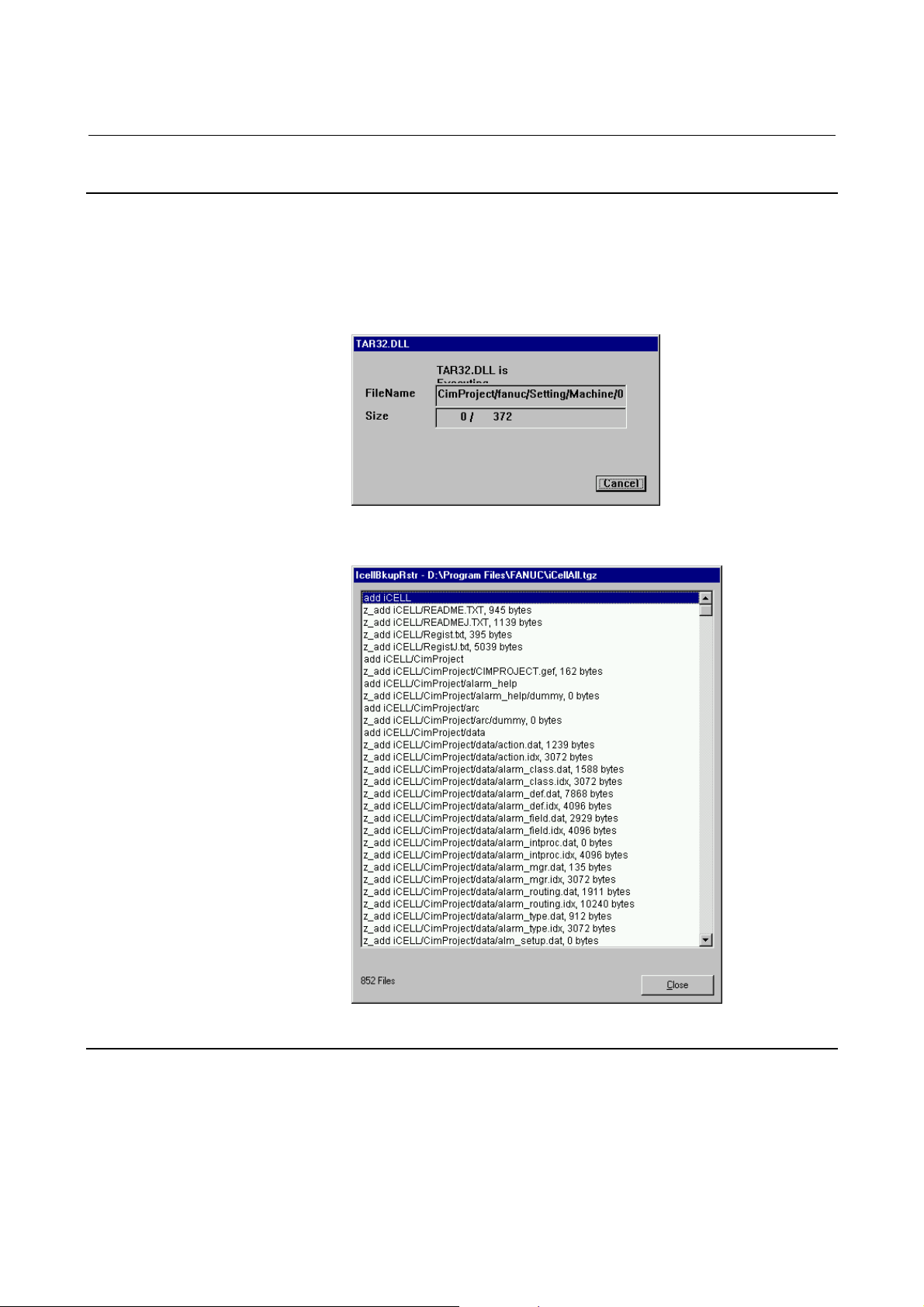
B-75074EN/01 INSTALLATION 5.BACKUP AND RESTORATION
5.1.4 Starting Backup
Clicking the <Backup> button starts backup.
If a backup file having the same name as specified now already exists,
a prompt message appears to ask whether you want to delete the
existing backup file and create a new one under the specified name.
During backup, the following window for indicating the backup file
name appears.
When backup is completed, the following window appears to display
a list of files backed up. Click the <Close> button.
5.1.5 Confirming the Contents of the Backup Archive File
After entering a backup archive file name in the [File Path] text box,
clicking the <Backup File List> button lists the information backed
up.
- 77 -
Page 98

5.BACKUP AND RESTORATION INSTALLATION B-75074EN/01
5.1.6 Saving the Backup Archive File
Save the backup archive file to an MO, CD-R, or floppy disk.
One floppy disk cannot hold the backup archive file unless it is
divided, because it is too large to fit on one floppy disk. The
iCellBkupRstr dialog box allows the backup archive file to be divided
so that it can be saved to more than one floppy file. Use the following
procedure.
Dividing and saving the backup archive file to floppy disks
(1) Specify a backup archive file to be divided.
In the [Backup/Restore File] frame, specify a backup archive file
in the [File Path] text box. A file can be selected by clicking the
small button at the right of the text box. At the end of backup,
the file name is automatically entered in the text box.
(2) Click the <Save with split> button to save the file to floppy
disks.
When the button is clicked, the number of floppy disks required
to hold the divided file is displayed. Get ready as many
formatted floppy disks as the quantity displayed.
(3) When you are prompted to insert a floppy disk, set a floppy disk
not write-protected into the drive, and click the <OK> button.
Label the floppy disk, for example, "Backup: All of i CELL
(1/4)".
(4) If a floppy disk has no enough free area, the following dialog
box appears. Select a desired process and continue backup.
- 78 -
Page 99

B-75074EN/01 INSTALLATION 5.BACKUP AND RESTORATION
5.2 RESTORATION
To restore data from the backup file, follow the procedure described
below.
5.2.1 Installing i CELL
If the PC is repaired, and Windows NT is re-installed in it, i CELL
must also be re-installed.
If you have not re-installed i CELL, start with the following
subsection.
5.2.2 Copying the Backup Archive File
Copy the backup archive file created as described in Section 5.1,
"Backup", back to the place where the file was initially stored.
If the file has been divided and saved to more than one floppy disk,
follow this procedure to copy it from the floppy disks to the hard disk.
Restoring the backup archive file divided and saved to more than one floppy
disk
(1) Set the first of the floppy disks that hold the backup archive file
into the floppy disk drive of the PC, and clock the <Restore to
HDD> button.
(2) When you are prompted to insert another floppy disk, set the
floppy disk with the correct sequence number, and click the
<OK> button.
5.2.3 Selecting Information to Be Restored
In the "Select Backup/Restore Directory" frame, select a desired
option button.
- 79 -
Page 100

5.BACKUP AND RESTORATION INSTALLATION B-75074EN/01
5.2.4 Starting Restoration
Clicking the <Restore> button starts restoration.
During restriction, the following window appears to display the name
of the files to be restored.
When restoration is completed, a window appears which lists the
restored files. Click the <Close> button to close the window.
5.2.5 Restoring NC Program Management Settings
If you re-installed i CELL, first restore i CELL by selecting "All of i
CELL" or "CimProject Only", and then restore NC program
management settings.
If you have not re-install i CELL, this process is not required.
1. Start File Explorer.
2. Display the bin directory under the directory where i CELL is
installed.
3. Double-click the PcfaRestore.bat file.
- 80 -
 Loading...