

Page 1

FANUC SYNCHRONOUS BUILT-IN SERVO MOTOR DiS series DESCRIPTIONS
1. Type of applied technical documents
Name
FANUC SYNCHRONOUS BUILT-IN SERVO MOTOR
DiS series DESCRIPTIONS
Spec. No/Edition
2. Summary of change
Group
Basic Function
Optional Function
Unit
Maintenance Parts
B-65332EN/03
New
Name/Outline
Add
Correct
Delete
FANUC SYNCHRONOUS BUILT-IN SERVO
MOTOR DiS series DESCRIPTIONS
/ Add DiS 120/600, DiS 500/1200,
DiS 1000/1000-385, DiS 1000/1000,
and DiS 5000/500
Add June 2015
Applicable
Date
Notice
Correction
Other
01 15.06.04 Y.Sugimoto Newly Designed
M.Aochi
FANUC SYNCHRONOUS BUILT-IN
Title
SERVO MOTOR DiS series
DESCRIPTIONS
Draw B-65332EN/03-06
Ed. Date Design Desctiption
FANUC CORPORATION
PAGE
1/34
Page 2

3. OUTLINE
The specifications of models in the following table are added to FANUC SYNCHRONOUS BUILT-IN SERVO MOTOR DiS series
DESCRIPTIONS (B-65332EN/03).
Model Ordering number
DiS 120/600
DiS 500/1200
DiS 1000/1000-385
DiS 1000/1000
DiS 5000/500(*)
*) DiS 5000/500 can be driven by only 400V power voltage. Other models can be driven by 200V/400V power voltage.
A06B-0493-B400
A06B-0495-B421
A06B-0499-B420
A06B-0496-B320
A06B-0488-B430
4. CAUTION
FANUC SYNCHRONOUS BUILT-IN SERVO MOTOR DiS series DESCRIPTIONS (B-65332EN/03) describes important
information such as safety precautions for protecting the user and preventing damage to the machine, considerations for
designing the machine, and start-up procedure. Be sure to read it in conjunction with this manual.
5. System Requirements
[CNC, Servo Software series and editions]
The following table lists CNC and servo software series and edition for driving the motors described in this report.
CNC
Series 30i/31i/32i/35i-B
As of June 2015, the motors described in this report can’t be driven by CNC and servo software series and edition not
mentioned above.
Series Editions
90J0 07.0 and subsequent editions
90K0 05.0 and subsequent editions (scheduled)
Servo Software
[Servo amplifier]
The following table lists the servo amplifiers applicable for each model. For the detail of Servo Amplifier, please refer to “FANUC
SERVO AMPLIFIER αi-B series DESCRIPTIONS (B-65412EN/01)” and “Addition of Level-up αi-B series servo amplifier
(B-65412EN/01-19)”.
Input Power Voltage: 200V
Model (Ordering number)
αiSV 80-B
αiSV 80-B
DiS 120/600 (A06B-0493-B400)
DiS 500/1200 (A06B-0495-B421) αiSV 360-B
DiS 1000/1000-385 (A06B-0499-B420) αiSV 360-B
DiS 1000/1000 (A06B-0496-B320) αiSV 360-B
*) A06B-6240-H109 can’t be used.
αiSV 40/80-B
αiSV 80/80-B
αiSV 80/160-B
Applicable servo amplifier
Name Ordering number
A06B-6240-H105
A06B-6240-H125
A06B-6240-H208
A06B-6240-H209
A06B-6240-H210
A06B-6240-H129(*)
A06B-6240-H129(*)
A06B-6240-H129(*)
Title
01 15.06.04 Y.Sugimoto Newly Designed
Ed. Date Design Desctiption
Draw B-65332EN/03-06
M.Aochi
FANUC CORPORATION
FANUC SYNCHRONOUS BUILT-IN
SERVO MOTOR DiS series
DESCRIPTIONS
PAGE
2/34
Page 3

Applicable
servo
amplifier
Name
Ordering number
Sub Module SM
Name
Ordering number
Input Power Voltage: 400V
Model (Ordering number)
αiSV 80HV-B
αiSV 80HV-B
DiS 120/600 (A06B-0493-B400)
DiS 500/1200 (A06B-0495-B421) αiSV 360HV-B
DiS 1000/1000-385 (A06B-0499-B420) αiSV 360HV-B
DiS 1000/1000 (A06B-0496-B320) αiSV 360HV-B
DiS 5000/500 (A06B-0488-B430) αiSV 540HV-B
*1) A06B-6290-H109 can’t be used.
*2) A06B-6290-H110 can’t be used.
In driving the motor listed the following table, Sub Module SM is required. For the detail of Sub Module SM, please also refer to
“FANUC SERVO AMPLIFIER αi-B series DESCRIPTIONS (B-65412EN/01)” and “Addition of Level-up αi-B series servo
amplifier (B-65412EN/01-19)”.
DB module isn’t required.
Model (Ordering number)
DiS 500/1200 (A06B-0495-B421)
DiS 1000/1000-385 (A06B-0499-B420)
DiS 1000/1000 (A06B-0496-B320)
DiS 5000/500 (A06B-0488-B430)
αiSV 80HVL-B
αiSV 40/80HV-B
αiSV 80/80HV-B
SSM-200 A06B-6111-H404
A06B-6290-H105
A06B-6290-H125
A06B-6290-H175
A06B-6290-H208
A06B-6290-H209
A06B-6290-H129(*1)
A06B-6290-H129(*1)
A06B-6290-H129(*1)
A06B-6290-H130(*2)
[Rotary encoder]
FANUC recommends absolute rotary encoders the resolution per revolution of which is represented by a 2n (binary number) and that
supports the FANUC serial interface.
Example) αiCZ 512A, αiCZ 1024A (manufactured by FANUC), RCN2390F (manufactured by HEIDENHAIN)
αiCZ 768A and rotary encoders the resolution per revolution of which is not represented by a 2n number (for example, 1,800,000rev)
connected to Synchronous Built-in Servo Motor Position Detection Circuit must be used with the rotary encoder parameters consulted
by FANUC. And please be sure to check the maximum speed of your encoder.
[Motor ID No.]
Set 418 as motor ID number. As parameters of the motor is not loaded automatically, it is necessary for customers to set the
parameters according to “15. Parameters”.
[Other]
• All of the motors described in this report can be used with liquid cooling only.
• DiS 500/1200, DiS 1000/1000-385, DiS 1000/1000, and DiS 5000/500 can be driven by HRV3 control only. For the detail of
HRV3, please refer to “Parameter Manual (B-65270EN/08)”
• CNC to be used with DiS series motors must include optional function for “Pole Position Detection Function”.
01 15.06.04 Y.Sugimoto Newly Designed
Title
Draw B-65332EN/03-06
M.Aochi
FANUC SYNCHRONOUS BUILT-IN
SERVO MOTOR DiS series
DESCRIPTIONS
Ed. Date Design Desctiption
FANUC CORPORATION
PAGE
3/34
Page 4

max
c
max
s
max
max
Torque(Nm)
6. Data Sheets
6.1 Input Power Voltage: 200V
DiS 120/600 (A06B-0493-B400) 200V Used with liquid cooling only
Torque-speed graph Overload duty characteristic
duty [%]
100%
90%
80%
70%
60%
50%
40%
30%
20%
10%
0%
1 10 100
- V
Pr kW
Tr Nm
Nr min-1
Tc
Ts
T
T
Nm
Nm
- min-1
N
min-1
Ic
Is
I
Arms
Arms
Kt Nm/Arms
Ra Ω
tt min.
- W
Q L/min.
Jm kgm2
Ws kg
Wr kg
P Pole
- Ap
300
250
200
150
100
Intermittent
operation
Continuous
operation
50
0
0 200 400 600
Speed(min-1)
Specifications
Items Symbol Unit Specification
Input power voltage
Rated output (*)
Rated torque (*)
Rated speed
Continuous torque (*)
Maximum torque (*)
At low speed
At a stop
At low speed
At a stop
Upper speed for the maximum torque
Maximum speed
Continuous current (*)
At low speed
At a stop
Maximum current
Torque constant(*)
Winding resistance (between terminals) (*)
Thermal time constant
Required cooling capacity
Flow rate
Moment of inertia of rotor
Mass
Stator
Rotor
Number of poles
Maximum current of the applicable amplifier
120%
140%
160%
180%
MAX
ON time [sec]
200
3.6
115
300
118
101
240
240
200
600
19.3
15.8
42.4
6.5
2.47
2.4
2800
15
0.013
14
5.4
24
80
• (*): Indicates the standard value at a temperature of 20°C. (±10%)
• The values may vary depending on the ambient temperature, series and edition of servo software, parameters, input power supply
voltage, servo amplifier specifications, individual motor difference, and others.
• The values are subject to change without notice.
• For the description of each item, see Subsection 1.2.1, “Terms” of “FANUC SYNCHRONOUS BUILT-IN SERVO MOTOR DiS series
DESCRIPTIONS (B-65332EN/03)”.
• The overload duty characteristic is calculated based on the thermal characteristic of the running motor at low speed. The on time may
become shorter at 0 [min-1]. And it isn’t possible to consider the propriety of the driving pattern including high speed running by using the
overload duty characteristic. In that case, please contact us and send the pattern.
• This motor can be used with liquid cooling only.
01 15.06.04 Y.Sugimoto Newly Designed
Ed. Date Design Desctiption
Title
Draw B-65332EN/03-06
M.Aochi
FANUC CORPORATION
FANUC SYNCHRONOUS BUILT-IN
SERVO MOTOR DiS series
DESCRIPTIONS
PAGE
4/34
Page 5

max
c
max
s
max
max
Torque(Nm)
DiS 500/1200 (A06B-0495-B421) 200V Used with liquid cooling only
Torque-speed graph Overload duty characteristic
duty [%]
100%
90%
80%
70%
60%
50%
40%
30%
20%
10%
0%
1 10 100
- V
Pr kW
Tr Nm
Nr min-1
Tc
Ts
T
T
Nm
Nm
- min-1
N
min-1
Ic
Is
I
Arms
Arms
Kt Nm/Arms
Ra Ω
tt min.
- W
Q L/min.
Jm kgm2
Ws kg
Wr kg
P Pole
- Ap
1200
1000
Intermittent
800
operation
600
400
Continuous
200
operation
0
0 400 800 1200
Speed(min-1)
Specifications
Input power voltage
Rated output (*)
Rated torque (*)
Rated speed
Continuous torque (*)
Maximum torque (*)
Upper speed for the maximum torque
Maximum speed
Continuous current (*)
Maximum current
Torque constant(*)
Winding resistance (between terminals) (*)
Thermal time constant
Required cooling capacity
Moment of inertia of rotor
Mass
Number of poles
Maximum current of the applicable amplifier
Items Symbol Unit Specification
At low speed
At a stop
At low speed
At a stop
At low speed
At a stop
Flow rate
Stator
Rotor
120%
140%
160%
180%
MAX
ON time [sec]
200
12.1
192
600
550
430
1000
600
320
1200
126
109
255
4.6
0.107
2.3
3100
15
0.17
24
15
48
360
• (*): Indicates the standard value at a temperature of 20°C. (±10%)
• The values may vary depending on the ambient temperature, series and edition of servo software, parameters, input power supply
voltage, servo amplifier specifications, individual motor difference, and others.
• The values are subject to change without notice.
• For the description of each item, see Subsection 1.2.1, “Terms” of “FANUC SYNCHRONOUS BUILT-IN SERVO MOTOR DiS series
DESCRIPTIONS (B-65332EN/03)”.
• The overload duty characteristic is calculated based on the thermal characteristic of the running motor at low speed. The on time may
become shorter at 0 [min-1]. And it isn’t possible to consider the propriety of the driving pattern including high speed running by using the
overload duty characteristic. In that case, please contact us and send the pattern.
• Maximum torque is limited to 600Nm at less than 20 [min-1].
• This motor can be used with liquid cooling only.
• This motor can be driven with HRV3 only.
01 15.06.04 Y.Sugimoto Newly Designed
Ed. Date Design Desctiption
Title
Draw B-65332EN/03-06
M.Aochi
FANUC CORPORATION
FANUC SYNCHRONOUS BUILT-IN
SERVO MOTOR DiS series
DESCRIPTIONS
PAGE
5/34
Page 6

max
c
max
s
max
max
Torque(Nm)
DiS 1000/1000-385 (A06B-0499-B420) 200V Used with liquid cooling only
Torque-speed graph Overload duty characteristic
duty [%]
100%
90%
80%
70%
60%
50%
40%
30%
20%
10%
0%
1 10 100
- V
Pr kW
Tr Nm
Nr min-1
Tc
Ts
T
T
Nm
Nm
- min-1
N
min-1
Ic
Is
I
Arms
Arms
Kt Nm/Arms
Ra Ω
tt min.
- W
Q L/min.
Jm kgm2
Ws kg
Wr kg
P Pole
- Ap
2000
1500
Intermittent
operation
1000
500
Continuous
operation
0
0 100 200 300 400 500
Speed(min-1)
Specifications
Input power voltage
Rated output (*)
Rated torque (*)
Continuous torque (*)
Maximum torque (*)
Upper speed for the maximum torque
Maximum speed
Continuous current (*)
Maximum current
Torque constant(*)
Winding resistance (between terminals) (*)
Thermal time constant
Required cooling capacity
Moment of inertia of rotor
Mass
Number of poles
Maximum current of the applicable amplifier
Items Symbol Unit Specification
Rated speed
At low speed
At a stop
At low speed
At a stop
At low speed
At a stop
Flow rate
Stator
Rotor
120%
140%
160%
MAX
ON time [sec]
200
17.5
334
500
1000
890
1600
1200
140
500
120
107
212
9.1
0.157
4.0
4500
15
0.39
42
21
56
360
• (*): Indicates the standard value at a temperature of 20°C. (±10%)
• The values may vary depending on the ambient temperature, series and edition of servo software, parameters, input power supply
voltage, servo amplifier specifications, individual motor difference, and others.
• The values are subject to change without notice.
• For the description of each item, see Subsection 1.2.1, “Terms” of “FANUC SYNCHRONOUS BUILT-IN SERVO MOTOR DiS series
DESCRIPTIONS (B-65332EN/03)”.
• The overload duty characteristic is calculated based on the thermal characteristic of the running motor at low speed. The on time may
become shorter at 0 [min-1]. And it isn’t possible to consider the propriety of the driving pattern including high speed running by using the
overload duty characteristic. In that case, please contact us and send the pattern.
• Maximum torque is limited to 1200Nm at less than 18 [min-1].
• This motor can be used with liquid cooling only.
• This motor can be driven with HRV3 only.
01 15.06.04 Y.Sugimoto Newly Designed
Ed. Date Design Desctiption
Title
Draw B-65332EN/03-06
M.Aochi
FANUC CORPORATION
FANUC SYNCHRONOUS BUILT-IN
SERVO MOTOR DiS series
DESCRIPTIONS
PAGE
6/34
Page 7

max
c
max
s
max
max
Torque(Nm)
DiS 1000/1000 (A06B-0496-B320) 200V Used with liquid cooling only
Torque-speed graph Overload duty characteristic
2000
1500
1000
500
Continuous
Intermittent
operation
operation
0
0 100 200 300 400 500
Speed(min-1)
Specifications
Items Symbol Unit Specification
Input power voltage
Rated output (*)
Rated torque (*)
Rated speed
Continuous torque (*)
Maximum torque (*)
At low speed
At a stop
At low speed
At a stop
Upper speed for the maximum torque
Maximum speed
Continuous current (*)
At low speed
At a stop
Maximum current
Torque constant(*)
Winding resistance (between terminals) (*)
Thermal time constant
Required cooling capacity
Flow rate
Moment of inertia of rotor
Mass
Stator
Rotor
Number of poles
Maximum current of the applicable amplifier
duty [%]
100%
90%
80%
70%
60%
50%
40%
30%
20%
10%
0%
1 10 100
- V
Pr kW
Tr Nm
Nr min-1
Tc
Ts
T
T
Nm
Nm
- min-1
N
min-1
Ic
Is
I
Arms
Arms
Kt Nm/Arms
Ra Ω
tt min.
- W
Q L/min.
Jm kgm2
Ws kg
Wr kg
P Pole
- Ap
120%
140%
160%
MAX
ON time [sec]
200
17.5
333
500
960
870
1500
1150
160
500
121
106
212
8.7
0.135
4.0
3500
15
0.53
48
20
64
360
• (*): Indicates the standard value at a temperature of 20°C. (±10%)
• The values may vary depending on the ambient temperature, series and edition of servo software, parameters, input power supply
voltage, servo amplifier specifications, individual motor difference, and others.
• The values are subject to change without notice.
• For the description of each item, see Subsection 1.2.1, “Terms” of “FANUC SYNCHRONOUS BUILT-IN SERVO MOTOR DiS series
DESCRIPTIONS (B-65332EN/03)”.
• The overload duty characteristic is calculated based on the thermal characteristic of the running motor at low speed. The on time may
become shorter at 0 [min-1]. And it isn’t possible to consider the propriety of the driving pattern including high speed running by using the
overload duty characteristic. In that case, please contact us and send the pattern.
• Maximum torque is limited to 1150Nm at less than 17 [min-1].
• This motor can be used with liquid cooling only.
• This motor can be driven with HRV3 only.
01 15.06.04 Y.Sugimoto Newly Designed
Ed. Date Design Desctiption
Title
Draw B-65332EN/03-06
M.Aochi
FANUC CORPORATION
FANUC SYNCHRONOUS BUILT-IN
SERVO MOTOR DiS series
DESCRIPTIONS
PAGE
7/34
Page 8

max
c
max
s
max
max
Torque(Nm)
6.2 Input Power Voltage: 400V
DiS 120/600 (A06B-0493-B400) 400V Used with liquid cooling only
Torque-speed graph Overload duty characteristic
duty [%]
100%
90%
80%
70%
60%
50%
40%
30%
20%
10%
0%
1 10 100
- V
Pr kW
Tr Nm
Nr min-1
Tc
Ts
T
T
Nm
Nm
- min-1
N
min-1
Ic
Is
I
Arms
Arms
Kt Nm/Arms
Ra Ω
tt min.
- W
Q L/min.
Jm kgm2
Ws kg
Wr kg
P Pole
- Ap
300
250
200
150
Intermittent
operation
100
Continuous
50
operation
0
0 200 400 600
Speed(min-1)
Specifications
Items Symbol Unit Specification
Input power voltage
Rated output (*)
Rated torque (*)
Rated speed
Continuous torque (*)
Maximum torque (*)
At low speed
At a stop
At low speed
At a stop
Upper speed for the maximum torque
Maximum speed
Continuous current (*)
At low speed
At a stop
Maximum current
Torque constant(*)
Winding resistance (between terminals) (*)
Thermal time constant
Required cooling capacity
Flow rate
Moment of inertia of rotor
Mass
Stator
Rotor
Number of poles
Maximum current of the applicable amplifier
120%
140%
160%
180%
MAX
ON time [sec]
400
5.2
83
600
118
101
240
240
520
600
19.3
15.8
42.4
6.5
2.47
2.4
2800
15
0.013
14
5.4
24
80
• (*): Indicates the standard value at a temperature of 20°C. (±10%)
• The values may vary depending on the ambient temperature, series and edition of servo software, parameters, input power supply
voltage, servo amplifier specifications, individual motor difference, and others.
• The values are subject to change without notice.
• For the description of each item, see Subsection 1.2.1, “Terms” of “FANUC SYNCHRONOUS BUILT-IN SERVO MOTOR DiS series
DESCRIPTIONS (B-65332EN/03)”.
• The overload duty characteristic is calculated based on the thermal characteristic of the running motor at low speed. The on time may
become shorter at 0 [min-1]. And it isn’t possible to consider the propriety of the driving pattern including high speed running by using the
overload duty characteristic. In that case, please contact us and send the pattern.
• This motor can be used with liquid cooling only.
01 15.06.04 Y.Sugimoto Newly Designed
Ed. Date Design Desctiption
Title
Draw B-65332EN/03-06
M.Aochi
FANUC CORPORATION
FANUC SYNCHRONOUS BUILT-IN
SERVO MOTOR DiS series
DESCRIPTIONS
PAGE
8/34
Page 9

max
c
max
s
max
max
Torque(Nm)
DiS 500/1200 (A06B-0495-B421) 400V Used with liquid cooling only
Torque-speed graph Overload duty characteristic
duty [%]
100%
90%
80%
70%
60%
50%
40%
30%
20%
10%
0%
1 10 100
- V
Pr kW
Tr Nm
Nr min-1
Tc
Ts
T
T
Nm
Nm
- min-1
N
min-1
Ic
Is
I
Arms
Arms
Kt Nm/Arms
Ra Ω
tt min.
- W
Q L/min.
Jm kgm2
Ws kg
Wr kg
P Pole
- Ap
1200
1000
800
Intermittent
operation
600
400
Continuous
200
operation
0
0 400 800 1200
Speed(min-1)
Specifications
Input power voltage
Rated output (*)
Rated torque (*)
Continuous torque (*)
Maximum torque (*)
Upper speed for the maximum torque
Maximum speed
Continuous current (*)
Maximum current
Torque constant(*)
Winding resistance (between terminals) (*)
Thermal time constant
Required cooling capacity
Moment of inertia of rotor
Mass
Number of poles
Maximum current of the applicable amplifier
Items Symbol Unit Specification
Rated speed
At low speed
At a stop
At low speed
At a stop
At low speed
At a stop
Flow rate
Stator
Rotor
120%
140%
160%
180%
MAX
ON time [sec]
400
12.1
192
600
550
430
1000
600
520
1200
126
109
255
4.6
0.107
2.3
3100
15
0.17
24
15
48
360
• (*): Indicates the standard value at a temperature of 20°C. (±10%)
• The values may vary depending on the ambient temperature, series and edition of servo software, parameters, input power supply
voltage, servo amplifier specifications, individual motor difference, and others.
• The values are subject to change without notice.
• For the description of each item, see Subsection 1.2.1, “Terms” of “FANUC SYNCHRONOUS BUILT-IN SERVO MOTOR DiS series
DESCRIPTIONS (B-65332EN/03)”.
• The overload duty characteristic is calculated based on the thermal characteristic of the running motor at low speed. The on time may
become shorter at 0 [min-1]. And it isn’t possible to consider the propriety of the driving pattern including high speed running by using the
overload duty characteristic. In that case, please contact us and send the pattern.
• Maximum torque is limited to 600Nm at less than 20 [min-1].
• This motor can be used with liquid cooling only.
• This motor can be driven with HRV3 only.
01 15.06.04 Y.Sugimoto Newly Designed
Ed. Date Design Desctiption
Title
Draw B-65332EN/03-06
M.Aochi
FANUC CORPORATION
FANUC SYNCHRONOUS BUILT-IN
SERVO MOTOR DiS series
DESCRIPTIONS
PAGE
9/34
Page 10

max
c
max
s
max
max
Torque(Nm)
DiS 1000/1000-385 (A06B-0499-B420) 400V Used with liquid cooling only
Torque-speed graph Overload duty characteristic
duty [%]
100%
90%
80%
70%
60%
50%
40%
30%
20%
10%
0%
1 10 100
ON time [sec]
2000
1500
1000
Intermittent
operation
500
Continuous
operation
0
0 250 500 750 1000
Speed(min-1)
Specifications
Items Symbol Unit Specification
Input power voltage
Rated output (*)
Rated torque (*)
Rated speed
Continuous torque (*)
Maximum torque (*)
At low speed
At a stop
At low speed
At a stop
Upper speed for the maximum torque
Maximum speed
Continuous current (*)
At low speed
At a stop
Maximum current
Torque constant(*)
Winding resistance (between terminals) (*)
Thermal time constant
Required cooling capacity
Flow rate
Moment of inertia of rotor
Mass
Stator
Rotor
Number of poles
Maximum current of the applicable amplifier
- V
Pr kW
Tr Nm
Nr min-1
Tc
Ts
T
T
Nm
Nm
- min-1
N
min-1
Ic
Is
I
Arms
Arms
Kt Nm/Arms
Ra Ω
tt min.
- W
Q L/min.
Jm kgm2
Ws kg
Wr kg
P Pole
- Ap
400
17.5
334
500
1000
890
1600
1200
350
1000
120
107
212
0.157
4500
0.387
360
120%
140%
160%
MAX
9.1
4.0
15
42
21
56
• (*): Indicates the standard value at a temperature of 20°C. (±10%)
• The values may vary depending on the ambient temperature, series and edition of servo software, parameters, input power supply
voltage, servo amplifier specifications, individual motor difference, and others.
• The values are subject to change without notice.
• For the description of each item, see Subsection 1.2.1, “Terms” of “FANUC SYNCHRONOUS BUILT-IN SERVO MOTOR DiS series
DESCRIPTIONS (B-65332EN/03)”.
• The overload duty characteristic is calculated based on the thermal characteristic of the running motor at low speed. The on time may
become shorter at 0 [min-1]. And it isn’t possible to consider the propriety of the driving pattern including high speed running by using the
overload duty characteristic. In that case, please contact us and send the pattern.
• Maximum torque is limited to 1200Nm at less than 18 [min-1].
• This motor can be used with liquid cooling only.
• This motor can be driven with HRV3 only.
01 15.06.04 Y.Sugimoto Newly Designed
Ed. Date Design Desctiption
Title
Draw B-65332EN/03-06
M.Aochi
FANUC CORPORATION
FANUC SYNCHRONOUS BUILT-IN
SERVO MOTOR DiS series
DESCRIPTIONS
PAGE
10/34
Page 11

max
c
max
s
max
max
Torque(Nm)
DiS 1000/1000 (A06B-0496-B320) 400V Used with liquid cooling only
Torque-speed graph Overload duty characteristic
duty [%]
100%
90%
80%
70%
60%
50%
40%
30%
20%
10%
0%
1 10 100
- V
Pr kW
Tr Nm
Nr min-1
Tc
Ts
T
T
Nm
Nm
- min-1
N
min-1
Ic
Is
I
Arms
Arms
Kt Nm/Arms
Ra Ω
tt min.
- W
Q L/min.
Jm kgm2
Ws kg
Wr kg
P Pole
- Ap
2000
1500
1000
Intermittent
operation
500
Continuous
operation
0
0 250 500 750 1000
Speed(min-1)
Specifications
Input power voltage
Rated output (*)
Rated torque (*)
Rated speed
Continuous torque (*)
Maximum torque (*)
Upper speed for the maximum torque
Maximum speed
Continuous current (*)
Maximum current
Torque constant(*)
Winding resistance (between terminals) (*)
Thermal time constant
Required cooling capacity
Moment of inertia of rotor
Mass
Number of poles
Maximum current of the applicable amplifier
Items Symbol Unit Specification
At low speed
At a stop
At low speed
At a stop
At low speed
At a stop
Flow rate
Stator
Rotor
120%
140%
160%
MAX
ON time [sec]
400
17.5
333
500
960
870
1500
1150
280
1000
121
106
212
8.7
0.135
4.0
3500
15
0.53
48
20
64
360
• (*): Indicates the standard value at a temperature of 20°C. (±10%)
• The values may vary depending on the ambient temperature, series and edition of servo software, parameters, input power supply
voltage, servo amplifier specifications, individual motor difference, and others.
• The values are subject to change without notice.
• For the description of each item, see Subsection 1.2.1, “Terms” of “FANUC SYNCHRONOUS BUILT-IN SERVO MOTOR DiS series
DESCRIPTIONS (B-65332EN/03)”.
• The overload duty characteristic is calculated based on the thermal characteristic of the running motor at low speed. The on time may
become shorter at 0 [min-1]. And it isn’t possible to consider the propriety of the driving pattern including high speed running by using the
overload duty characteristic. In that case, please contact us and send the pattern.
• Maximum torque is limited to 1150Nm at less than 17 [min-1].
• This motor can be used with liquid cooling only.
• This motor can be driven with HRV3 only.
01 15.06.04 Y.Sugimoto Newly Designed
Ed. Date Design Desctiption
Title
Draw B-65332EN/03-06
M.Aochi
FANUC CORPORATION
FANUC SYNCHRONOUS BUILT-IN
SERVO MOTOR DiS series
DESCRIPTIONS
PAGE
11/34
Page 12

max
c
max
s
max
max
Torque(Nm)
DiS 5000/500 (A06B-0488-B430) 400V Used with liquid cooling only
Torque-speed graph
10000
8000
6000
4000
2000
0
0 100 200 300 400 500
Speed(min-1)
Specifications
Items Symbol Unit Specification
Input power voltage
Rated output (*)
Rated torque (*)
Rated speed
Continuous torque (*)
Maximum torque (*)
Upper speed for the maximum torque
Maximum speed
Continuous current (*)
Maximum current
Torque constant(*)
Winding resistance (between terminals) (*)
Thermal time constant
Required cooling capacity
Flow rate
Moment of inertia of rotor
Mass
Number of poles
Maximum current of the applicable amplifier
At low speed
At a stop
At low speed
At a stop
At low speed
At a stop
Stator
Rotor
Overload duty characteristic
100%
90%
80%
70%
60%
50%
40%
duty [%]
30%
20%
10%
0%
1 10 100
- V
Pr kW
Tr Nm
Nr min-1
Tc
Ts
T
T
Nm
Nm
- min-1
N
min-1
Ic
Is
I
Arms
Arms
Kt Nm/Arms
Ra Ω
tt min.
- W
Q L/min.
Jm kgm2
Ws kg
Wr kg
P Pole
- Ap
120%
140%
160%
180%
MAX
ON time [sec]
400
39.0
1240
300
4500
4000
8000
6000
60
500
151
134
350
32
0.169
7.3
6800
15
6.87
160
70
128
540
• (*): Indicates the standard value at a temperature of 20°C. (±10%)
• The values may vary depending on the ambient temperature, series and edition of servo software, parameters, input power supply
voltage, servo amplifier specifications, individual motor difference, and others.
• The values are subject to change without notice.
• For the description of each item, see Subsection 1.2.1, “Terms” of “FANUC SYNCHRONOUS BUILT-IN SERVO MOTOR DiS series
DESCRIPTIONS (B-65332EN/03)”.
• The overload duty characteristic is calculated based on the thermal characteristic of the running motor at low speed. The on time may
become shorter at 0 [min-1]. And it isn’t possible to consider the propriety of the driving pattern including high speed running by using the
overload duty characteristic. In that case, please contact us and send the pattern.
• Maximum torque is limited to 6000Nm at less than 12 [min-1].
• This motor can be used with liquid cooling only.
• This motor can be driven with HRV3 only.
01 15.06.04 Y.Sugimoto Newly Designed
Ed. Date Design Desctiption
Title
Draw B-65332EN/03-06
M.Aochi
FANUC CORPORATION
FANUC SYNCHRONOUS BUILT-IN
SERVO MOTOR DiS series
DESCRIPTIONS
PAGE
12/34
Page 13
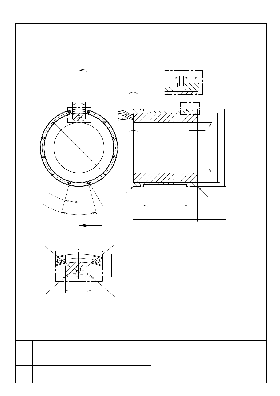
7. External dimensions
Tolerances without individual indications must conform to “JIS B 0405 General tolerances (m)”.
DiS 120/600 (A06B-0493-B400)
[Stator dimensions]
(Slit width)
30
1.5
(Slit depth)
A
2
O
1
7
0
Detail of B:Groove for O-ring
184.8
B
2
116.5min.
161
O
O
180 f8
O
1
5
°
12-M6
Depth13
3
0
°
Detail of A:Cable output area
R
5
(both sides)
5
R
27
5
R
30
R
C1
C
1
100
(Groove)
150 ±0.2
5
Title
01 15.06.04 Y.Sugimoto Newly Designed
Ed. Date Design Desctiption
Draw B-65332EN/03-06
M.Aochi
FANUC CORPORATION
FANUC SYNCHRONOUS BUILT-IN
SERVO MOTOR DiS series
DESCRIPTIONS
PAGE
13/34
Page 14

[Rotor dimensions]
[Assembly dimensions]
Positive
direction of
motor rotation
°
0
4
16-φ9 Depth7.0
M8 Depth15
Pitch 20deg. (both sides)
4
0
°
110
( * )
75 H8
O
9
°
0
2
4
0
°
5
2
5
O
120
(* Width of 110mm from both ends except for the 5.0mm)
Coolant In
30
Coolant Out
30
01 15.06.04 Y.Sugimoto Newly Designed
Ed. Date Design Desctiption
M.Aochi
15 ±1
FANUC SYNCHRONOUS BUILT-IN
Title
SERVO MOTOR DiS series
DESCRIPTIONS
Draw B-65332EN/03-06
FANUC CORPORATION
PAGE
14/34
Page 15

DiS 500/1200 (A06B-0495-B421)
[Stator dimensions]
30
(Slit width)
Detail of B:Groove for O-ring
4.8 18
1.5
(Slit depth)
B
A
2
2
238.5min.
291
O
O
3
0
0
O
310 f8
O
7
.
5
°
1
5
°
24-M6
Depth13
(both sides)
Detail of A:Cable output area
R
5
5
R
31
5
R
50
R
5
C1
C
1
100
(Groove)
150 ±0.2
Title
01 15.06.04 Y.Sugimoto Newly Designed
Ed. Date Design Desctiption
Draw B-65332EN/03-06
M.Aochi
FANUC CORPORATION
FANUC SYNCHRONOUS BUILT-IN
SERVO MOTOR DiS series
DESCRIPTIONS
PAGE
15/34
Page 16

[Rotor dimensions]
[Assembly dimensions]
116
φ6H8 Depth12
(both sides)
2-φ6.6 Depth7.5
( * )
O
2
0
5
185 H8
O
101
7.5
7
.
5
°
1
5
°
7.5
24-φ11 Depth7.5
M10 Depth17
(both sides)
(* Width of 101mm from both ends except for the 7.5mm)
Coolant In
Coolant Out
30 30
Positive
direction of
motor rotation
01 15.06.04 Y.Sugimoto Newly Designed
Ed. Date Design Desctiption
M.Aochi
17 ±1
FANUC SYNCHRONOUS BUILT-IN
Title
SERVO MOTOR DiS series
DESCRIPTIONS
Draw B-65332EN/03-06
FANUC CORPORATION
PAGE
16/34
Page 17

DiS 1000/1000-385 (A06B-0499-B420)
[Stator dimensions]
30
(Slit width)
A
O
Detail of B:Groove for O-ring
7.5 19.5
1.5
(Slit depth)
B
5 5
296.5min.
361
O
3
7
0
O
385 f8
O
7
.
5
°
1
5
°
24-M6
Depth13
(both sides)
Detail of A:Cable output area
R
5
5
R
80
1
C
C
1
100
(Groove)
160 ±0.2
5
R
39
R
5
Title
01 15.06.04 Y.Sugimoto Newly Designed
Ed. Date Design Desctiption
Draw B-65332EN/03-06
M.Aochi
FANUC CORPORATION
FANUC SYNCHRONOUS BUILT-IN
SERVO MOTOR DiS series
DESCRIPTIONS
PAGE
17/34
Page 18

[Rotor dimensions]
[Assembly dimensions]
O
121
( * )
2
6
5
110
5.5
5.5
240 H8
O
24-O11 Depth7.5
M10 Depth17
(both sides)
(* Width of 110mm from both ends except for the 5.5mm)
Coolant In
Coolant Out
35 35
Positive
direction of
motor rotation
01 15.06.04 Y.Sugimoto Newly Designed
M.Aochi
19.5 ±1
FANUC SYNCHRONOUS BUILT-IN
Title
SERVO MOTOR DiS series
DESCRIPTIONS
Draw B-65332EN/03-06
Ed. Date Design Desctiption
FANUC CORPORATION
PAGE
18/34
Page 19

DiS 1000/1000 (A06B-0496-B320)
[Stator dimensions]
30
(Slit width)
A
O
Detail of B:Groove for O-ring
7.5 19.5
1.5
(Slit depth)
B
5 5
354.5min.
425
O
4
3
6
O
455 f8
O
1
5
°
3
0
°
12-M8
Depth15
(both sides)
Detail of A:Cable output area
R
5
5
R
45
5
R
R
5
80
1
C
C
1
70
(Groove)
130 ±0.2
Title
01 15.06.04 Y.Sugimoto Newly Designed
Ed. Date Design Desctiption
Draw B-65332EN/03-06
M.Aochi
FANUC CORPORATION
FANUC SYNCHRONOUS BUILT-IN
SERVO MOTOR DiS series
DESCRIPTIONS
PAGE
19/34
Page 20

[Rotor dimensions]
[Assembly dimensions]
2-φ9 Depth10
φ8H8 Depth16
(both sides)
( * )
295 H8
O
O
91
3
1
5
71
10 10
1
1
.
2
5
2
°
2
.
5
°
(* Width of 71mm from both ends except for the 10mm)
Coolant In
16-φ14 Depth10
M12 Depth20
(both sides)
Coolant Out
35 35
Positive
direction of
motor rotation
01 15.06.04 Y.Sugimoto Newly Designed
Ed. Date Design Desctiption
M.Aochi
19.5 ±1
FANUC SYNCHRONOUS BUILT-IN
Title
SERVO MOTOR DiS series
DESCRIPTIONS
Draw B-65332EN/03-06
FANUC CORPORATION
PAGE
20/34
Page 21

DiS 5000/500 (A06B-0488-B430)
[Stator dimensions]
30
(Slit width)
Detail of B:Groove for O-ring
29.57.5
φ10H8 Depth20
A
(Slit depth)
5
1.5
(both sides)
B
5
659.5min.
755
O
O
7
7
4
O
795 f8
O
1
1
.
2
5
2
°
2
.
5
°
16-M12
Depth20
(both sides)
Detail of A:Cable output area
R
5
5
R
62
5
R
80
R
5
1
C
C
1
100
(Groove)
180 ±0.2
Title
01 15.06.04 Y.Sugimoto Newly Designed
Ed. Date Design Desctiption
Draw B-65332EN/03-06
M.Aochi
FANUC CORPORATION
FANUC SYNCHRONOUS BUILT-IN
SERVO MOTOR DiS series
DESCRIPTIONS
PAGE
21/34
Page 22

[Rotor dimensions]
[Assembly dimensions]
2-φ11 Depth20
141
φ10H8 Depth20
(both sides)
( * )
O
6
1
6
101
590 H8
O
2020
9
°
1
8
°
(* Width of 101mm from both ends except for the 20mm)
Coolant In
20-φ18 Depth20
M16 Depth25
(both sides)
Coolant Out
45 45
Positive
direction of
motor rotation
01 15.06.04 Y.Sugimoto Newly Designed
Ed. Date Design Desctiption
M.Aochi
19.5 ±1
FANUC SYNCHRONOUS BUILT-IN
Title
SERVO MOTOR DiS series
DESCRIPTIONS
Draw B-65332EN/03-06
FANUC CORPORATION
PAGE
22/34
Page 23

Red, White,
Red, White,
Red, White,
8. Specifications of Power Line
Model (Ordering number) Color
Conductor size
Cross-
section
(mm2)
AWG
size
Outer diameter
(mm)
Minimum
bending radius
(mm)
DiS 120/600 (A06B-0493-B400)
DiS 500/1200 (*) (A06B-0495-B421)
DiS 1000/1000-385(*) (A06B-0499-B420)
DiS 1000/1000(*) (A06B-0496-B320)
DiS 5000/500 (*) (A06B-0488-B430)
Power lines are about 2 m long.
•
Power lines are intended to be used for a fixed section. When the stator is moved by operation along another axis,
relay the power line with a cable for movable parts using a terminal block.
No ground lead is supplied with any motor. For how to select and connect ground leads, see Subsection 3.2.6,
•
“Ground Lead Connection” of “FANUC SYNCHRONOUS BUILT-IN SERVO MOTOR DiS series DESCRIPTIONS
(B-65332EN/03)”.
*)The DiS 500/1200, DiS 1000/1000-385, DiS 1000/1000, and DiS 5000/500 have two power lines per one phase.
See Subsection 3.2.3.2, “Power line connection method for the DiS 500/1000” of “FANUC SYNCHRONOUS
BUILT-IN SERVO MOTOR DiS series DESCRIPTIONS (B-65332EN/03)”.and connect in the same way shown in the
subsection.
U,V,W
U,V,W
U,V,W
Black
Black
Black
2 14
8 8
14 6
φ
2.6 to φ3.5 21.0
φ
4.9 to φ5.8 34.8
φ
6.2 to φ7.4 44.4
9. Thermostat/Thermistor Cable Specifications
Conductor size
size
Outer diameter
(mm)
φ
5.2 31.2
φ
1.33 7.98
Sheeth
Braided shield
Model (Ordering number) Color
DiS 120/600 (A06B-0493-B400)
DiS 500/1200 (A06B-0495-B421)
DiS 1000/1000-385 (A06B-0499-B420)
DiS 1000/1000 (A06B-0496-B320)
DiS 5000/500 (A06B-0488-B430)
Thermostat/thermistor cable is about 2 m long.
•
Thermostat/thermistor cable is intended to be used for a fixed section. When the stator is moved by operation along
•
another axis, relay the thermostat/thermistor cable with a cable for movable parts using a terminal block.
Sheeth Black
Thermostat
Thermistor
Red /
White
Blue /
Brown
Brown
Cross-
section
(mm2)
0.2 24
Red
White
Blue
AWG
- -
Minimum
bending
radius
(mm)
01 15.06.04 Y.Sugimoto Newly Designed
Ed. Date Design Desctiption
M.Aochi
FANUC SYNCHRONOUS BUILT-IN
Title
SERVO MOTOR DiS series
DESCRIPTIONS
Draw B-65332EN/03-06
FANUC CORPORATION
PAGE
23/34
Page 24

10. Load moment of inertia
The maximum load moment of inertia is limited according to the capacities of the motor, the servo amplifier and Sub module SM and
momentum energy of the axis. The maximum load moment of inertia should not exceed the values listed in the table below.
Input power voltage: 200 V
Model (Ordering number)
DiS 120/600 (A06B-0493-B400)
DiS 500/1200 (A06B-0495-B421)
DiS 1000/1000-385 (A06B-0499-B420)
DiS 1000/1000 (A06B-0496-B320)
Input power voltage: 400 V
Model (Ordering number)
DiS 120/600 (A06B-0493-B400)
DiS 500/1200 (A06B-0495-B421)
DiS 1000/1000-385 (A06B-0499-B420)
DiS 1000/1000 (A06B-0496-B320)
DiS 5000/500 (A06B-0488-B430)
The maximum load moment of inertia does not include the moment of inertia of rotor.
•
The maximum load moment of inertia is limited according to the capacities of the motor, the servo amplifier and Sub
•
module SM. Controllability is not guaranteed even when the load moment of inertia does not exceed the maximum
load moment of inertia. When the load moment of inertia is large, if the rigidity of the connection between the motor
and load is low, vibration may be caused. If the load moment of inertia ratio exceeds 300, be sure to contact FANUC.
Maximum speed
[min-1]
600 4.8 370
1200 31 182
500 256 658
500 199 375
Maximum speed
[min-1]
600 1.7 130
1200 31 182
1000 85 218
1000 64 121
500 390 57
Maximum load
moment of inertia
[kgm2]
Maximum load
moment of inertia
[kgm2]
Maximum load
moment of inertia
ratio
Maximum load
moment of inertia
ratio
Title
01 15.06.04 Y.Sugimoto Newly Designed
Ed. Date Design Desctiption
Draw B-65332EN/03-06
M.Aochi
FANUC CORPORATION
FANUC SYNCHRONOUS BUILT-IN
SERVO MOTOR DiS series
DESCRIPTIONS
PAGE
24/34
Page 25

11. Designing the Motor Installation Region
If the machine is to be provided with a stator engagement region and a rotor engagement region, the dimensions must be as given in
the table below. If liquid cooling is to be used, the dimensions of the coolant inlet must be as given in the table below. (Design the
coolant outlet in the same way as that for the coolant inlet.)
For the detail, please refer to Subsection 3.2.1, “Designing the Motor Instllation Region” of “FANUC SYNCHRONOUS BUILT-IN
SERVO MOTOR DiS series DESCRIPTIONS (B-65332EN/03)”
Coolant In Coolant Out
C
B
d
O
The center line
of rotation
(The diameter to fit the rotor)
A
Model name ( Ordering number )
DiS 120/600 (A06B-0493-B400)
DiS 500/1200 (A06B-0495-B421)
DiS 1000/1000-385 (A06B-0499-B420)
DiS 1000/1000 (A06B-0496-B320)
Chamfer the inlet of the housing and the holes for Coolant In/Out so as not to damage the O-ring.
•
DiS 5000/500 (A06B-0488-B430)
D
O
Chamfer
(The diameter to fit the stator)
d D X
75 f7 180 H8 30
185 f7 310 H8 30
240 f7 385 H8 35
295 f7 455 H8 35
590 f7 795 H9 45
Coolant In
X
Detail of C : Coolant In
12max.O
Title
01 15.06.04 Y.Sugimoto Newly Designed
Ed. Date Design Desctiption
Draw B-65332EN/03-06
M.Aochi
FANUC CORPORATION
FANUC SYNCHRONOUS BUILT-IN
SERVO MOTOR DiS series
DESCRIPTIONS
PAGE
25/34
Page 26

12. O-Ring for Cooling Jacket
For use in liquid cooling, two O-rings are required per motor. Use the O-ring grooves of the stator to attach O-rings.
O-rings are not supplied with the motors, so the customer is requested to prepare them.
Applicable O-rings are given in the table below. Applicable O-rings may be purchased from FANUC.
Model name (Ordering number) Applicable O-ring Ordering number
AS568 O-ring for airplane
DiS 120/600 (A06B-0493-B400)
DiS 500/1200 (A06B-0495-B421)
DiS 1000/1000-385 (A06B-0499-B420)
DiS 1000/1000 (A06B-0496-B320)
DiS 5000/500 (A06B-0488-B430)
NOTE
If using oil other than the recommended oils, mentioned in Subsection 2.2.4.1, “Cooling Oil” of “FANUC
SYNCHRONOUS BUILT-IN SERVO MOTOR DiS series DESCRIPTIONS (B-65332EN/03)”, use O-rings of
the material the most suitable to the characteristic of the cooling oil.
Bearing number: 261
Material: Type 4 D
AS568 O-ring for airplane
Bearing number: 278
Material: Type 4 D
JIS B2401 O-ring for general fixing
purposes
Bearing number: G375
Material: Type 4 D
JIS B2401 O-ring for general fixing
purposes
Bearing number: G445
Material: Type 4 D
JIS B2401 O-ring for general fixing
purposes
Bearing number: G780
Material: Type 4 D
A06B-0493-K002
A06B-0495-K002
A06B-0499-K002
A06B-0486-K002
A06B-0488-K002
Title
01 15.06.04 Y.Sugimoto Newly Designed
Ed. Date Design Desctiption
Draw B-65332EN/03-06
M.Aochi
FANUC CORPORATION
FANUC SYNCHRONOUS BUILT-IN
SERVO MOTOR DiS series
DESCRIPTIONS
PAGE
26/34
Page 27

13. Speed-Output Graph
DiS 120/600 (A06B-0493-B400)
200V 400V
6
5
4
3
2
Output(kW)
1
0
0 200 400 600
Speed(min-1)
Intermittent
operation
Continuous
operation
DiS 500/1200 (A06B-0495-B421)
14
12
10
8
6
Output(kW)
4
2
0
0 200 400 600
Speed(min-1)
Intermittent
operation
Continuous
operation
200V 400V
40
60
50
30
20
Output(kW)
Intermittent
operation
40
30
20
Output(kW)
10
Continuous
operation
0
10
0
0 400 800 1200
Speed(min-1)
NOTE
Outputs mentioned here are the axial outputs of the motor, not data for αiPS selection.
Intermittent
operation
Continuous
operation
0 400 800 1200
Speed(min-1)
Title
01 15.06.04 Y.Sugimoto Newly Designed
Ed. Date Design Desctiption
Draw B-65332EN/03-06
M.Aochi
FANUC CORPORATION
FANUC SYNCHRONOUS BUILT-IN
SERVO MOTOR DiS series
DESCRIPTIONS
PAGE
27/34
Page 28

DiS 1000/1000-385 (A06B-0499-B420)
200V 400V
30
25
20
15
10
Output(kW)
5
0
0 100 200 300 400 500
Speed(min-1)
Intermittent
operation
Continuous
operation
DiS 1000/1000 (A06B-0496-B320)
60
50
40
Intermittent
30
20
Output(kW)
10
Continuous
0
0 250 500 750 1000
Speed(min-1)
operation
operation
200V 400V
30
25
Intermittent
20
15
10
Output(kW)
operation
Continuous
operation
5
60
50
40
30
20
Output(kW)
10
0
0 100 200 300 400 500
Speed(min-1)
NOTE
Outputs mentioned here are the axial outputs of the motor, not data for αiPS selection.
Intermittent
operation
Continuous
operation
0
0 250 500 750 1000
Speed(min-1)
Title
01 15.06.04 Y.Sugimoto Newly Designed
Ed. Date Design Desctiption
Draw B-65332EN/03-06
M.Aochi
FANUC CORPORATION
FANUC SYNCHRONOUS BUILT-IN
SERVO MOTOR DiS series
DESCRIPTIONS
PAGE
28/34
Page 29

DiS 5000/500 (A06B-0488-B430)
400V
80
60
40
Output(kW)
20
0
0 100 200 300 400 500
NOTE
Outputs mentioned here are the axial outputs of the motor, not data for αiPS selection.
Speed(min-1)
Intermittent
operation
Continuous
operation
14. Data for Power Supply ααααiPS Selection
Input Power Voltage 200V
Model (Ordering number)
DiS 120/600 (A06B-0493-B400)
DiS 500/1200 (A06B-0495-B421)
DiS 1000/1000-385 (A06B-0499-B420)
DiS 1000/1000 (A06B-0496-B320)
Input Power Voltage 400V
Model (Ordering number)
DiS 120/600 (A06B-0493-B400)
DiS 500/1200 (A06B-0495-B421)
DiS 1000/1000-385 (A06B-0499-B420)
DiS 1000/1000 (A06B-0496-B320)
DiS 5000/500 (A06B-0488-B430)
In selecting
•
The descripution about Condition 1/Condition 2 and other necessary information are written in the technical report
“B-65332EN/03-04”.
α
i
PS(POWER SUPPLY), please refer to the technical report “B-65332EN/03-04”.
Data for ααααiPS selection
Continuous rated output
[kW]
Condition 1 Condition 2
Liquid Cooling Liquid Cooling
2.8 4.6 9.3
7.8 13.0 40.2
10.6 17.7 28.9
11.4 18.9 27.4
Data for ααααiPS selection
Continuous rated output
[kW]
Condition 1 Condition 2
Liquid Cooling Liquid Cooling
3.1 5.2 18.2
7.8 13.0 55.0
10.6 17.7 48.3
11.4 18.9 46.7
24.9 41.5 60.4
Maximum output
at acceleration
[kW]
Maximum output
at acceleration
[kW]
Title
01 15.06.04 Y.Sugimoto Newly Designed
Ed. Date Design Desctiption
Draw B-65332EN/03-06
M.Aochi
FANUC CORPORATION
FANUC SYNCHRONOUS BUILT-IN
SERVO MOTOR DiS series
DESCRIPTIONS
PAGE
29/34
Page 30

2003
0000100
0 00001000
2067 TCMD FILTER
0 0
2004
10000011
10000011
2068-2073 0 0
2005
00000000
00000000
2074 AALPH
0 0
2006
00001010
00001010
2077-2083 0 0
2007
00000000
00000000
2086 RATED
2236 2236
2008
00000000
00000000
2087-2089 0 0
2009 00000000
00000000
2090 ROBSTL
66
150
2010
00000001
00000001
2091-2098 0 0
2011
00000000
00000000
2099 ONEPSL
400 400
2012
00000000
00000000
2100 INPA1
36 52
2013
00001010
00001010
2101 INPA2
0 0
2014
00101010
00101010
2102 DBLIM
0 0
2210 00000000
00000000
2103 ABVOF
0 0
2211
00000000
00000000
2104 ABTSH
0 0
2300
10000101
10000101
2105 TORQUE
5041 5041
2301
01000110
01000110
2106-2109 0 0
2560
01110011
01110001
2110 MGSTCM
1793 1793
2040 CUR GAIN I
9200 2700
2111 TQLIM IN DEC.
0 0
2041 CUR GAIN P
-20000
-12000
2112 AMRDML
0 0
2042 CUR GAIN 3
-3098 -
3098
2113 HRV FILT
0 0
2043 VEL GAIN I
91 91 2127 NINTCT
0 0
2044 VEL GAIN P
-814 -
814
2128 MFWKCE
0 0
2045 VEL GAIIN 3
0 0 2129 MFWKBL
0 0
2046 VEL GAIN4
-8235 -8235
2130-2132 SMOOTH CMP
0 0
2047 OBSERVER
10355
10355
2133 PHDLY1
0 0
2048 BLACC CMP
0 0 2134 PHDLY2
0 0
2049 DPFMX
0 0 2159 DGCSMM
10284
4626
2050 OBSERVER
956 956
2160 TRQCUP
7760 5200
2051 OBSERVER
510 510
2161 OVC STP
117 117
2052 OVER SPEED
720 720
2162 OVC2 K1
32713
32713
2053 DB-CMP PPMAX
21 21
2163 OVC2 K2
687 687
2054 DB-CMP PDDP
1894 1894
2164 OVC2 LIMIT
6001 5669
2055 DB-CMP PHYST
319 319
2165 MAX CURRENT
85 85
2056 EMFCMP
0 0 2302 TQLIM AT STOP
0 0
2057 D-PHASE CUR
-11014
-15369
2304 ACCBSLM
0 0
2058 D-PHASE CUR
-2100 -
1600
2305 ACDCEBD
0 0
2059 PPBAS
0 0 2310 DCIDBS
0 0
2060 TCMD LIMIT
5462 5462
2316 LIMLIM
0 0
2061 EMFLMT
0 0 2574 VELOVC
720 720
2062 OVC K1
32485
32485 2576 -24324
-32273
2
063 OVC K2
3533 3533
2580
2276 1930
2064 TGALMLV
4 4 2590
5500 9400
2065 OVC LIMIT
5207 5207
2591 -9000 -
18600
2066 ACC FB GAIN
0 0 2595
1222 1423
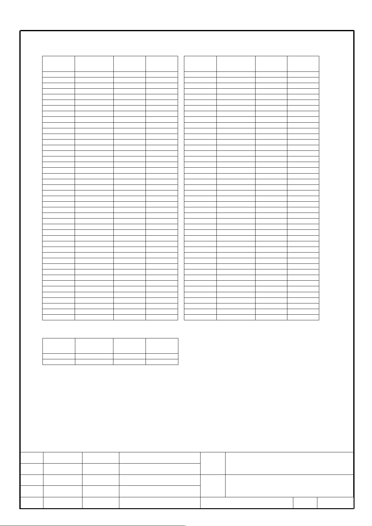
15. Parameters
DiS 120/600 (A06B-0493-B400)
These parameters are for HRV2 and applied for liquid cooling operation.
PRM NO SERVO PRM. 200V LC
400V LC
PRM NO SERVO PRM. 200V LC 400V LC
•
This motor can be used with liquid cooling only.
•
Please set parameters for a rotary encoder according to "Parameter Manual (B-65270EN/08)”.
•
The number of poles of this motor is 24.
01 15.06.04 Y.Sugimoto Newly Designed
Ed. Date Design Desctiption
M.Aochi
*LC stands for liquid cooling.
FANUC SYNCHRONOUS BUILT-IN
Title
SERVO MOTOR DiS series
DESCRIPTIONS
Draw B-65332EN/03-06
FANUC CORPORATION
PAGE
30/34
Page 31
2003
00001000
00001000
2067 TCMD FILTER
0 0
2004
10000011
10000011
2068-2073 0 0
2005
00000000
00000000
2074 AALPH
0 0
2006
00001000
00001000
2077-2083 0 0
2007
00000000
00000000
2086 RATED
3249 3249
2008
00000000
00000000
2087-2089 0 0
2009
00000000
00000000
2090 ROBSTL
400 600
2010
00000001
00000001
2091-2098 0 0
2011
00000000
00000000
2099 ONEPSL
400 400
2012
00000000
00000000
2100 INPA1
77 77
2013
00000101
00000101
2101 INPA2
0 0
2014
00100100
00100100
2102 DBLIM
0 0
2210
00000000
00000000
2103 ABVOF
0 0
2211
00000000
00000000
2104 ABTSH
0 0
2300
10000101
10000101
2105 TORQUE
16150
16150
2301
01000110
01000110
2106-2109 0 0
2560
01110001
01110001
2110 MG
STCM
2561 2561
2040 CUR GAIN I
2350 1400
2111 TQLIM IN DEC.
0 0
2041 CUR GAIN P
-7500 -
3500
2112 AMRDML
0 0
2042 CUR GAIN 3
-3136 -
3136
2113 HRV FILT
0 0
2043 VEL GAIN I
371 371
2127 NINTCT
0 0
2044 VEL GAIN P
-3324 -
3324
2128 MFWKCE
0 0
2045 VE
L GAIIN 3
0 0 2129 MFWKBL
0 0
2046 VEL GAIN4
-8235 -
8235
2130-2132 SMOOTH CMP
0 0
2047 OBSERVER
2537 2537
2133 PHDLY1
0 0
2048 BLACC CMP
0 0 2134 PHDLY2
0 0
2049 DPFMX
0 0 2159 DGCSMM
2580 3097
2050 OBSERVER
956 956
2160 TRQCUP
2660 2660
2051 OBSERVER
510 510
2161 OVC STP
122 122
2052 OVER SPEED
1440 1440
2162 OVC2 K1
32659
32659
2053 DB-CMP PPMAX
21 21
2163 OVC2 K2
1362 1362
2054 DB-CMP PDDP
1894 1894
2164 OVC2 LIMIT
588 588
2055 DB-CMP PHYST
319 319
2165 MAX CURRENT
365 365
2056 EMFCMP
0 0 2302 TQLIM AT STOP
14 14
2057 D-PHASE CUR
-1356 -
1356
2304 ACCBSLM
0 0
2058 D-PHASE CUR
-3004 -
3004
2305 ACDCEBD
0 0
2059 PPBAS
0 0 2310 DCIDBS
0 0
2060 TCMD LIMIT
7282 7282
2316 LIMLIM
4349 4349
2061 EMFLMT
0 0 2574 VELOVC
1440 1440
2062 OVC K1
32423
32423
2576 -23285
-23285
2063 OVC K2
4309 4309
2580
3366 3366
2064 TGALMLV
4 4 2590
10000
5400
2065 OVC LIMIT
10998
10998
2591 -14000
-7000
2066 ACC FB GAIN
0 0 2595 0 0
2271
0000
0001
0000
0001
2334
150 150
DiS 500/1200 (A06B-0495-B421)
These parameters are for HRV3 and applied for liquid cooling operation.
PRM NO SERVO PRM. 200V LC
400V LC
PRM NO SERVO PRM. 200V LC 400V LC
Set the following parameters in addition to the above.
PRM NO SERVO PRM. 200V LC
400V LC
•
This motor can be used with liquid cooling only.
•
This motor can be driven by HRV3 control only.
•
Please set parameters for a rotary encoder according to "Parameter Manual (B-65270EN/08)”.
•
The number of poles of this motor is 48.
01 15.06.04 Y.Sugimoto Newly Designed
Ed. Date Design Desctiption
M.Aochi
*LC stands for liquid cooling.
FANUC SYNCHRONOUS BUILT-IN
Title
SERVO MOTOR DiS series
DESCRIPTIONS
Draw B-65332EN/03-06
FANUC CORPORATION
PAGE
31/34
Page 32

2003
00001000
00001000
2067 TCMD FILTER
0 0
2004
10000011
10000011
2068-2073 0 0
2005
00000000
00000000
2074 AALPH
0 0
2006
00001000
00001000
2077-2083 0 0
2007
00000000
00000000
2086 RATED
3089 3089
2008
00000000
00000000
2087-2089 0 0
2009
00000000
00000000
2090 ROBSTL
280 550
2010
00000001
00000001
2091-2098 0 0
2011
00000000
00000000
2099 ONEPSL
400 400
2012
00000000
00000000
2100 INPA1
190 143
2013
00001001
00001001
2101 INPA2
0 0
2014
00101
000 00101000
2102 DBLIM
0 0
2210
00000000
00000000
2103 ABVOF
0 0
2211
00000000
00000000
2104 ABTSH
0 0
2300
10000101
10000101
2105 TORQUE
31811
31811
2301
01000110
01000110
2106-2109 0 0
2560
01110001
01110001
2110 MGSTCM
2561 2561
2040 CUR GAIN I
3000 2000
2111 TQLIM IN DEC.
0 0
2041 CUR GAIN P
-20000
-7000
2112 AMRDML
0 0
2042 CUR GAIN 3
-3169 -
3169
2113 HRV FILT
0 0
2043 VEL GAIN I
429 429
2127 NINTCT
0 0
2044 VEL GAIN P
-3842 -
3842
2128 MFWKCE
0 0
2045 VEL GAIIN 3
0 0 2129 MFWKBL
0 0
2046 VEL GAIN4
-8235 -
8235
2130-2132 SMOOTH CMP
0 0
2047 OBSERVER
2195 2195
2133 PHDLY1
0 0
2048 BLACC CMP
0 0 2134 PHDLY2
0 0
2049 DPFMX
0 0 2159 DGCSMM
7188 4638
2050 OBSERVER
956 956
2160 TRQCUP
5220 5220
2051 OBSE
RVER
510 510
2161 OVC STP
115 115
2052 OVER SPEED
600 1200
2162 OVC2 K1
32686
32686
2053 DB-CMP PPMAX
21 21
2163 OVC2 K2
1025 1025
2054 DB-CMP PDDP
1894 1894
2164 OVC2 LIMIT
284 284
2055 DB-CMP PHYST
319 319
2165 MAX CURRENT
365 365
2056 EMF
CMP 0 0
2302 TQLIM AT STOP
12 12
2057 D-PHASE CUR
-1330 -
1330
2304 ACCBSLM
0 0
2058 D-PHASE CUR
-1900 -
1900
2305 ACDCEBD
0 0
2059 PPBAS
0 0 2310 DCIDBS
0 0
2060 TCMD LIMIT
6068 6068
2316 LIMLIM
4551 4551
2061 EMFLMT
0 0 2574 VELOVC
1200 1200
2062
OVC K1
32294
32294
2576 -20985
-20985
2063 OVC K2
5920 5920
2580
1897 1897
2064 TGALMLV
4 4 2590
26000
14000
2065 OVC LIMIT
9941 9941
2591 -32000
-18000
2066 ACC FB GAIN
0 0 2595 0 0
2271
0000
0001
0000
0001
2334
150 150
DiS 1000/1000-385 (A06B-0499-B420)
These parameters are for HRV3 and applied for liquid cooling operation.
PRM NO SERVO PRM. 200V LC
400V LC
PRM NO SERVO PRM. 200V LC 400V LC
Set the following parameters in addition to the above.
PRM NO SERVO PRM. 200V LC
400V LC
•
This motor can be used with liquid cooling only.
•
This motor can be driven by HRV3 control only.
•
Please set parameters for a rotary encoder according to "Parameter Manual (B-65270EN/08)”.
•
The number of poles of this motor is 56.
01 15.06.04 Y.Sugimoto Newly Designed
Ed. Date Design Desctiption
M.Aochi
*LC stands for liquid cooling.
FANUC SYNCHRONOUS BUILT-IN
Title
SERVO MOTOR DiS series
DESCRIPTIONS
Draw B-65332EN/03-06
FANUC CORPORATION
PAGE
32/34
Page 33

2003 00001000
00001000
2067 TCMD FILTER
0 0
2004
10000011
10000011
2068-2073 0 0
2005
00000000
00000000
2074 AALPH
0 0
2006
00001000
00001000
2077-2083 0 0
2007
00000000
00000000
2086 RATED
3115 3115
2008
00000000
00000000
2087-2089 0 0
2009
00000000
00000000
2090 ROBSTL
300 570
2010
00000001
00000001
2091-2098 0 0
2011
00000000
00000000
2099 ONEPSL
400 400
2012
00000000
00000000
2100 INPA1
175 154
2013
00001001
00001001
2101 INPA2
0 0
2014
00101000
00101000
2102 DBLIM
0 0
2210
00000000
00000000
2103 ABVOF
0 0
2211
00000000
00000010
2104 ABTSH
0 0
2300
10000101
10000101
2105 TORQUE
30412
30412
2301
01000110
01000110
2106-2109 0 0
2560
01010001
01010001
2110 MGSTCM
2561 2561
2040 CUR GAIN I
1350 630
2111 TQLIM IN DEC.
0 0
2041 CUR GAIN P
-11300
-4600
2112 AMRDML
0 0
2042 CUR GAIN 3
-3172 -
3172
2113 HRV FILT
0 0
2043 VEL GAIN I
614 614
2127 NINTCT
0 0
2044 VEL GAIN P
-5504 -
5504
2128 MFWKCE
0 0
2045 VEL GAIIN 3
0 0 2129 MFWKBL
0 0
2046 VEL GAIN4
-8235 -
8235
2130-2132 SMOOTH CMP
0 0
2047 OBSERVER
1532 1532
2133 PHDLY1
0
25635
2048 BLACC CMP
0 0 2134 PHDLY2
0
7687
2049 DPFMX
0 0 2159 DGCSMM
4110 4628
2050 OBSERVER
956 956
2160 TRQCUP
5220 10340
2051 OBSERVER
510
510
2161 OVC STP
115 115
2052 OVER SPEED
600 1200
2162 OVC2 K1
32674
32674
2053 DB-CMP PPMAX
21 21
2163 OVC2 K2
1175 1175
2054 DB-CMP PDDP
1894 1894
2164 OVC2 LIMIT
343 343
2055 DB-CMP PHYST
319 319
2165 MAX CURRENT
365 365
2056 EMFCMP
0 0 2302 TQLIM AT STOP
11 11
2057 D-PHASE CUR
-2660 -
2660
2304 ACCBSLM
0 0
2058 D-PHASE CUR
-1950 -
1950
2305 ACDCEBD
0 0
2059 PPBAS
0 0 2310 DCIDBS
0 0
2060 TCMD LIMIT
6068 6068
2316 LIMLIM
4248 4248
2061 EMFLMT
0 0 2574 VELOVC
1175 1175
2062 OVC K1
32464
32464
2576 -6649 -
6649
2063 OVC K2
3800 3800
2580
1996 1996
2064 TGALMLV
4 4 2590
2120 1000
2065 OVC LIMIT
9867 9867
2591 -14000
-6800
2066 ACC FB GAIN
0 0 2595
1120 3860
2271
0000
0001
0000
0001
2334
150 150
DiS 1000/1000 (A06B-0496-B320)
These parameters are for HRV3 and applied for liquid cooling operation.
PRM NO SERVO PRM. 200V LC
400V LC
PRM NO SERVO PRM. 200V LC 400V LC
Set the following parameters in addition to the above.
PRM NO SERVO PRM. 200V LC
•
This motor can be used with liquid cooling only.
•
This motor can be driven by HRV3 control only.
•
Please set parameters for a rotary encoder according to "Parameter Manual (B-65270EN/08)”.
•
The number of poles of this motor is 64.
01 15.06.04 Y.Sugimoto Newly Designed
400V LC
Ed. Date Design Desctiption
M.Aochi
*LC stands for liquid cooling.
FANUC SYNCHRONOUS BUILT-IN
Title
SERVO MOTOR DiS series
DESCRIPTIONS
Draw B-65332EN/03-06
FANUC CORPORATION
PAGE
33/34
Page 34

2003
00001000
2067 TCMD F
ILTER
0
2004
10000011
2068-2073 0
2005
00000000
2074 AALPH
0
2006
00001000
2077-2083 0
2007
00000000
2086 RATED
2591
2008
00000000
2087-2089 0
2009
00000000
2090 ROBSTL
630
2010
00000001
2091-2098 0
2011
00000000
2099 ON
EPSL
400
2012
00000000
2100 INPA1
358
2013
00001001
2101 INPA2
0
2014
00101000
2102 DBLIM
0
2210
00000000
2103 ABVOF
0
2211
00000010
2104 ABTSH
0
2300
10000101
2105 TORQUE
16884
2301
11000110
2106-2109 0
2560 01
010001
2110 M
GSTCM
2049
2040 CUR GAIN I
1200
2111 TQLIM IN DEC.
0
2041 CUR GAIN P
-10000
2112 AMRDML
0
2042 CUR GAIN 3
-3149
2113 HRV FILT
0
2043 VEL GAIN I
1435
2127 NINTCT
0
2044 VEL GAIN P
-12851
2128 MFWKCE
0
2045 VEL GAIIN 3
0 2129 MFWKBL
0
2046 VEL G
AIN4 -
8235
2130-2132 SMOOTH CMP
0
2047 OBSERVER
656
2133 PHDLY1
12900
2048 BLACC CMP
0 2134 PHDLY2
6410
2049 DPFMX
0 2159 DGCSMM
9522
2050 OBSERVER
956
2160 TRQCUP
7760
2051 OBSERVER
510
2161 OVC STP
119
2052 OVER SPEED
600
2162
OVC2 K1
32674
2053 DB-CMP PPMAX
21
2163 OVC2 K2
1175
2054 DB-CMP PDDP
1894
2164 OVC2 LIMIT
224
2055 DB-CMP PHYST
319
2165 MAX CURRENT
545
2056 EMFCMP
0 2302 TQLIM AT STOP
6
2057 D-PHASE CUR
-939
2304 ACCBSLM
0
2058 D-PHASE CUR
-1800
2305 ACDC
EBD 0
2059 PPBAS
0 2310 DCIDBS
0
2060 TCMD LIMIT
6675
2316 LIMLIM
4046
2061 EMFLMT
0 2574 VELOVC
600
2062 OVC K1
32561
2576 -7159
2063 OVC K2
2583
2580
1734
2064 TGALMLV
4 2590
8000
2065 OVC LIMIT
6993
2591 -24000
2066 ACC FB GAIN
0 2595 1351
2271
0000
0001
2334
150
DiS 5000/500 (A06B-0488-B430)
These parameters are for HRV3 and applied for liquid cooling operation.
PRM NO SERVO PRM. 400V LC
PRM NO SERVO PRM. 400V LC
Set the following parameters in addition to the above.
PRM NO SERVO PRM. 400V LC
•
This motor can be used with liquid cooling only.
•
This motor can be driven by HRV3 control only.
•
This motor can be driven by only 400 V power voltage.
•
Please set parameters for a rotary encoder according to "Parameter Manual (B-65270EN/08)”.
•
The number of poles of this motor is 128.
01 15.06.04 Y.Sugimoto Newly Designed
Ed. Date Design Desctiption
M.Aochi
*LC stands for liquid cooling.
FANUC SYNCHRONOUS BUILT-IN
Title
SERVO MOTOR DiS series
DESCRIPTIONS
Draw B-65332EN/03-06
FANUC CORPORATION
PAGE
34/34
 Loading...