

Page 1
FANUC CORPORATION
Ed 1 Date
Design
Description
B-65382EN/05-06
Akasako
01
Newly designed
/87
Drawing
Akasako
02
Add M3 model, Correct
S1, S2, M2, M3 Model
Name
FANUC LINEAR MOTOR LiS series DESCRIPTIONS
/Version
Delete,
Function
Parts
Notice
Correction
Another
FANUC LINEAR MOTOR LiS-B series
1. Type of applied technical documents
Spec. No.
2. Summary of Change
Group Name
LINEAR MOTOR LiS-B series
Added M3 model
Basic
Function
Corrected continuous characteristic (No cooling) of
M2 model
Optional
Unit
B-65382EN/05
New, Add,
Applicable
Correct,
Data
Add Immediately
Correct Immediately
Maintenance
M3 model is added to LINEAR MOTOR LiS-B series.
FANUC LINEAR MOTOR LiS-B series
S1, S2, M2, M3 Model
No.
Page
Page 2
FANUC CORPORATION
Ed 2 Date
Design
Description
B-65382EN/05-06
Akasako
01
Newly designed
/87
Drawing
Akasako
02
Add M3 model, Correct
(D1 model)
(M2 model)
Magnet plate 180mm
A06B-0440-B413#0000
A06B-0440-B022#A180
Magnet plate 240mm
A06B-0440-B414#0000
A06B-0440-B022#A240
(Environmental resistance type)
(Environmental resistance type)
Servo Software
Series
Editions
90G0
25.0 and subsequent editions
90J0, K0
04.0 and subsequent editions
90J3
05.0 and subsequent editions
90JP
02.0 and subsequent editions
Series 0i-F
90M0, M8
02.0 and subsequent editions
3. OUTLINE
S1, S2, M2, M3 model are new models as LINEAR MOTOR LiS-B series.
This description shows the specification of FANUC LINEAR MOTOR LiS-B series.
M2 model is the renamed model of conventional D1 model (A06B-046-B△20) , external dimensions, force
characteristic etc. is fully compatible to D1 model. D1 model and M2 model has the following differences.
・ Coil Slider : Exactly the same as D1 model (same order number)
・ Magnet Plate : Appearance change only from D1 model (the shape of the magnet)
(New Order number)
Order number
Magnet plate 180mm
Magnet plate 240mm
・ Magnet Plate Protection Sheet : Exactly the same as D1 model (same order number)
LINEAR MOTOR LiS-B series has following characteristics.
• S1 model : downsizing narrow width, compared with conventional model (A1).
• Adding S2 model as width expansion model of S1.
• M2 model : downsizing narrow width, compared with conventional model (B2).
• Adding M3 model as width expansion model of M2.
02
• 200V and 400V drive available.
• Upgrade of Thermal Protection, device of overheat protection is changed to PTC thermistor from thermostat.
• Built-in NTC thermistor on all models for the display of motor internal temperature.
• Cabtyre cable is adopted for S1, S2 model power and signal line.
• Power and signal wiring of M2, M3 model are only connector type.
02
FANUC LINEAR MOTOR LiS series DESCRIPTIONS (B-65382EN/05) describes important information such as safety
precautions for protecting the user and preventing damage to the machine, considerations for designing the machine, and
start-up procedure. Be sure to read it in conjunction with this manual.
A06B-0440-B413#1002 A06B-0440-B022#E180
A06B-0440-B414#1002 A06B-0440-B022#E240
Order number
→
→
→
→
4. System Requirements
[CNC, Servo Software series and edi t ions]
The following table lists CNC and servo software series and edition for driving the motors described in this report.
Series 30i/31i/32i/35i-B
Power Motion i-A
CNC
FANUC LINEAR MOTOR LiS-B series
S1, S2, M2, M3 Model
No.
Page
Page 3
FANUC CORPORATION
Ed 3 Date
Design
Description
B-65382EN/05-06
Akasako
01
Newly designed
/87
Drawing
Akasako
02
Add M3 model, Correct
Model
Name
Order number
LiS 300S1/4-B
A06B-0424-B200#1002
LiS 600S1/4-B
A06B-0425-B200#1002
LiS 900S1/4-B
A06B-0426-B200#1002
LiS 600S2/3-B
A06B-0427-B200#1002
LiS 1200S2/3-B
A06B-0428-B200#1002
LiS 1800S2/3-B
A06B-0429-B200#1002
LiS 3000M2/2HV-B
A06B-0462-B020#1002
LiS 3000M2/2-B
A06B-0462-B120#1002
LiS 4500M2/2HV-B
A06B-0463-B020#1002
LiS 4500M2/2-B
A06B-0463-B120#1002
LiS 6000M2/2HV-B
A06B-0464-B020#1002
LiS 6000M2/2-B
A06B-0464-B120#1002
LiS 7500M2/2HV-B
A06B-0465-B020#1002
LiS 7500M2/2-B
A06B-0465-B120#1002
LiS 9000M2/2HV-B
A06B-0466-B020#1002
LiS 9000M2/2-B
A06B-0466-B120#1002
LiS 11000M2/2HV-B
A06B-0467-B020#1002
LiS 11000M2/2-B
A06B-0467-B120#1002
LiS 4500M3/2HV-B
A06B-0468-B020#1002
LiS 4500M3/2-B
A06B-0468-B120#1002
LiS 7000M3/2HV-B
A06B-0469-B020#1002
LiS 7000M3/2-B
A06B-0469-B120#1002
LiS 7000M3/4-B
A06B-0469-B220#1002
LiS 9000M3/2HV-B
A06B-0470-B020#1002
LiS 9000M3/2-B
A06B-0470-B120#1002
LiS 11000M3/2HV-B
A06B-0471-B020#1002
LiS 11000M3/2-B
A06B-0471-B120#1002
LiS 14000M3/2HV-B
A06B-0472-B020#1002
LiS 14000M3/2-B
A06B-0472-B120#1002
LiS 16000M3/2HV-B
A06B-0473-B020#1002
LiS 16000M3/2-B
A06B-0473-B120#1002
5. Type and Order number
5-1 Coil Slider
S1
S2
M2
M3
02
FANUC LINEAR MOTOR LiS-B series
S1, S2, M2, M3 Model
No.
Page
Page 4
FANUC CORPORATION
Ed 4 Date
Design
Description
B-65382EN/05-06
Akasako
01
Newly designed
/87
Drawing
Akasako
02
Add M3 model, Correct
Model
Name
Order number
Magnet plate for S1 90mm
A06B-0440-B011#A090
Magnet plate for S1 120mm
A06B-0440-B011#A120
Magnet plate for S2 90mm
A06B-0440-B012#A090
Magnet plate for S2 120mm
A06B-0440-B012#A120
Magnet plate for M2 180mm
A06B-0440-B022#A180
Magnet plate for M2 240mm
A06B-0440-B022#A240
(Environmental resistance type)
(Environmental resistance type)
Magnet plate for M3 180mm
A06B-0440-B023#A180
Magnet plate for M3 240mm
A06B-0440-B023#A240
(Environmental resistance type)
(Environmental resistance type)
5-2 Magnet Plate
S1
S2
M2
02
Magnet plate for M2 180mm
Magnet plate for M2 240mm
M3
Magnet plate for M3 180mm
Magnet plate for M3 240mm
A06B-0440-B022#E180
A06B-0440-B022#E240
A06B-0440-B023#E180
A06B-0440-B023#E240
FANUC LINEAR MOTOR LiS-B series
S1, S2, M2, M3 Model
No.
Page
Page 5
FANUC CORPORATION
Ed 5 Date
Design
Description
B-65382EN/05-06
Akasako
01
Newly designed
/87
Drawing
Akasako
02
Add M3 model, Correct
Model
Name
Order number
Protection Sheet for S1 (Length 1000mm)
A06B-0440-K770#100
Protection Sheet for S1 (Length 1500mm)
A06B-0440-K770#150
Protection Sheet for S1 (Length 2000mm)
A06B-0440-K770#200
Protection Sheet for S1 (Length 2500mm)
A06B-0440-K770#250
Protection Sheet for S1 (Length 3000mm)
A06B-0440-K770#300
Protection Sheet for S2 (Length 1000mm)
A06B-0440-K780#100
Protection Sheet for S2 (Length 1500mm)
A06B-0440-K780#150
Protection Sheet for S2 (Length 2000mm)
A06B-0440-K780#200
Protection Sheet for S2 (Length 2500mm)
A06B-0440-K780#250
Protection Sheet for S2 (Length 3000mm)
A06B-0440-K780#300
Protection Sheet for M2 (Length 2000mm)
A06B-0440-K760#200
Protection Sheet for M2 (Length 2500mm)
A06B-0440-K760#250
Protection Sheet for M2 (Length 3000mm)
A06B-0440-K760#300
Protection Sheet for M3 (Length 2000mm)
A06B-0440-K790#200
Protection Sheet for M3 (Length 2500mm)
A06B-0440-K790#250
Protection Sheet for M3 (Length 3000mm)
A06B-0440-K790#300
Model
Name
Order number
Cooling plate for LiS 300S1/4-B
A06B-0443-K001#01A1
Cooling plate for LiS 600S1/4-B
A06B-0443-K001#02A1
Cooling plate for LiS 900S1/4-B
A06B-0443-K001#03A1
Cooling plate for LiS 600S2/3-B
A06B-0443-K001#01S2
Cooling plate for LiS 1200S2/3-B
A06B-0443-K001#02S2
Cooling plate for LiS 1800S2/3-B
A06B-0443-K001#03S2
5-3 Magnet Plate Protection Sheet
S1
S2
M2
M3
02
The character in the specification number indic ates the number of sheets.
“0”: One sheet “A”: Ten sheets * Either "0" or "A" can be selected.
5-4 Cooling Plate
S1
(Note)
S2
Note : Cooling plates for the S1 model are same as the cooling plates for the A1 model .
FANUC LINEAR MOTOR LiS-B series
S1, S2, M2, M3 Model
No.
Page
Page 6
FANUC CORPORATION
Ed 6 Date
Design
Description
B-65382EN/05-06
Akasako
01
Newly designed
/87
Drawing
Akasako
02
Add M3 model, Correct
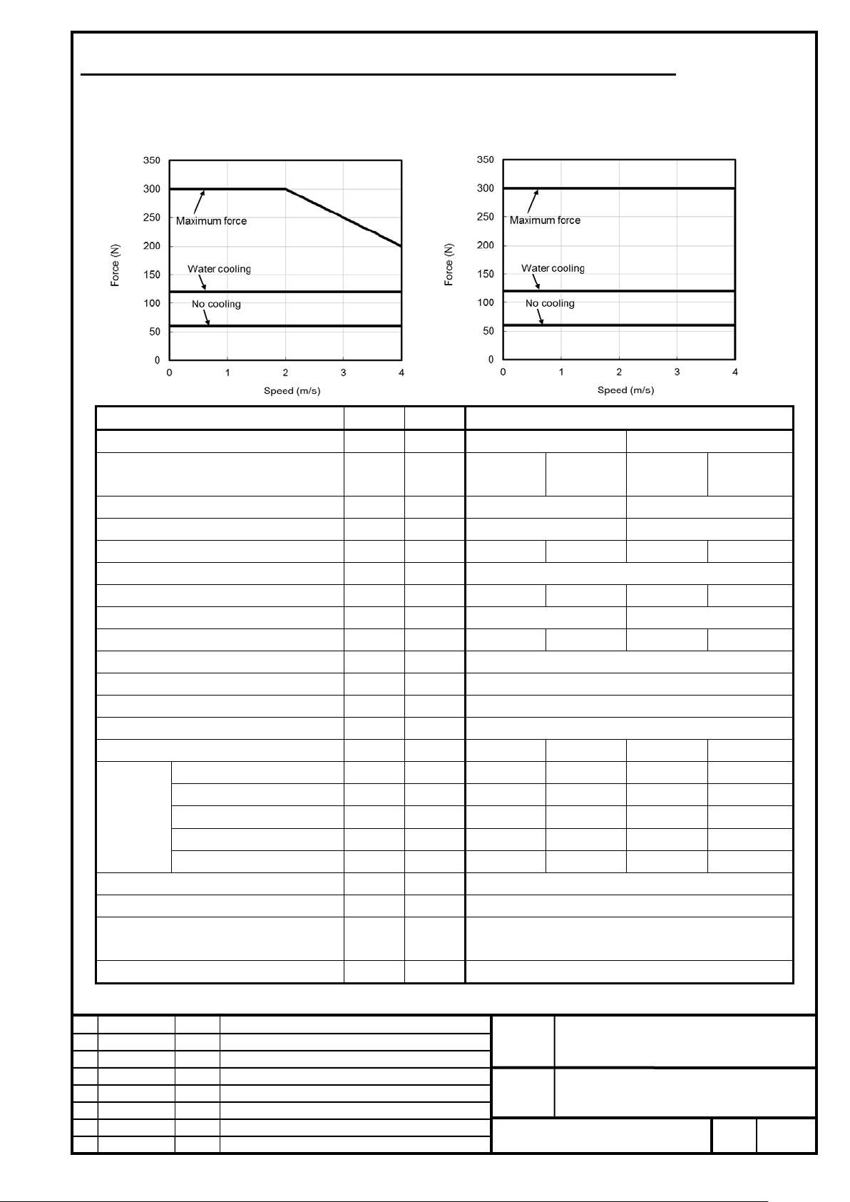
Item
Symbol
Unit
Value
Input power voltage
-
V
200
400
cooling
cooling
Maximum speed*3
-
m/s
4
4
Upper speed for the maximum force
-
m/s
2 4 Continuous force *4
Fc N 60
120
60
120
Maximum force
FMAX
N
300
Continuous output
Pc
kW
0.24
0.48
0.24
0.48
Maximum output
PMAX
kW
0.80
1.2
Continuous current *4
Ic
Arms
1.4
3.0
1.4
3.0
Maximum current
IMAX
Arms
11.3
Maximum amplifier current
-
Ap
20
Force constant
Kf
N/Arms
45.0
Resistance between terminals
Ra
5.83
Thermal time constant
tt min
30
0.5
30
0.5
Coolant *6
-
-
Water
Water
Flow rate
-
L/min
4.0
4.0
Recommended pressure
-
MPa
0.1
0.1
Maximum pressure
-
MPa
0.3
0.3
Required cooling capacity
-
W
100
100
Magnetic attraction *7
Fa
N
900
Mass of coil slider *8
W
kg
0.96
transportation and storage), non-condensing
Type of applicable magnet plate *10
-
-
S1
6. SPECIFICATION LIST AND FORCE-SPEED CHARACTERISTICS CHART
LiS 300S1/4-B (A06B-0424-B200#1002)
200V
400V
Cooling method *2 - - No cooling
Water
No cooling
Water
conditions
Cooling
*5
Ω
Use environment *9 - -
-
-
-
-
-
Ambient temperature: 0 to 40°C (including during
FANUC LINEAR MOTOR LiS-B series
No.
-
-
-
-
-
S1, S2, M2, M3 Model
Page
Page 7
FANUC CORPORATION
Ed 7 Date
Design
Description
B-65382EN/05-06
Akasako
01
Newly designed
/87
Drawing
Akasako
02
Add M3 model, Correct
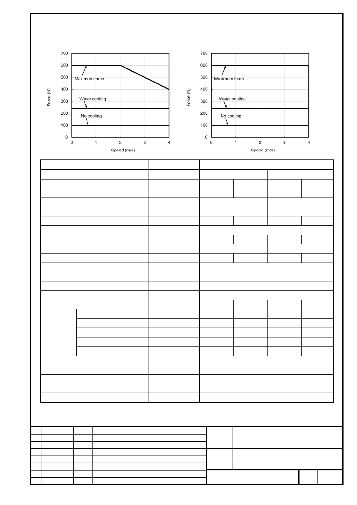
Item
Symbol
Unit
Value
Input power voltage
-
V
200
400
cooling
cooling
Maximum speed*3
-
m/s
4
4
Upper speed for the maximum force
-
m/s
2 4 Continuous force *4
Fc N 100
240
100
240
Maximum force
FMAX
N
600
Continuous output
Pc
kW
0.40
0.96
0.40
0.96
Maximum output
PMAX
kW
1.6
2.4
Continuous current *4
Ic
Arms
2.4
6.0
2.4
6.0
Maximum current
IMAX
Arms
22.6
Maximum amplifier current
-
Ap
40
Force constant
Kf
N/Arms
45.0
Resistance between terminals
Ra
2.94
Thermal time constant
tt min
30
0.5
30
0.5
Coolant *6
-
-
Water
Water
Flow rate
-
L/min
4.0
4.0
Recommended pressure
-
MPa
0.1
0.1
Maximum pressure
-
MPa
0.3
0.3
Required cooling capacity
-
W
200
200
Magnetic attraction *7
Fa
N
1800
Mass of coil slider *8
W
kg
1.62
transportation and storage), non-condensing
Type of applicable magnet plate *10
-
-
S1
LiS 600S1/4-B (A06B-0425-B200#1002)
200V
400V
Cooling
conditions
*5
Cooling method *2 - - No cooling
Ω
-
-
-
-
-
Water
No cooling
-
-
-
-
-
Water
Use environment *9 - -
Ambient temperature: 0 to 40°C (including during
FANUC LINEAR MOTOR LiS-B series
S1, S2, M2, M3 Model
No.
Page
Page 8
FANUC CORPORATION
Ed 8 Date
Design
Description
B-65382EN/05-06
Akasako
01
Newly designed
/87
Drawing
Akasako
02
Add M3 model, Correct
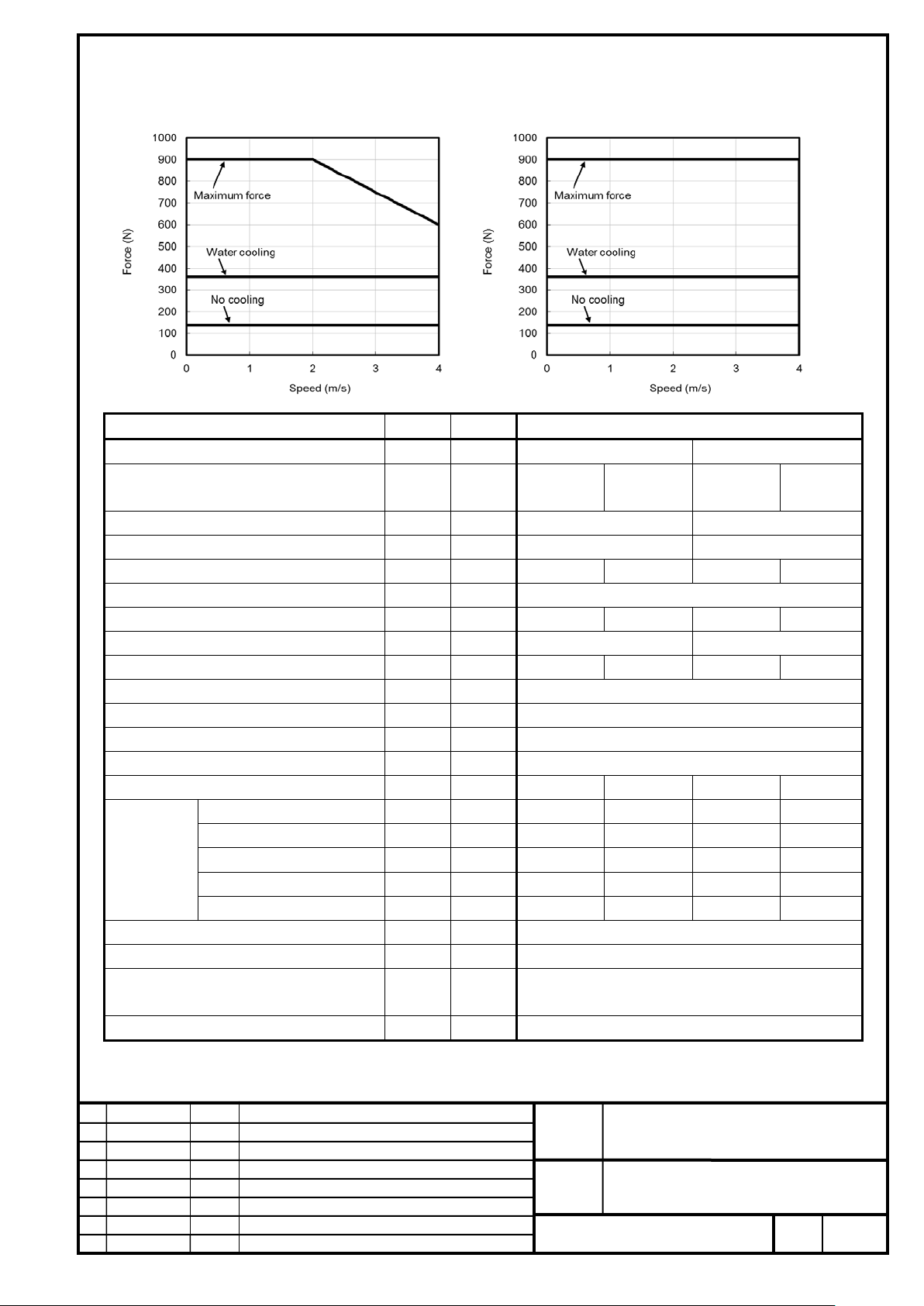
Item
Symbol
Unit
Value
-
cooling
cooling
Upper speed for the maximum force
-
m/s
2
4
Maximum force
F
N
900
Maximum output
P
kW
2.4
3.6
Continuous current *4
Ic
Arms
3.2
9.0
3.2
9.0
Maximum current
I
Arms
33.9
Maximum amplifier current
-
Ap
80
Force constant
Kf
N/Arms
45.0
Resistance between terminals
Ra Ω
1.97
Thermal time constant
tt min
30
0.5
30
0.5
Coolant *6
-
-
Water -
Water
Flow rate
-
L/min
4.0 -
4.0
Recommended pressure
-
MPa
0.1 -
0.1
Maximum pressure
-
MPa
0.3 -
0.3
Required cooling capacity
-
W
300 -
300
Magnetic attraction *7
Fa
N
2700
Mass of coil slider *8
W
kg
2.30
transportation and storage), non-condensing
Type of applicable magnet plate *10
-
-
S1
LiS 900S1/4-B (A06B-0426-B200#1002)
200V
400V
Cooling
conditions
*5
Input power voltage
Cooling method *2 - - No cooling
Maximum speed *3 - m/s 4 4
Continuous force *4 Fc N 140 360 140 360
MAX
Continuous output Pc kW 0.56 1.4 0.56 1.4
MAX
MAX
V 200 400
Water
-
-
-
-
-
No cooling
Water
Use environment *9 - -
Ambient temperature: 0 to 40°C (including during
FANUC LINEAR MOTOR LiS-B series
S1, S2, M2, M3 Model
No.
Page
Page 9
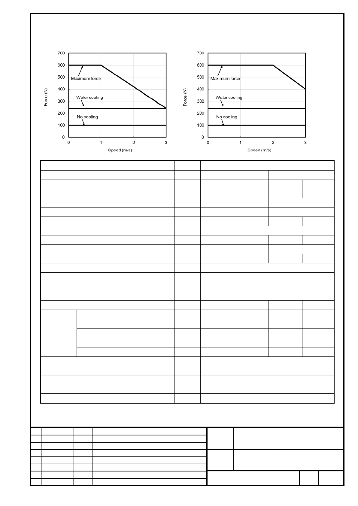
FANUC CORPORATION
Ed 9 Date
Design
Description
B-65382EN/05-06
Akasako
01
Newly designed
/87
Drawing
Akasako
02
Add M3 model, Correct
Item
Symbol
Unit
Value
Input power voltage
-
V
200
400
cooling
cooling
Maximum speed*3
-
m/s
3
3
Upper speed for the maximum force
-
m/s
1 2 Continuous force *4
Fc N 100
240
100
240
Maximum force
FMAX
N
600
Continuous output
Pc
kW
0.30
0.72
0.30
0.72
Maximum output
PMAX
kW
0.84
1.3
Continuous current *4
Ic
Arms
1.2
3.0
1.2
3.0
Maximum current
IMAX
Arms
11.3
Maximum amplifier current
-
Ap
20
Force constant
Kf
N/Arms
90.0
Resistance between terminals
Ra
Ω
9.54
Thermal time constant
tt min
30
0.5
30
0.5
Coolant *6
- -
Water
Water
Flow rate
L/min
4.0
4.0
Recommended pressure
MPa
0.1
0.1
Maximum pressure
MPa
0.3
0.3
Required cooling capacity
W
200
200
Magnetic attraction *7
Fa
N
1800
Mass of coil slider *8
W
kg
1.58
transportation and storage), non-condensing
Type of applicable magnet plate *10
-
-
S2
LiS 600S2/3-B (A06B-0427-B200#1002)
200V
Cooling method *2 - - No cooling
400V
Water
No cooling
Water
Cooling
conditions
*5
-
-
-
-
-
Use environment *9 - -
-
-
-
-
-
Ambient temperature: 0 to 40°C (including during
FANUC LINEAR MOTOR LiS-B series
S1, S2, M2, M3 Model
No.
-
-
-
-
Page
Page 10
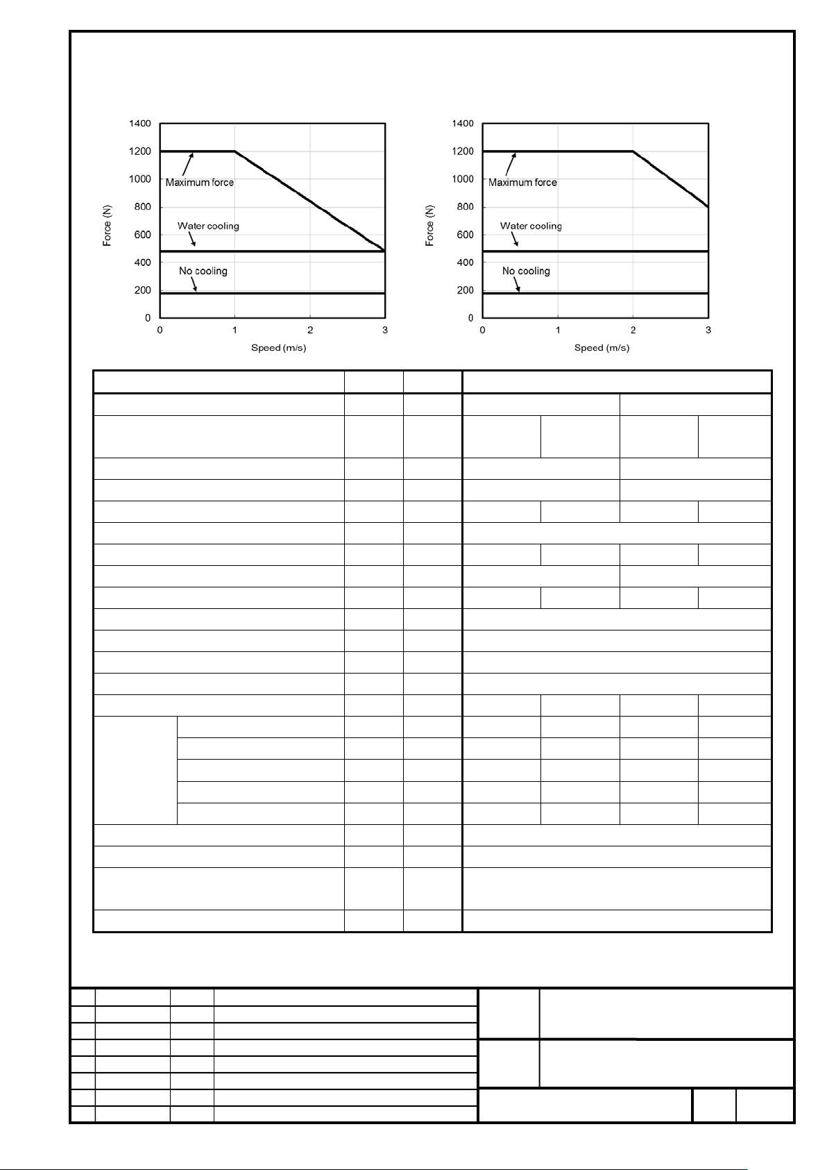
FANUC CORPORATION
Ed
Date
Design
Description
B-65382EN/05-06
Akasako
01
Newly designed
/87
Drawing
Akasako
02
Add M3 model, Correct
Item
Symbol
Unit
Value
Input power voltage
-
V
200
400
cooling
cooling
Maximum speed*3
-
m/s
3
3
Upper speed for the maximum force
-
m/s
1 2 Continuous force *4
Fc N 180
480
180
480
Maximum force
FMAX
N
1200
Continuous output
Pc
kW
0.54
1.4
0.54
1.4
Maximum output
PMAX
kW
1.7
2.5
Continuous current *4
Ic
Arms
2.1
6.0
2.1
6.0
Maximum current
IMAX
Arms
22.6
Maximum amplifier current
-
Ap
40
Force constant
Kf
N/Arms
90.0
Resistance between terminals
Ra
Ω
4.77
Thermal time constant
tt min
30
0.5
30
0.5
Coolant *6
-
-
Water
Water
Flow rate
-
L/min
4.0
4.0
Recommended pressure
-
MPa
0.1
0.1
Maximum pressure
-
MPa
0.3
0.3
Required cooling capacity
-
W
350
350
Magnetic attraction *7
Fa
N
3600
Mass of coil slider *8
W
kg
2.82
transportation and storage), non-condensing
Type of applicable magnet plate *10
-
-
S2
LiS 1200S2/3-B (A06B-0428-B200#1002)
200V
400V
Cooling
conditions
*5
Cooling method *2 - - No cooling
-
-
-
-
-
Water
No cooling
-
-
-
-
-
Water
Use environment *9 - -
Ambient temperature: 0 to 40°C (including during
FANUC LINEAR MOTOR LiS-B series
S1, S2, M2, M3 Model
No.
Page
10
Page 11

FANUC CORPORATION
Ed
Date
Design
Description
B-65382EN/05-06
Akasako
01
Newly designed
/87
Drawing
Akasako
02
Add M3 model, Correct
Item
Symbol
Unit
Value
Input power voltage
-
V
200
400
cooling
cooling
Maximum speed *3
-
m/s
3
3
Upper speed for the maximum force
-
m/s
1 2 Continuous force *4
Fc N 260
720
260
720
Maximum force
FMAX
N
1800
Continuous output
Pc
kW
0.78
2.2
0.78
2.2
Maximum output
PMAX
kW
2.5
3.8
Continuous current *4
Ic
Arms
3.0
9.0
3.0
9.0
Maximum current
IMAX
Arms
33.9
Maximum amplifier current
-
Ap
80
Force constant
Kf
N/Arms
90.0
Resistance between terminals
Ra
Ω
3.19
Thermal time constant
tt min
30
0.5
30
0.5
Coolant *6
- -
Water
Water
Flow rate
L/min
4.0
4.0
Recommended pressure
MPa
0.1
0.1
Maximum pressure
MPa
0.3
0.3
Required cooling capacity
W
500
500
Magnetic attraction *7
Fa
N
5400
Mass of coil slider *8
W
kg
4.0
transportation and storage), non-condensing
Type of applicable magnet plate *10
-
S2
LiS 1800S2/3-B (A06B-0429-B200#1002)
200V
400V
Cooling
conditions
*5
Cooling method *2 - - No cooling
-
-
-
-
-
-
-
-
-
Water
No cooling
-
-
-
-
-
Water
Use environment *9
- -
-
Ambient temperature: 0 to 40°C (including during
FANUC LINEAR MOTOR LiS-B series
S1, S2, M2, M3 Model
No.
Page
11
Page 12
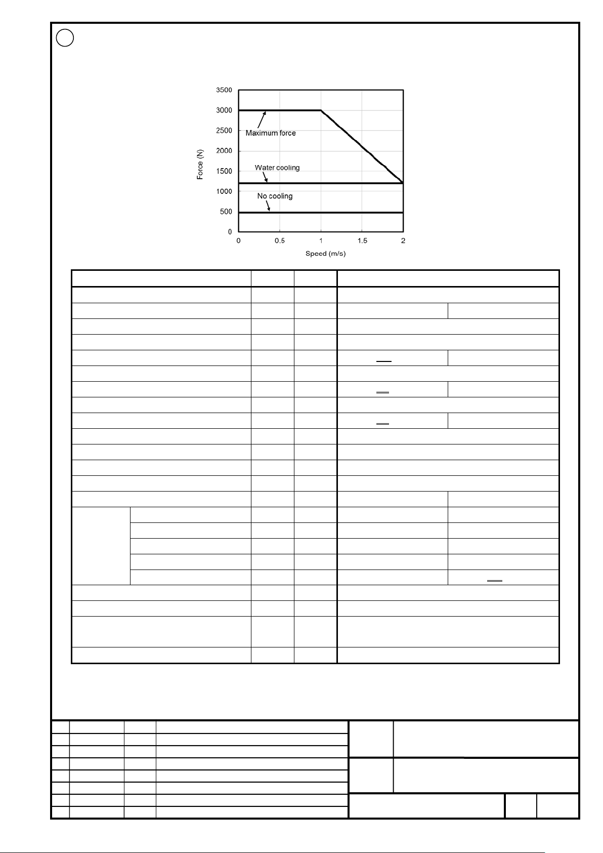
FANUC CORPORATION
Ed
Date
Design
Description
B-65382EN/05-06
Akasako
01
Newly designed
/87
Drawing
Akasako
02
Add M3 model, Correct
Item
Symbol
Unit
Value
Input power voltage
-
V
400
Cooling method *2
- - No cooling
Water cooling
Maximum speed *3
-
m/s 2 Upper speed for the maximum force
-
m/s 1 Continuous force *4
Fc N 600 480
1200
Maximum force
FMAX
N
3000
Continuous output
Pc
kW
1.2 0.96
2.4
Maximum output
PMAX
kW
3.2
Continuous current *4
Ic
Arms
2.3 1.84
4.6
Maximum current
IMAX
Arms
16.2
Maximum amplifier current
-
Ap
40
Force constant
Kf
N/Arms
261.45
Resistance between terminals
Ra
12.22
Thermal time constant
tt min
60
1
Coolant *6
-
-
Water
Flow rate
-
L/min
7.5
Recommended pressure
-
MPa
0.11
Maximum pressure
-
MPa
0.63
Required cooling capacity
-
W
600 500
Magnetic attraction *7
Fa
N
9000
Mass of coil slider *8
W
kg
8.5
transportation and storage), non-condensing
Type of applicable magnet plate *10
-
-
M2
02
LiS 3000M2/2HV-B (A06B-0462-B020#1002)
400V
Cooling
conditions
*5
Ω
Use environment *9 - -
-
-
-
-
-
Ambient temperature: 0 to 40°C (including during
FANUC LINEAR MOTOR LiS-B series
S1, S2, M2, M3 Model
No.
Page
12
Page 13

FANUC CORPORATION
Ed
Date
Design
Description
B-65382EN/05-06
Akasako
01
Newly designed
/87
Drawing
Akasako
02
Add M3 model, Correct
Item
Symbol
Unit
Value
Input power voltage
-
V
200
400
cooling
cooling
Maximum speed*3
-
m/s
2
4
Upper speed for the maximum force
-
m/s
1 2 Continuous force *4
Fc N 600 480
1200
600 480
1200
Maximum force
FMAX
N
3000
Continuous output
Pc
kW
1.2 0.96
2.4
2.4 1.92
4.8
Maximum output
PMAX
kW
3.2
6.4
Continuous current *4
Ic
Arms
5.0 4.0
10.0
5.0 4.0
10.0
Maximum current
IMAX
Arms
35.4
Maximum amplifier current
-
Ap
80
Force constant
Kf
N/Arms
119.9
Resistance between terminals
Ra
2.64
Thermal time constant
tt min
60 1 60
1
Coolant *6
- - -
Water
-
Water
Flow rate
-
L/min - 7.5 - 7.5
Recommended pressure
-
MPa - 0.11 - 0.11
Maximum pressure
-
MPa - 0.63 - 0.63
Required cooling capacity
- W -
600 500
-
600 500
Magnetic attraction *7
Fa
N
9000
Mass of coil slider *8
W
kg
8.5
transportation and storage), non-condensing
Type of applicable magnet plate *10
-
-
M2
02
LiS 3000M2/2-B (A06B-0462-B120#1002)
200V
400V
Cooling method *2 - - No cooling
Water
No cooling
Water
Cooling
conditions
*5
Ω
Use environment *9 - -
Ambient temperature: 0 to 40°C (including during
FANUC LINEAR MOTOR LiS-B series
S1, S2, M2, M3 Model
No.
Page
13
Page 14
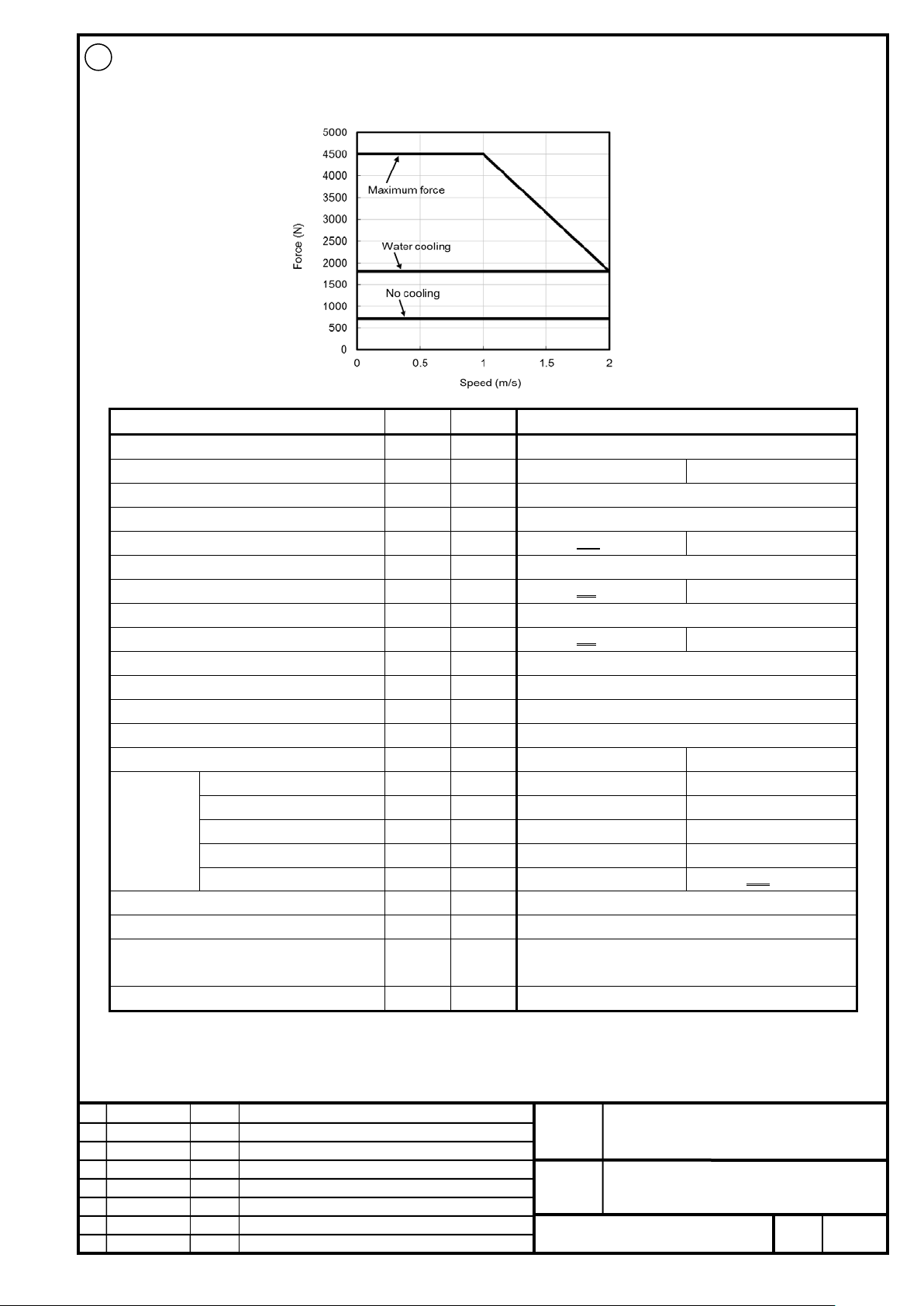
FANUC CORPORATION
Ed
Date
Design
Description
B-65382EN/05-06
Akasako
01
Newly designed
/87
Drawing
Akasako
02
Add M3 model, Correct
Item
Symbol
Unit
Value
Input power voltage
-
V
400
Cooling method *2
- - No cooling
Water cooling
Maximum speed *3
-
m/s 2 Upper speed for the maximum force
-
m/s 1 Continuous force *4
Fc N 900 720
1800
Maximum force
FMAX
N
4500
Continuous output
Pc
kW
1.8 1.44
3.6
Maximum output
PMAX
kW
4.8
Continuous current *4
Ic
Arms
3.4 2.72
6.9
Maximum current
IMAX
Arms
24.2
Maximum amplifier current
-
Ap
40
Force constant
Kf
N/Arms
261.45
Resistance between terminals
Ra
8.16
Thermal time constant
tt min
60
1
Coolant *6
-
-
Water
Flow rate
-
L/min
7.5
Recommended pressure
-
MPa
0.15
Maximum pressure
-
MPa
0.63
Required cooling capacity
-
W
900 750
Magnetic attraction *7
Fa
N
13500
Mass of coil slider *8
W
kg
12.2
transportation and storage), non-condensing
Type of applicable magnet plate *10
-
-
M2
02
LiS 4500M2/2HV-B (A06B-0463-B020#1002)
400V
Cooling
conditions
*5
Ω
Use environment *9 - -
-
-
-
-
-
Ambient temperature: 0 to 40°C (including during
FANUC LINEAR MOTOR LiS-B series
S1, S2, M2, M3 Model
No.
Page
14
Page 15
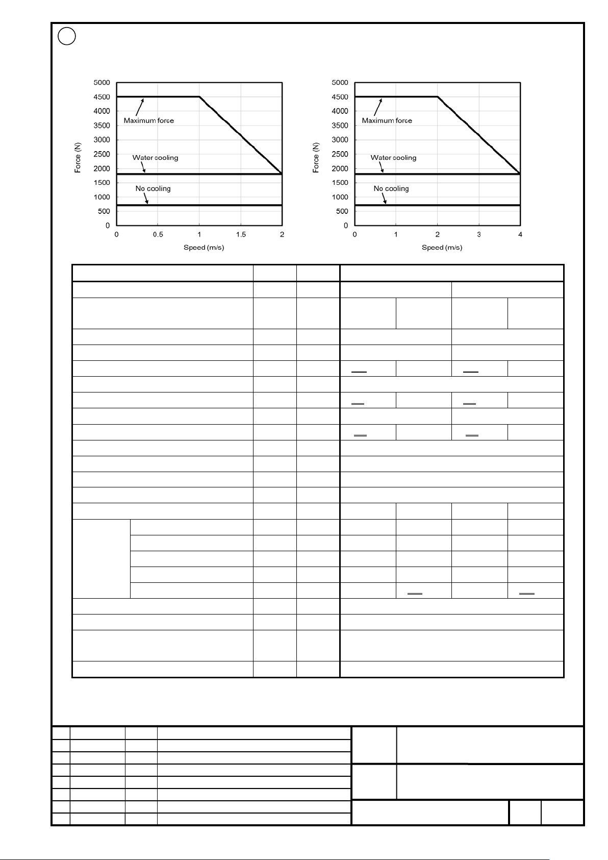
FANUC CORPORATION
Ed
Date
Design
Description
B-65382EN/05-06
Akasako
01
Newly designed
/87
Drawing
Akasako
02
Add M3 model, Correct
Item
Symbol
Unit
Value
Input power voltage
-
V
200
400
cooling
cooling
Maximum speed*3
-
m/s
2
4
Upper speed for the maximum force
-
m/s
1 2 Continuous force *4
Fc N 900 720
1800
900 720
1800
Maximum force
FMAX
N
4500
Continuous output
Pc
kW
1.8 1.44
3.6
3.6 2.88
7.2
Maximum output
PMAX
kW
4.8
9.6
Continuous current *4
Ic
Arms
7.5 6.0
15.0
7.5 6.0
15.0
Maximum current
IMAX
Arms
53
Maximum amplifier current
-
Ap
80
Force constant
Kf
N/Arms
119.9
Resistance between terminals
Ra
1.76
Thermal time constant
tt min
60 1 60
1
Coolant *6
- - -
Water
-
Water
Flow rate
-
L/min - 7.5 - 7.5
Recommended pressure
-
MPa - 0.15 - 0.15
Maximum pressure
-
MPa - 0.63 - 0.63
Required cooling capacity
- W -
900 750
-
900 750
Magnetic attraction *7
Fa
N
13500
Mass of coil slider *8
W
kg
12.2
transportation and storage), non-condensing
Type of applicable magnet plate *10
-
-
M2
02
LiS 4500M2/2-B (A06B-0463-B120#1002)
200V
400V
Cooling method *2 - - No cooling
Water
No cooling
Water
Cooling
conditions
*5
Ω
Use environment *9 - -
Ambient temperature: 0 to 40°C (including during
FANUC LINEAR MOTOR LiS-B series
S1, S2, M2, M3 Model
No.
Page
15
Page 16
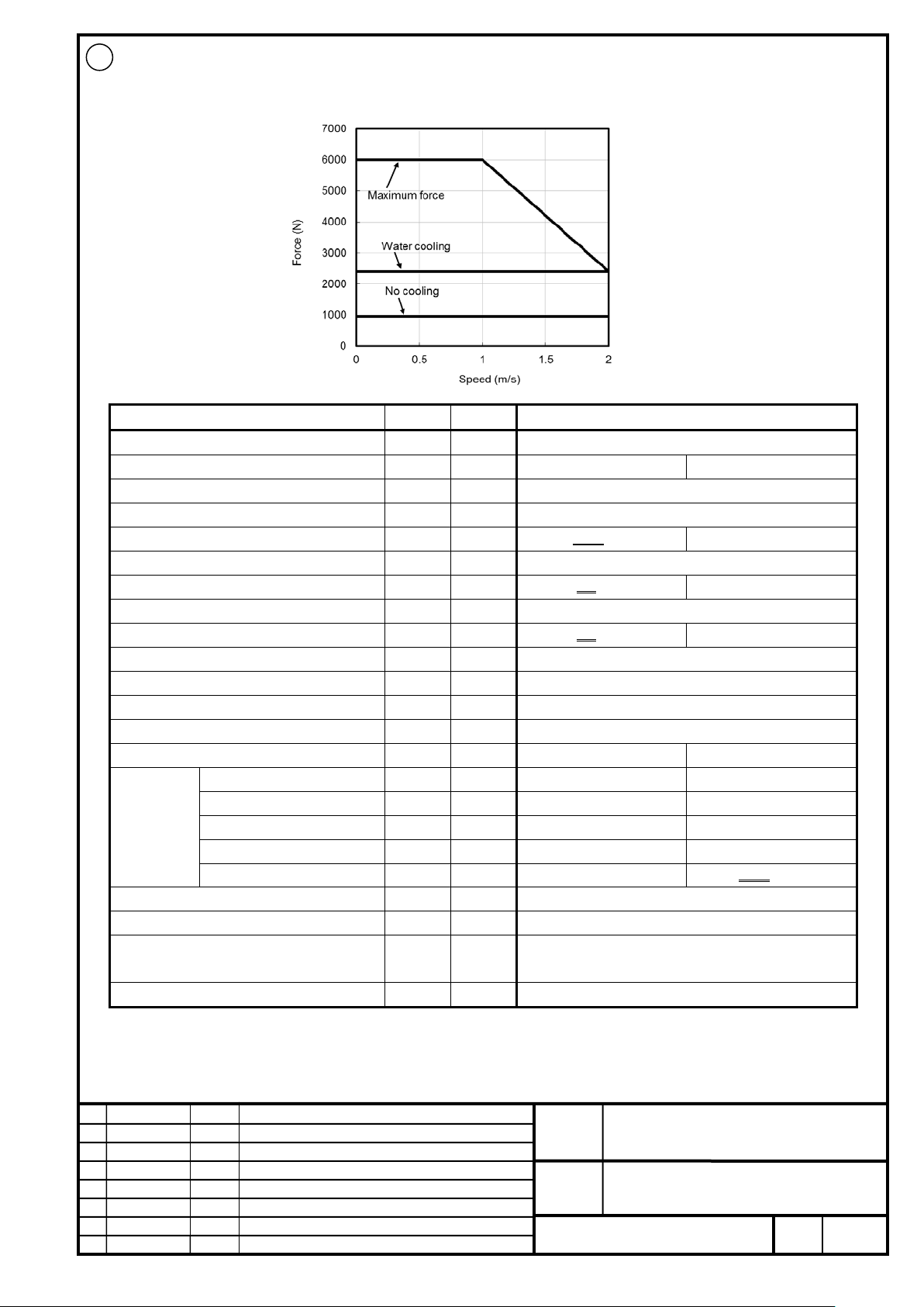
FANUC CORPORATION
Ed
Date
Design
Description
B-65382EN/05-06
Akasako
01
Newly designed
/87
Drawing
Akasako
02
Add M3 model, Correct
Item
Symbol
Unit
Value
Input power voltage
-
V
400
Cooling method *2
- - No cooling
Water cooling
Maximum speed *3
-
m/s 2 Upper speed for the maximum force
-
m/s 1 Continuous force *4
Fc N 1200 960
2400
Maximum force
FMAX
N
6000
Continuous output
Pc
kW
2.4 1.92
4.8
Maximum output
PMAX
kW
6.4
Continuous current *4
Ic
Arms
4.6 3.68
9.2
Maximum current
IMAX
Arms
32.3
Maximum amplifier current
-
Ap
80
Force constant
Kf
N/Arms
261.45
Resistance between terminals
Ra
6.12
Thermal time constant
tt min
60
1
Coolant *6
-
-
Water
Flow rate
-
L/min
7.5
Recommended pressure
-
MPa
0.17
Maximum pressure
-
MPa
0.63
Required cooling capacity
-
W
1200 1000
Magnetic attraction *7
Fa
N
18000
Mass of coil slider *8
W
kg
15.9
transportation and storage), non-condensing
Type of applicable magnet plate *10
-
-
M2
02
LiS 6000M2/2HV-B (A06B-0464-B020#1002)
400V
Cooling
conditions
*5
Ω
Use environment *9 - -
-
-
-
-
-
Ambient temperature: 0 to 40°C (including during
FANUC LINEAR MOTOR LiS-B series
S1, S2, M2, M3 Model
No.
Page
16
Page 17
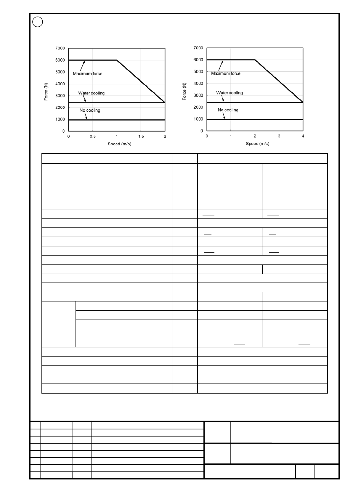
FANUC CORPORATION
Ed
Date
Design
Description
B-65382EN/05-06
Akasako
01
Newly designed
/87
Drawing
Akasako
02
Add M3 model, Correct
Item
Symbol
Unit
Value
Input power voltage
-
V
200
400
cooling
cooling
Maximum speed*3
-
m/s
2
4
Upper speed for the maximum force
-
m/s
1 2 Continuous force *4
Fc N 1200 960
2400
1200 960
2400
Maximum force
FMAX
N
6000
Continuous output
Pc
kW
2.4 1.92
4.8
4.8 3.84
9.6
Maximum output
PMAX
kW
6.4
12.8
Continuous current *4
Ic
Arms
10.0 8.0
20.0
10.0 8.0
20.0
Maximum current
IMAX
Arms
70.7
Maximum amplifier current
-
Ap
160
180
Force constant
Kf
N/Arms
119.9
Resistance between terminals
Ra
1.32
Thermal time constant
tt min
60 1 60
1
Coolant *6
- - -
Water
-
Water
Flow rate
-
L/min - 7.5 - 7.5
Recommended pressure
-
MPa - 0.17 - 0.17
Maximum pressure
-
MPa - 0.63 - 0.63
Required cooling capacity
- W -
1200 1000
-
1200 1000
Magnetic attraction *7
Fa
N
18000
Mass of coil slider *8
W
kg
15.9
transportation and storage), non-condensing
Type of applicable magnet plate *10
-
-
M2
02
LiS 6000M2/2-B (A06B-0464-B120#1002)
200V
400V
Cooling
conditions
*5
Cooling method *2 - - No cooling
Ω
Water
No cooling
Water
Use environment *9 - -
Ambient temperature: 0 to 40°C (including during
FANUC LINEAR MOTOR LiS-B series
S1, S2, M2, M3 Model
No.
Page
17
Page 18
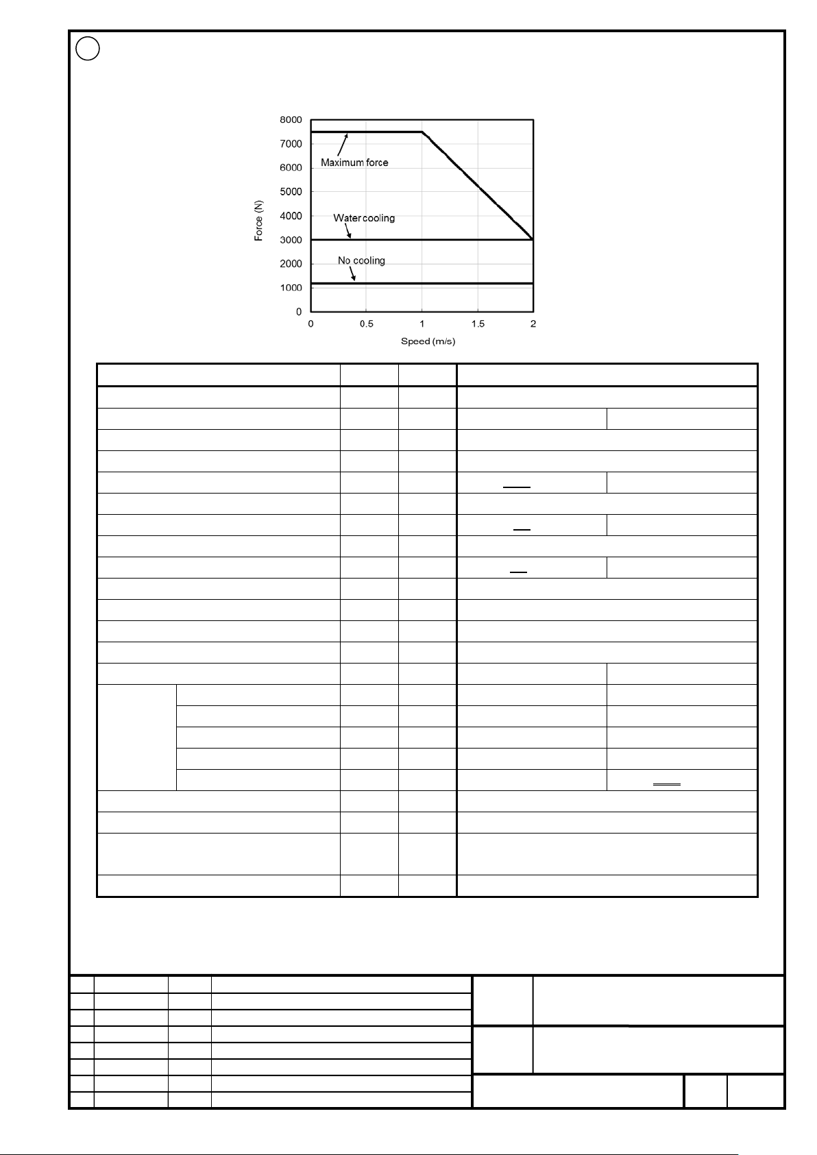
FANUC CORPORATION
Ed
Date
Design
Description
B-65382EN/05-06
Akasako
01
Newly designed
/87
Drawing
Akasako
02
Add M3 model, Correct
Item
Symbol
Unit
Value
Input power voltage
-
V
400
Cooling method *2
- - No cooling
Water cooling
Maximum speed *3
-
m/s 2 Upper speed for the maximum force
-
m/s 1 Continuous force *4
Fc N 1500 1200
3000
Maximum force
FMAX
N
7500
Continuous output
Pc
kW
3.0 2.4
6.0
Maximum output
PMAX
kW
8.0
Continuous current *4
Ic
Arms
5.7 4.56
11.5
Maximum current
IMAX
Arms
40.4
Maximum amplifier current
-
Ap
80
Force constant
Kf
N/Arms
261.45
Resistance between terminals
Ra
4.9
Thermal time constant
tt min
60
1
Coolant *6
-
-
Water
Flow rate
-
L/min
7.5
Recommended pressure
-
MPa
0.24
Maximum pressure
-
MPa
0.63
Required cooling capacity
-
W
1500 1250
Magnetic attraction *7
Fa
N
22500
Mass of coil slider *8
W
kg
19.6
transportation and storage), non-condensing
Type of applicable magnet plate *10
-
-
M2
02
LiS 7500M2/2HV-B (A06B-0465-B020#1002)
400V
Cooling
conditions
*5
Ω
Use environment *9 - -
-
-
-
-
-
Ambient temperature: 0 to 40°C (including during
FANUC LINEAR MOTOR LiS-B series
S1, S2, M2, M3 Model
No.
Page
18
Page 19
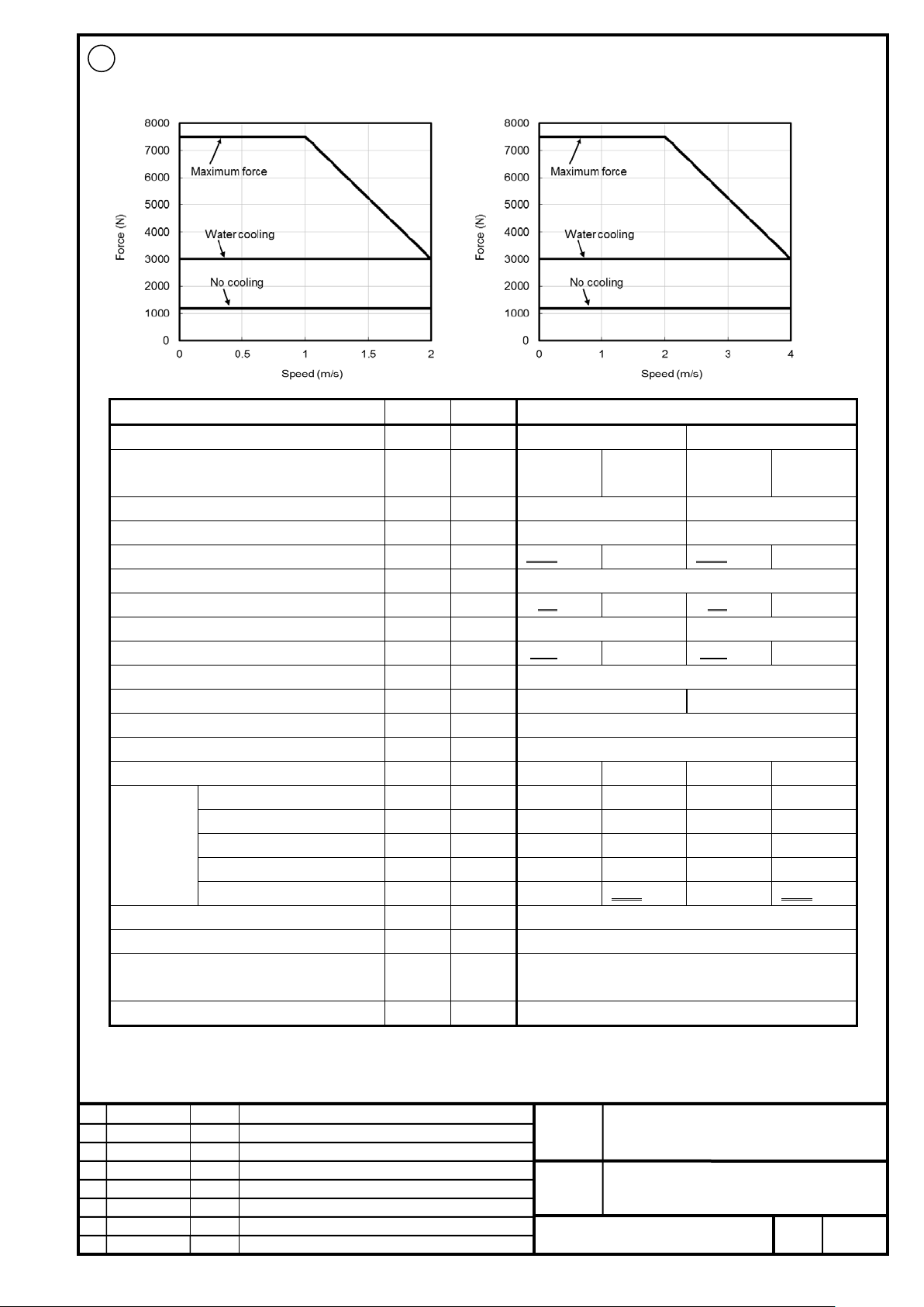
FANUC CORPORATION
Ed
Date
Design
Description
B-65382EN/05-06
Akasako
01
Newly designed
/87
Drawing
Akasako
02
Add M3 model, Correct
Item
Symbol
Unit
Value
Input power voltage
-
V
200
400
cooling
cooling
Maximum speed*3
-
m/s
2
4
Upper speed for the maximum force
-
m/s
1 2 Continuous force *4
Fc
N
1500 1200
3000
1500 1200
3000
Maximum force
FMAX
N
7500
Continuous output
Pc
kW
3.0 2.4
6.0
6.0 4.8
12.0
Maximum output
PMAX
kW 8 16
Continuous current *4
Ic
Arms
12.5 10.0
25.0
12.5 10.0
25.0
Maximum current
IMAX
Arms
88.4
Maximum amplifier current
-
Ap
160
180
Force constant
Kf
N/Arms
119.9
Resistance between terminals
Ra
1.06
Thermal time constant
tt min
60 1 60
1
Coolant *6
- - -
Water
-
Water
Flow rate
-
L/min - 7.5 - 7.5
Recommended pressure
-
MPa - 0.24 - 0.24
Maximum pressure
-
MPa - 0.63 - 0.63
Required cooling capacity
- W -
1500 1250
-
1500 1250
Magnetic attraction *7
Fa
N
22500
Mass of coil slider *8
W
kg
19.6
transportation and storage), non-condensing
Type of applicable magnet plate *10
-
-
M2
02
LiS 7500M2/2-B (A06B-0465-B120#1002)
200V 400V
Cooling method *2 - - No cooling
Water
No cooling
Water
Cooling
conditions
*5
Ω
Use environment *9 - -
Ambient temperature: 0 to 40°C (including during
FANUC LINEAR MOTOR LiS-B series
S1, S2, M2, M3 Model
No.
Page
19
Page 20
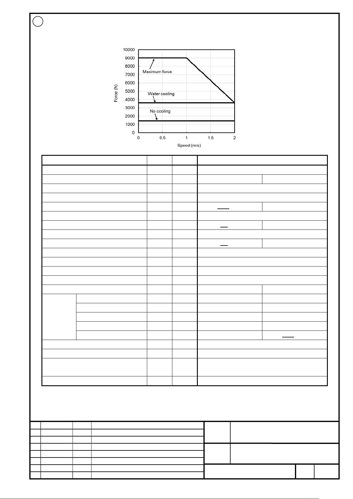
FANUC CORPORATION
Ed
Date
Design
Description
B-65382EN/05-06
Akasako
01
Newly designed
/87
Drawing
Akasako
02
Add M3 model, Correct
Item
Symbol
Unit
Value
Input power voltage
-
V
400
Cooling method *2
- - No cooling
Water cooling
Maximum speed *3
-
m/s 2 Upper speed for the maximum force
-
m/s 1 Continuous force *4
Fc N 1800 1440
3600
Maximum force
FMAX
N
9000
Continuous output
Pc
kW
3.6 2.88
7.2
Maximum output
PMAX
kW
9.6
Continuous current *4
Ic
Arms
6.9 5.52
13.8
Maximum current
IMAX
Arms
48.5
Maximum amplifier current
-
Ap
80
Force constant
Kf
N/Arms
261.45
Resistance between terminals
Ra
4.08
Thermal time constant
tt min
60
1
Coolant *6
-
-
Water
Flow rate
-
L/min
7.5
Recommended pressure
-
MPa
0.28
Maximum pressure
-
MPa
0.63
Required cooling capacity
-
W
1800 1500
Magnetic attraction *7
Fa
N
27000
Mass of coil slider *8
W
kg
23.3
transportation and storage), non-condensing
Type of applicable magnet plate *10
-
-
M2
02
LiS 9000M2/2HV-B (A06B-0466-B020#1002)
400V
Cooling
conditions
*5
Ω
Use environment *9 - -
-
-
-
-
-
Ambient temperature: 0 to 40°C (including during
FANUC LINEAR MOTOR LiS-B series
S1, S2, M2, M3 Model
No.
Page
20
Page 21
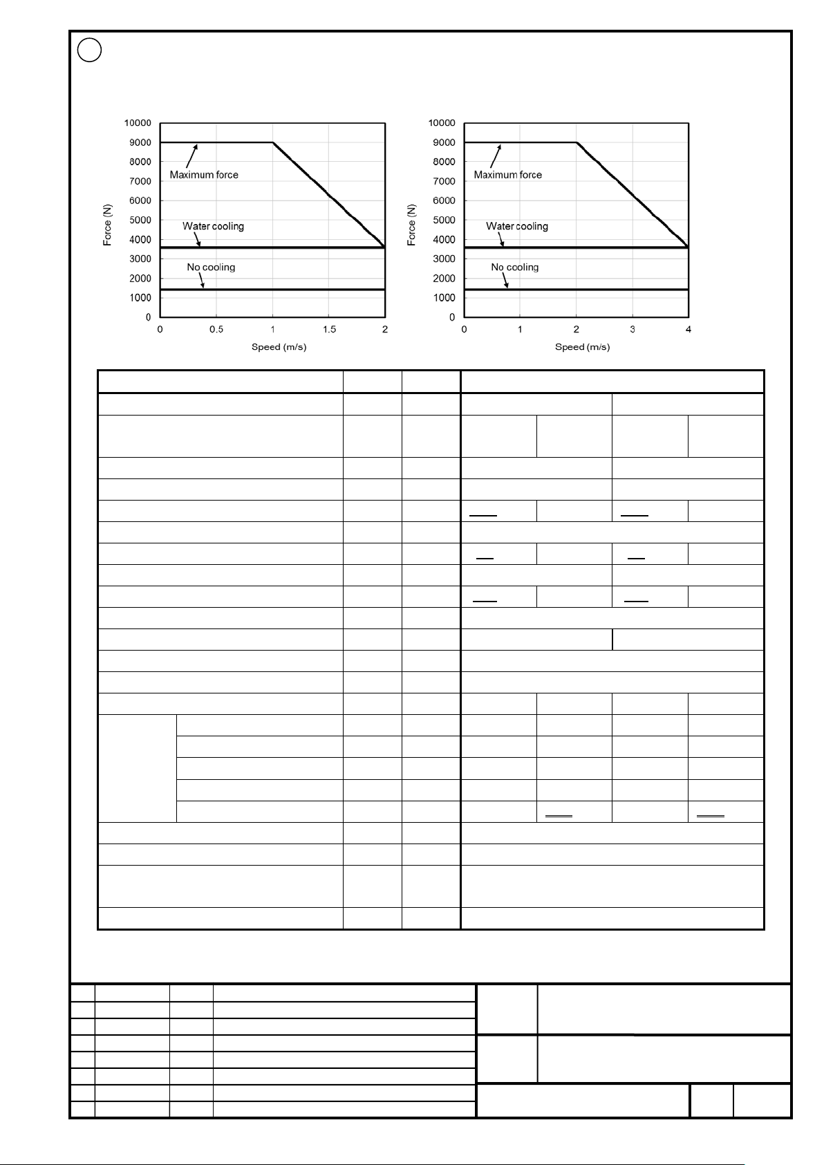
FANUC CORPORATION
Ed
Date
Design
Description
B-65382EN/05-06
Akasako
01
Newly designed
/87
Drawing
Akasako
02
Add M3 model, Correct
Item
Symbol
Unit
Value
Input power voltage
-
V
200
400
cooling
cooling
Maximum speed*3
-
m/s
2
4
Upper speed for the maximum force
-
m/s
1 2 Continuous force *4
Fc
N
1800 1440
3600
1800 1440
3600
Maximum force
FMAX
N
9000
Continuous output
Pc
kW
3.6 2.88
7.2
7.2 5.76
14.4
Maximum output
PMAX
kW
9.6
19.2
Continuous current *4
Ic
Arms
15.0 12.0
30.0
15.0 12.0
30.0
Maximum current
IMAX
Arms
106.0
Maximum amplifier current
-
Ap
160
180
Force constant
Kf
N/Arms
119.9
Resistance between terminals
Ra
0.88
Thermal time constant
tt min
60 1 60
1
Coolant *6
- - -
Water
-
Water
Flow rate
-
L/min - 7.5 - 7.5
Recommended pressure
-
MPa - 0.28 - 0.28
Maximum pressure
-
MPa - 0.63 - 0.63
Required cooling capacity
- W -
1800 1500
-
1800 1500
Magnetic attraction *7
Fa
N
27000
Mass of coil slider *8
W
kg
23.3
transportation and storage), non-condensing
Type of applicable magnet plate *10
-
-
M2
02
LiS 9000M2/2-B (A06B-0466-B120#1002)
200V
400V
Cooling
conditions
*5
Cooling method *2 - - No cooling
Ω
Water
No cooling
Water
Use environment *9 - -
Ambient temperature: 0 to 40°C (including during
FANUC LINEAR MOTOR LiS-B series
S1, S2, M2, M3 Model
No.
Page
21
Page 22
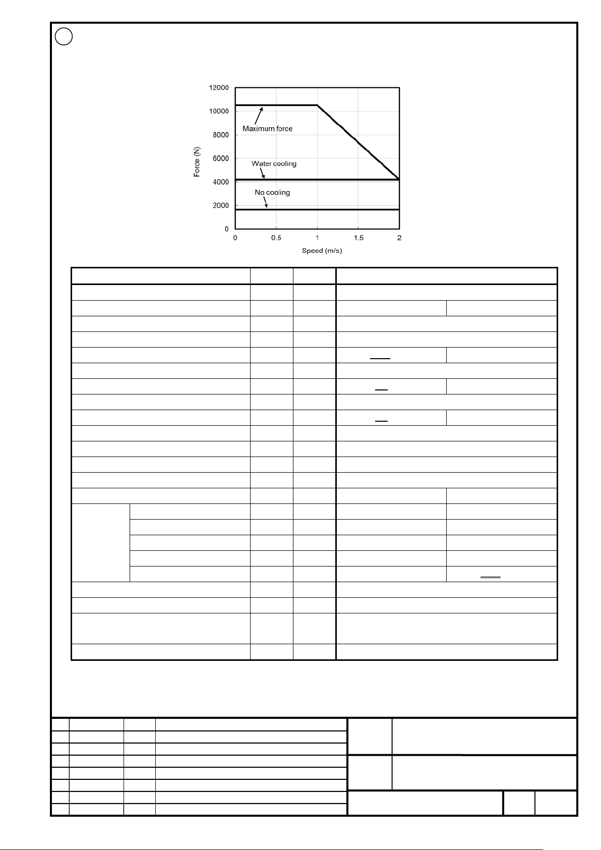
FANUC CORPORATION
Ed
Date
Design
Description
B-65382EN/05-06
Akasako
01
Newly designed
/87
Drawing
Akasako
02
Add M3 model, Correct
Item
Symbol
Unit
Value
Input power voltage
-
V
400
Cooling method *2
- - No cooling
Water cooling
Maximum speed *3
-
m/s 2 Upper speed for the maximum force
-
m/s 1 Continuous force *4
Fc N 2100 1680
4200
Maximum force
FMAX
N
10500
Continuous output
Pc
kW
4.2 3.36
8.4
Maximum output
PMAX
kW
11.2
Continuous current *4
Ic
Arms
8.1 6.48
16.1
Maximum current
IMAX
Arms
56.6
Maximum amplifier current
-
Ap
80
Force constant
Kf
N/Arms
261.5
Resistance between terminals
Ra
3.50
Thermal time constant
tt min
60
1
Coolant *6
-
-
Water
Flow rate
-
L/min
7.5
Recommended pressure
-
MPa
0.39
Maximum pressure
-
MPa
0.63
Required cooling capacity
-
W
2100 1800
Magnetic attraction *7
Fa
N
31500
Mass of coil slider *8
W
kg
27.0
transportation and storage), non-condensing
Type of applicable magnet plate *10
-
-
M2
02
LiS 11000M2/2HV-B (A06B-0467-B020#1002)
400V
Cooling
conditions
*5
Ω
Use environment *9 - -
-
-
-
-
-
Ambient temperature: 0 to 40°C (including during
FANUC LINEAR MOTOR LiS-B series
S1, S2, M2, M3 Model
No.
Page
22
Page 23
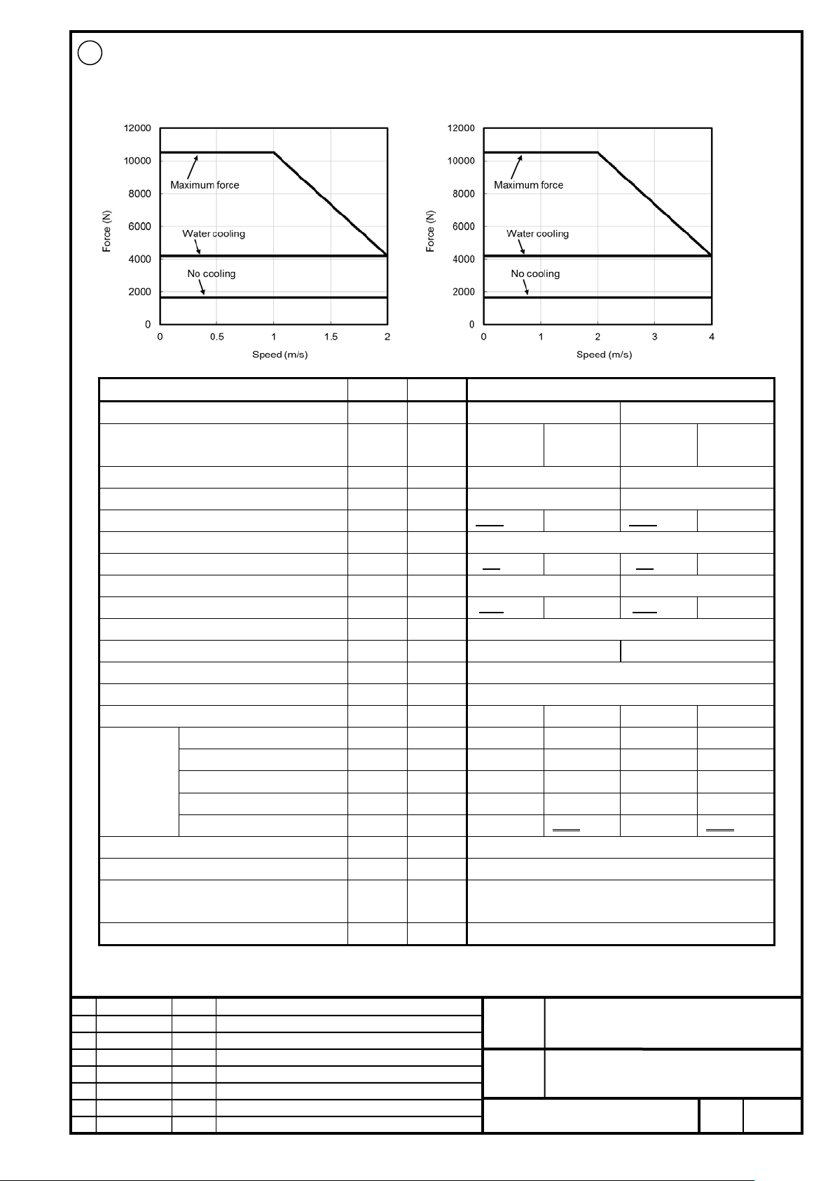
FANUC CORPORATION
Ed
Date
Design
Description
B-65382EN/05-06
Akasako
01
Newly designed
/87
Drawing
Akasako
02
Add M3 model, Correct
Item
Symbol
Unit
Value
Input power voltage
-
V
200
400
cooling
cooling
Maximum speed*3
-
m/s
2
4
Upper speed for the maximum force
-
m/s
1 2 Continuous force *4
Fc
N
2100 1680
4200
2100 1680
4200
Maximum force
FMAX
N
10500
Continuous output
Pc
kW
4.2 3.36
8.4
8.4 6.72
16.8
Maximum output
PMAX
kW
11.2
22.4
Continuous current *4
Ic
Arms
17.5 14.0
35.0
17.5 14.0
35.0
Maximum current
IMAX
Arms
123.7
Maximum amplifier current
-
Ap
360
180
Force constant
Kf
N/Arms
119.9
Resistance between terminals
Ra
Ω
0.76
Thermal time constant
tt min
60 1 60
1
Coolant *6
- - -
Water
-
Water
Flow rate
-
L/min - 7.5 - 7.5
Recommended pressure
-
MPa - 0.39 - 0.39
Maximum pressure
-
MPa - 0.63 - 0.63
Required cooling capacity
- W -
2100 1800
-
2100 1800
Magnetic attraction *7
Fa
N
31500
Mass of coil slider *8
W
kg
27.0
transportation and storage), non-condensing
Type of applicable magnet plate *10
-
-
M2
02
LiS 11000M2/2-B (A06B-0467-B120#1002)
200V
400V
Cooling
conditions
*5
Cooling method *2 - - No cooling
Water
No cooling
Water
Use environment *9 - -
Ambient temperature: 0 to 40°C (including during
FANUC LINEAR MOTOR LiS-B series
S1, S2, M2, M3 Model
No.
Page
23
Page 24

FANUC CORPORATION
Ed
Date
Design
Description
B-65382EN/05-06
Akasako
01
Newly designed
/87
Drawing
Akasako
02
Add M3 model, Correct
Item
Symbol
Unit
Value
Input power voltage
-
V
400
Cooling method *2
- - No cooling
Water cooling
Maximum speed *3
-
m/s 2 Upper speed for the maximum force
-
m/s 1 Continuous force *4
Fc N 720
1800
Maximum force
FMAX
N
4500
Continuous output
Pc
kW
1.4
3.6
Maximum output
PMAX
kW
4.8
Continuous current *4
Ic
Arms
2.8
7.0
Maximum current
IMAX
Arms
23.1
Maximum amplifier current
-
Ap
40
Force constant
Kf
N/Arms
268.4
Resistance between terminals
Ra
8.3
Thermal time constant
tt min
60
1
Coolant *6
-
-
Water
Flow rate
-
L/min
7.5
Recommended pressure
-
MPa
0.16
Maximum pressure
-
MPa
0.63
Required cooling capacity
-
W
750
Magnetic attraction *7
Fa
N
13500
Mass of coil slider *8
W
kg
11.9
transportation and storage), non-condensing
Type of applicable magnet plate *10
-
-
M3
02
LiS 4500M3/2HV-B (A06B-0468-B020#1002)
400V
Cooling
conditions
*5
Ω
Use environment *9 - -
-
-
-
-
-
Ambient temperature: 0 to 40°C (including during
FANUC LINEAR MOTOR LiS-B series
S1, S2, M2, M3 Model
No.
Page
24
Page 25
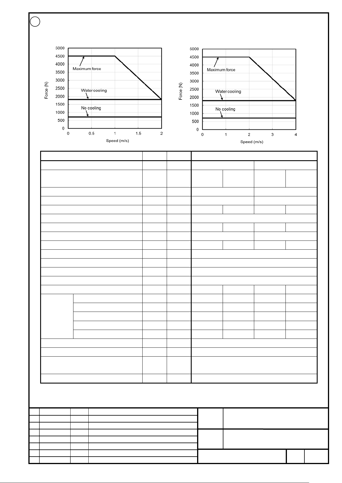
FANUC CORPORATION
Ed
Date
Design
Description
B-65382EN/05-06
Akasako
01
Newly designed
/87
Drawing
Akasako
02
Add M3 model, Correct
Item
Symbol
Unit
Value
Input power voltage
-
V
200
400
cooling
cooling
Maximum speed*3
-
m/s
2
4
Upper speed for the maximum force
-
m/s
1 2 Continuous force *4
Fc N 720
1800
720
1800
Maximum force
FMAX
N
4500
Continuous output
Pc
kW
1.4
3.6
2.9
7.2
Maximum output
PMAX
kW
4.8
9.6
Continuous current *4
Ic
Arms
5.7
14.1
5.7
14.1
Maximum current
IMAX
Arms
46.9
Maximum amplifier current
-
Ap
80
Force constant
Kf
N/Arms
131.8
Resistance between terminals
Ra
2.0
Thermal time constant
tt min
60 1 60
1
Coolant *6
- - -
Water
-
Water
Flow rate
-
L/min - 7.5 - 7.5
Recommended pressure
-
MPa - 0.16 - 0.16
Maximum pressure
-
MPa - 0.63 - 0.63
Required cooling capacity
- W -
750 - 750
Magnetic attraction *7
Fa
N
13500
Mass of coil slider *8
W
kg
11.9
transportation and storage), non-condensing
Type of applicable magnet plate *10
-
-
M3
02
LiS 4500M3/2-B (A06B-0468-B120#1002)
200V
400V
Cooling method *2 - - No cooling
Water
No cooling
Water
Cooling
conditions
*5
Ω
Use environment *9 - -
Ambient temperature: 0 to 40°C (including during
FANUC LINEAR MOTOR LiS-B series
S1, S2, M2, M3 Model
No.
Page
25
Page 26
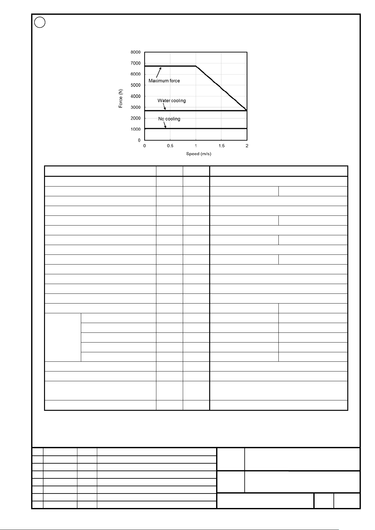
FANUC CORPORATION
Ed
Date
Design
Description
B-65382EN/05-06
Akasako
01
Newly designed
/87
Drawing
Akasako
02
Add M3 model, Correct
Item
Symbol
Unit
Value
Input power voltage
-
V
400
Cooling method *2
- - No cooling
Water cooling
Maximum speed *3
-
m/s 2 Upper speed for the maximum force
-
m/s 1 Continuous force *4
Fc N 1080
2700
Maximum force
FMAX
N
6750
Continuous output
Pc
kW
2.2
5.4
Maximum output
PMAX
kW
7.2
Continuous current *4
Ic
Arms
4.2
10.4
Maximum current
IMAX
Arms
34.6
Maximum amplifier current
-
Ap
80
Force constant
Kf
N/Arms
268.4
Resistance between terminals
Ra
5.5
Thermal time constant
tt min
60
1
Coolant *6
-
-
Water
Flow rate
-
L/min
7.5
Recommended pressure
-
MPa
0.21
Maximum pressure
-
MPa
0.63
Required cooling capacity
-
W
1100
Magnetic attraction *7
Fa
N
20250
Mass of coil slider *8
W
kg
17.1
transportation and storage), non-condensing
Type of applicable magnet plate *10
-
-
M3
02
LiS 7000M3/2HV-B (A06B-0469-B020#1002)
400V
Cooling
conditions
*5
Ω
Use environment *9 - -
-
-
-
-
-
Ambient temperature: 0 to 40°C (including during
FANUC LINEAR MOTOR LiS-B series
S1, S2, M2, M3 Model
No.
Page
26
Page 27

FANUC CORPORATION
Ed
Date
Design
Description
B-65382EN/05-06
Akasako
01
Newly designed
/87
Drawing
Akasako
02
Add M3 model, Correct
Item
Symbol
Unit
Value
Input power voltage
-
V
200
400
cooling
cooling
Maximum speed*3
-
m/s
2
4
Upper speed for the maximum force
-
m/s
1 2 Continuous force *4
Fc N 1080
2700
1080
2700
Maximum force
FMAX
N
6750
Continuous output
Pc
kW
2.2
5.4
4.3
10.8
Maximum output
PMAX
kW
7.2
14.4
Continuous current *4
Ic
Arms
8.5
21.2
8.5
21.2
Maximum current
IMAX
Arms
70.4
Maximum amplifier current
-
Ap
160
180
Force constant
Kf
N/Arms
131.8
Resistance between terminals
Ra
1.3
Thermal time constant
tt min
60 1 60
1
Coolant *6
- - -
Water
-
Water
Flow rate
-
L/min - 7.5 - 7.5
Recommended pressure
-
MPa - 0.21 - 0.21
Maximum pressure
-
MPa - 0.63 - 0.63
Required cooling capacity
- W -
1100
-
1100
Magnetic attraction *7
Fa
N
20250
Mass of coil slider *8
W
kg
17.1
transportation and storage), non-condensing
Type of applicable magnet plate *10
-
-
M3
02
LiS 7000M3/2-B (A06B-0469-B120#1002)
200V 400V
Cooling method *2 - - No cooling
Water
No cooling
Water
Cooling
conditions
*5
Ω
Use environment *9 - -
Ambient temperature: 0 to 40°C (including during
FANUC LINEAR MOTOR LiS-B series
S1, S2, M2, M3 Model
No.
Page
27
Page 28

FANUC CORPORATION
Ed
Date
Design
Description
B-65382EN/05-06
Akasako
01
Newly designed
/87
Drawing
Akasako
02
Add M3 model, Correct
Item
Symbol
Unit
Value
Input power voltage
-
V
200
Cooling method *2
- - No cooling
Water cooling
Maximum speed *3
-
m/s 4 Upper speed for the maximum force
-
m/s 2 Continuous force *4
Fc N 1080
2700
Maximum force
FMAX
N
6750
Continuous output
Pc
kW
4.3
10.8
Maximum output
PMAX
kW
14.4
Continuous current *4
Ic
Arms
16.6
41.6
Maximum current
IMAX
Arms
137.9
Maximum amplifier current
-
Ap
360
Force constant
Kf
N/Arms
67.3
Resistance between terminals
Ra
0.35
Thermal time constant
tt min
60
1
Coolant *6
-
-
Water
Flow rate
-
L/min
7.5
Recommended pressure
-
MPa
0.21
Maximum pressure
-
MPa
0.63
Required cooling capacity
-
W
1100
Magnetic attraction *7
Fa
N
20250
Mass of coil slider *8
W
kg
17.1
transportation and storage), non-condensing
Type of applicable magnet plate *10
-
-
M3
02
LiS 7000M3/4-B (A06B-0469-B220#1002)
400V
Cooling
conditions
*5
Ω
Use environment *9 - -
-
-
-
-
-
Ambient temperature: 0 to 40°C (including during
FANUC LINEAR MOTOR LiS-B series
S1, S2, M2, M3 Model
No.
Page
28
Page 29
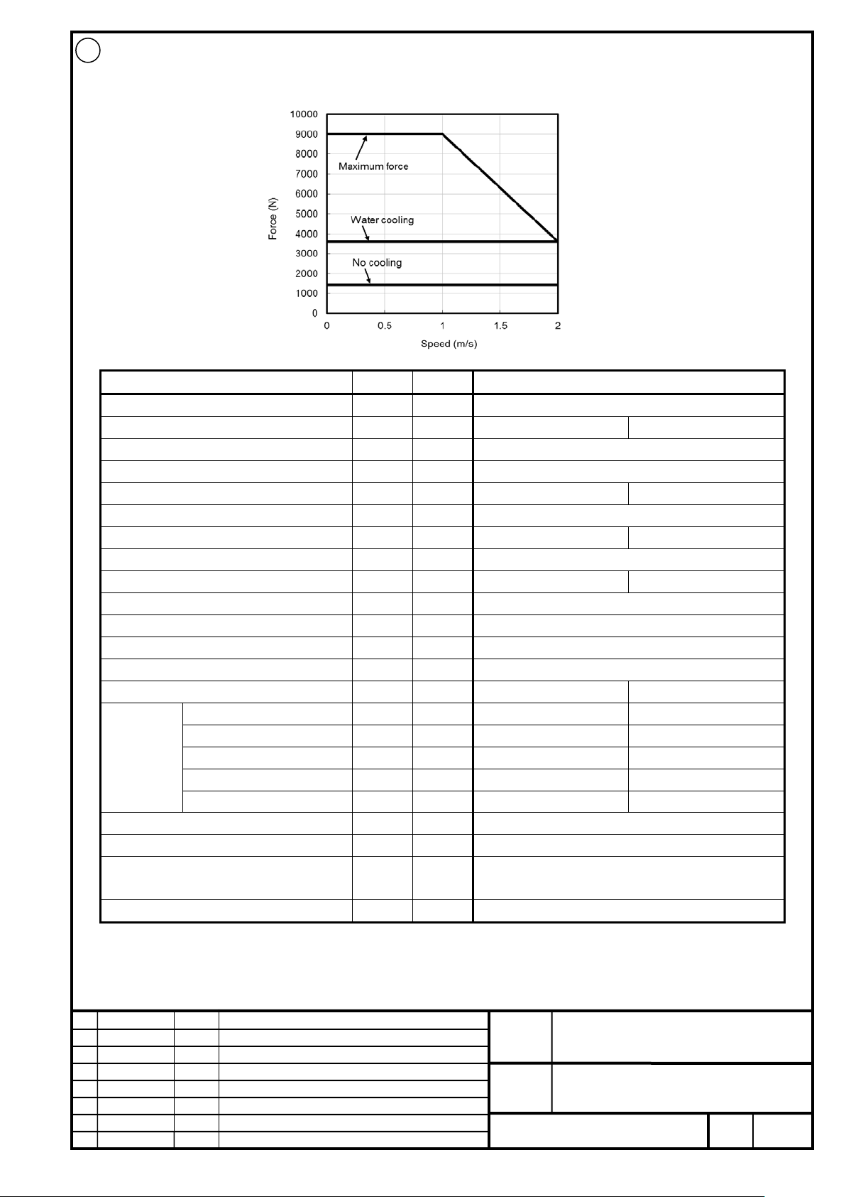
FANUC CORPORATION
Ed
Date
Design
Description
B-65382EN/05-06
Akasako
01
Newly designed
/87
Drawing
Akasako
02
Add M3 model, Correct
Item
Symbol
Unit
Value
Input power voltage
-
V
400
Cooling method *2
- - No cooling
Water cooling
Maximum speed *3
-
m/s 2 Upper speed for the maximum force
-
m/s 1 Continuous force *4
Fc N 1440
3600
Maximum force
FMAX
N
9000
Continuous output
Pc
kW
2.9
7.2
Maximum output
PMAX
kW
9.6
Continuous current *4
Ic
Arms
5.6
13.9
Maximum current
IMAX
Arms
46.1
Maximum amplifier current
-
Ap
80
Force constant
Kf
N/Arms
268.4
Resistance between terminals
Ra
4.1
Thermal time constant
tt min
60
1
Coolant *6
-
-
Water
Flow rate
-
L/min
7.5
Recommended pressure
-
MPa
0.26
Maximum pressure
-
MPa
0.63
Required cooling capacity
-
W
1500
Magnetic attraction *7
Fa
N
27000
Mass of coil slider *8
W
kg
22.4
transportation and storage), non-condensing
Type of applicable magnet plate *10
-
-
M3
02
LiS 9000M3/2HV-B (A06B-0470-B020#1002)
400V
Cooling
conditions
*5
Ω
Use environment *9 - -
-
-
-
-
-
Ambient temperature: 0 to 40°C (including during
FANUC LINEAR MOTOR LiS-B series
S1, S2, M2, M3 Model
No.
Page
29
Page 30
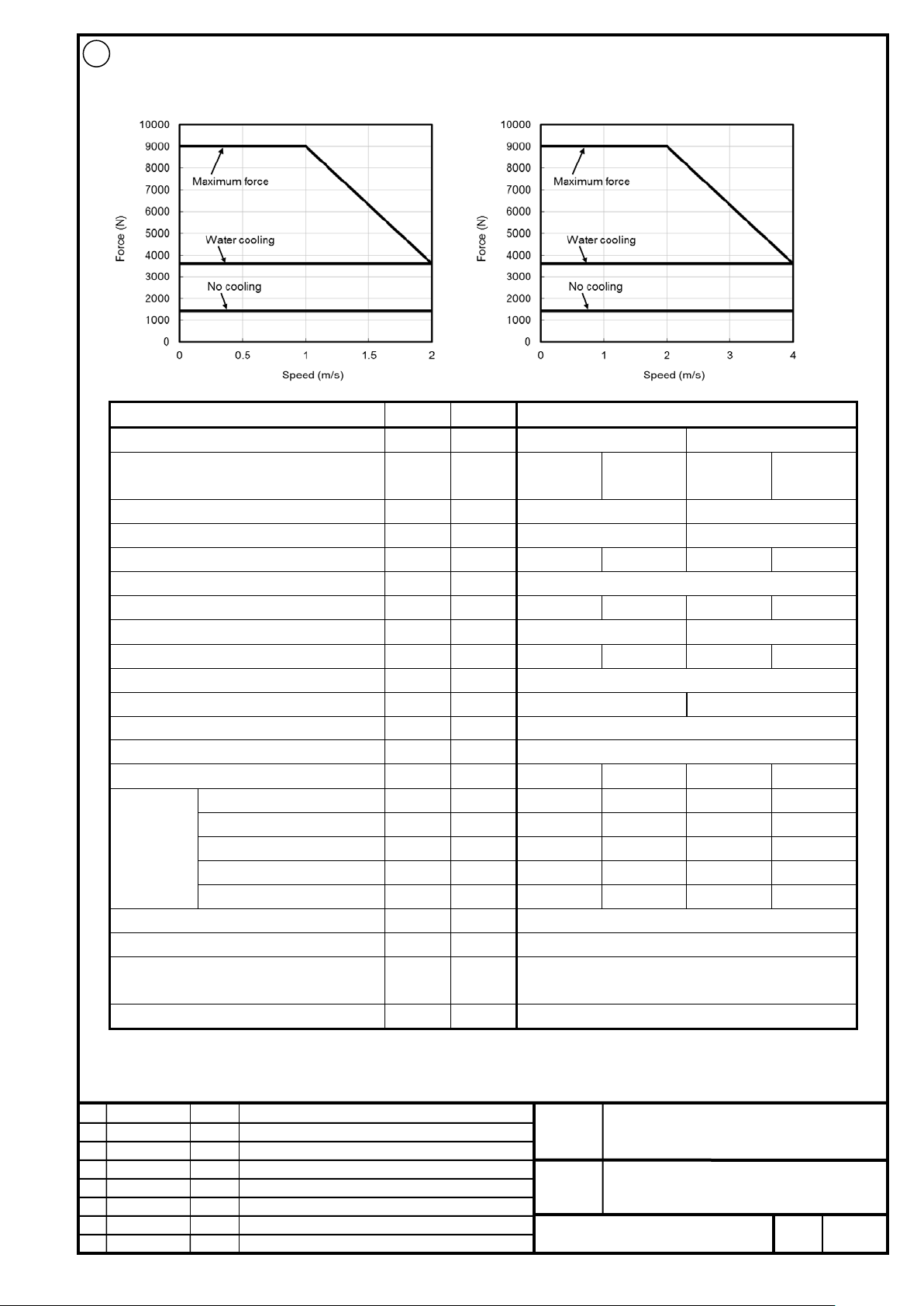
FANUC CORPORATION
Ed
Date
Design
Description
B-65382EN/05-06
Akasako
01
Newly designed
/87
Drawing
Akasako
02
Add M3 model, Correct
Item
Symbol
Unit
Value
Input power voltage
-
V
200
400
cooling
cooling
Maximum speed*3
-
m/s
2
4
Upper speed for the maximum force
-
m/s
1 2 Continuous force *4
Fc N 1440
3600
1440
3600
Maximum force
FMAX
N
9000
Continuous output
Pc
kW
2.9
7.2
5.8
14.4
Maximum output
PMAX
kW
9.6
19.2
Continuous current *4
Ic
Arms
11.3
28.3
11.3
28.3
Maximum current
IMAX
Arms
93.8
Maximum amplifier current
-
Ap
160
180
Force constant
Kf
N/Arms
131.8
Resistance between terminals
Ra
1.0
Thermal time constant
tt min
60 1 60
1
Coolant *6
- - -
Water
-
Water
Flow rate
-
L/min - 7.5 - 7.5
Recommended pressure
-
MPa - 0.26 - 0.26
Maximum pressure
-
MPa - 0.63 - 0.63
Required cooling capacity
- W -
1500
-
1500
Magnetic attraction *7
Fa
N
27000
Mass of coil slider *8
W
kg
22.4
transportation and storage), non-condensing
Type of applicable magnet plate *10
-
-
M3
02
LiS 9000M3/2-B (A06B-0470-B120#1002)
200V
400V
Cooling
conditions
*5
Cooling method *2 - - No cooling
Ω
Water
No cooling
Water
Use environment *9 - -
Ambient temperature: 0 to 40°C (including during
FANUC LINEAR MOTOR LiS-B series
S1, S2, M2, M3 Model
No.
Page
30
Page 31
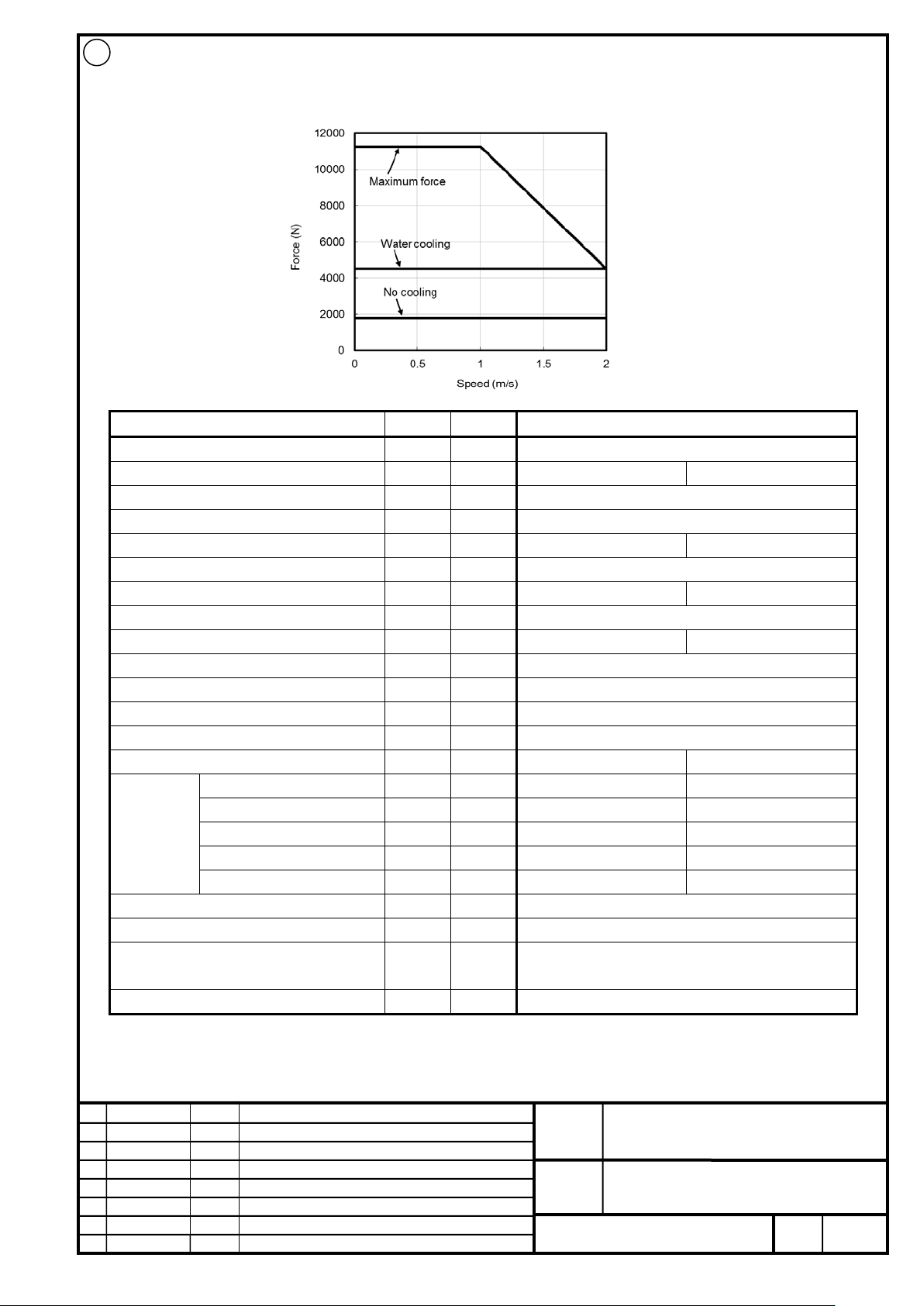
FANUC CORPORATION
Ed
Date
Design
Description
B-65382EN/05-06
Akasako
01
Newly designed
/87
Drawing
Akasako
02
Add M3 model, Correct
Item
Symbol
Unit
Value
Input power voltage
-
V
400
Cooling method *2
- - No cooling
Water cooling
Maximum speed *3
-
m/s 2 Upper speed for the maximum force
-
m/s 1 Continuous force *4
Fc N 1800
4500
Maximum force
FMAX
N
11250
Continuous output
Pc
kW
3.6
9.0
Maximum output
PMAX
kW
12.0
Continuous current *4
Ic
Arms
7.0
17.4
Maximum current
IMAX
Arms
56.6
Maximum amplifier current
-
Ap
80
Force constant
Kf
N/Arms
268.4
Resistance between terminals
Ra
3.3
Thermal time constant
tt min
60
1
Coolant *6
-
-
Water
Flow rate
-
L/min
7.5
Recommended pressure
-
MPa
0.32
Maximum pressure
-
MPa
0.63
Required cooling capacity
-
W
1900
Magnetic attraction *7
Fa
N
33750
Mass of coil slider *8
W
kg
27.7
transportation and storage), non-condensing
Type of applicable magnet plate *10
-
-
M3
02
LiS 11000M3/2HV-B (A06B-0471-B020#1002)
400V
Cooling
conditions
*5
Ω
Use environment *9 - -
-
-
-
-
-
Ambient temperature: 0 to 40°C (including during
FANUC LINEAR MOTOR LiS-B series
S1, S2, M2, M3 Model
No.
Page
31
Page 32
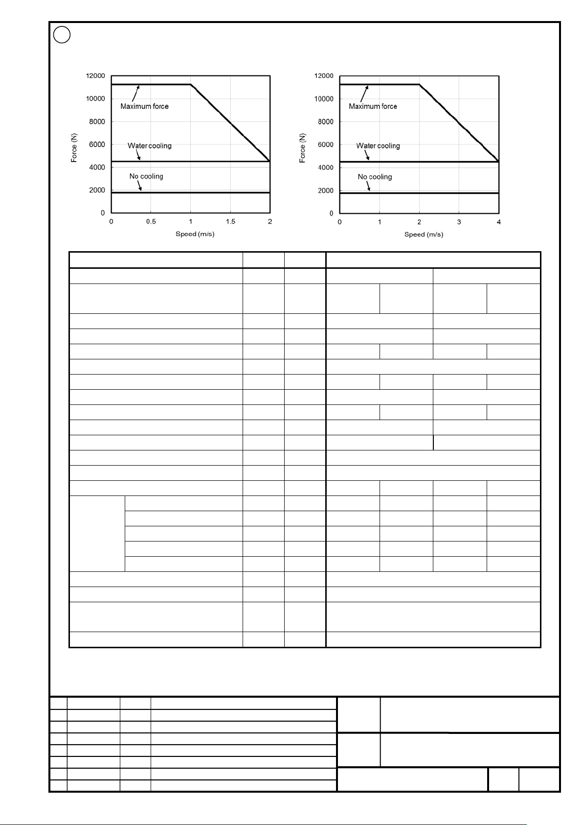
FANUC CORPORATION
Ed
Date
Design
Description
B-65382EN/05-06
Akasako
01
Newly designed
/87
Drawing
Akasako
02
Add M3 model, Correct
Item
Symbol
Unit
Value
Input power voltage
-
V
200
400
cooling
cooling
Maximum speed*3
-
m/s
2
4
Upper speed for the maximum force
-
m/s
1 2 Continuous force *4
Fc N 1800
4500
1800
4500
Maximum force
FMAX
N
11250
Continuous output
Pc
kW
3.6
9.0
7.2
18.0
Maximum output
PMAX
kW
12.0
24.0
Continuous current *4
Ic
Arms
14.1
35.4
14.1
35.4
Maximum current
I
Arms
113.1
117.3
Maximum amplifier current
-
Ap
160
180
Force constant
Kf
N/Arms
131.8
Resistance between terminals
Ra
0.80
Thermal time constant
tt min
60 1 60
1
Coolant *6
- - -
Water
-
Water
Flow rate
-
L/min - 7.5 - 7.5
Recommended pressure
-
MPa - 0.32 - 0.32
Maximum pressure
-
MPa - 0.63 - 0.63
Required cooling capacity
- W -
1900
-
1900
Magnetic attraction *7
Fa
N
33750
Mass of coil slider *8
W
kg
27.7
transportation and storage), non-condensing
Type of applicable magnet plate *10
-
-
M3
02
LiS 11000M3/2-B (A06B-0471-B120#1002)
200V 400V
Cooling method *2 - - No cooling
Water
No cooling
Water
Cooling
conditions
*5
MAX
Ω
Use environment *9 - -
Ambient temperature: 0 to 40°C (including during
FANUC LINEAR MOTOR LiS-B series
S1, S2, M2, M3 Model
No.
Page
32
Page 33
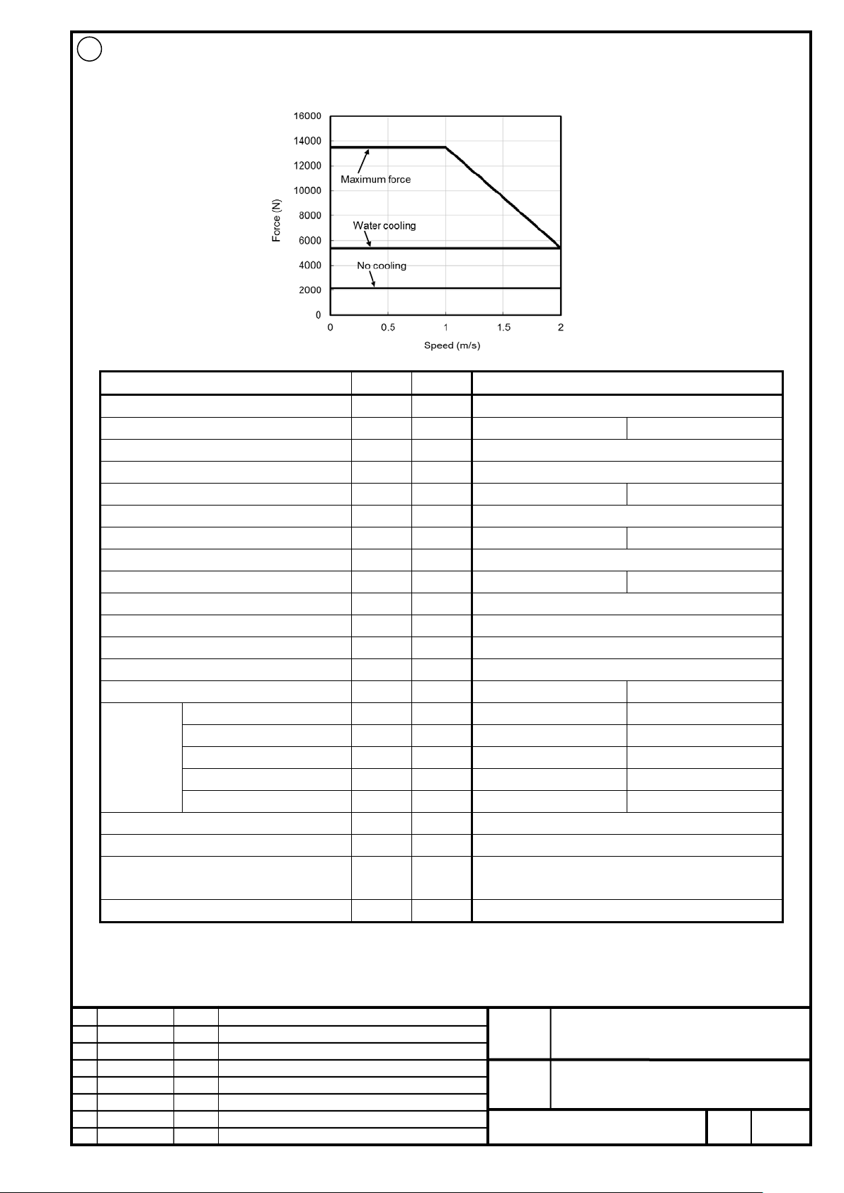
FANUC CORPORATION
Ed
Date
Design
Description
B-65382EN/05-06
Akasako
01
Newly designed
/87
Drawing
Akasako
02
Add M3 model, Correct
Item
Symbol
Unit
Value
Input power voltage
-
V
400
Cooling method *2
- - No cooling
Water cooling
Maximum speed *3
-
m/s 2 Upper speed for the maximum force
-
m/s 1 Continuous force *4
Fc N 2160
5400
Maximum force
FMAX
N
13500
Continuous output
Pc
kW
4.3
10.8
Maximum output
PMAX
kW
14.4
Continuous current *4
Ic
Arms
7.8
20.2
Maximum current
IMAX
Arms
69.2
Maximum amplifier current
-
Ap
180
Force constant
Kf
N/Arms
268.4
Resistance between terminals
Ra
2.8
Thermal time constant
tt min
60
1
Coolant *6
-
-
Water
Flow rate
-
L/min
7.5
Recommended pressure
-
MPa
0.38
Maximum pressure
-
MPa
0.63
Required cooling capacity
-
W
2300
Magnetic attraction *7
Fa
N
40500
Mass of coil slider *8
W
kg
32.8
transportation and storage), non-condensing
Type of applicable magnet plate *10
-
-
M3
02
LiS 14000M3/2HV-B (A06B-0472-B020#1002)
400V
Cooling
conditions
*5
Ω
Use environment *9 - -
-
-
-
-
-
Ambient temperature: 0 to 40°C (including during
FANUC LINEAR MOTOR LiS-B series
S1, S2, M2, M3 Model
No.
Page
33
Page 34

FANUC CORPORATION
Ed
Date
Design
Description
B-65382EN/05-06
Akasako
01
Newly designed
/87
Drawing
Akasako
02
Add M3 model, Correct
Item
Symbol
Unit
Value
Input power voltage
-
V
200
400
cooling
cooling
Maximum speed*3
-
m/s
2
4
Upper speed for the maximum force
-
m/s
1 2 Continuous force *4
Fc N 2160
5400
2160
5400
Maximum force
FMAX
N
13500
Continuous output
Pc
kW
4.3
10.8
8.6
21.6
Maximum output
PMAX
kW
14.4
28.8
Continuous current *4
Ic
Arms
15.8
41.0
15.8
41.0
Maximum current
IMAX
Arms
140.7
Maximum amplifier current
-
Ap
360
Force constant
Kf
N/Arms
131.8
Resistance between terminals
Ra
0.66
Thermal time constant
tt min
60 1 60
1
Coolant *6
- - -
Water
-
Water
Flow rate
-
L/min - 7.5 - 7.5
Recommended pressure
-
MPa - 0.38 - 0.38
Maximum pressure
-
MPa - 0.63 - 0.63
Required cooling capacity
- W -
2300
-
2300
Magnetic attraction *7
Fa
N
40500
Mass of coil slider *8
W
kg
32.8
transportation and storage), non-condensing
Type of applicable magnet plate *10
-
-
M3
02
LiS 14000M3/2-B (A06B-0472-B120#1002)
200V
400V
Cooling
conditions
*5
Cooling method *2 - - No cooling
Ω
Water
No cooling
Water
Use environment *9 - -
Ambient temperature: 0 to 40°C (including during
FANUC LINEAR MOTOR LiS-B series
S1, S2, M2, M3 Model
No.
Page
34
Page 35
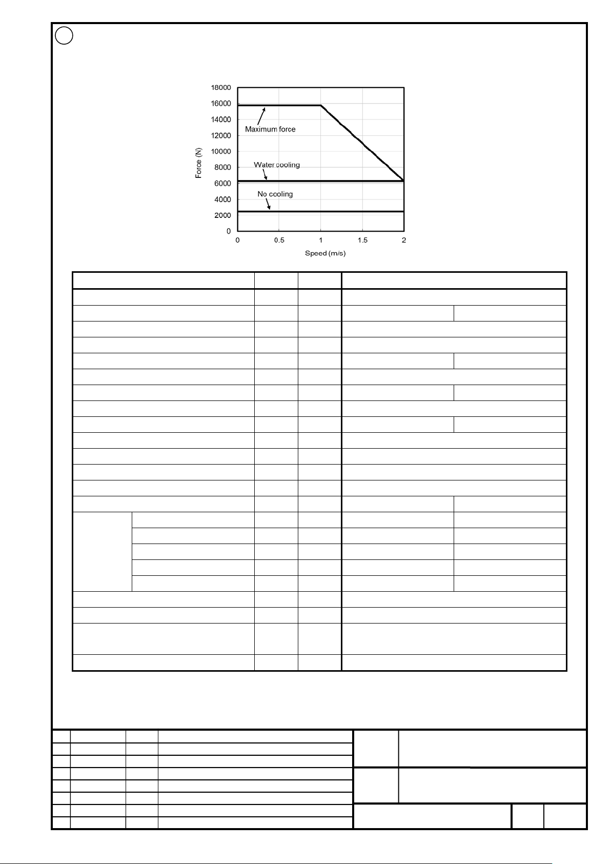
FANUC CORPORATION
Ed
Date
Design
Description
B-65382EN/05-06
Akasako
01
Newly designed
/87
Drawing
Akasako
02
Add M3 model, Correct
Item
Symbol
Unit
Value
Input power voltage
-
V
400
Cooling method *2
- - No cooling
Water cooling
Maximum speed *3
-
m/s 2 Upper speed for the maximum force
-
m/s 1 Continuous force *4
Fc N 2520
6300
Maximum force
FMAX
N
15750
Continuous output
Pc
kW
5.0
12.6
Maximum output
PMAX
kW
16.8
Continuous current *4
Ic
Arms
9.5
24.3
Maximum current
IMAX
Arms
80.7
Maximum amplifier current
-
Ap
180
Force constant
Kf
N/Arms
268.4
Resistance between terminals
Ra
2.4
Thermal time constant
tt min
60
1
Coolant *6
-
-
Water
Flow rate
-
L/min
7.5
Recommended pressure
-
MPa
0.44
Maximum pressure
-
MPa
0.63
Required cooling capacity
-
W
2700
Magnetic attraction *7
Fa
N
47250
Mass of coil slider *8
W
kg
37.8
transportation and storage), non-condensing
Type of applicable magnet plate *10
-
-
M3
02
LiS 16000M3/2HV-B (A06B-0473-B020#1002)
400V
Cooling
conditions
*5
Ω
Use environment *9 - -
-
-
-
-
-
Ambient temperature: 0 to 40°C (including during
FANUC LINEAR MOTOR LiS-B series
S1, S2, M2, M3 Model
No.
Page
35
Page 36
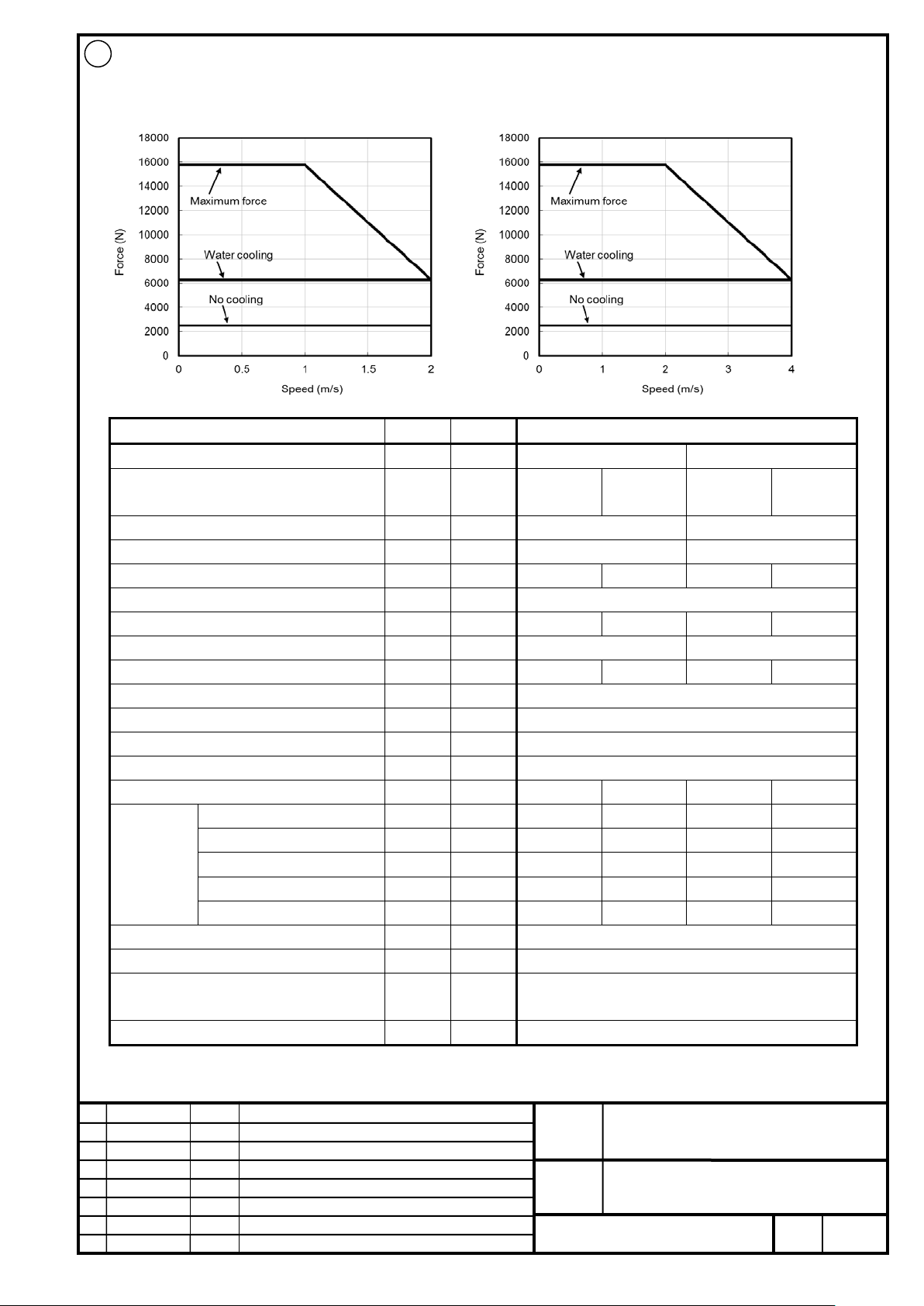
FANUC CORPORATION
Ed
Date
Design
Description
B-65382EN/05-06
Akasako
01
Newly designed
/87
Drawing
Akasako
02
Add M3 model, Correct
Item
Symbol
Unit
Value
Input power voltage
-
V
200
400
cooling
cooling
Maximum speed*3
-
m/s
2
4
Upper speed for the maximum force
-
m/s
1 2 Continuous force *4
Fc N 2520
6300
2520
6300
Maximum force
FMAX
N
15750
Continuous output
Pc
kW
5.0
12.6
10.1
25.2
Maximum output
PMAX
kW
16.8
33.6
Continuous current *4
Ic
Arms
19.3
49.5
19.3
49.5
Maximum current
IMAX
Arms
164.2
Maximum amplifier current
-
Ap
360
Force constant
Kf
N/Arms
131.8
Resistance between terminals
Ra
Ω
0.56
Thermal time constant
tt min
60 1 60
1
Coolant *6
- - -
Water
-
Water
Flow rate
-
L/min - 7.5 - 7.5
Recommended pressure
-
MPa - 0.44 - 0.44
Maximum pressure
-
MPa - 0.63 - 0.63
Required cooling capacity
- W -
2700
-
2700
Magnetic attraction *7
Fa
N
47250
Mass of coil slider *8
W
kg
37.8
transportation and storage), non-condensing
Type of applicable magnet plate *10
-
-
M3
02
LiS 16000M3/2-B (A06B-0473-B120#1002)
200V
400V
Cooling
conditions
*5
Cooling method *2 - - No cooling
Water
No cooling
Water
Use environment *9 - -
Ambient temperature: 0 to 40°C (including during
FANUC LINEAR MOTOR LiS-B series
S1, S2, M2, M3 Model
No.
Page
36
Page 37

FANUC CORPORATION
Ed
Date
Design
Description
B-65382EN/05-06
Akasako
01
Newly designed
/87
Drawing
Akasako
02
Add M3 model, Correct
10 The type of applicable magnet plate differs depending on the motor model.
NOTE
1 The values are standard values at 25°C and the specified input power voltage. The values may vary
depending on the ambient temperature, digital servo software, parameter s, power supply voltage, servo
amplifier specifications, linear encoder specifications, and others.
2
2.1 For S1, S2 model
To use "water cooling," a forced cooling with a cooling plate (option) is required. For details, refer to
Subsection 7-4, “Cooling Plate.”
2.2 For M2, M3 model
For no cooling, the built-in cooling tube of coil slider is not used. For water cooling, forced cooling with
the built-in cooling tube is required.
3 Since the speed of the feed axis is limited by the speed restriction value that depends on the the internal
processing of system and the internal processing of serv o s oftware, the listed maximum speeds are not
guaranteed for all linear encoders.
4 The value is at motor moving. It is limit ed s eparately at motor locked.
5 For no cooling, the rating may depend on the heat capacity determined by the the material around the c oi l
slider and the structure of the machine.
6 Primary coolant for forced cooling (coolant for directly cooling the coi l slider). "Water" indicates soft water or
ion exchanged water (containing a rust inhibitor).
7 This is the maximum value of magnetic attract ion between the coil slider and the magnet plate. This value
varies depending on the gap.
8 When the incremental linear encoder is used, the weight of the magnetic pole sensor i s added.
In the case of water cooling at S1, S2 model, the weight of the cooling plate is added. For details, refer to
Subsection 7-4, “Cooling Plate.”
9 Dustproof and water proof protection is required.
For M2, M3 model
When the power line and signal cable are connected in the specified method, the protect ion l ev el of
connector section in the engagement state is equivalent to IP67.
FANUC LINEAR MOTOR LiS-B series
S1, S2, M2, M3 Model
No.
Page
37
Page 38
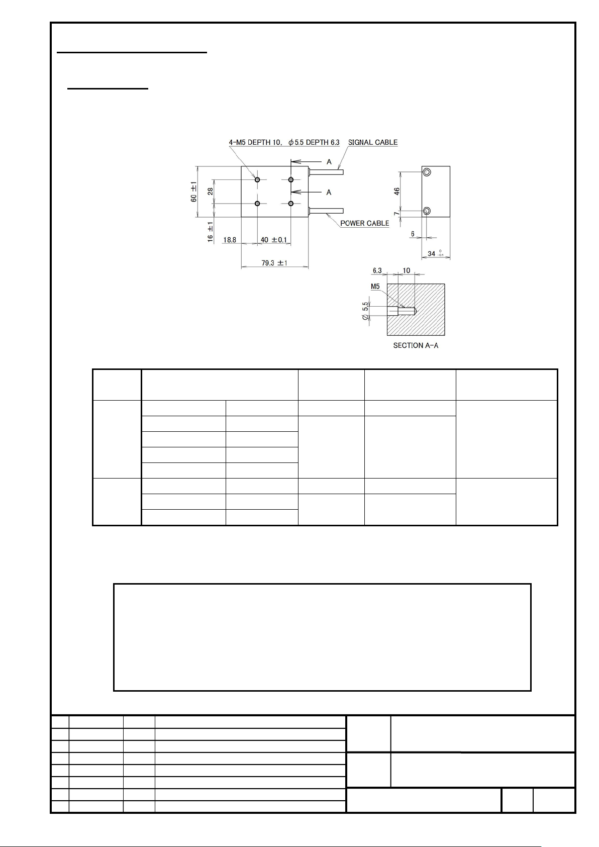
FANUC CORPORATION
Ed
Date
Design
Description
B-65382EN/05-06
Akasako
01
Newly designed
/87
Drawing
Akasako
02
Add M3 model, Correct
size
(mm)
radius (mm)
Sheath
Orange
-
∅5.7~∅6.3
U phase
Red
V phase
White
W phase
Black
Ground
Yellow / Green
Sheath
Black
-
∅4.9~∅5.5
PTC thermistor
Red / White
NTC thermistor
Blue / Brown
4 To use water cooling, the cooling plate (optional) is required separately.
7. EXTERNAL DIMENSION
7-1 Coil Slider
LiS 300S1/4-B (A06B-0424-B200#1002)
Power
line
Signal
line
* The power and signal lines are about 1000mm long.
* The PTC thermistor and NTC thermis tor lines are non-polarized.
* The power and signal lines are intended to be used for a fixed section. When the coil slider is movable, be sure
to connect it to a movable relay cable.
NOTE
1 In this model, power line is cabtyre cable type.
2 This drawing contains no magnetic pole sensor. To use an incremental li near encoder, a
magnetic pole sensor is required.
3 The surface opposite to the magnet plate is not mac hi ned. If the surface is ground for
adjustment of the thickness or other purposes, the insulation performance may degrade.
Color
Conductor
16 AWG ∅2.1
24 AWG ∅1.3
Outer diameter
Minimum bending
30
31
No.
FANUC LINEAR MOTOR LiS-B series
S1, S2, M2, M3 Model
Page
38
Page 39

FANUC CORPORATION
Ed
Date
Design
Description
B-65382EN/05-06
Akasako
01
Newly designed
/87
Drawing
Akasako
02
Add M3 model, Correct
size
(mm)
radius (mm)
Sheath
Orange
-
∅5.7~∅6.3
U phase
Red
V phase
White
W phase
Black
Ground
Yellow / Green
Sheath
Black
-
∅4.9~∅5.5
PTC thermistor
Red / White
NTC thermistor
Blue / Brown
4 To use water cooling, the cooling plate (optional) is required separat el y.
LiS 600S1/4-B (A06B-0425-B200#1002)
Color
Conductor
Outer diameter
Minimum bending
Power
line
Signal
line
* The power and signal lines are about 1000mm long.
* The PTC thermistor and NTC therm i s tor lines are non-polarized.
* The power and signal lines are intended to be used for a fixed section. When the coil slider is movable, be sur e
to connect it to a movable relay cable.
NOTE
1 In this model, power line is cabtyre cable type.
2 This drawing contains no magnetic pole sensor. To use an incremental li near encoder, a
magnetic pole sensor is required.
3 The surface opposite to the magnet plate is not mac hi ned. If the surface is ground for
adjustment of the thickness or other purposes, the insulation performance may degrade.
16 AWG ∅2.1
24 AWG ∅1.3
30
31
No.
FANUC LINEAR MOTOR LiS-B series
S1, S2, M2, M3 Model
Page
39
Page 40
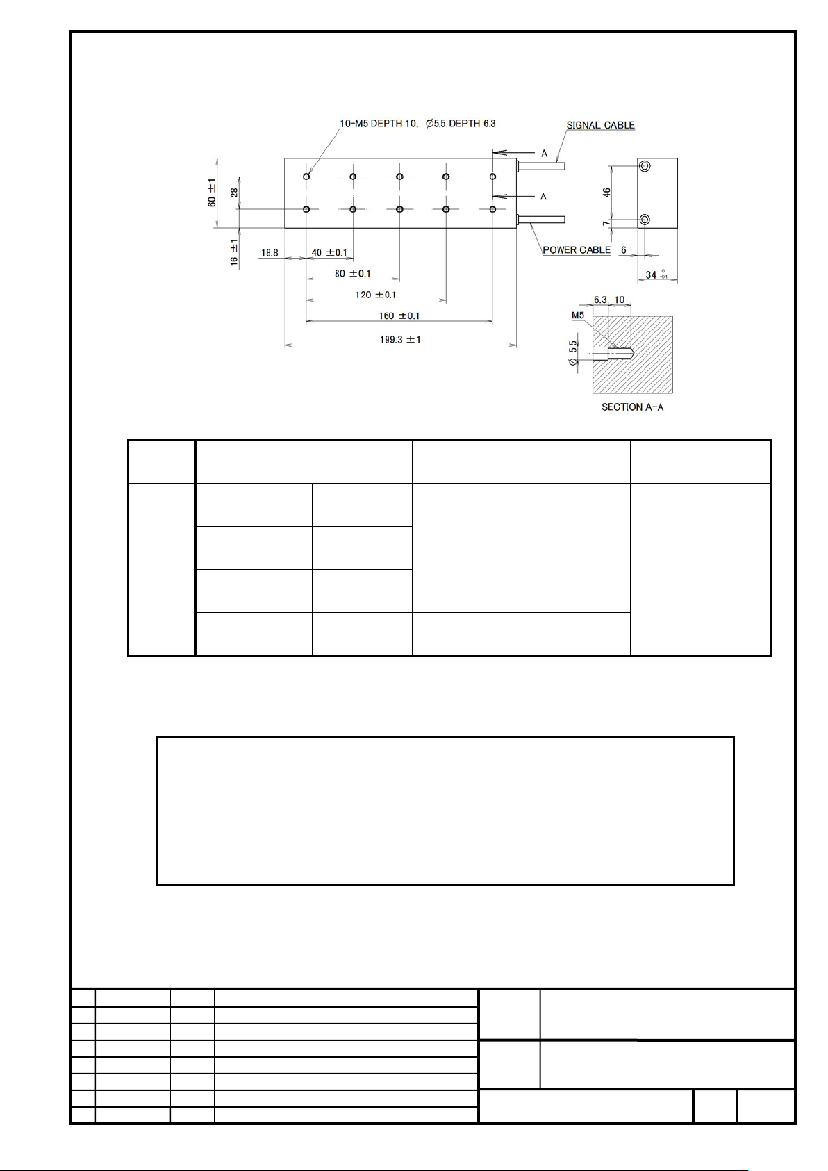
FANUC CORPORATION
Ed
Date
Design
Description
B-65382EN/05-06
Akasako
01
Newly designed
/87
Drawing
Akasako
02
Add M3 model, Correct
size
(mm)
radius (mm)
Sheath
Orange
-
∅5.7~∅6.3
U phase
Red
V phase
White
W phase
Black
Ground
Yellow / Green
Sheath
Black
-
∅4.9~∅5.5
PTC thermistor
Red / White
NTC thermistor
Blue / Brown
4 To use water cooling, the cooling plate (optional) is required separatel y.
LiS 900S1/4-B (A06B-0426-B200#1002)
Color
Conductor
Outer diameter
Minimum bending
Power
line
Signal
line
* The power and signal lines are about 1000mm long.
* The PTC thermistor and NTC therm i s tor lines are non-polarized.
* The power and signal lines are intended to be used for a fixed section. When the coil slider is movable, be sure
to connect it to a movable relay cable.
NOTE
1 In this model, power line is cabtyre cable type.
2 This drawing contains no magnetic pole sensor. To use an incremental linear encoder, a
magnetic pole sensor is required.
3 The surface opposite to the magnet plate is not mac hi ned. If the surface is ground for
adjustment of the thickness or other purposes, the insulation performance may degrade.
16 AWG ∅2.1
24 AWG ∅1.3
30
31
No.
FANUC LINEAR MOTOR LiS-B series
S1, S2, M2, M3 Model
Page
40
Page 41
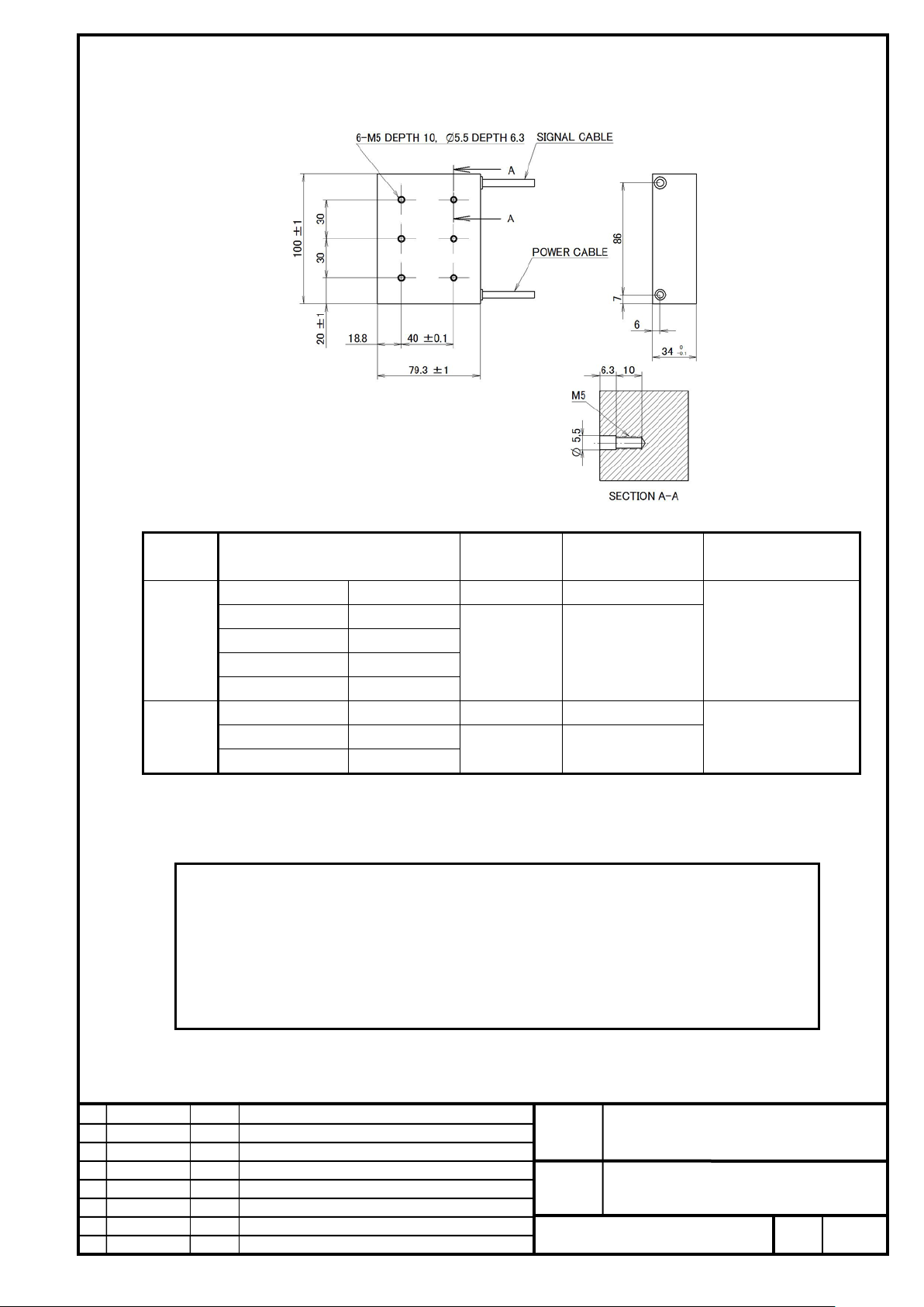
FANUC CORPORATION
Ed
Date
Design
Description
B-65382EN/05-06
Akasako
01
Newly designed
/87
Drawing
Akasako
02
Add M3 model, Correct
size
(mm)
radius (mm)
Sheath
Orange
-
∅5.7~∅6.3
U phase
Red
V phase
White
W phase
Black
Ground
Yellow / Green
Sheath
Black
-
∅4.9~∅5.5
PTC thermistor
Red / White
NTC thermistor
Blue / Brown
4 To use water cooling, the cooling plate (optional) is required separately.
LiS 600S2/3-B (A06B-0427-B200#1002)
Power
line
Signal
line
* The power and signal lines are about 1000mm long.
* The PTC thermistor and NTC therm i s tor lines are non-polarized.
* The power and signal lines are intended to be used for a fixed section. When the coil slider is movable, be sur e
to connect it to a movable relay cable.
NOTE
1 In this model, power line is cabtyre cable type.
2 This drawing contains no magnetic pole sensor. To use an incremental li near encoder, a
magnetic pole sensor is required.
3 The surface opposite to the magnet plate is not mac hi ned. If the surface is ground for
adjustment of the thickness or other purposes, the insulation performance may degrade.
Color
Conductor
16 AWG ∅2.1
24 AWG ∅1.3
Outer diameter
Minimum bending
30
31
No.
FANUC LINEAR MOTOR LiS-B series
S1, S2, M2, M3 Model
Page
41
Page 42
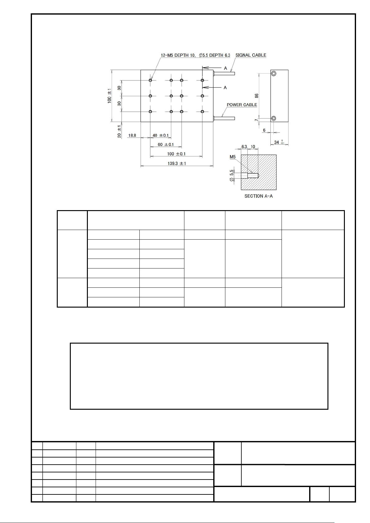
FANUC CORPORATION
Ed
Date
Design
Description
B-65382EN/05-06
Akasako
01
Newly designed
/87
Drawing
Akasako
02
Add M3 model, Correct
size
(mm)
radius (mm)
Sheath
Orange
-
∅5.7~∅6.3
U phase
Red
V phase
White
W phase
Black
Ground
Yellow / Green
Sheath
Black
-
∅4.9~∅5.5
PTC thermistor
Red / White
NTC thermistor
Blue / Brown
4 To use water cooling, the cooling plate (optional) is required separatel y.
LiS 1200S2/3-B (A06B-0428-B200#1002)
Color
Conductor
Outer diameter
Minimum bending
Power
line
Signal
line
* The power and signal lines are about 1000mm long.
* The PTC thermistor and NTC therm i s tor lines are non-polarized.
* The power and signal lines are intended to be used for a fixed section. When the coil slider is movable, be sure
to connect it to a movable relay cable.
NOTE
1 In this model, power line is cabtyre cable type.
2 This drawing contains no magnetic pole sensor. To use an incremental linear encoder, a
magnetic pole sensor is required.
3 The surface opposite to the magnet plate is not mac hi ned. If the surface is ground for
adjustment of the thickness or other purposes, the insulation performance may degrade.
16 AWG ∅2.1
24 AWG ∅1.3
30
31
No.
FANUC LINEAR MOTOR LiS-B series
S1, S2, M2, M3 Model
Page
42
Page 43
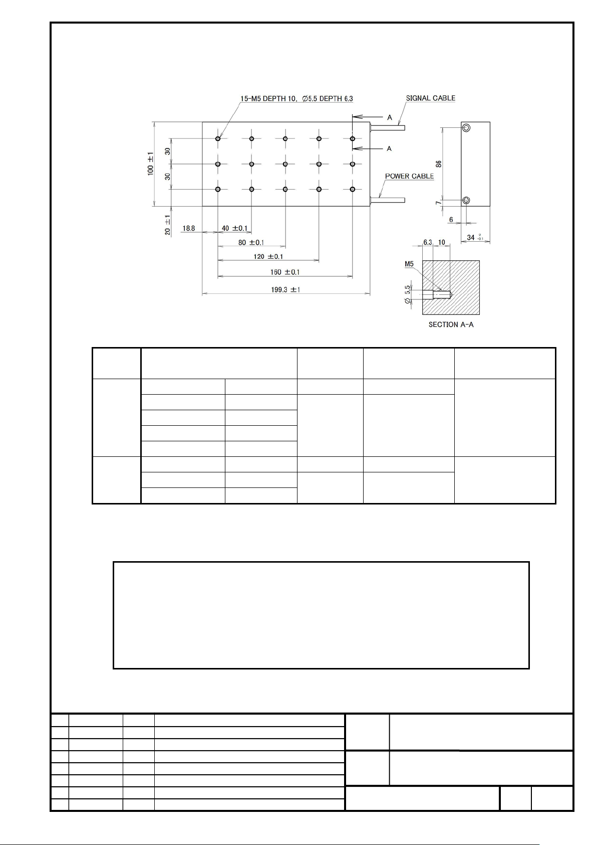
FANUC CORPORATION
Ed
Date
Design
Description
B-65382EN/05-06
Akasako
01
Newly designed
/87
Drawing
Akasako
02
Add M3 model, Correct
size
(mm)
radius (mm)
Sheath
Orange
-
∅5.7~∅6.3
U phase
Red
V phase
White
W phase
Black
Ground
Yellow / Green
Sheath
Black
-
∅4.9~∅5.5
PTC thermistor
Red / White
NTC thermistor
Blue / Brown
4 To use water cooling, the cooling plate (optional) is required separately.
LiS 1800S2/3-B (A06B-0429-B200#1002)
Power
line
Signal
line
* The power and signal lines are about 1000mm long.
* The PTC thermistor and NTC therm i s tor lines are non-polarized.
* The power and signal lines are intended to be used for a fixed section. When the coil slider is movable, be sur e
to connect it to a movable relay cable.
NOTE
1 In this model, power line is cabtyre cable type.
2 This drawing contains no magnetic pole sensor. To use an incremental li near encoder, a
magnetic pole sensor is required.
3 The surface opposite to the magnet plate is not mac hi ned. If the surface is ground for
adjustment of the thickness or other purposes, the insulation performance may degrade.
Color
Conductor
16 AWG ∅2.1
24 AWG ∅1.3
Outer diameter
Minimum bending
30
31
No.
FANUC LINEAR MOTOR LiS-B series
S1, S2, M2, M3 Model
Page
43
Page 44
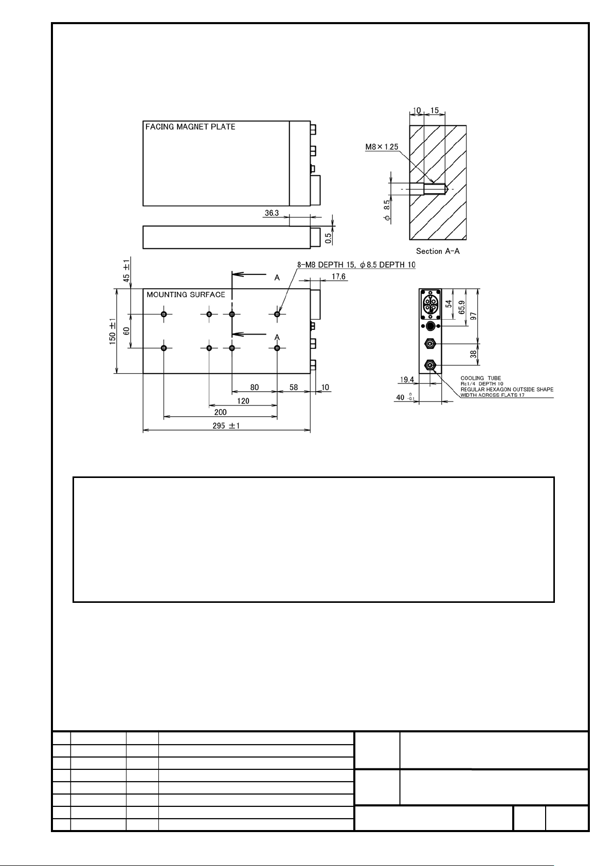
FANUC CORPORATION
Ed
Date
Design
Description
B-65382EN/05-06
Akasako
01
Newly designed
/87
Drawing
Akasako
02
Add M3 model, Correct
machine mounting holes.
LiS 3000M2/2HV-B (A06B-0462-B020#1002)
LiS 3000M2/2-B (A06B-0462-B120#1002)
NOTE
1 In this model, power lines are connected with connectors. Please prepare the connectors.
2 This drawing contains no magnetic pole sensor. To use an increm ental linear encoder, a magnetic pole
sensor is required.
3 The surface opposite to the magnet plate is not mac hi ned. If the surface is ground for adjustment of the
thickness or other purposes, the insulation perform ance may degrade.
4 The level 3 tolerance defined in JIS B 0613-76 is applied to the toler ance of the center distance between
No.
FANUC LINEAR MOTOR LiS-B series
S1, S2, M2, M3 Model
Page
44
Page 45
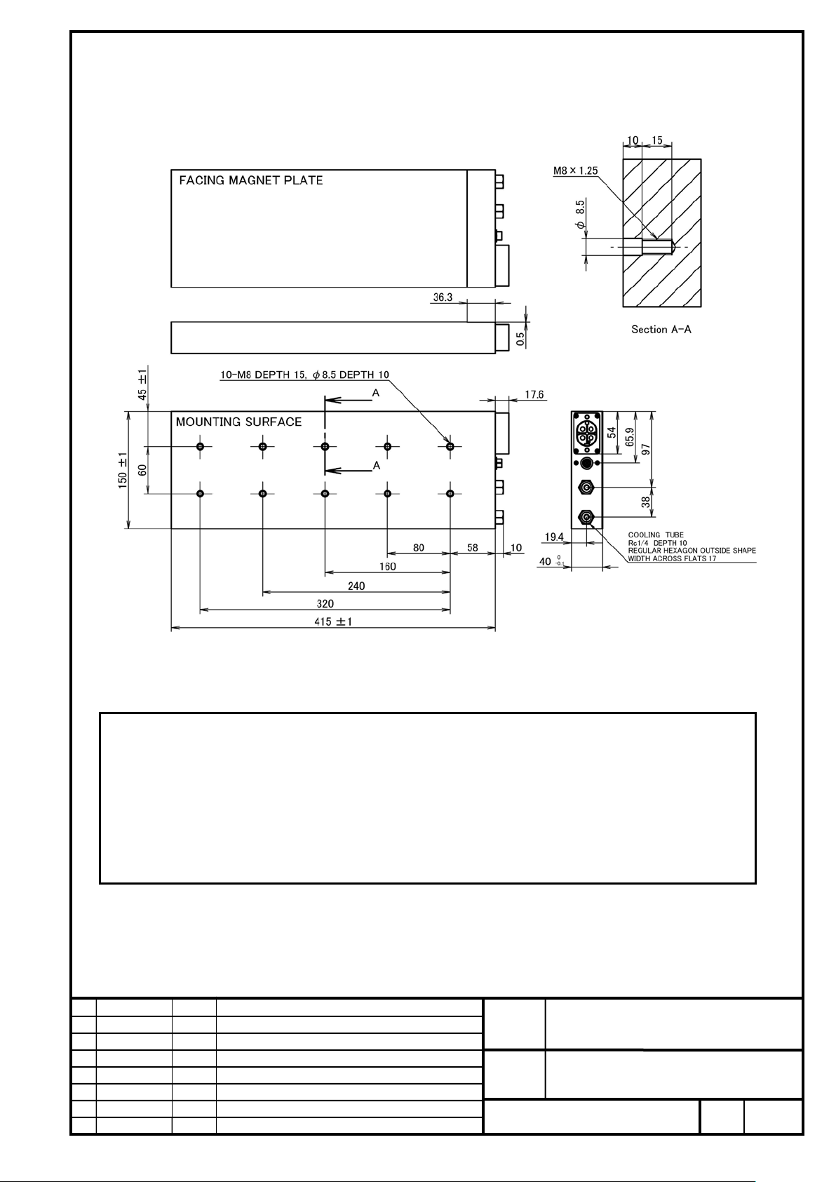
FANUC CORPORATION
Ed
Date
Design
Description
B-65382EN/05-06
Akasako
01
Newly designed
/87
Drawing
Akasako
02
Add M3 model, Correct
machine mounting holes.
LiS 4500M2/2HV-B (A06B-0463-B020#1002)
LiS 4500M2/2-B (A06B-0463-B120#1002)
NOTE
1 In this model, power lines are connected with connectors. Please prepare the connect ors.
2 This drawing contains no magnetic pole sensor. To use an incremental li near encoder, a magnetic pole
sensor is required.
3 The surface opposite to the magnet plate is not mac hi ned. If the surface is ground for adjustment of the
thickness or other purposes, the insulation perform ance may degrade.
4 The level 3 tolerance defined in JIS B 0613-76 is applied to the toler ance of the center distance between
FANUC LINEAR MOTOR LiS-B series
S1, S2, M2, M3 Model
No.
Page
45
Page 46

FANUC CORPORATION
Ed
Date
Design
Description
B-65382EN/05-06
Akasako
01
Newly designed
/87
Drawing
Akasako
02
Add M3 model, Correct
machine mounting holes.
LiS 6000M2/2HV-B (A06B-0464-B020#1002)
LiS 6000M2/2-B (A06B-0464-B120#1002)
NOTE
1 In this model, power lines are connected with connectors. Please prepare the connectors.
2 This drawing contains no magnetic pole sensor. To use an incremental li near encoder, a magnetic pole
sensor is required.
3 The surface opposite to the magnet plate is not mac hi ned. If the surface is ground for adjustment of the
thickness or other purposes, the insulation perform ance may degrade.
4 The level 3 tolerance defined in JIS B 0613-76 is applied to the tolerance of the center distance between
No.
FANUC LINEAR MOTOR LiS-B series
S1, S2, M2, M3 Model
Page
46
Page 47
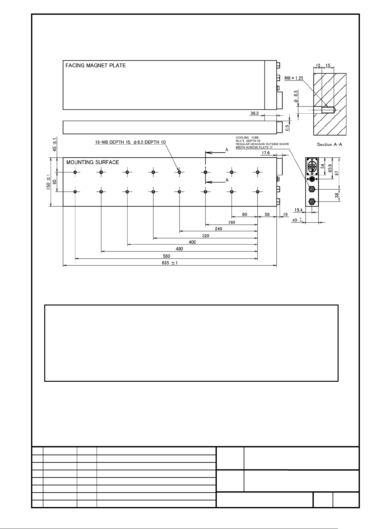
FANUC CORPORATION
Ed
Date
Design
Description
B-65382EN/05-06
Akasako
01
Newly designed
/87
Drawing
Akasako
02
Add M3 model, Correct
machine mounting holes.
LiS 7500M2/2HV-B (A06B-0465-B020#1002)
LiS 7500M2/2-B (A06B-0465-B120#1002)
NOTE
1 In this model, power lines are connected with connectors. Please prepare the connectors.
2 This drawing contains no magnetic pole sensor. To use an incremental li near encoder, a magnetic pole
sensor is required.
3 The surface opposite to the magnet plate is not mac hi ned. If the surface is ground for adjustment of the
thickness or other purposes, the insulation perform ance may degrade.
4 The level 3 tolerance defined in JIS B 0613-76 is applied to the toler ance of the center distance between
No.
FANUC LINEAR MOTOR LiS-B series
S1, S2, M2, M3 Model
Page
47
Page 48
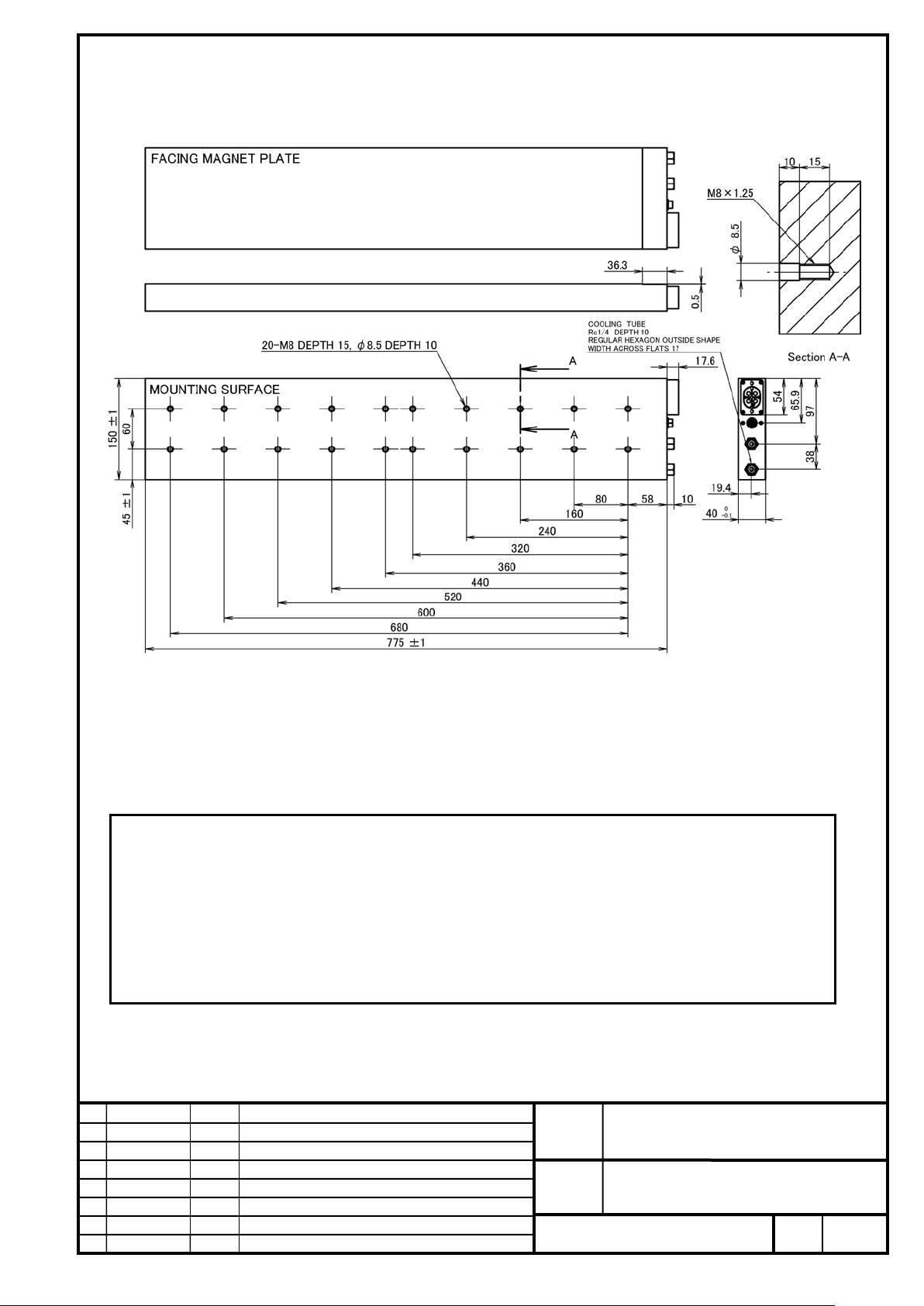
FANUC CORPORATION
Ed
Date
Design
Description
B-65382EN/05-06
Akasako
01
Newly designed
/87
Drawing
Akasako
02
Add M3 model, Correct
machine mounting holes.
LiS 9000M2/2HV-B (A06B-0466-B020#1002)
LiS 9000M2/2-B (A06B-0466-B120#1002)
NOTE
1 In this model, power lines are connected with connectors. Please prepare the connectors.
2 This drawing contains no magnetic pole sensor. To use an incremental li near encoder, a magnetic pole
sensor is required.
3 The surface opposite to the magnet plate is not m achined. If the surface is ground for adjustment of the
thickness or other purposes, the insulation perform ance may degrade.
4 The level 3 tolerance defined in JIS B 0613-76 is applied to the toler ance of the center distance between
No.
FANUC LINEAR MOTOR LiS-B series
S1, S2, M2, M3 Model
Page
48
Page 49
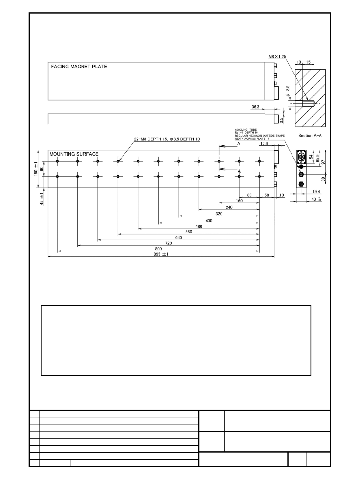
FANUC CORPORATION
Ed
Date
Design
Description
B-65382EN/05-06
Akasako
01
Newly designed
/87
Drawing
Akasako
02
Add M3 model, Correct
machine mounting holes.
LiS 11000M2/2HV-B (A06B-0467-B020#1002)
LiS 11000M2/2-B (A06B-0467-B120#1002)
NOTE
1 In this model, power lines are connected with connectors. Please prepare the connectors.
2 This drawing contains no magnetic pole sensor. To use an incremental li near encoder, a magnetic pole
sensor is required.
3 The surface opposite to the magnet plate is not mac hi ned. If the surface is ground for adjustment of the
thickness or other purposes, the insulation perform ance may degrade.
4 The level 3 tolerance defined in JIS B 0613-76 is applied to the toler ance of the center distance between
FANUC LINEAR MOTOR LiS-B series
S1, S2, M2, M3 Model
No.
Page
49
Page 50
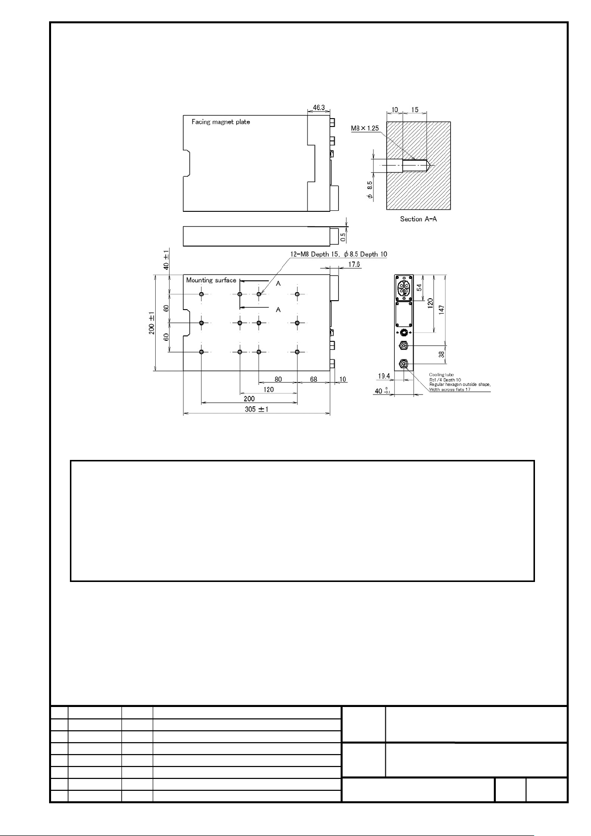
FANUC CORPORATION
Ed
Date
Design
Description
B-65382EN/05-06
Akasako
01
Newly designed
/87
Drawing
Akasako
02
Add M3 model, Correct
machine mounting holes.
LiS 4500M3/2HV-B (A06B-0468-B020#1002)
LiS 4500M3/2-B (A06B-0468-B120#1002)
NOTE
1 In this model, power lines are connected with connectors. Please prepare the connector s .
2 This drawing contains no magnetic pole sensor. To use an incremental li near encoder, a magnetic pole
sensor is required.
3 The surface opposite to the magnet plate is not mac hi ned. If the surface is ground for adjustment of the
thickness or other purposes, the insulation perform ance may degrade.
4 The level 3 tolerance defined in JIS B 0613-76 is applied to the toler ance of the center distance between
No.
FANUC LINEAR MOTOR LiS-B series
S1, S2, M2, M3 Model
Page
50
Page 51
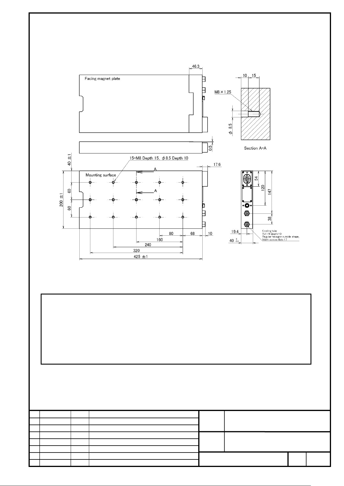
FANUC CORPORATION
Ed
Date
Design
Description
B-65382EN/05-06
Akasako
01
Newly designed
/87
Drawing
Akasako
02
Add M3 model, Correct
machine mounting holes.
LiS 7000M3/2HV-B (A06B-0469-B020#1002)
LiS 7000M3/2-B (A06B-0469-B120#1002)
LiS 7000M3/4-B (A06B-0469-B220#1002)
NOTE
1 In this model, power lines are connected with connectors. Please prepare the connectors.
2 This drawing contains no magnetic pole sensor. To use an incremental li near encoder, a magnetic pole
sensor is required.
3 The surface opposite to the magnet plate is not mac hi ned. If the surface is ground for adjustment of the
thickness or other purposes, the insulation perform ance may degrade.
4 The level 3 tolerance defined in JIS B 0613-76 is applied to the tol erance of the center distance between
FANUC LINEAR MOTOR LiS-B series
S1, S2, M2, M3 Model
No.
Page
51
Page 52
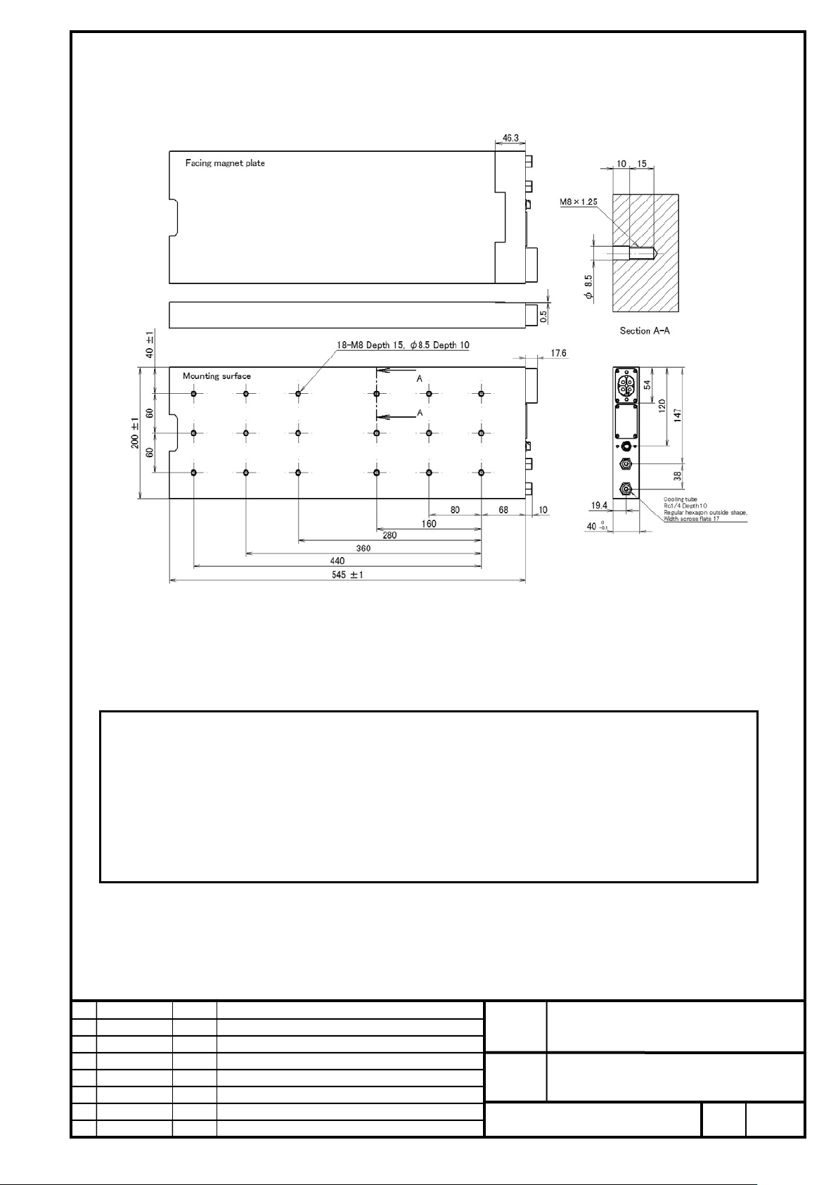
FANUC CORPORATION
Ed
Date
Design
Description
B-65382EN/05-06
Akasako
01
Newly designed
/87
Drawing
Akasako
02
Add M3 model, Correct
machine mounting holes.
LiS 9000M3/2HV-B (A06B-0470-B020#1002)
LiS 9000M3/2-B (A06B-0470-B120#1002)
NOTE
1 In this model, power lines are connected with connectors. Please prepare the connectors .
2 This drawing contains no magnetic pole sensor. To use an incremental li near encoder, a magnetic pole
sensor is required.
3 The surface opposite to the magnet plate is not mac hi ned. If the surface is ground for adjustment of the
thickness or other purposes, the insulation perform ance may degrade.
4 The level 3 tolerance defined in JIS B 0613-76 is applied to the toler ance of the center distance between
No.
FANUC LINEAR MOTOR LiS-B series
S1, S2, M2, M3 Model
Page
52
Page 53
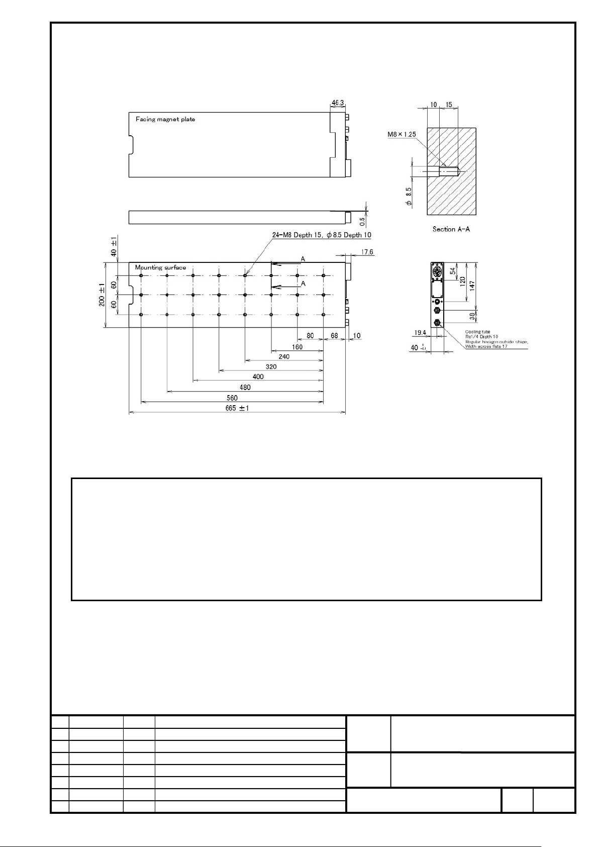
FANUC CORPORATION
Ed
Date
Design
Description
B-65382EN/05-06
Akasako
01
Newly designed
/87
Drawing
Akasako
02
Add M3 model, Correct
machine mounting holes.
LiS 11000M3/2HV-B (A06B-0471-B020#1002)
LiS 11000M3/2-B (A06B-0471-B120#1002)
NOTE
1 In this model, power lines are connected with connectors. Please prepare the connectors.
2 This drawing contains no magnetic pole sensor. To use an incremental li near encoder, a magnetic pole
sensor is required.
3 The surface opposite to the magnet plate is not mac hi ned. If the surface is ground for adjustment of the
thickness or other purposes, the insulation perform ance may degrade.
4 The level 3 tolerance defined in JIS B 0613-76 is applied to the toler ance of the center distance between
No.
FANUC LINEAR MOTOR LiS-B series
S1, S2, M2, M3 Model
Page
53
Page 54
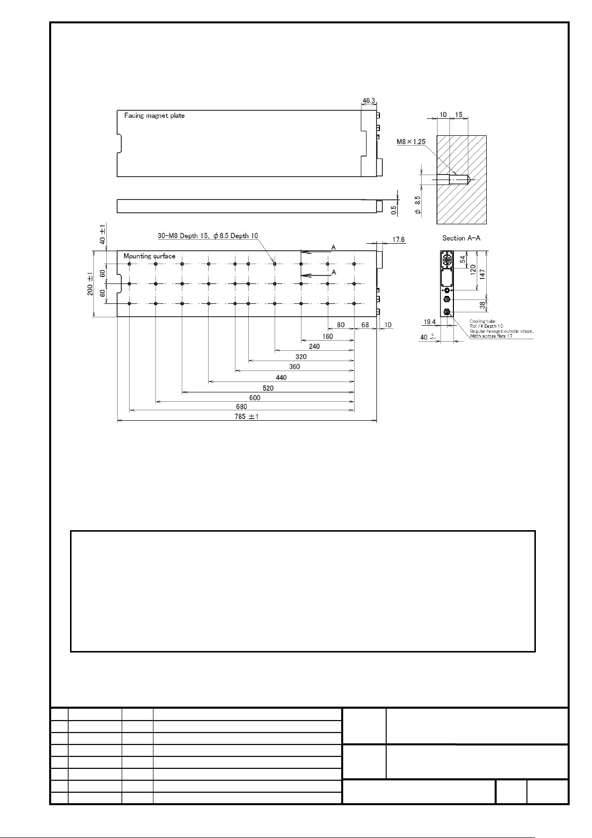
FANUC CORPORATION
Ed
Date
Design
Description
B-65382EN/05-06
Akasako
01
Newly designed
/87
Drawing
Akasako
02
Add M3 model, Correct
machine mounting holes.
LiS 14000M3/2HV-B (A06B-0472-B020#1002)
LiS 14000M3/2-B (A06B-0472-B120#1002)
NOTE
1 In this model, power lines are connected with connectors. Please prepare the connectors .
2 This drawing contains no magnetic pole sensor. To use an incremental li near encoder, a magnetic pole
sensor is required.
3 The surface opposite to the magnet plate is not mac hi ned. If the surface is ground for adjustment of the
thickness or other purposes, the insulation perform ance may degrade.
4 The level 3 tolerance defined in JIS B 0613-76 is applied to the toler ance of the center distance between
No.
FANUC LINEAR MOTOR LiS-B series
S1, S2, M2, M3 Model
Page
54
Page 55
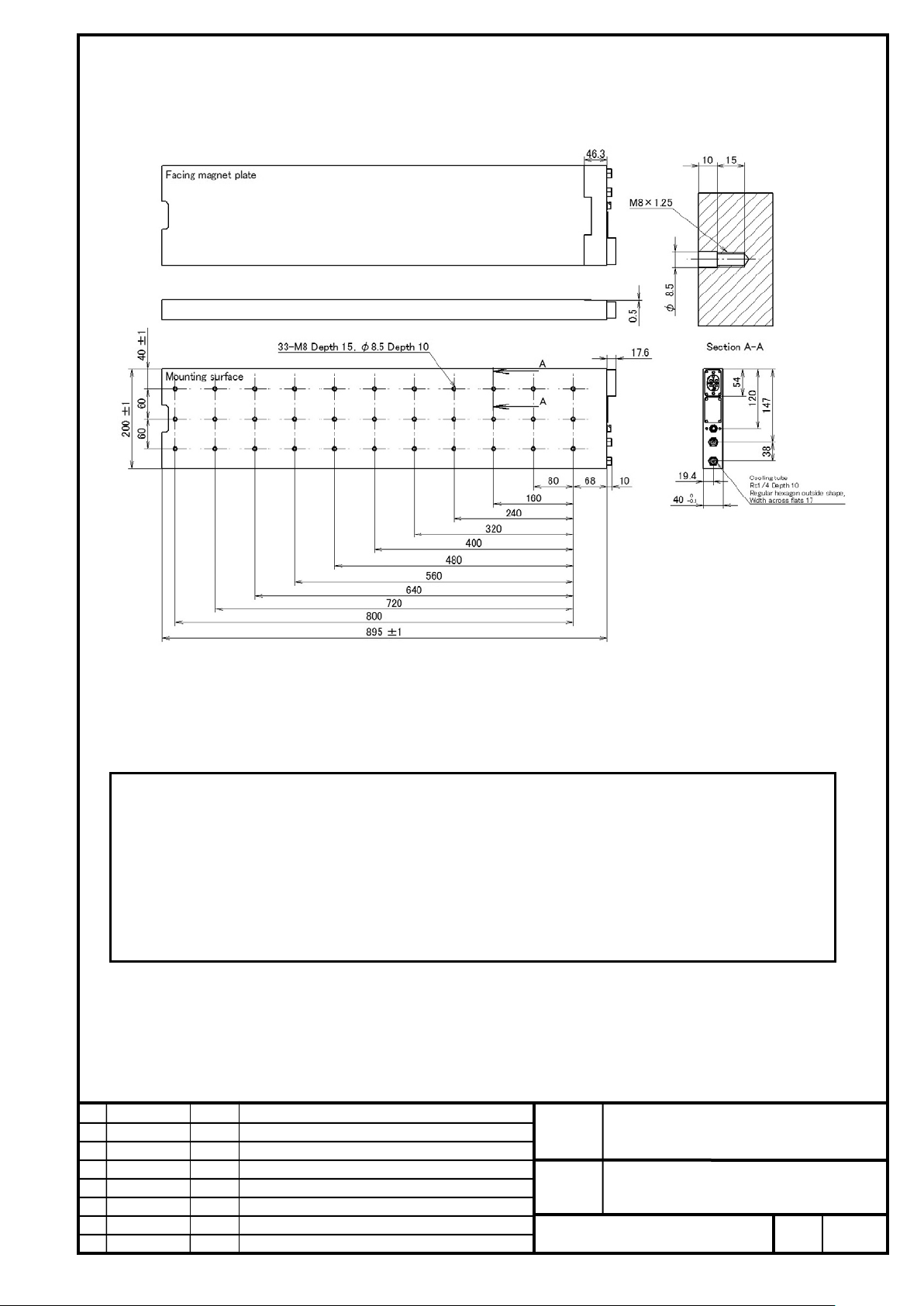
FANUC CORPORATION
Ed
Date
Design
Description
B-65382EN/05-06
Akasako
01
Newly designed
/87
Drawing
Akasako
02
Add M3 model, Correct
machine mounting holes.
LiS 16000M3/2HV-B (A06B-0473-B020#1002)
LiS 16000M3/2-B (A06B-0473-B120#1002)
NOTE
1 In this model, power lines are connected with connectors. Please prepare the connectors.
2 This drawing contains no magnetic pole sensor. To use an incremental li near encoder, a magnetic pole
sensor is required.
3 The surface opposite to the magnet plate is not machined. If the surface is ground for adjustment of the
thickness or other purposes, the insulation perform ance may degrade.
4 The level 3 tolerance defined in JIS B 0613-76 is applied to the toler ance of the center distance between
No.
FANUC LINEAR MOTOR LiS-B series
S1, S2, M2, M3 Model
Page
55
Page 56
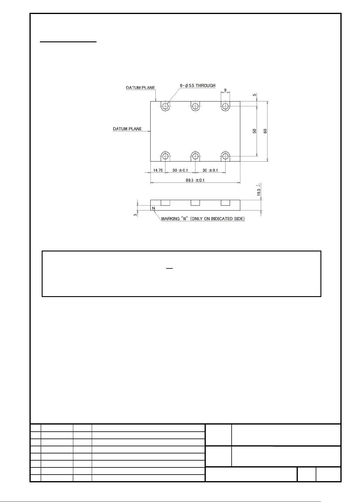
FANUC CORPORATION
Ed
Date
Design
Description
B-65382EN/05-06
Akasako
01
Newly designed
/87
Drawing
Akasako
02
Add M3 model, Correct
���
���
respect to the mounting hole closest to the referenc e plane i n the longitudinal direction.
7-2 Magnet Plate
Magnet plate S1 (For LiS
A06B-0440-B011#A090 (Length 90mm)
S1)
Mass : 0.3kg
NOTE
1 This magnet plate is dedicated to the LiS
magnet plates in combination according to the required axis lengt h ( track length).
2 For machine mounting holes, the tolerance should be set based on the dis tance to each mounting hole with
S1. This cannot be used for other models. Use two types of
No.
FANUC LINEAR MOTOR LiS-B series
S1, S2, M2, M3 Model
Page
56
Page 57
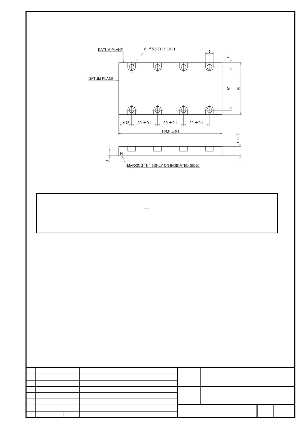
FANUC CORPORATION
Ed
Date
Design
Description
B-65382EN/05-06
Akasako
01
Newly designed
/87
Drawing
Akasako
02
Add M3 model, Correct
���
respect to the mounting hole closest to the reference plane in the longitudinal direction.
A06B-0440-B011#A120 (Length 120mm)
Mass : 0.4kg
NOTE
1 This magnet plate is dedicated to the LiS
magnet plates in combination according to the required axis length (t r ack length).
2 For machine mounting holes, the tolerance should be set based on the dis tance to each mounting hole with
S1. This cannot be used for other models. Use two types of
No.
FANUC LINEAR MOTOR LiS-B series
S1, S2, M2, M3 Model
Page
57
Page 58
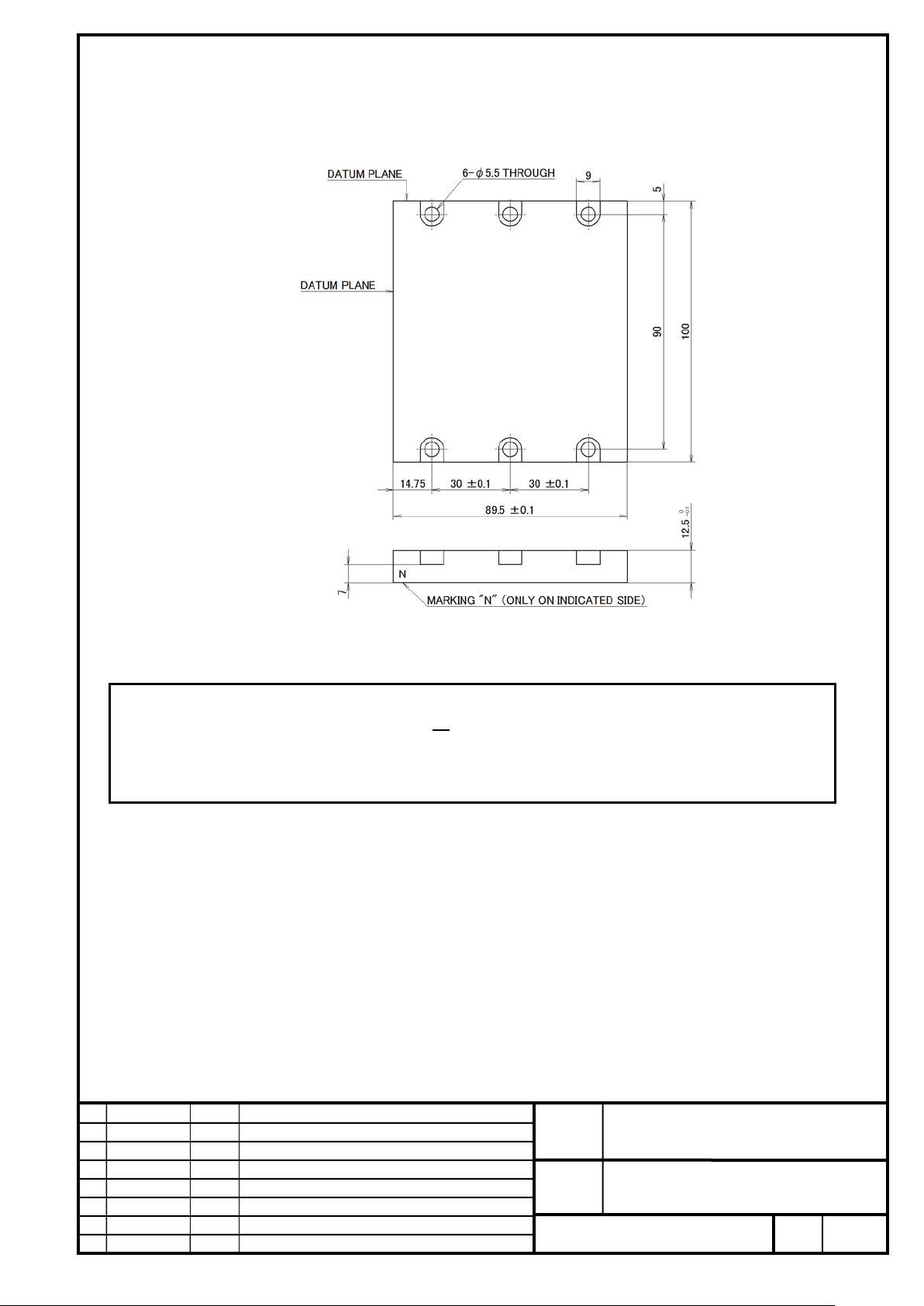
FANUC CORPORATION
Ed
Date
Design
Description
B-65382EN/05-06
Akasako
01
Newly designed
/87
Drawing
Akasako
02
Add M3 model, Correct
���
���
respect to the mounting hole closest to the referenc e plane i n the longitudinal direction.
Magnet plate S2 (For LiS
A06B-0440-B012#A090 (Length 90mm)
S2)
Mass : 0.8kg
NOTE
1 This magnet plate is dedicated to the LiS
magnet plates in combination according to the required axis length (t r ack length).
2 For machine mounting holes, the tolerance should be set based on the dis tance to each mounting hole with
S2. This cannot be used for other models. Use two types of
No.
FANUC LINEAR MOTOR LiS-B series
S1, S2, M2, M3 Model
Page
58
Page 59
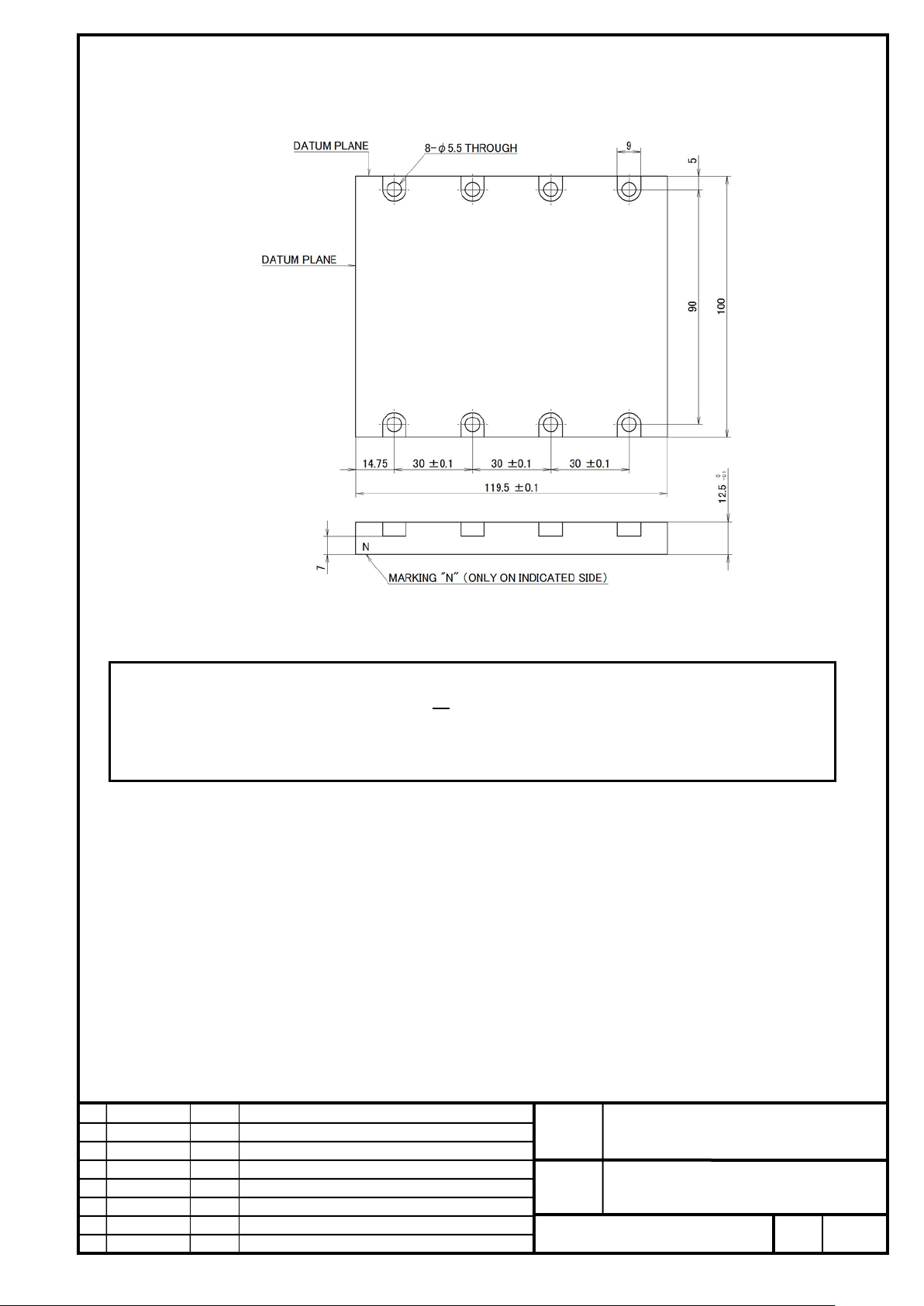
FANUC CORPORATION
Ed
Date
Design
Description
B-65382EN/05-06
Akasako
01
Newly designed
/87
Drawing
Akasako
02
Add M3 model, Correct
���
respect to the mounting hole closest to the reference plane in the longitudinal direction.
A06B-0440-B012#A120 (Length 120mm)
Mass : 1.0kg
NOTE
1 This magnet plate is dedicated to the LiS
magnet plates in combination according to the required axis length (t r ack length).
2 For machine mounting holes, the tolerance should be set based on the dis tance to each mounting hole with
S2. This cannot be used for other models. Use two types of
No.
FANUC LINEAR MOTOR LiS-B series
S1, S2, M2, M3 Model
Page
59
Page 60
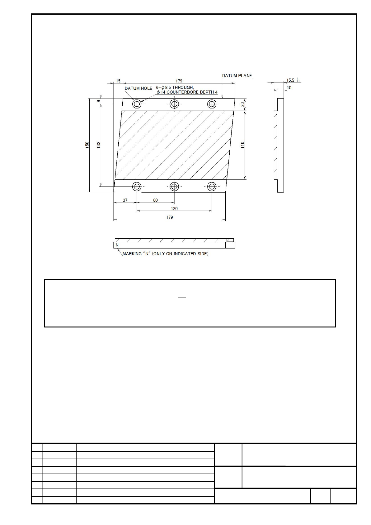
FANUC CORPORATION
Ed
Date
Design
Description
B-65382EN/05-06
Akasako
01
Newly designed
/87
Drawing
Akasako
02
Add M3 model, Correct
����
����
respect to the datum hole. The level 3 tolerance defined in JIS B 0613-76 should be applied.
Magnet plate M2 (For LiS
A06B-0440-B022#A180 (Length 180mm)
M2)
Mass : 2.7kg
NOTE
1 This magnet plate is dedicated to the LiS
magnet plates in combination according to the required axis length (t r ack length).
2 For machine mounting holes, the tolerance should be set based on the di s tance to each mounting hole with
M2. This cannot be used for other models. Use t wo types of
No.
FANUC LINEAR MOTOR LiS-B series
S1, S2, M2, M3 Model
Page
60
Page 61

FANUC CORPORATION
Ed
Date
Design
Description
B-65382EN/05-06
Akasako
01
Newly designed
/87
Drawing
Akasako
02
Add M3 model, Correct
����
respect to the datum hole. The level 3 tolerance defined in JIS B 0613-76 should be applied.
A06B-0440-B022#A240 (Length 240mm)
Mass : 3.6kg
NOTE
1 This magnet plate is dedicated to the LiS
four types of magnet plates in combination according to the required axis length (track length).
2 For machine mounting holes, the tolerance should be set based on the di s tance to each mounting hole with
M2. This cannot be used for other models. Use the above
No.
FANUC LINEAR MOTOR LiS-B series
S1, S2, M2, M3 Model
Page
61
Page 62
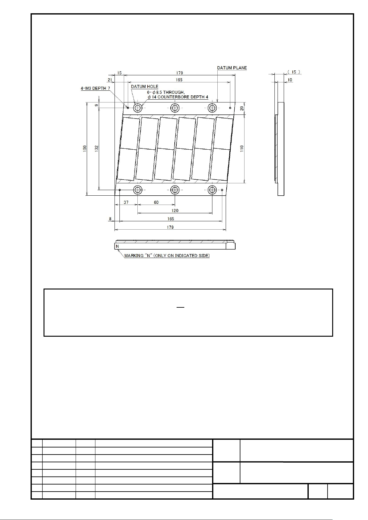
FANUC CORPORATION
Ed
Date
Design
Description
B-65382EN/05-06
Akasako
01
Newly designed
/87
Drawing
Akasako
02
Add M3 model, Correct
����
respect to the datum hole. The level 3 tolerance defined in JIS B 0613-76 should be applied.
A06B-0440-B022#E180 (Environmental resistance type: Length 180mm)
Mass: 2.7kg
NOTE
1 This magnet plate is dedicated to the LiS
four types of magnet plates in combination according to the required axis length (track length).
2 For machine mounting holes, the tolerance should be set based on the di s tance to each mounting hole with
M2. This cannot be used for other models. Use the above
No.
FANUC LINEAR MOTOR LiS-B series
S1, S2, M2, M3 Model
Page
62
Page 63
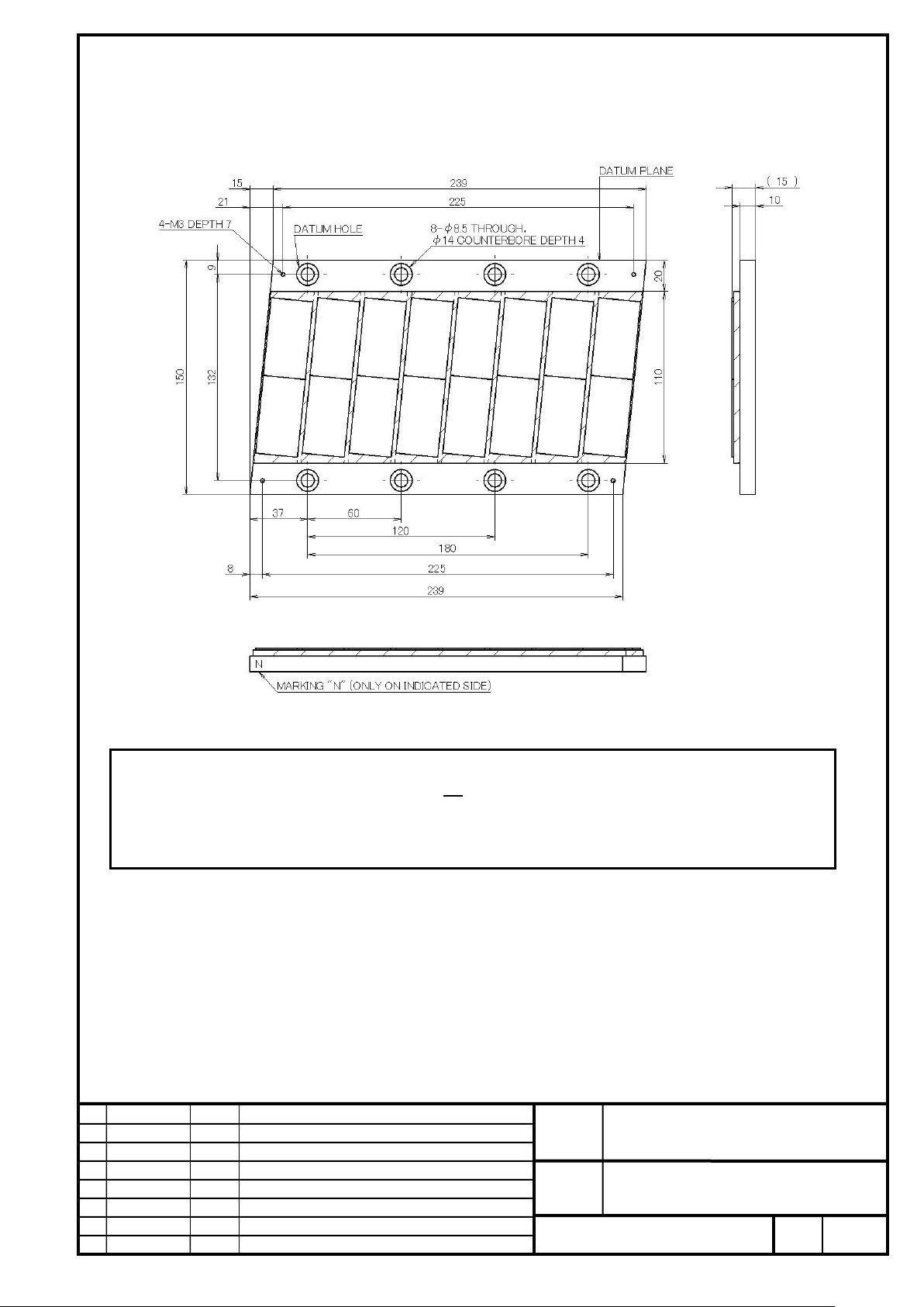
FANUC CORPORATION
Ed
Date
Design
Description
B-65382EN/05-06
Akasako
01
Newly designed
/87
Drawing
Akasako
02
Add M3 model, Correct
����
respect to the datum hole. The level 3 tolerance defined in JIS B 0613-76 should be applied.
A06B-0440-B022#E240 (Environmental resistance type: Length 240mm)
Mass: 3.6kg
NOTE
1 This magnet plate is dedicated to the LiS
four types of magnet plates in combination according to the required axis length (track length).
2 For machine mounting holes, the tolerance should be set based on the dis tance to each mounting hole with
M2. This cannot be used for other models. Use the above
FANUC LINEAR MOTOR LiS-B series
S1, S2, M2, M3 Model
No.
Page
63
Page 64

FANUC CORPORATION
Ed
Date
Design
Description
B-65382EN/05-06
Akasako
01
Newly designed
/87
Drawing
Akasako
02
Add M3 model, Correct
����
�����
respect to the datum hole. The level 3 tolerance defined in JIS B 0613-76 should be applied.
02
Magnet plate M3 (For LiS
A06B-0440-B023#A180 (Length 180mm)
M3)
Mass : 2.7kg
NOTE
1 This magnet plate is dedicated to the LiS
of magnet plates in combination according to the required axis length ( track length).
2 For machine mounting holes, the tolerance should be set based on the dis tance to each mounting hole with
M3. This cannot be used for other models. Use t wo types
No.
FANUC LINEAR MOTOR LiS-B series
S1, S2, M2, M3 Model
Page
64
Page 65
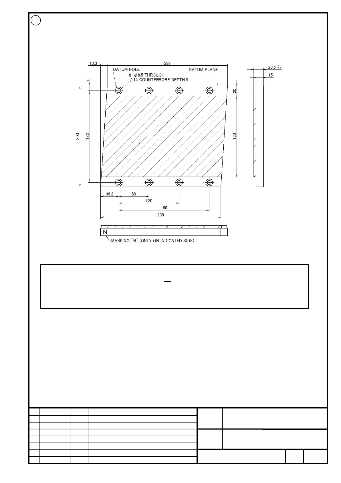
FANUC CORPORATION
Ed
Date
Design
Description
B-65382EN/05-06
Akasako
01
Newly designed
/87
Drawing
Akasako
02
Add M3 model, Correct
����
respect to the datum hole. The level 3 tolerance d efined in JIS B 0613-76 should be applied.
02
A06B-0440-B023#A240 (Length 240mm)
Mass : 3.6kg
NOTE
1 This magnet plate is dedicated to the LiS
four types of magnet plates in combination according to the required axis length (track length).
2 For machine mounting holes, the tolerance should be set based on the dis tance to each mounting hole with
M3. This cannot be used for other models. Use the above
No.
FANUC LINEAR MOTOR LiS-B series
S1, S2, M2, M3 Model
Page
65
Page 66
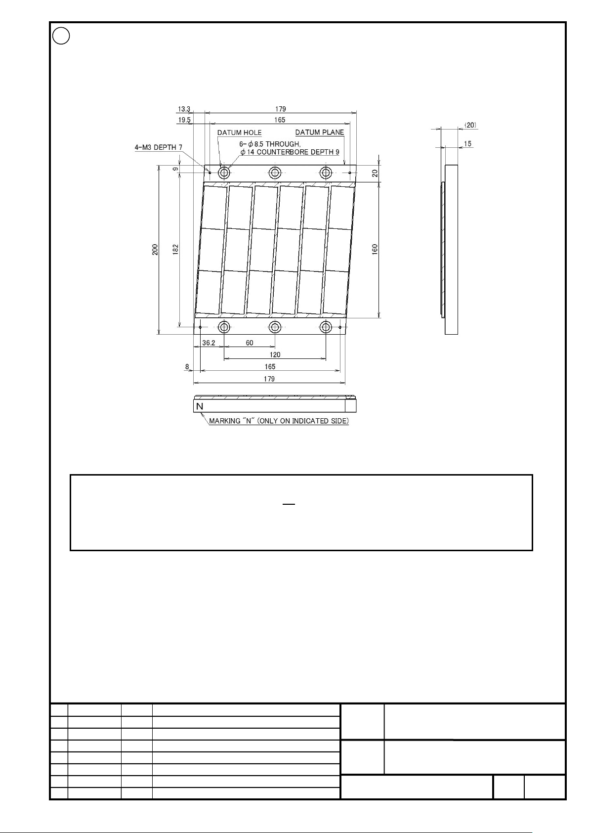
FANUC CORPORATION
Ed
Date
Design
Description
B-65382EN/05-06
Akasako
01
Newly designed
/87
Drawing
Akasako
02
Add M3 model, Correct
����
respect to the datum hole. The level 3 tolerance defined in JIS B 0613-76 should be applied.
02
A06B-0440-B023#E180 (Environmental resistance type: Length 180mm)
Mass: 2.7kg
NOTE
1 This magnet plate is dedicated to the LiS
four types of magnet plates in combination according to the required axis length (track length).
2 For machine mounting holes, the tolerance should be set based on the dis tance to each mounting hole with
M3. This cannot be used for other models. Use the above
No.
FANUC LINEAR MOTOR LiS-B series
S1, S2, M2, M3 Model
Page
66
Page 67
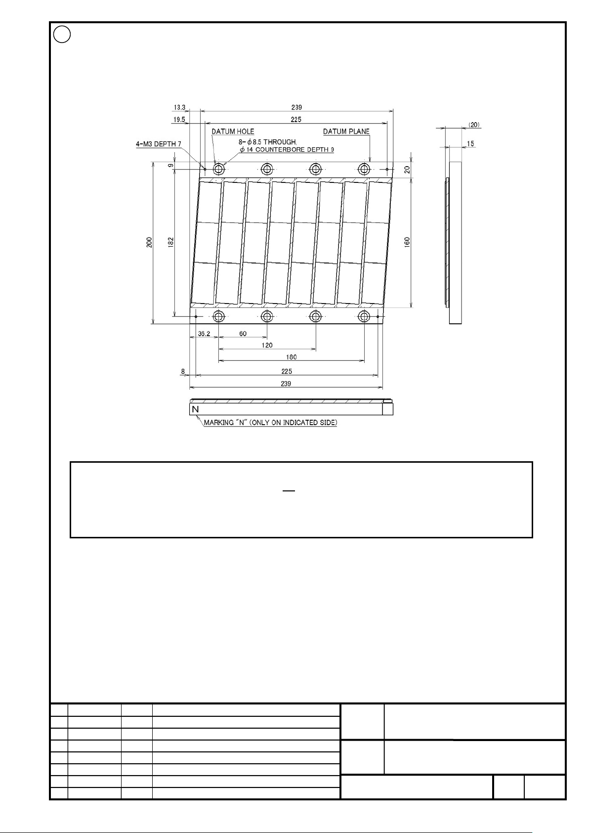
FANUC CORPORATION
Ed
Date
Design
Description
B-65382EN/05-06
Akasako
01
Newly designed
/87
Drawing
Akasako
02
Add M3 model, Correct
����
respect to the datum hole. The level 3 tolerance defined in J IS B 0613-76 should be applied.
02
A06B-0440-B023#E240 (Environmental resistance type: Length 240mm)
Mass: 3.6kg
NOTE
1 This magnet plate is dedicated to the LiS
four types of magnet plates in combination according to the required axis length (track length).
2 For machine mounting holes, the tolerance should be set based on the dis tance to each mounting hole with
M3. This cannot be used for other models. Use the above
No.
FANUC LINEAR MOTOR LiS-B series
S1, S2, M2, M3 Model
Page
67
Page 68
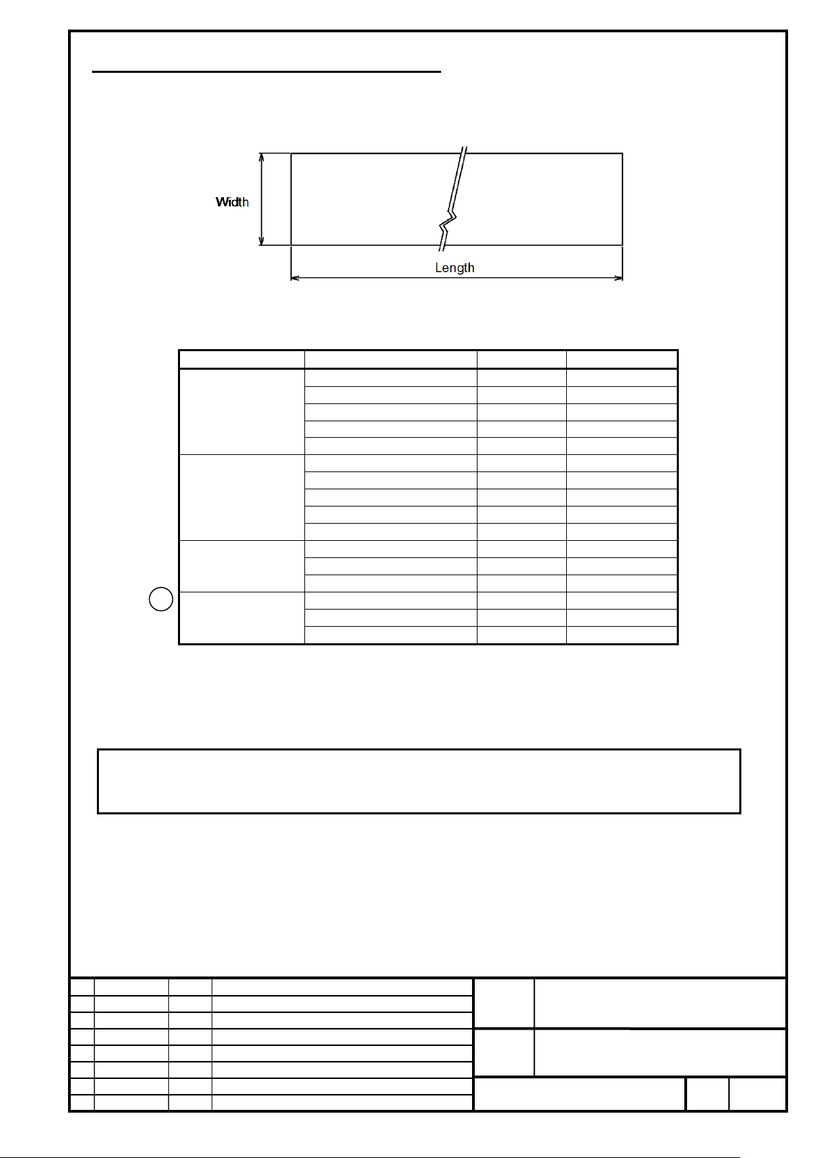
FANUC CORPORATION
Ed
Date
Design
Description
B-65382EN/05-06
Akasako
01
Newly designed
/87
Drawing
Akasako
02
Add M3 model, Correct
Magnet plate type
Specification number
Width (mm)
Length (mm)
A06B-0440-K770#100
50
1000
A06B-0440-K770#150
50
1500
A06B-0440-K770#200
50
2000
A06B-0440-K770#250
50
2500
A06B-0440-K770#300
50
3000
A06B-0440-K780#100
100
1000
A06B-0440-K780#150
100
1500
A06B-0440-K780#200
100
2000
A06B-0440-K780#250
100
2500
A06B-0440-K780#300
100
3000
A06B-0440-K760#200
110
2000
A06B-0440-K760#250
110
2500
A06B-0440-K760#300
110
3000
A06B-0440-K790#200
160
2000
A06B-0440-K790#250
160
2500
A06B-0440-K790#300
160
3000
manage the air gap since the thickness of the entire magnet plate increases.
7-3 Magnet Plate Protection Sheet (Optional)
You can order one of magnet plate protection sheets with different lengths according to the type of a magnet plate. You
can freely cut and tailor the plain sheet provided by us to the desired size for attaching it to the machine.
Material: SUS304 (with weak magnetism)
Thickness: 0.3 mm
S1
S2
M2
02
M3
The character in the specification number indi c ates the number of sheets.
0: One sheet
A: Ten sheets
* Either "0" or "A" can be selected.
NOTE
When this option is applied to the standard type magnet plate without a protection cover, use caution to
No.
FANUC LINEAR MOTOR LiS-B series
S1, S2, M2, M3 Model
Page
68
Page 69
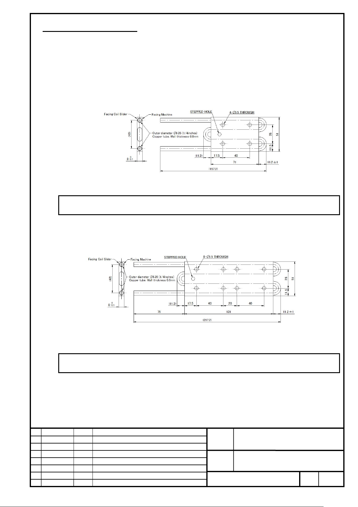
FANUC CORPORATION
Ed
Date
Design
Description
B-65382EN/05-06
Akasako
01
Newly designed
/87
Drawing
Akasako
02
Add M3 model, Correct
This cooling plate is dedicated to the LiS 300S1/4-B and LiS 300A1/4. It cannot be used for other models.
This cooling plate is dedicated to the LiS 600S1/4-B and LiS 600A1/4. It cannot be used for other models.
7-4 Cooling Plate (Optional)
For watar cooling of S1, S2 model , an optional cooling plate is required.
A stepped hole is located on the side of mounting surface to machine. (See stepped hole at figure)
By applying this surface to the mounting surface of machine, the desired cool ing capacity is obtained.
To mount the magnetic pole sensor,please prepare the spacers. For details, see Subsection 11-1.
For LiS 300S1/4-B (A06B-0443-K001#01A1)
Mass : 0.15kg
NOTE
For LiS 600S1/4-B (A06B-0443-K001#02A1)
Mass : 0.2kg
NOTE
FANUC LINEAR MOTOR LiS-B series
No.
S1, S2, M2, M3 Model
Page
69
Page 70
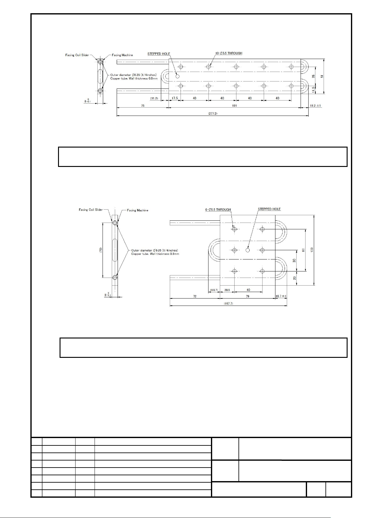
FANUC CORPORATION
Ed
Date
Design
Description
B-65382EN/05-06
Akasako
01
Newly designed
/87
Drawing
Akasako
02
Add M3 model, Correct
This cooling plate is dedicated to the LiS 900S1/4-B and LiS 900A1/4. It cannot be used for other models.
This cooling plate is dedicated to the LiS 600S2/3-B. I t cannot be used for other models.
For LiS 900S1/4-B (A06B-0443-K001#03A1)
Mass : 0.25kg
NOTE
For LiS 600S2/3-B (A06B-0443-K001#01S2)
Mass : 0.21kg
NOTE
FANUC LINEAR MOTOR LiS-B series
S1, S2, M2, M3 Model
No.
Page
70
Page 71
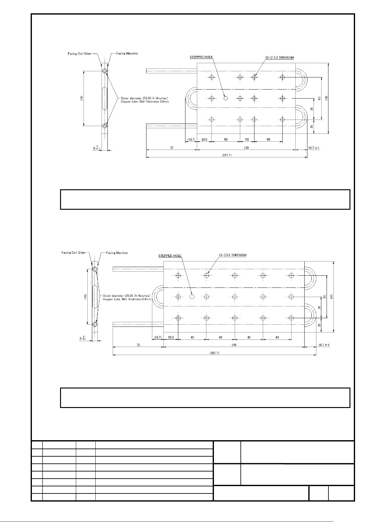
FANUC CORPORATION
Ed
Date
Design
Description
B-65382EN/05-06
Akasako
01
Newly designed
/87
Drawing
Akasako
02
Add M3 model, Correct
This cooling plate is dedicated to the LiS 1200S2/3-B. It cannot be used for other models.
This cooling plate is dedicated to the LiS 1800S2/3-B. It cannot be used for other models.
For LiS 1200S2/3-B (A06B-0443-K001#02S2)
Mass : 0.35kg
NOTE
For LiS 1800S2/3-B (A06B-0443-K001#03S2)
Mass : 0.48kg
NOTE
No.
FANUC LINEAR MOTOR LiS-B series
S1, S2, M2, M3 Model
Page
71
Page 72
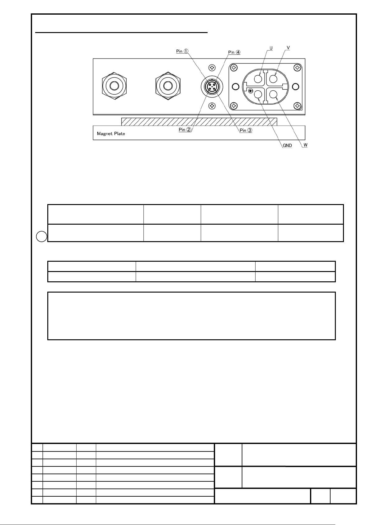
FANUC CORPORATION
Ed
Date
Design
Description
B-65382EN/05-06
Akasako
01
Newly designed
/87
Drawing
Akasako
02
Add M3 model, Correct
area (mm2)
AWG
Nominal cross-sectional area (mm2)
Cable diameter
≤ UL1015 AWG#21
≤ 0.5
φ6.0±0.4
movable type, connect it to a movable type on a terminal board.
8. Power Line and Thermal Connector Allocation
Pin allocation of power line and thermal connector is as follows.
Thermal connector
For PTC thermistor : Pins 1 and 2 (No polarity)
For NTC thermistor : Pins 3 and 4 (No polarity)
Cables usable for power lines
Linear motor model AWG
M2 model
M3 model
02
Cables usable for thermistor
NOTE
1 If the diameter of each wire does not comply with the above table, no connector waterproof is guaranteed.
Be sure to select conforming wires.
2 If the coil slider is a movable type, use a movable cable. If a cable c onnected to the connector is not a
UL1015 AWG#10
Nominal cross-sectional
5.5 or 6.0 φ4.69±0.12
Cable diameter
NOTE
NOTE
No.
FANUC LINEAR MOTOR LiS-B series
S1, S2, M2, M3 Model
Page
72
Page 73

FANUC CORPORATION
Ed
Date
Design
Description
B-65382EN/05-06
Akasako
01
Newly designed
/87
Drawing
Akasako
02
Add M3 model, Correct
(PS) capacity required for it.
No cooling (N)
No cooling (kW)
Water cooling (N)
Water cooling (kW)
LiS 300S1/4-B
60
0.06 x V + 0.02
120
0.12 x V + 0.08
LiS 600S1/4-B
100
0.1 x V + 0.03
240
0.24 x V + 0.16
LiS 900S1/4-B
140
0.14 x V + 0.03
360
0.36 x V + 0.24
LiS 600S2/3-B
100
0.1 x V + 0.02
240
0.24 x V + 0.13
LiS 1200S2/3-B
180
0.18 x V + 0.03
480
0.48 x V + 0.26
LiS 1800S2/3-B
260
0.26 x V + 0.04
720
0.72 x V + 0.39
LiS 3000M2/2HV-B
480
0.48 x V + 0.06
1200
1.2 x V + 0.39
LiS 3000M2/2-B
480
0.48 x V + 0.06
1200
1.2 x V + 0.40
LiS 4500M2/2HV-B
720
0.72 x V + 0.09
1800
1.8 x V + 0.58
LiS 4500M2/2-B
720
0.72 x V + 0.10
1800
1.8 x V + 0.59
LiS 6000M2/2HV-B
960
0.96 x V + 0.12
2400
2.4 x V + 0.78
LiS 6000M2/2-B
960
0.96 x V + 0.13
2400
2.4 x V + 0.79
LiS 7500M2/2HV-B
1200
1.2 x V + 0.15
3000
3.0 x V + 0.97
LiS 7500M2/2-B
1200
1.2 x V + 0.16
3000
3.0 x V + 0.99
LiS 9000M2/2HV-B
1440
1.44 x V + 0.19
3600
3.6 x V + 1.17
LiS 9000M2/2-B
1440
1.44 x V + 0.19
3600
3.6 x V + 1.19
LiS 11000M2/2HV-B
1680
1.68 x V + 0.22
4200
4.2 x V + 1.36
LiS 11000M2/2-B
1680
1.68 x V + 0.22
4200
4.2 x V + 1.40
LiS 4500M3/2HV-B
720
0.72 x V + 0.10
1800
1.8 x V + 0.61
LiS 4500M3/2-B
720
0.72 x V + 0.10
1800
1.8 x V + 0.60
LiS 7000M3/2HV-B
1080
1.08 x V + 0.15
2700
2.7 x V + 0.89
LiS 7000M3/2-B
1080
1.08 x V + 0.14
2700
2.7 x V + 0.89
LiS 7000M3/4-B
1080
1.08 x V + 0.14
2700
2.7 x V + 0.91
LiS 9000M3/2HV-B
1440
1.44 x V + 0.19
3600
3.6 x V + 1.20
LiS 9000M3/2-B
1440
1.44 x V + 0.19
3600
3.6 x V + 1.20
LiS 11000M3/2HV-B
1800
1.8 x V + 0.24
4500
4.5 x V + 1.50
LiS 11000M3/2-B
1800
1.8 x V + 0.24
4500
4.5 x V + 1.50
LiS 14000M3/2HV-B
2160
2.16 x V + 0.25
5400
5.4 x V + 1.69
LiS 14000M3/2-B
2160
2.16 x V + 0.35
5400
5.4 x V + 1.69
LiS 16000M3/2HV-B
2520
2.52 x V + 0.32
6300
6.3 x V + 2.09
LiS 16000M3/2-B
2520
2.52 x V + 0.31
6300
6.3 x V + 2.06
9. Output for Selecting Common Power Supply (PS)
Select a Common Power Supply (PS) required for driving the linear motor as follows.
NOTE
Common Power Supply (PS) selection described in this subsection assumes the use of l inear motors only
along one axis. When there is another feed axis or a spindle, consider and add the Comm on P ower Supply
Continuous output for Common Power Supply (PS) selection
02
Model name
Rated force
Output
Rated force
Output
V = Maximum speed to be used (m/s)
No.
FANUC LINEAR MOTOR LiS-B series
S1, S2, M2, M3 Model
Page
73
Page 74
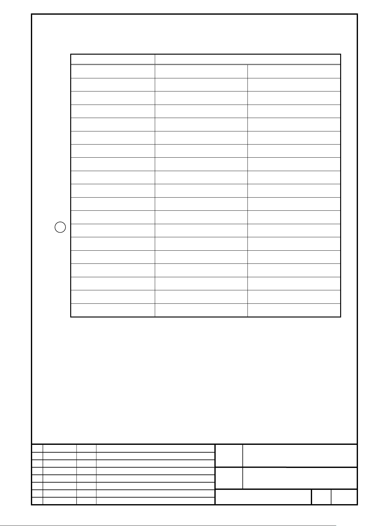
FANUC CORPORATION
Ed
Date
Design
Description
B-65382EN/05-06
Akasako
01
Newly designed
/87
Drawing
Akasako
02
Add M3 model, Correct
Model name
Output value for Common Power Supply (PS) selection (kW)
0 – 2m/s
0.3×V + 1.1
2– 4m/s
1.9
0 – 2m/s
0.6×V + 2.3
2– 4m/s
3.9
0 – 2m/s
0.9×V + 3.4
2– 4m/s
5.8
0 – 1m/s
0.6×V + 1.8
1– 3m/s
2.7
0 – 1m/s
1.2×V + 3.7
1– 3m/s
5.4
0 – 1m/s
1.8×V + 5.5
1– 3m/s
8.0
0 – 1m/s
3.0×V + 5.0
1– 2m/s
8.0
0 – 1m/s
4.5×V + 7.4
1– 2m/s
11.9
0 – 1m/s
6.0×V + 9.9
1– 2m/s
15.9
0 – 1m/s
7.5×V + 12.4
1– 2m/s
19.9
0 – 1m/s
9.0×V + 14.8
1– 2m/s
23.8
0 – 1m/s
10.5×V + 17.4
1– 2m/s
27.9
0 – 1m/s
4.5×V + 6.6
1– 2m/s
11.4
0 – 1m/s
6.75×V + 9.8
1– 2m/s
17.0
0 – 2m/s
6.75×V + 10.0
2– 4m/s
24.4
0 – 1m/s
9.0×V + 13.2
1– 2m/s
22.8
0 – 1m/s
11.25×V + 15.4
1– 2m/s
27.4
0 – 1m/s
13.5×V + 19.6
1– 2m/s
34.0
0 – 1m/s
15.75×V + 22.6
1– 2m/s
39.4
Maximum output during acceleration for Common Power Supply (PS) selection (200 V driving)
LiS 300S1/4-B
LiS 600S1/4-B
LiS 900S1/4-B
LiS 600S2/3-B
LiS 1200S2/3-B
LiS 1800S2/3-B
LiS 3000M2/2-B
LiS 4500M2/2-B
LiS 6000M2/2-B
LiS 7500M2/2-B
LiS 9000M2/2-B
LiS 11000M2/2-B
02
LiS 4500M3/2-B
LiS 7000M3/2-B
LiS 7000M3/4-B
LiS 9000M3/2-B
LiS 11000M3/2-B
LiS 14000M3/2-B
LiS 16000M3/2-B
V = Maximum speed to be used (m/s)
No.
FANUC LINEAR MOTOR LiS-B series
S1, S2, M2, M3 Model
Page
74
Page 75
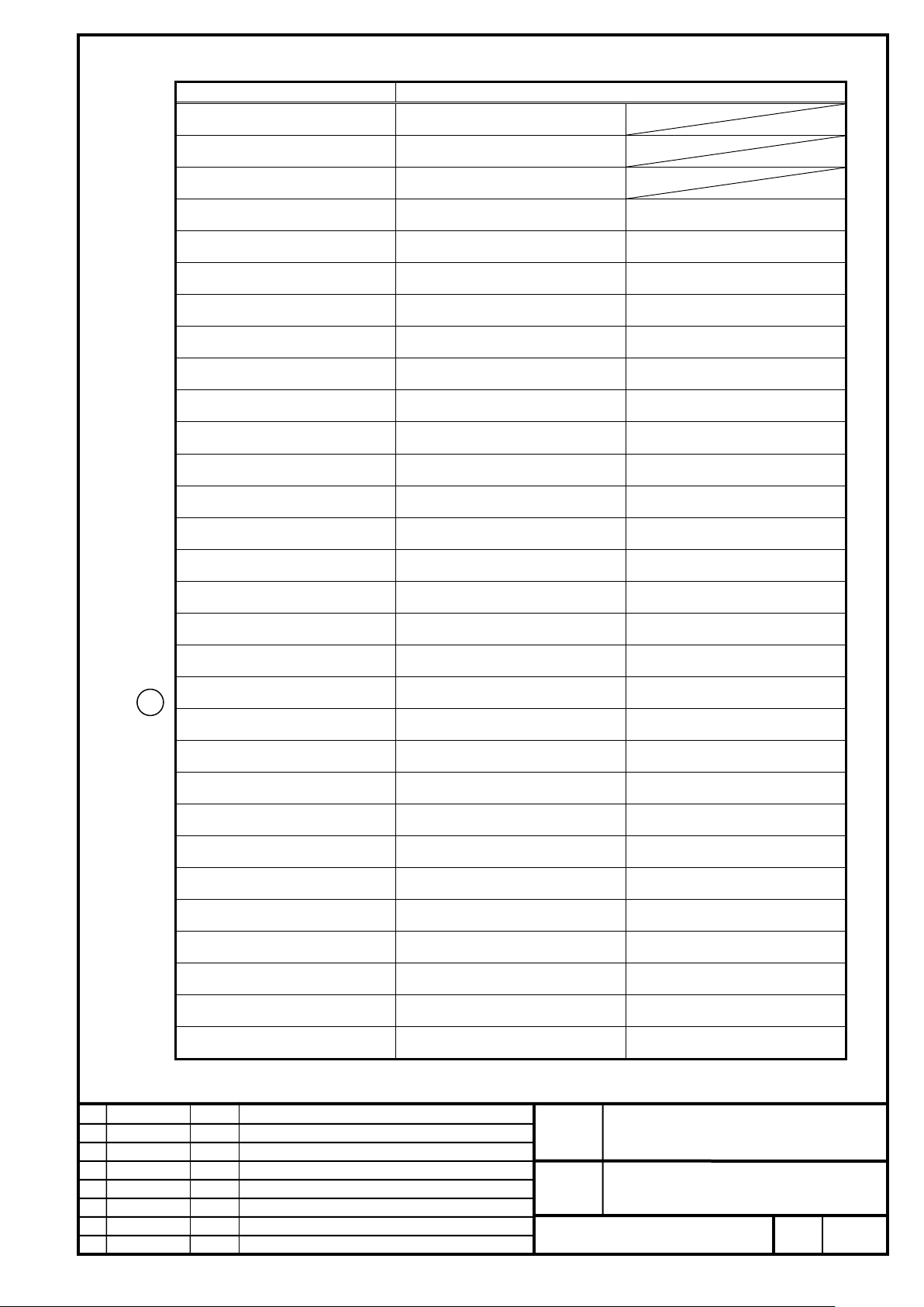
FANUC CORPORATION
Ed
Date
Design
Description
B-65382EN/05-06
Akasako
01
Newly designed
/87
Drawing
Akasako
02
Add M3 model, Correct
Model name
Output value for Common Power Supply (PS) selection (kW)
0 – 4m/s
0.3×V + 1.1
0 – 4m/s
0.6×V + 2.3
0 – 4m/s
0.9×V + 3.4
0 – 2m/s
0.6×V + 1.8
2– 3m/s
3.1
0 – 2m/s
1.2×V + 3.7
2– 3m/s
6.2
0 – 2m/s
1.8×V + 5.5
2– 3m/s
9.3
0 – 1m/s
3.0×V + 4.8
1– 2m/s
7.8
0 – 2m/s
3.0×V + 5.0
2 – 4m/s
11.0
0 – 1m/s
4.5×V + 7.2
1– 2m/s
11.7
0 – 2m/s
4.5×V + 7.4
2 – 4m/s
16.4
0 – 1m/s
6.0×V + 9.6
1– 2m/s
15.6
0 – 2m/s
6.0×V + 9.9
2 – 4m/s
21.9
0 – 1m/s
7.5×V + 12.0
1– 2m/s
19.5
0 – 2m/s
7.5×V + 12.4
2 – 4m/s
27.4
0 – 1m/s
9.0×V + 14.4
1– 2m/s
23.4
0 – 2m/s
9.0×V + 14.8
2 – 4m/s
32.8
0 – 1m/s
10.5×V + 16.8
1– 2m/s
27.3
0 – 2m/s
10.5×V + 17.4
2 – 4m/s
38.4
0 – 1m/s
4.5×V + 6.6
1– 2m/s
11.4
0 – 2m/s
4.5×V + 6.6
2 – 4m/s
16.2
0 – 1m/s
6.75×V + 9.9
1– 2m/s
17.1
0 – 2m/s
6.75×V + 9.8
2 – 4m/s
24.2
0 – 1m/s
9.0×V + 13.2
1– 2m/s
22.8
0 – 2m/s
9.0×V + 13.2
2 – 4m/s
32.4
0 – 1m/s
11.25×V + 15.8
1– 2m/s
27.8
0 – 2m/s
11.25×V + 16.5
2 – 4m/s
40.5
0 – 1m/s
13.5×V + 19.8
1– 2m/s
34.2
0 – 2m/s
13.5×V + 19.6
2 – 4m/s
48.4
0 – 1m/s
15.75×V + 23.0
1– 2m/s
39.8
0 – 2m/s
15.75×V + 22.6
2 – 4m/s
56.2
Maximum output during acceleration for Common Power Supply (PS) selection (400 V driving)
LiS 300S1/4-B
LiS 600S1/4-B
LiS 900S1/4-B
LiS 600S2/3-B
LiS 1200S2/3-B
LiS 1800S2/3-B
LiS 3000M2/2HV-B
LiS 3000M2/2-B
LiS 4500M2/2HV-B
LiS 4500M2/2-B
LiS 6000M2/2HV-B
LiS 6000M2/2-B
02
LiS 7500M2/2HV-B
LiS 7500M2/2-B
LiS 9000M2/2HV-B
LiS 9000M2/2-B
LiS 11000M2/2HV-B
LiS 11000M2/2-B
LiS 4500M3/2HV-B
LiS 4500M3/2-B
LiS 7000M3/2HV-B
LiS 7000M3/2-B
LiS 9000M3/2HV-B
LiS 9000M3/2-B
LiS 11000M3/2HV-B
LiS 11000M3/2-B
LiS 14000M3/2HV-B
LiS 14000M3/2-B
LiS 16000M3/2HV-B
LiS 16000M3/2-B
V = Maximum speed to be used (m/s)
No.
FANUC LINEAR MOTOR LiS-B series
S1, S2, M2, M3 Model
Page
75
Page 76

FANUC CORPORATION
Ed
Date
Design
Description
B-65382EN/05-06
Akasako
01
Newly designed
/87
Drawing
Akasako
02
Add M3 model, Correct
Model name
LS × WS for coil slider
LA × WA for active force area
LiS 300S1/4-B
79.3 × 60
74.6 × 40
LiS 600S1/4-B
139.3 × 60
134.6 × 40
LiS 900S1/4-B
199.3 × 60
194.6 × 40
LiS 600S2/3-B
79.3 × 100
74.6 × 80
LiS1200S2/3-B
139.3 × 100
134.6 × 80
LiS1800S2/3-B
199.3 × 100
194.6 × 80
Model name
LS × WS for coil slider
LA × WA for active force area
LiS 3000M2/2HV-B
295 × 150
258 × 100
LiS 3000M2/2-B
295 × 150
258 × 100
LiS 4500M2/2HV-B
415 × 150
378 × 100
LiS 4500M2/2-B
415 × 150
378 × 100
LiS 6000M2/2HV-B
535 × 150
498 × 100
LiS 6000M2/2-B
535 × 150
498 × 100
LiS 7500M2/2HV-B
655 × 150
618 × 100
LiS 7500M2/2-B
655 × 150
618 × 100
LiS 9000M2/2HV-B
775 × 150
738 × 100
LiS 9000M2/2-B
775 × 150
738 × 100
LiS 11000M2/2HV-B
895 × 150
858 × 100
LiS 11000M2/2-B
895 × 150
858 × 100
10. ACTIVE FORCE AREA OF THE LINEAR MOTOR
S1, S2 model
M2 model
No.
FANUC LINEAR MOTOR LiS-B series
S1, S2, M2, M3 Model
Page
76
Page 77
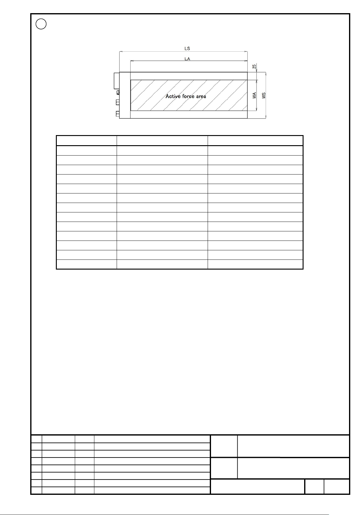
FANUC CORPORATION
Ed
Date
Design
Description
B-65382EN/05-06
Akasako
01
Newly designed
/87
Drawing
Akasako
02
Add M3 model, Correct
Model name
LS × WS for coil slider
LA × WA for active force area
LiS 4500M3/2HV-B
LiS 4500M3/2-B
LiS 7000M3/2HV-B
LiS 7000M3/2-B
LiS 7000M3/4-B
LiS 9000M3/2HV-B
LiS 9000M3/2-B
LiS 11000M3/2HV-B
LiS 11000M3/2-B
LiS 14000M3/2HV-B
LiS 14000M3/2-B
LiS 16000M3/2HV-B
LiS 16000M3/2-B
02
M3 model
305 × 200 268 × 150
305 × 200 268 × 150
425 × 200 388 × 150
425 × 200 388 × 150
425 × 200 388 × 150
545 × 200 508 × 150
545 × 200 508 × 150
665 × 200 628 × 150
665 × 200 628 × 150
785 × 200 748 × 150
785 × 200 748 × 150
905 × 200 868 × 150
905 × 200 868 × 150
FANUC LINEAR MOTOR LiS-B series
S1, S2, M2, M3 Model
No.
Page
77
Page 78
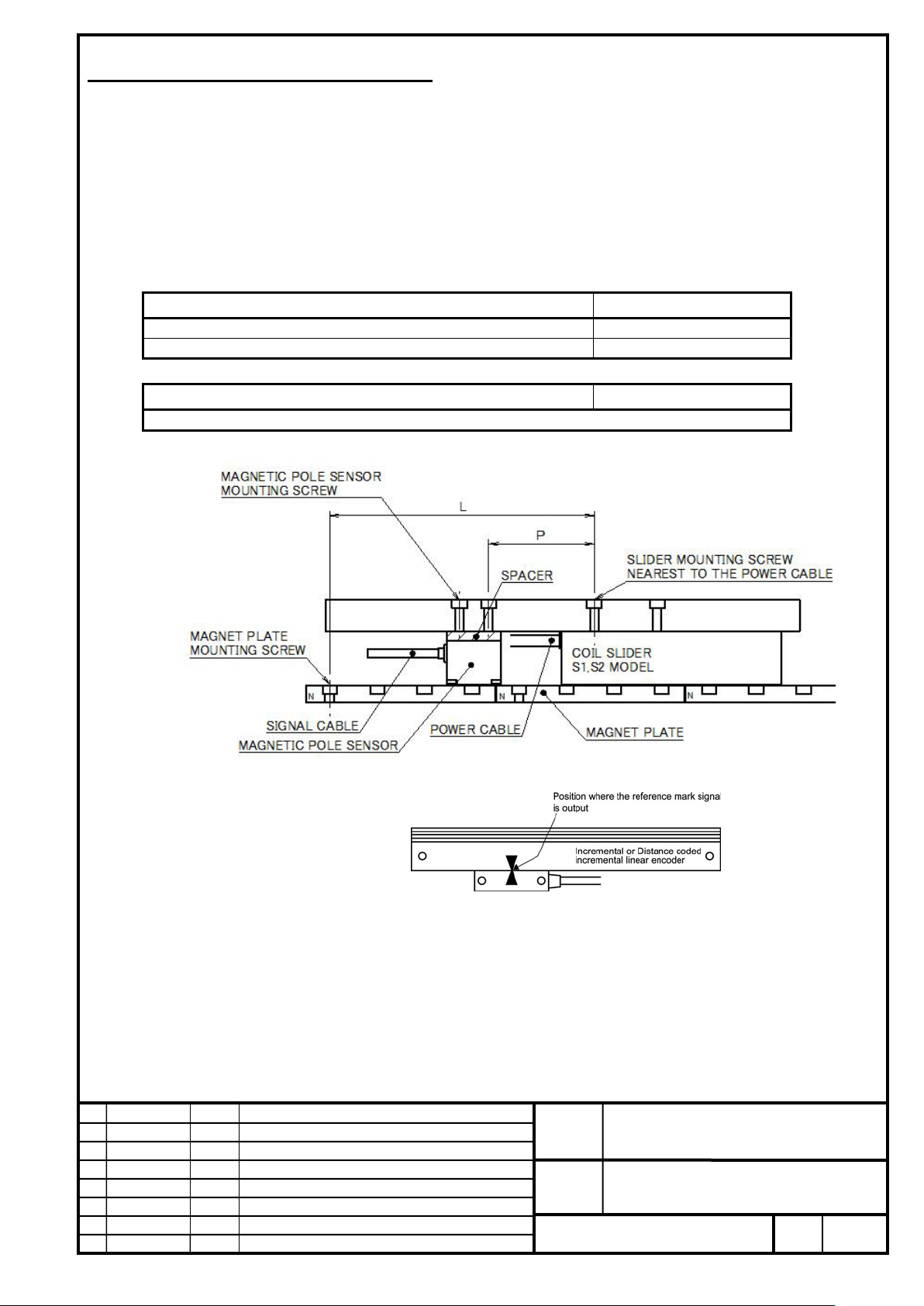
FANUC CORPORATION
Ed
Date
Design
Description
B-65382EN/05-06
Akasako
01
Newly designed
/87
Drawing
Akasako
02
Add M3 model, Correct
Magnet end face on the power line side
L (mm) *M=1,2,3,…
N pole (in case of figure below)
L=30×M+17.5±0.5 (mm)
S pole
L=30×M+32.5±0.5 (mm)
Mounted hole pitch between coil slider and magnetic pole sensor
P (mm) *N=1,2,3,…
P=30×N+6.8 (mm)
11. Linear Encoder Mounting Positions
11-1 Incremental Linear Encoder
For Linear motor LiS-B series, the magnetic pole sensor cannot be directly attached to the coil slider. Accordingly, the
positional relationship for mounting the linear encoder and the magneti c pol e s ensor is predetermined.
For S1, S2 model
Mount the linear motor, magnetic pole sensor, and linear encoder in the place where the conditions stated in the above
figure and expression are satisfied simultaneously.
(Above figure shows the case that “Magnet end face on the power line side” is N-pole.)
FANUC LINEAR MOTOR LiS-B series
S1, S2, M2, M3 Model
No.
Page
78
Page 79

FANUC CORPORATION
Ed
Date
Design
Description
B-65382EN/05-06
Akasako
01
Newly designed
/87
Drawing
Akasako
02
Add M3 model, Correct
NOTE
1 With the FANUC LINEAR MOTOR LiS-B series, an incremental linear encoder that outputs the
reference mark signal (Z-phase signal) at one position only is required. S pecify this requirement to
the manufacturer when ordering an incremental linear encoder. If an incremental linear encoder
has two positions where the reference mark signal is output, a count miss alarm may be issued
when the second reference mark signal is detected.
2 To mount the magnetic pole sensor, the customers are kindly requested to get the spacers shown
below ready on their own.
* For S1, S2 model (Not M2 model)
Not using t he cooling plate : t = 6mm
Using the cooling plat e : t = 14mm
No.
FANUC LINEAR MOTOR LiS-B series
S1, S2, M2, M3 Model
Page
79
Page 80
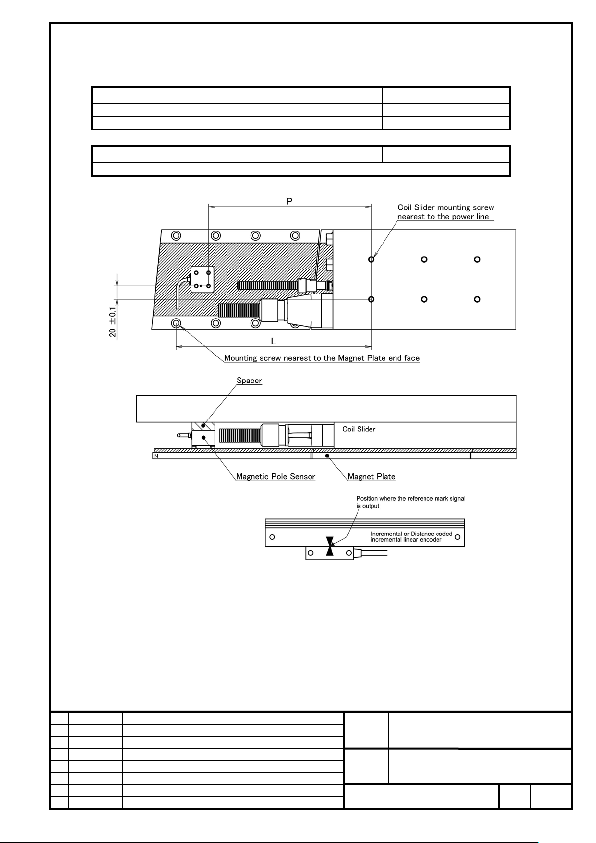
FANUC CORPORATION
Ed
Date
Design
Description
B-65382EN/05-06
Akasako
01
Newly designed
/87
Drawing
Akasako
02
Add M3 model, Correct
Magnet end face on the power line (connector) side
L (mm) *M=2,3,4,…
N pole (in case of figure below)
L=60×M+55±0.5 (mm)
S pole
L=60×M+25±0.5 (mm)
Mounted hole pitch between coil slider and magnetic pole sensor
P (mm) *N=2,3,4,…
P=60×N+6 (mm)
For M2 model
Mount the linear motor, magnetic pole sensor, and linear encoder in the place where the conditions stated in the above
figure and expression are satisfied simultaneously.
(Above figure shows the case that “Magnet end face on the power line side” is N-pole.)
FANUC LINEAR MOTOR LiS-B series
S1, S2, M2, M3 Model
No.
Page
80
Page 81
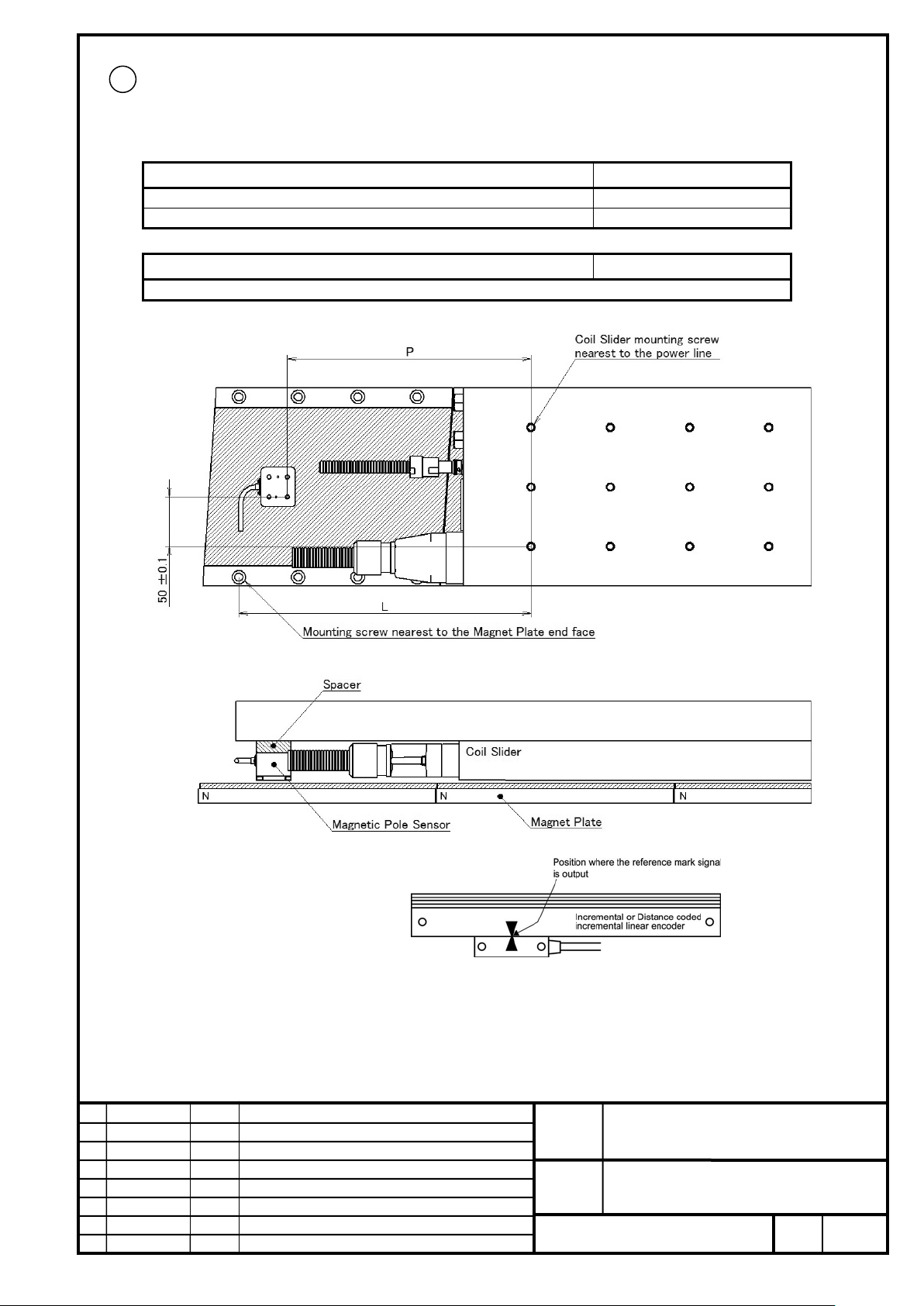
FANUC CORPORATION
Ed
Date
Design
Description
B-65382EN/05-06
Akasako
01
Newly designed
/87
Drawing
Akasako
02
Add M3 model, Correct
Magnet end face on the power line (connector) side
L (mm) *M=2,3,4,…
N pole (in case of figure below)
L=60×M+55±0.5 (mm)
S pole
L=60×M+25±0.5 (mm)
Mounted hole pitch between coil slider and magnetic pole sensor
P (mm) *N=2,3,4,…
P=60×N+6 (mm)
02
For M3 model
Mount the linear motor, magnetic pole sensor, and linear encoder in the place where the conditions stated in the above
figure and expression are satisfied simultaneously.
(Above figure shows the case that “Magnet end face on the power line side” is N-pole.)
FANUC LINEAR MOTOR LiS-B series
S1, S2, M2, M3 Model
No.
Page
81
Page 82

FANUC CORPORATION
Ed
Date
Design
Description
B-65382EN/05-06
Akasako
01
Newly designed
/87
Drawing
Akasako
02
Add M3 model, Correct
NOTE
1 With the FANUC LINEAR MOTOR LiS-B series, an incremental linear encoder that outputs the
reference mark signal (Z-phase signal) at one position only is required. S pecify this requirement to
the manufacturer when ordering an incremental linear encoder. If an increm ental linear encoder
has two positions where the reference mark signal is output, a count miss alarm may be issued
when the second reference mark signal is detected.
2 To mount the magnetic pole sensor, the customers are kindly requested to get the spacers shown
below ready on their own.
* For M2, M3 model (Not S1, S2 model)
No.
FANUC LINEAR MOTOR LiS-B series
S1, S2, M2, M3 Model
Page
82
Page 83
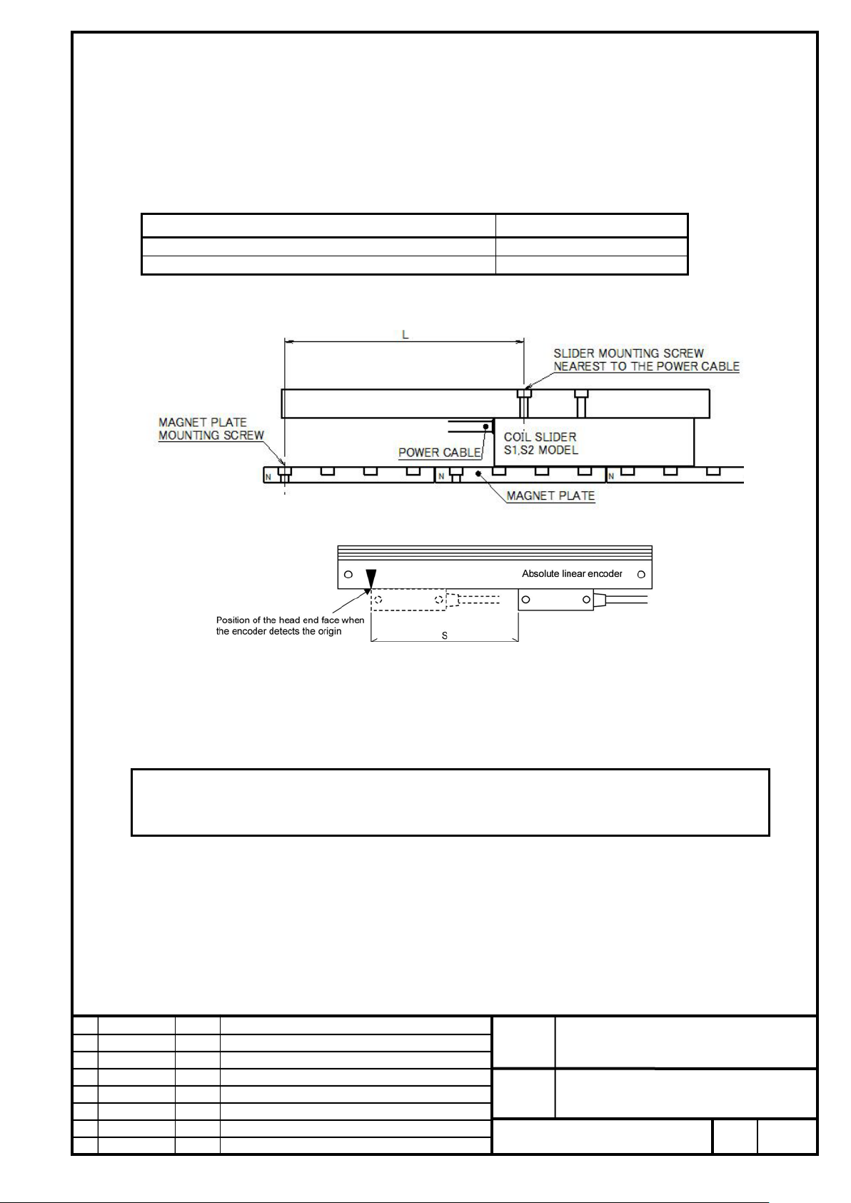
FANUC CORPORATION
Ed
Date
Design
Description
B-65382EN/05-06
Akasako
01
Newly designed
/87
Drawing
Akasako
02
Add M3 model, Correct
Magnet end face on the power line side
L (mm) *M=0,1,2,…
N pole (in case of figure below)
L=30×M+17.5±0.5 (mm)
S pole
L=30×M+2.5±0.5 (mm)
encoder manufacturer or a dealer of the manufacturer.
11-2 Absolute Linear Encoder
The positional relationship between the linear motor and the absolute linear encoder is predetermined. The following
positional relationships and expressions must be satisfied at the same time.
For S1, S2 model
S=30×N (mm) N=1,2,3,…
Mount the linear motor, linear encoder in the place where the conditions stated in the above figure and expression are
satisfied simultaneously.
(Above figure shows the case that “Magnet end face on the power line side” is N-pole.)
NOTE
The base point of a linear encoder differs with the encoder. For details or questions, contact the
No.
FANUC LINEAR MOTOR LiS-B series
S1, S2, M2, M3 Model
Page
83
Page 84

FANUC CORPORATION
Ed
Date
Design
Description
B-65382EN/05-06
Akasako
01
Newly designed
/87
Drawing
Akasako
02
Add M3 model, Correct
Magnet end face on the power line (connector) side
L (mm) *M=0,1,2,…
N pole (in case of figure below)
L=60×M+55±0.5 (mm)
S pole
L=60×M+25±0.5 (mm)
encoder manufacturer or a dealer of the manufacturer.
02
For M2, M3 model
S=60×N (mm) N=1,2,3,…
Mount the linear motor, linear encoder in the place where the conditions stated in the above figure and expression are
satisfied simultaneously.
(Above figure shows the case that “Magnet end face on the power line side” is N-pole.)
NOTE
The base point of a linear encoder differs with the encoder. For details or questions, contact the
FANUC LINEAR MOTOR LiS-B series
S1, S2, M2, M3 Model
No.
Page
84
Page 85

FANUC CORPORATION
Ed
Date
Design
Description
B-65382EN/05-06
Akasako
01
Newly designed
/87
Drawing
Akasako
02
Add M3 model, Correct
Model
Applicable DBM specification
A
B
LiS 300S1/4-B *
LiS 600S1/4-B
LiS 900S1/4-B
LiS 600S2/3-B *
LiS 1200S2/3-B
LiS 1800S2/3-B
LiS 3000M2/2-B
LiS 4500M2/2-B
LiS 6000M2/2-B
LiS 7500M2/2-B
LiS 9000M2/2-B
-4
LiS 4500M3/2-B
LiS 7000M3/2-B
A06B-6079-H401, -H403
3.15 × 10⁻⁴
2.70 × 10⁻⁵
LiS 9000M3/2-B
LiS 11000M3/2-B
A06B-6079-H401, -H403
1.09 × 10⁻⁴
2.00 × 10⁻⁵
A06B-6069-H300, -H301
1.61 × 10⁻⁴
1.36 × 10⁻⁵
-4
A06B-6069-H300, -H301
1.52 × 10⁻⁴
1.08 × 10⁻⁵
Applicable amplifier specification
Name
Specification
αiSV 20/40
A06B-6240-H206
αiSV 20/20/40
A06B-6240-H306, -H326
αiSV 20/40
A06B-6240-H206
αiSV 20/20/40
A06B-6240-H306, -H326
12. Amount of Travel when Dynamic Brake
When a dynamic brake is applied, the moving object coasts before it comes to a complete stop. The coasting distance is
calculated as follows:
Coasting distance (m) = VM×(t1+t2)+MT×(A×VM+B×VM3)
Where VM: Motor speed (m/s)
t1+t2: Control delay time, usually about 0.05 sec
MT: Mass of the moving object (kg)
A and B: Values specific to each motor model, which are as listed below:
02
Input power voltage : 200V
Built into the servo amplifier 4.32 × 10⁻³ 3.48 × 10⁻³
Built into the servo amplifier 5.15 × 10⁻³ 7.36 × 10⁻⁴
Built into the servo amplifier 3.68 × 10⁻³ 4.94 × 10⁻⁴
Built into the servo amplifier 1.77 × 10⁻³ 1.75 × 10⁻³
Built into the servo amplifier 1.63 × 10⁻³ 4.80 × 10⁻⁴
Built into the servo amplifier 1.15 × 10⁻³ 3.28 × 10⁻⁴
Built into the servo amplifier 5.89 × 10⁻⁴ 8.27 × 10⁻⁵
Built into the servo amplifier 4.97 × 10⁻⁴ 4.35 × 10⁻⁵
Built into the servo amplifier 2.63 × 10⁻⁴ 4.63 × 10⁻⁵
Built into the servo amplifier 2.36 × 10⁻⁴ 3.30 × 10⁻⁵
Built into the servo amplifier 2.17 × 10⁻⁴ 2.49 × 10⁻⁵
LiS 11000M2/2-B
A06B-6079-H401, -H403 1.42 × 10
A06B-6069-H300, -H301 2.05 × 10⁻⁴ 1.94 × 10⁻⁵
Built into the servo amplifier 4.31 × 10⁻⁴ 4.48 × 10⁻⁵
Built into the servo amplifier 2.17 × 10⁻⁴ 3.95 × 10⁻⁵
2.80 × 10⁻⁵
LiS 7000M3/4-B
LiS 14000M3/2-B
LiS 16000M3/2-B
* When the following servo amplifiers are used, the coefficients for dynamic brake calculation differ from those list ed
above.
Model
LiS 300S1/4-B
LiS 600S2/3-B
A06B-6069-H300, -H301 5.14 × 10⁻⁴ 1.65 × 10⁻⁵
Built into the servo amplifier 1.90 × 10⁻⁴ 2.51 × 10⁻⁵
Built into the servo amplifier 1.73 × 10⁻⁴ 1.84 × 10⁻⁵
A06B-6079-H401, -H403 1.00 × 10
1.64 × 10⁻⁵
A B
7.28 × 10⁻³ 2.06 × 10⁻³
2.51 × 10⁻³ 1.24 × 10⁻³
FANUC LINEAR MOTOR LiS-B series
S1, S2, M2, M3 Model
No.
Page
85
Page 86
FANUC CORPORATION
Ed
Date
Design
Description
B-65382EN/05-06
Akasako
01
Newly designed
/87
Drawing
Akasako
02
Add M3 model, Correct
Model
Applicable DBM specification
A
B
LiS 300S1/4-B
LiS 600S1/4-B
LiS 900S1/4-B
LiS 600S2/3-B
LiS 1200S2/3-B
LiS 1800S2/3-B
LiS 3000M2/2HV-B
LiS 3000M2/2-B
LiS 4500M2/2HV-B
LiS 4500M2/2-B
LiS 6000M2/2HV-B
-4
LiS 7500M2/2HV-B
-4
A06B-6069-H300, -H301
2.36 × 10⁻⁴
3.30 × 10⁻⁵
LiS 9000M2/2HV-B
A06B-6079-H401, -H403
1.55 × 10⁻⁴
3.51 × 10⁻⁵
A06B-6069-H300, -H301
2.17 × 10⁻⁴
2.49 × 10⁻⁵
LiS 11000M2/2HV-B
A06B-6079-H401, -H403
1.42 × 10⁻⁴
2.80 × 10⁻⁵
LiS 4500M3/2HV-B
LiS 4500M3/2-B
LiS 7000M3/2HV-B
-4
LiS 9000M3/2HV-B
-4
A06B-6069-H300, -H301
1.90 × 10⁻⁴
2.51 × 10⁻⁵
LiS 11000M3/2HV-B
A06B-6079-H401, -H403
1.21 × 10⁻⁴
2.63 × 10⁻⁵
A06B-6069-H300, -H301
1.73 × 10⁻⁴
1.84 × 10⁻⁵
-5
A06B-6069-H300, -H301
8.25 × 10⁻⁵
2.61 × 10⁻⁵
-4
A06B-6079-H401, -H403
6.16 × 10⁻⁵
2.66 × 10⁻⁵
A06B-6069-H300, -H301
1.52 × 10⁻⁴
1.08 × 10⁻⁵
02
Input power voltage : 400V
LiS 6000M2/2-B
LiS 7500M2/2-B
Built into the servo amplifier 1.32 × 10⁻² 1.14 × 10⁻³
Built into the servo amplifier 8.86 × 10⁻³ 4.28 × 10⁻⁴
Built into the servo amplifier 8.13 × 10⁻³ 2.24 × 10⁻⁴
Built into the servo amplifier 3.99 × 10⁻³ 7.77 × 10⁻⁴
Built into the servo amplifier 2.56 × 10⁻³ 3.06 × 10⁻⁴
Built into the servo amplifier 2.26 × 10⁻³ 1.66 × 10⁻⁴
Built into the servo amplifier 4.66 × 10⁻⁴ 1.06 × 10⁻⁴
Built into the servo amplifier 1.22 × 10⁻³ 4.01 × 10⁻⁵
Built into the servo amplifier 3.77 × 10⁻⁴ 5.83 × 10⁻⁵
Built into the servo amplifier 1.12 × 10⁻³ 1.93 × 10⁻⁵
Built into the servo amplifier 3.32 × 10⁻⁴ 3.72 × 10⁻⁵
A06B-6079-H401, -H403 2.00 × 10
6.07 × 10⁻⁵
A06B-6069-H300, -H301 2.63 × 10⁻⁴ 4.63 × 10⁻⁵
Built into the servo amplifier 3.05 × 10⁻⁴ 2.59 × 10⁻⁵
A06B-6079-H401, -H403 1.73 × 10
4.49 × 10⁻⁵
LiS 9000M2/2-B
LiS 11000M2/2-B
LiS 7000M3/2-B
LiS 9000M3/2-B
LiS 11000M3/2-B
LiS 14000M3/2HV-B
LiS 14000M3/2-B
Built into the servo amplifier 2.87 × 10⁻⁴ 1.91 × 10⁻⁵
Built into the servo amplifier 2.75 × 10⁻⁴ 1.47 × 10⁻⁵
A06B-6069-H300, -H301 2.05 × 10⁻⁴ 1.94 × 10⁻⁵
Built into the servo amplifier 3.59 × 10⁻⁴ 5.01 × 10⁻⁵
Built into the servo amplifier 9.49 × 10⁻⁴ 2.04 × 10⁻⁵
Built into the servo amplifier 3.02 × 10⁻⁴ 2.74 × 10⁻⁵
A06B-6079-H401, -H403 1.66 × 10
5.18 × 10⁻⁵
A06B-6069-H300, -H301 2.17 × 10⁻⁴ 3.95 × 10⁻⁵
Built into the servo amplifier 2.74 × 10⁻⁴ 1.76 × 10⁻⁵
A06B-6079-H401, -H403 1.38 × 10
3.45 × 10⁻⁵
Built into the servo amplifier 2.56 × 10⁻⁴ 1.22 × 10⁻⁵
A06B-6079-H401, -H403 7.00 × 10
A06B-6079-H401, -H403 1.09 × 10
3.08 × 10⁻⁵
2.00 × 10⁻⁵
A06B-6069-H300, -H301 1.61 × 10⁻⁴ 1.36 × 10⁻⁵
LiS 16000M3/2HV-B
LiS 16000M3/2-B
A06B-6069-H300, -H301 7.41 × 10⁻⁵ 2.21 × 10⁻⁵
A06B-6079-H401, -H403 1.00 × 10
-4
1.64 × 10⁻⁵
FANUC LINEAR MOTOR LiS-B series
S1, S2, M2, M3 Model
No.
Page
86
Page 87

FANUC CORPORATION
Ed
Date
Design
Description
B-65382EN/05-06
Akasako
01
Newly designed
/87
Drawing
Akasako
02
Add M3 model, Correct
• If you want to use the Servo Amplifier βi series, contact FANUC.
NOTE
• When only the dynamic brake is used, the required sufficient braking distance may not be obtained (the
linear motor may coast longer). In this case, please consider auxiliary brake systems such as stoppers or
dampers at the ends of an axis and an external mechanical brake to protect the machine.
• FANUC recommends the use of quick stop functions as a function f or shortening the stop distance at
emergency stop or a power failure. For details, refer to “SERVO F UNCTION DETAILS” in “Parameter
Manual” (B-65270EN). To operate the quick stop function at a power failure properly, maintain the control
power to the CNC and servo amplifier (24 VDC) using an uninterruptible power supply (UPS).
• If an alarm is issued, the stop distance cannot be shortened because the quic k stop function does not
operate.
• If you want to use a quick stop function, be sure to use the actual machine to check that the motor stop
distance is shortened at emergency stop or a power failure.
13. Position detection circuit and Temperature detection circuit
Linear motor LiS-B series has PTC thermistor instead of thermostat for overheating protection.
Therefore,Position detection circuit or Temperature detection circuit corresponding t o P TC thermistor is required.
Temperature detection circuit : A860-2092-T301 ( Technical report No.B-65382EN/05-02 )
Temperature detection circuit (EXTERNAL CONTACT OUTPUT TYPE)
: A860-2094-T301 ( Technical r eport No.B-65382EN/05-05 )
Position detection circuit (1 output) : A860-2034-T201 ( Technical report No.B-65382EN/05-03 )
Position detection circuit (2 outputs) : A860-2034-T202 ( Technical report No.B-65382EN/05-03 )
For temperature monitor, NTC thermis tor is adopted same as conventional model.
No.
FANUC LINEAR MOTOR LiS-B series
S1, S2, M2, M3 Model
Page
87
 Loading...