

Page 1

A
FANUC SYNCHRONOUS BUILT-IN SERVO MOTOR D
1.Type of applied technical documents
D
iS 180/800-B, DiS 600/600-B
iS-B series DESCRIPTIONS
Name
Spec.No./Ed.
2.Summary of Change
Group Name/Outline
Basic
Optional
Function
SYNCHRONOUS BUILT-IN SERVO MOTOR DiS-B series
DiS 180/800-B and DiS 600/600-B
Unit
Maintenance
Parts
Notice
FANUC SYNCHRONOUS BUILT-IN SERVO MOTOR
DiS-B series DESCRIPTIONS
A-90200-0220EN/01
New, Add,
Correct, Delete
Applicable
Date
Add January, 2018
Correction
Another
01 18.01.26 Y.Sugimoto Newly Designed Senoo
Edit Date Design Description
Title.
FANUC CYNCHRONOUS BUILT-IN
SERVO MOTOR DiS-B series
DESCRIPTIONS
Draw.No..
-90200-0220EN/01
Sheet.
CUST.
1/29
Page 2
A
PREFACE
This manual covers information on the following models:
(These model names described in this manual may be changed in the future.)
Synchronous Built-in Servo Motor DiS-B series
DiS 180/800-B (A06B-2323-B330)
DiS 600/600-B (A06B-2331-B440)
Regarding acceptance, storage, selection, start-up etc. not described in this manual, please refer to
FANUC SYNCHRONOUS BUILT-IN SERVO MOTOR DiS-B series DESCRIPTIONS (B-65492EN) or
FANUC SYNCHRONOUS BUILT-IN SERVO MOTOR DiS series DESCRIPTIONS (B-65332EN).
Title.
FANUC CYNCHRONOUS BUILT-IN
01 18.01.26 Y.Sugimoto Newly Designed Senoo
Edit Date Design Description
SERVO MOTOR DiS-B series
DESCRIPTIONS
Draw.No..
-90200-0220EN/01
CUST.
Sheet.
2/29
Page 3
A
Related manuals
There are the following nine manuals that are related to Synchronous Built-in Servo Motor DiS-B series. In the table,
this manual is marked with an asterisk (*).
Document name
FANUC SYNCHRONOUS BUILT-IN SERVO
MOTOR DiS-B series model addition
FANUC SYNCHRONOUS BUILT-IN SERVO
MOTOR DiS-B series DESCRIPTIONS
FANUC SYNCHRONOUS BUILT-IN SERVO
MOTOR DiS series DESCRIPTIONS
FANUC SERVO AMPLIFIER i-B series
DESCRIPTIONS
FANUC AC SERVO MOTOR i-B/i series
DESCRIPTIONS
FANUC AC SPINDLE MOTOR i-B /i-B series
DESCRIPTIONS
FANUC BUILT-IN SPINDLE MOTOR BiI–B
series
DESCRIPTIONS
FANUC SYNCHRONOUS BUILT-IN SPINDLE
MOTOR BiS-B series
DESCRIPTIONS
FANUC AC SERVO MOTOR i series
FANUC AC SERVO MOTOR i series
FANUC LINEAR MOTOR LiS series
FANUC SYNCHRONOUS BUILT-IN SERVO
MOTOR DiS series
PARAMETER MANUAL
(Referred to below as the “Parameter Manual”.)
This manual does not cover information related to the connection with servo amplifiers and CNCs. For details of
connection, refer to the following manuals:
FANUC SERVO AMPLIFIER i-B series DESCRIPTIONS (B-65412EN)
If you want to use a synchronous built-in server motor for a spindle, refer to the notes described in the following
manuals as needed:
FANUC AC SPINDLE MOTOR i-B/i-B series DESCRIPTIONS(B-65452EN)
FANUC BUILT-IN SPINDLE MOTOR BiI-B series DESCRIPTIONS(B-65462EN)
FANUC BUILT-IN SPINDLE MOTOR BiS-B series DESCRIPTIONS(B-65472EN)
Document
number
A-90200-0210EN
B-65492EN
B-65332EN
B-65412EN
B-65262EN
B-65452EN
B-65462EN
B-65472JEN
B-65270EN
Major contents Major usage
Specification
External dimensions
Specification
External dimensions
Connections
Specification
External dimensions
Connections
Specifications and
functions
Installation
External dimensions
and maintenance area
Connections
Specification
Characteristics
External dimensions
Specification
Notes on operation
Specification
General information on
assembly
Specification
Spindle structure
Initial setting
Setting parameters
Description of
parameters
Selection of motor
Selection of motor
Connection of motor
Start up the system
(Hardware)
Selection of motor
Connection of motor
Start up the system
(Hardware)
Selection of amplifier
Connection of
amplifier
Reference of terms
Selection of motor
Reference of terms
Reference of
precautions (for
spindles)
Reference of
precautions (for
spindles)
Reference of
precautions (for
spindles)
Start up the system
(Software)
Turning the system
(Parameters)
*
Title.
FANUC CYNCHRONOUS BUILT-IN
01 18.01.26 Y.Sugimoto Newly Designed Senoo
Edit Date Design Description
SERVO MOTOR DiS-B series
DESCRIPTIONS
Draw.No..
-90200-0220EN/01
CUST.
Sheet.
3/29
Page 4

A
1 SPECIFICATIONS
1.1 Data Sheets
Contents
1.1.1 Input power voltage : 200V ................................................................................................................................ 5
DiS 180/800-B (A06B-2323-B330) .............................................................................................................. 5
DiS 600/600-B (A06B-2331-B440) .............................................................................................................. 7
1.1.2 Input power voltage : 400V ................................................................................................................................ 9
DiS 180/800-B (A06B-2323-B330) .............................................................................................................. 9
DiS 600/600-B (A06B-2331-B440) ............................................................................................................ 11
Title.
FANUC CYNCHRONOUS BUILT-IN
01 18.01.26 Y.Sugimoto Newly Designed Senoo
Edit Date Design Description
SERVO MOTOR DiS-B series
DESCRIPTIONS
Draw.No..
-90200-0220EN/01
CUST.
Sheet.
4/29
Page 5
A
1
x
1
x
1
x
1.1.1 Input power voltage : 200V
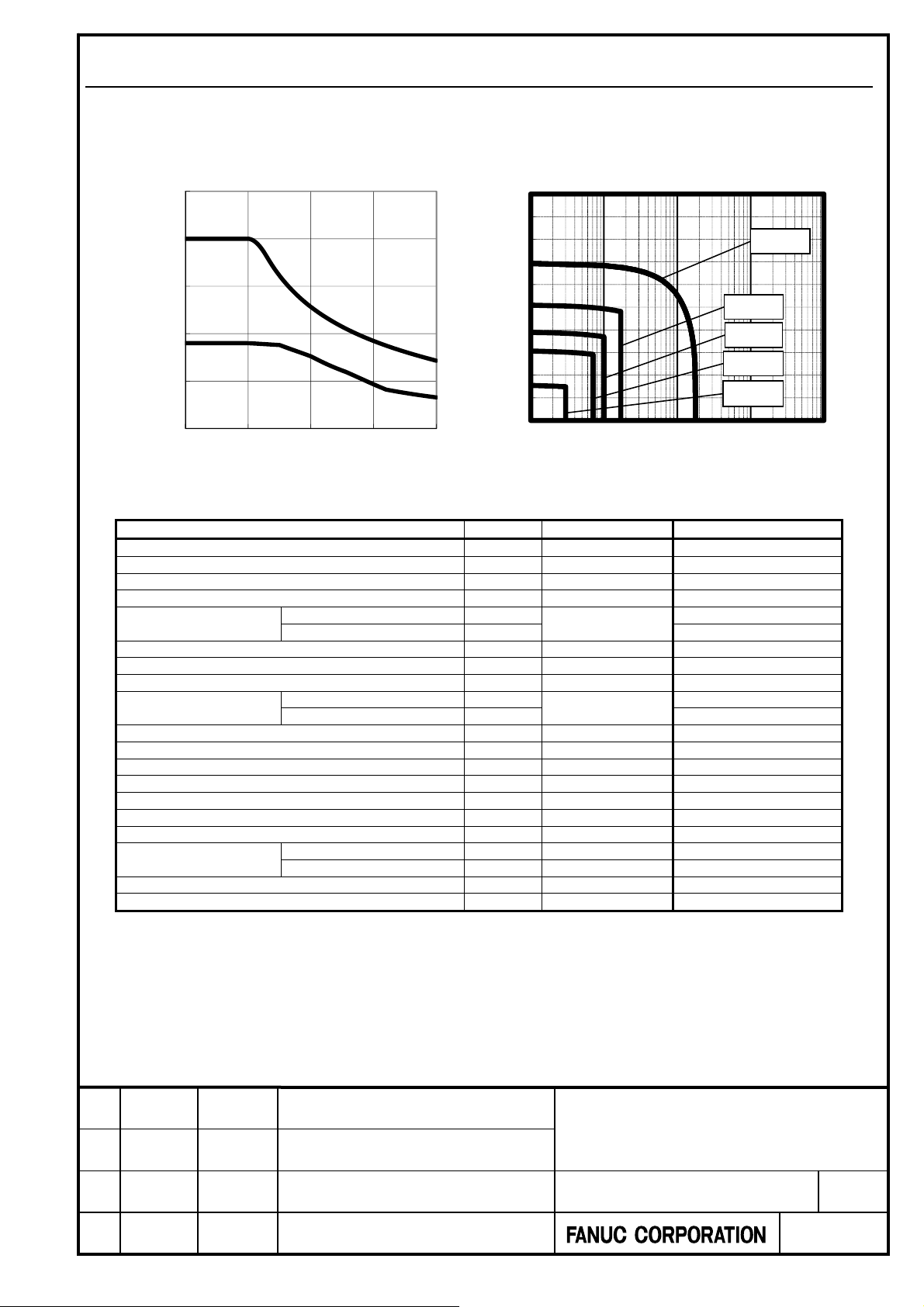
DiS 180/800-B (A06B-2323-B330) 200V oil cooling
Torque-speed graph Overload duty characteristic
500
100%
90%
400
80%
120%
70%
300
Intermittent operation
200
Torque(Nm)
100
Continuous operation
0
0 100 200 300 400
Speed(min-1)
Specifications
Items Symbol Unit Specification
Input power voltage - V 200
Rated output (*) Pr kW 3.2
Rated torque (*) Tr Nm 111
Rated speed Nr min
Continuous torque (*)
Maximum torque (*) T
Upper speed for the maximum torque - min
Maximum speed N
Continuous current (*)
Maximum current I
Torque constant(*) Kt Nm/Arms 9.8
Winding resistance (between terminals) (*) Ra Ω 2.60
Thermal time constant tt min. 2
Required cooling capacity - W 2000
Flow rate Q L/min. 15
Moment of inertia of rotor Jm kgm2 0.026
Mass
Number of poles P Pole 28
Maximum current of the applicable amplifier - Ap 80
(*): Indicates the standard value at a temperature of 20C. (10%)
The values may vary depending on the ambient temperature, series and edition of servo software, parameters,
input power supply voltage, servo amplifier specifications, individual motor difference, and others.
The values are subject to change without notice.
When liquid cooling is used, some parameters must be changed.
The overload duty characteristic is calculated based on the thermal characteristic of the running motor. The on
time may become shorter at 0 [min
At low speed Tc
At a stop Ts 146
At low speed Ic
At a stop Is 15.9
Stator W
Rotor Wr kg 4.6
-1
].
60%
duty [%]
50%
40%
30%
20%
10%
140%
160%
180%
MAX
0%
1 10 100 1000 10000
ON time [sec]
-
275
Nm
Nm 400
ma
min
ma
Arms 50.9
ma
kg 14
s
-
100
-
400
Arms
180
20.2
Title.
FANUC CYNCHRONOUS BUILT-IN
01 18.01.26 Y.Sugimoto Newly Designed Senoo
Edit Date Design Description
SERVO MOTOR DiS-B series
DESCRIPTIONS
Draw.No..
-90200-0220EN/01
CUST.
Sheet.
5/29
Page 6

A
1
x
1
x
1
x
DiS 180/800-B (A06B-2323-B330) 200V no cooling
Torque-speed graph Overload duty characteristic
500
100%
90%
400
80%
120%
70%
300
Intermittent operation
200
Torque(Nm)
100
Continuous operation
0
0 100 200 300 400
Speed(min-1)
Specifications
Items Symbol Unit Specification
Input power voltage - V 200
Rated output (*) Pr kW 1.3
Rated torque (*) Tr Nm 69
Rated speed Nr min
Continuous torque (*)
Maximum torque (*) T
Upper speed for the maximum torque - min
Maximum speed N
Continuous current (*)
Maximum current I
Torque constant(*) Kt Nm/Arms 9.8
Winding resistance (between terminals) (*) Ra Ω 2.60
Thermal time constant tt min. 80
Required cooling capacity - W -
Flow rate Q L/min. -
Moment of inertia of rotor Jm kgm2 0.026
Mass
Number of poles P Pole 28
Maximum current of the applicable amplifier - Ap 80
(*): Indicates the standard value at a temperature of 20C. (10%)
The values may vary depending on the ambient temperature, series and edition of servo software, parameters,
input power supply voltage, servo amplifier specifications, individual motor difference, and others.
The values are subject to change without notice.
The overload duty characteristic is calculated based on the thermal characteristic of the running motor. The on
time may become shorter at 0 [min
At low speed Tc
At a stop Ts 75
At low speed Ic
At a stop Is 8.6
Stator W
Rotor Wr kg 4.6
-1
].
60%
duty [%]
50%
40%
30%
20%
10%
140%
160%
180%
MAX
0%
1 10 100 1000 10000
ON time [sec]
-
180
Nm
Nm 400
ma
min
ma
Arms 50.9
ma
kg 14
s
-
100
-
400
Arms
75
8.6
Title.
FANUC CYNCHRONOUS BUILT-IN
01 18.01.26 Y.Sugimoto Newly Designed Senoo
Edit Date Design Description
SERVO MOTOR DiS-B series
DESCRIPTIONS
Draw.No..
-90200-0220EN/01
CUST.
Sheet.
6/29
Page 7

A
1
x
1
x
1
x
DiS 600/600-B (A06B-2331-B440) 200V oil cooling
Torque-speed graph Overload duty characteristic
1400
1200
1000
800
Intermittent operation
600
Torque(Nm)
400
200
Continuous operation
0
0 100 200 300
Speed(min-1)
Specifications
Items Symbol Unit Specification
Input power voltage - V 200
Rated output (*) Pr kW 7.8
Rated torque (*) Tr Nm 248
Rated speed Nr min
Continuous torque (*)
Maximum torque (*) T
Upper speed for the maximum torque - min
Maximum speed N
Continuous current (*)
Maximum current I
Torque constant(*) Kt Nm/Arms 13.3
Winding resistance (between terminals) (*) Ra Ω 0.71
Thermal time constant tt min. 3
Required cooling capacity - W 2800
Flow rate Q L/min. 15
Moment of inertia of rotor Jm kgm2 0.14
Mass
Number of poles P Pole 42
Maximum current of the applicable amplifier - Ap 160
(*): Indicates the standard value at a temperature of 20C. (10%)
The values may vary depending on the ambient temperature, series and edition of servo software, parameters,
input power supply voltage, servo amplifier specifications, individual motor difference, and others.
The values are subject to change without notice.
When liquid cooling is used, some parameters must be changed.
The overload duty characteristic is calculated based on the thermal characteristic of the running motor. The on
time may become shorter at 0 [min
At low speed Tc
At a stop Ts 530
At low speed Ic
At a stop Is 42.8
Stator Ws kg 21
Rotor Wr kg 11
-1
].
100%
90%
80%
70%
60%
duty [%]
50%
40%
30%
20%
10%
140%
160%
180%
MAX
0%
1 10 100 1000 10000
ON time [sec]
-
300
Nm
Nm 1200
ma
min
ma
Arms 113
ma
-
100
-
300
Arms
550
45.0
120%
Title.
FANUC CYNCHRONOUS BUILT-IN
01 18.01.26 Y.Sugimoto Newly Designed Senoo
Edit Date Design Description
SERVO MOTOR DiS-B series
DESCRIPTIONS
Draw.No..
-90200-0220EN/01
CUST.
Sheet.
7/29
Page 8
A
1
x
1
x
1
x
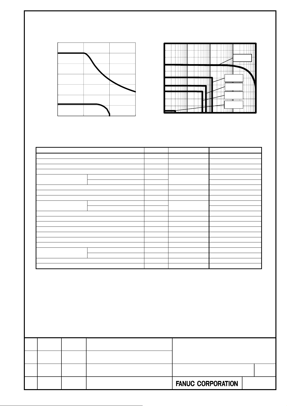
DiS 600/600-B (A06B-2331-B440) 200V no cooling
Torque-speed graph Overload duty characteristic
1400
1200
1000
800
600
Torque(Nm)
400
Intermittent operation
200
Continuous operation
0
0 100 200 300
Speed(min-1)
Specifications
Items Symbol Unit Specification
Input power voltage - V 200
Rated output (*) Pr kW 3.5
Rated torque (*) Tr Nm 213
Rated speed Nr min
Continuous torque (*)
Maximum torque (*) T
Upper speed for the maximum torque - min
Maximum speed N
Continuous current (*)
Maximum current I
Torque constant(*) Kt Nm/Arms 13.3
Winding resistance (between terminals) (*) Ra Ω 0.71
Thermal time constant tt min. 150
Required cooling capacity - W -
Flow rate Q L/min. -
Moment of inertia of rotor Jm kgm2 0.14
Mass
Number of poles P Pole 42
Maximum current of the applicable amplifier - Ap 160
(*): Indicates the standard value at a temperature of 20C. (10%)
The values may vary depending on the ambient temperature, series and edition of servo software, parameters,
input power supply voltage, servo amplifier specifications, individual motor difference, and others.
The values are subject to change without notice.
The overload duty characteristic is calculated based on the thermal characteristic of the running motor. The on
time may become shorter at 0 [min
At low speed Tc
At a stop Ts 226
At low speed Ic
At a stop Is 18.9
Stator Ws kg 24
Rotor Wr kg 11
-1
].
100%
90%
80%
70%
60%
duty [%]
50%
40%
30%
20%
10%
140%
160%
180%
MAX
0%
1 10 100 1000 10000
ON time [sec]
-
160
Nm
Nm 1200
ma
min
ma
Arms 113
ma
-
100
-
300
Arms
18.9
120%
226
Title.
FANUC CYNCHRONOUS BUILT-IN
01 18.01.26 Y.Sugimoto Newly Designed Senoo
Edit Date Design Description
SERVO MOTOR DiS-B series
DESCRIPTIONS
Draw.No..
-90200-0220EN/01
CUST.
Sheet.
8/29
Page 9

A
1
x
1
x
1
x
1.1.2 Input power voltage : 400V
DiS 180/800-B (A06B-2323-B330) 400V oil cooling
Torque-speed graph Overload duty characteristic
500
100%
90%
400
80%
120%
70%
300
Intermittent operation
200
Torque(Nm)
100
Continuous operation
0
0 200 400 600 800
Speed(min-1)
Specifications
Items Symbol Unit Specification
Input power voltage - V 400
Rated output (*) Pr kW 7.8
Rated torque (*) Tr Nm 93
Rated speed Nr min
Continuous torque (*)
Maximum torque (*) T
Upper speed for the maximum torque - min
Maximum speed N
Continuous current (*)
Maximum current I
Torque constant(*) Kt Nm/Arms 9.8
Winding resistance (between terminals) (*) Ra Ω 2.60
Thermal time constant tt min. 2
Required cooling capacity - W 2000
Flow rate Q L/min. 15
Moment of inertia of rotor Jm kgm2 0.026
Mass
Number of poles P Pole 28
Maximum current of the applicable amplifier - Ap 80
(*): Indicates the standard value at a temperature of 20C. (10%)
The values may vary depending on the ambient temperature, series and edition of servo software, parameters,
input power supply voltage, servo amplifier specifications, individual motor difference, and others.
The values are subject to change without notice.
When liquid cooling is used, some parameters must be changed.
The overload duty characteristic is calculated based on the thermal characteristic of the running motor. The on
time may become shorter at 0 [min
At low speed Tc
At a stop Ts 146
At low speed Ic
At a stop Is 15.9
Stator W
Rotor Wr kg 4.6
-1
].
60%
duty [%]
50%
40%
30%
20%
10%
140%
160%
180%
MAX
0%
1 10 100 1000 10000
ON time [sec]
-
800
Nm
Nm 400
ma
min
ma
Arms 50.9
ma
kg 14
s
-
300
-
800
Arms
180
20.2
Title.
FANUC CYNCHRONOUS BUILT-IN
01 18.01.26 Y.Sugimoto Newly Designed Senoo
Edit Date Design Description
SERVO MOTOR DiS-B series
DESCRIPTIONS
Draw.No..
-90200-0220EN/01
CUST.
Sheet.
9/29
Page 10

A
1
x
1
x
1
x
DiS 180/800-B (A06B-2323-B330) 400V no cooling
Torque-speed graph Overload duty characteristic
500
100%
90%
400
80%
120%
70%
300
Intermittent operation
200
Torque(Nm)
100
Continuous operation
0
0 200 400 600 800
Speed(min-1)
Specifications
Items Symbol Unit Specification
Input power voltage - V 400
Rated output (*) Pr kW 2.5
Rated torque (*) Tr Nm 65
Rated speed Nr min
Continuous torque (*)
Maximum torque (*) T
Upper speed for the maximum torque - min
Maximum speed N
Continuous current (*)
Maximum current I
Torque constant(*) Kt Nm/Arms 9.8
Winding resistance (between terminals) (*) Ra Ω 2.60
Thermal time constant tt min. 80
Required cooling capacity - W -
Flow rate Q L/min. -
Moment of inertia of rotor Jm kgm2 0.026
Mass
Number of poles P Pole 28
Maximum current of the applicable amplifier - Ap 80
(*): Indicates the standard value at a temperature of 20C. (10%)
The values may vary depending on the ambient temperature, series and edition of servo software, parameters,
input power supply voltage, servo amplifier specifications, individual motor difference, and others.
The values are subject to change without notice.
The overload duty characteristic is calculated based on the thermal characteristic of the running motor. The on
time may become shorter at 0 [min
At low speed Tc
At a stop Ts 75
At low speed Ic
At a stop Is 8.6
Stator Ws kg 14
Rotor Wr kg 4.6
-1
].
60%
duty [%]
50%
40%
30%
20%
10%
140%
160%
180%
MAX
0%
1 10 100 1000 10000
ON time [sec]
-
360
Nm
Nm 400
ma
min
ma
Arms 50.9
ma
-
300
-
800
Arms
75
8.6
Title.
FANUC CYNCHRONOUS BUILT-IN
01 18.01.26 Y.Sugimoto Newly Designed Senoo
Edit Date Design Description
SERVO MOTOR DiS-B series
DESCRIPTIONS
Draw.No..
-90200-0220EN/01
CUST.
Sheet.
10/29
Page 11

A
1
x
1
x
1
x
DiS 600/600-B (A06B-2331-B440) 400V oil cooling
Torque-speed graph Overload duty characteristic
1400
1200
1000
800
Intermittent operation
600
Torque(Nm)
400
200
Continuous operation
0
0 200 400 600
Speed(min-1)
Specifications
Items Symbol Unit Specification
Input power voltage - V 400
Rated output (*) Pr kW 21.5
Rated torque (*) Tr Nm 342
Rated speed Nr min
Continuous torque (*)
Maximum torque (*) T
Upper speed for the maximum torque - min
Maximum speed N
Continuous current (*)
Maximum current I
Torque constant(*) Kt Nm/Arms 13.3
Winding resistance (between terminals) (*) Ra Ω 0.71
Thermal time constant tt min. 3
Required cooling capacity - W 4100
Flow rate Q L/min. 15
Moment of inertia of rotor Jm kgm2 0.14
Mass
Number of poles P Pole 42
Maximum current of the applicable amplifier - Ap 180
(*): Indicates the standard value at a temperature of 20C. (10%)
The values may vary depending on the ambient temperature, series and edition of servo software, parameters,
input power supply voltage, servo amplifier specifications, individual motor difference, and others.
The values are subject to change without notice.
When liquid cooling is used, some parameters must be changed.
The overload duty characteristic is calculated based on the thermal characteristic of the running motor. The on
time may become shorter at 0 [min
At low speed Tc
At a stop Ts 530
At low speed Ic
At a stop Is 42.8
Stator Ws kg 24
Rotor Wr kg 11
-1
].
100%
90%
80%
70%
60%
duty [%]
50%
40%
30%
20%
10%
140%
160%
180%
MAX
0%
1 10 100 1000 10000
ON time [sec]
-
600
Nm
Nm 1200
ma
min
ma
Arms 113
ma
-
220
-
600
Arms
51.4
120%
620
Title.
FANUC CYNCHRONOUS BUILT-IN
01 18.01.26 Y.Sugimoto Newly Designed Senoo
Edit Date Design Description
SERVO MOTOR DiS-B series
DESCRIPTIONS
Draw.No..
-90200-0220EN/01
CUST.
Sheet.
11/29
Page 12
A
1
x
1
x
1
x
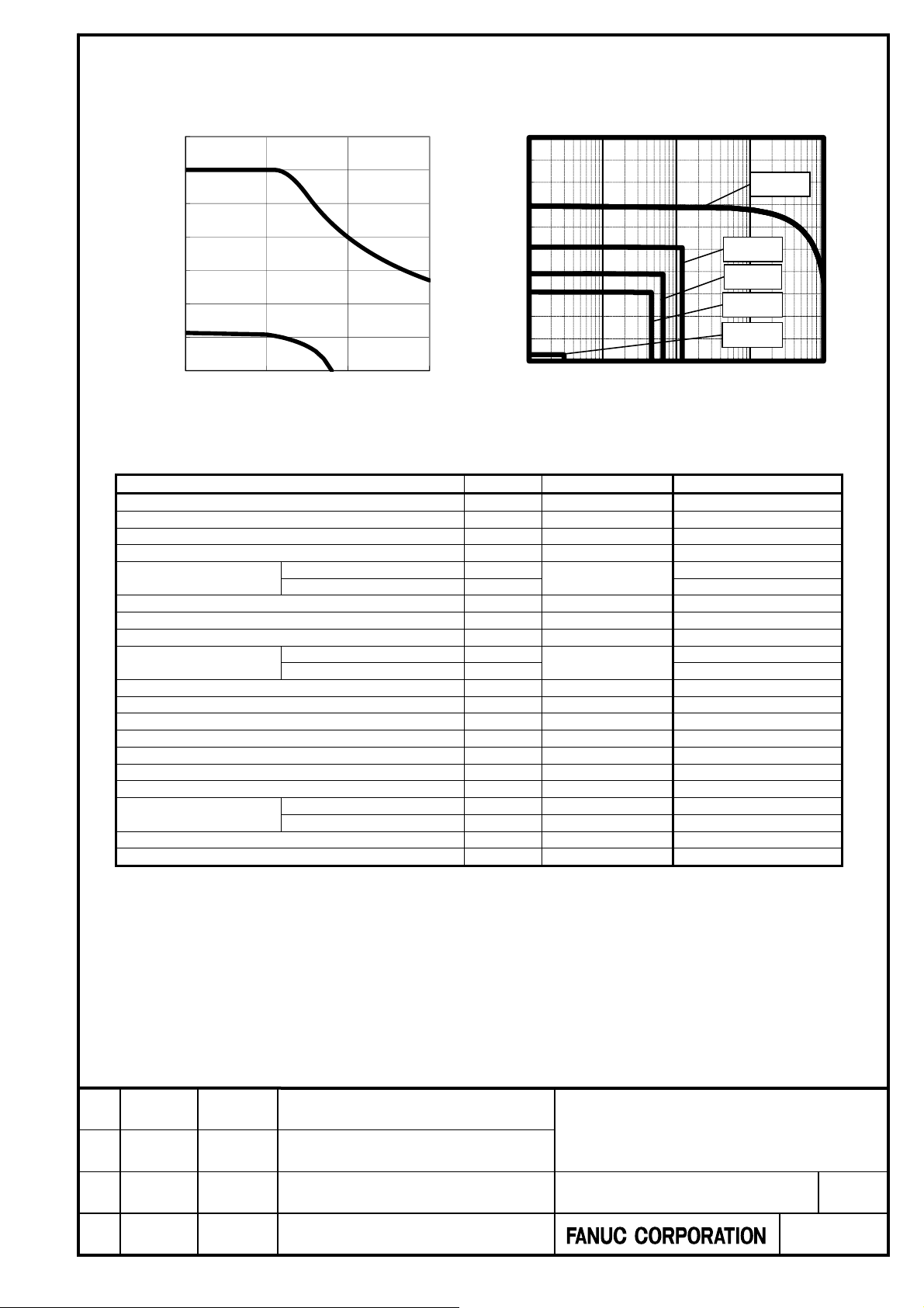
DiS 600/600-B (A06B-2331-B440) 400V no cooling
Torque-speed graph Overload duty characteristic
1400
1200
1000
800
Intermittent operation
600
Torque(Nm)
400
200
Continuous operation
0
0 200 400 600
Speed(min-1)
Specifications
Items Symbol Unit Specification
Input power voltage - V 400
Rated output (*) Pr kW 5.0
Rated torque (*) Tr Nm 184
Rated speed Nr min
Continuous torque (*)
Maximum torque (*) T
Upper speed for the maximum torque - min
Maximum speed N
Continuous current (*)
Maximum current I
Torque constant(*) Kt Nm/Arms 13.3
Winding resistance (between terminals) (*) Ra Ω 0.71
Thermal time constant tt min. 150
Required cooling capacity - W -
Flow rate Q L/min. -
Moment of inertia of rotor Jm kgm2 0.14
Mass
Number of poles P Pole 42
Maximum current of the applicable amplifier - Ap 180
(*): Indicates the standard value at a temperature of 20C. (10%)
The values may vary depending on the ambient temperature, series and edition of servo software, parameters,
input power supply voltage, servo amplifier specifications, individual motor difference, and others.
The values are subject to change without notice.
The overload duty characteristic is calculated based on the thermal characteristic of the running motor. The on
time may become shorter at 0 [min
At low speed Tc
At a stop Ts 226
At low speed Ic
At a stop Is 18.9
Stator Ws kg 24
Rotor Wr kg 11
-1
].
100%
90%
80%
70%
60%
duty [%]
50%
40%
30%
20%
10%
140%
160%
180%
MAX
0%
1 10 100 1000 10000
ON time [sec]
-
260
Nm
Nm 1200
ma
min
ma
Arms 113
ma
-
220
-
600
Arms
18.9
120%
226
Title.
FANUC CYNCHRONOUS BUILT-IN
01 18.01.26 Y.Sugimoto Newly Designed Senoo
Edit Date Design Description
SERVO MOTOR DiS-B series
DESCRIPTIONS
Draw.No..
-90200-0220EN/01
CUST.
Sheet.
12/29
Page 13

A
1.2 External Dimensions
DiS 180/800-B (A06B-2323-B330)
[Stator dimensions]
[Rotor dimensions]
Detail of A : Cable output area
(
=
A
O
2
2
0
1
5
°
3
0
°
5
R
1
2
.
(
=
3
6
0
2
5
.
7
1
3
4
6
0
v
/
1
4
8
v
°
)
30
O
1
4
6
5
7
°
/
2
8
)
12-M6
Depth13
(both sides)
9
2
R
5
(* Width of 9mm from the top)
28-M6 Depth9
B
164.5min. O
1
C
70
(Groove)
C
1
120 ±0.2
Detail of B : Groove for O-ring
0
87.5
-1
9
1
C
(*)
129O
230O
184.8
Title.
FANUC CYNCHRONOUS BUILT-IN
01 18.01.26 Y.Sugimoto Newly Designed Senoo
Edit Date Design Description
SERVO MOTOR DiS-B series
DESCRIPTIONS
Draw.No..
-90200-0220EN/01
CUST.
Sheet.
13/29
Page 14
A
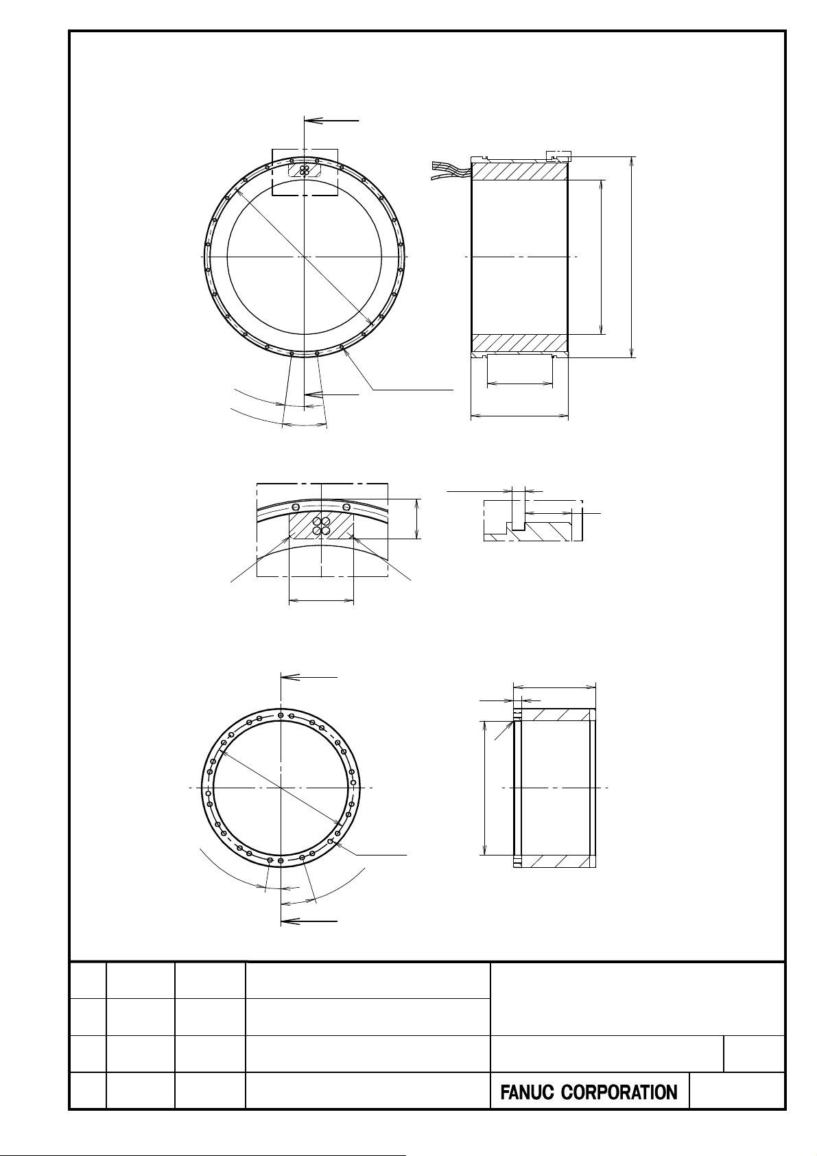
DiS 600/600-B (A06B-2331-B440)
[Stator dimensions]
[Rotor dimensions]
8
(
=
3
.
5
6
0
A
7
.
5
°
1
5
°
Detail of A : Cable output area
5
R
50
O
2
1
7
1
°
v
/
4
2
)
O
7
.
7
1
(
3
=
0
1
3
0
°
3
4
/
v
0
6
24-M6
Depth13
(both sides)
R
5
28-M8
Depth12
)
1
2
31
B
100
(Groove)
150 ±0.2
Detail of B : Groove for O-ring
4.8
0
-1
12
(*)
200O
(* Width of 12mm from the top)
122.5
1
C
18
238.5min. O
310O
Title.
FANUC CYNCHRONOUS BUILT-IN
01 18.01.26 Y.Sugimoto Newly Designed Senoo
Edit Date Design Description
SERVO MOTOR DiS-B series
DESCRIPTIONS
Draw.No..
-90200-0220EN/01
CUST.
Sheet.
14/29
Page 15
A
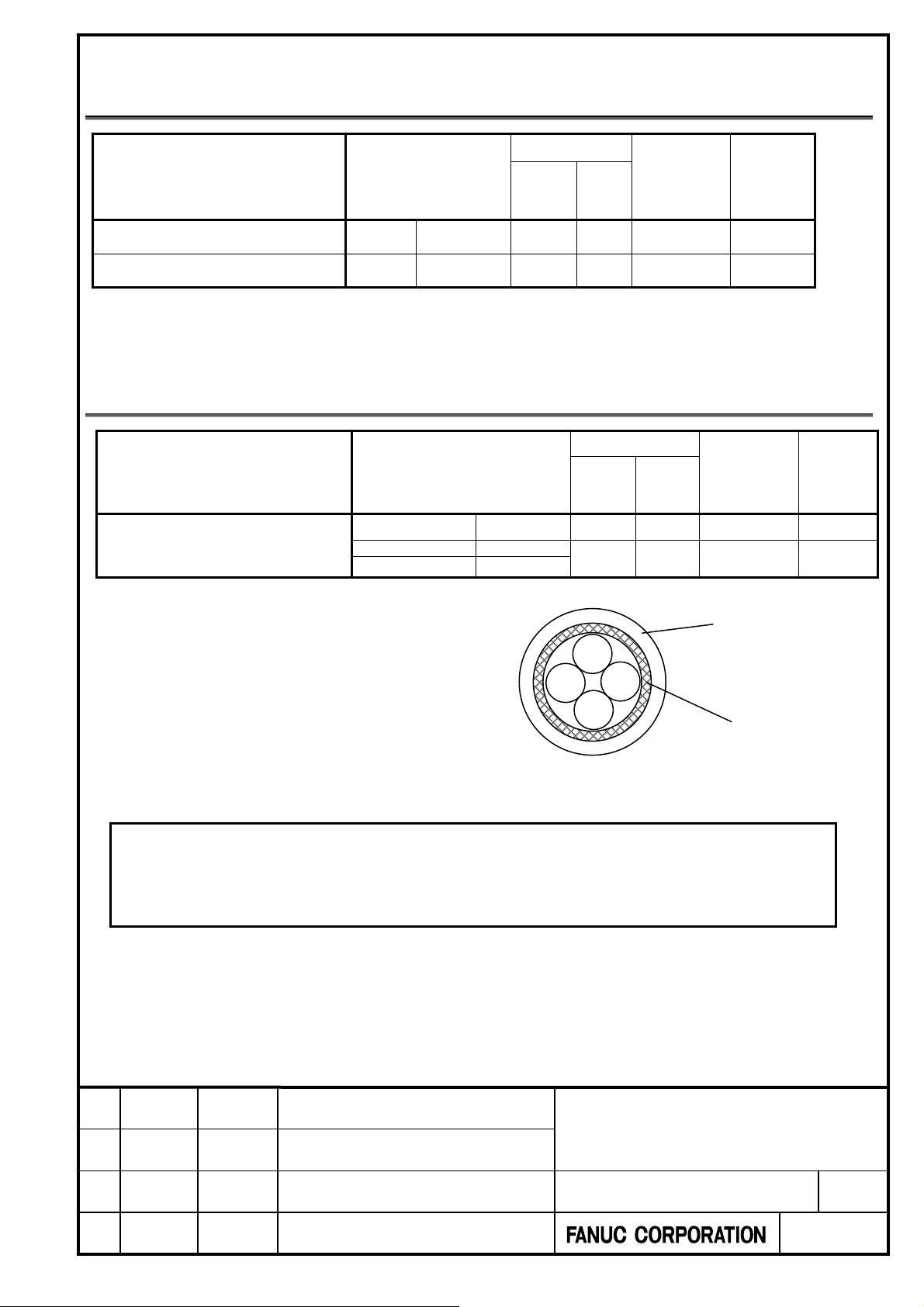
1.3 Specifications of Power Lines
Conductor size
Model (Ordering number) Color
DiS 180/800-B (A06B-2323-B330)
DiS 600/600-B (A06B-2331-B440)
Power lines are about 2 m long.
No ground lead is supplied with any motor. For how to select and connect ground leads, see FANUC SYNCHRONOUS
BUILT-IN SERVO MOTOR DiS-B series DESCRIPTIONS (B-65492EN) or FANUC SYNCHRONOUS BUILT-IN
SERVO MOTOR DiS series DESCRIPTIONS (B-65332EN).
U,V,W
U,V,W
Red, white,
black
Red, white,
black
Cross-
section
(mm
2 14
5.5 10
AWG
size
2
)
Outer
diameter
(mm)
3.1 to 3.4
4.3 to 4.6
Minimum
bending
radius
(mm)
16.0
21.0
1.4 Specifications of Thermistor Cable
Conductor size
Model (Ordering number) Color
DiS 180/800-B (A06B-2323-B330)
DiS 600/600-B (A06B-2331-B440)
Thermistor cable is about 2 m long.
Sheath Black - -
PTC thermistor Red / White
NTC thermistor Blue / Brown
Cross-
section
(mm
0.2 24
AWG
size
2
)
diameter
4.3 to 5.0
Brown
Red
White
Blue
Note
These motors described in this manual have a PTC thermistor and can use only iCZ sensor, Synchronous
Built-in Servo Motor Position Detection Circuit and Temperature Detection Circuit which can apply a PTC
thermistor. For details, refer to B-65492EN "5.1 Absolute iCZ Sensor (for Synchronous Built-in Servo Motor)",
"5.2 Synchronous Built-in Servo Motor Position Detection Circuit", " Appendix C Temperature Detection Circuit ","
Appendix D Temperature Detection Circuit (External Contact Output Type) ".
Outer
(mm)
1.2
Sheath
Braided shield
Minimum
bending
radius
(mm)
22.5
6.0
Title.
FANUC CYNCHRONOUS BUILT-IN
01 18.01.26 Y.Sugimoto Newly Designed Senoo
Edit Date Design Description
SERVO MOTOR DiS-B series
DESCRIPTIONS
Draw.No..
-90200-0220EN/01
CUST.
Sheet.
15/29
Page 16
A
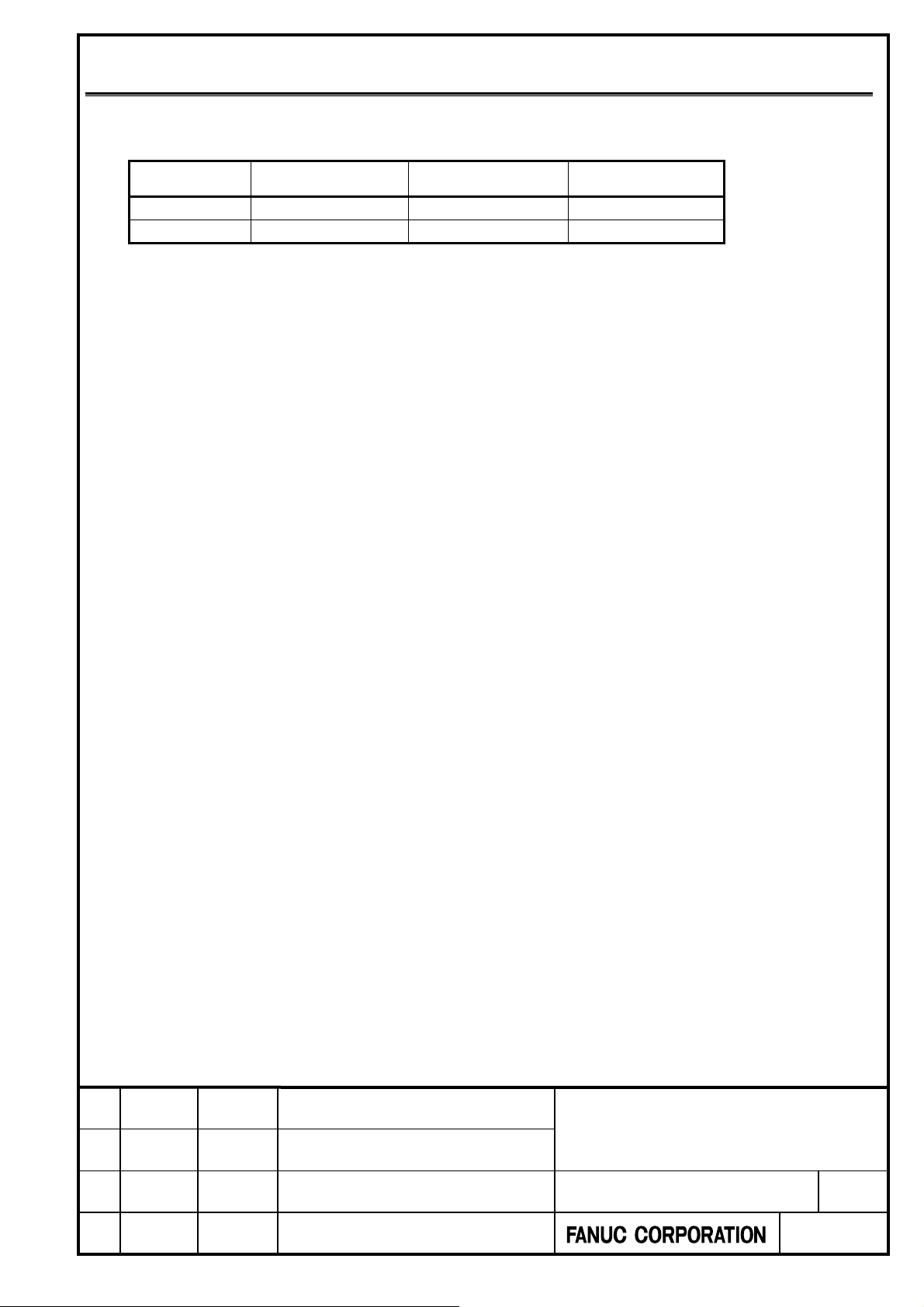
1.5 Stator and Rotor Specifications
A stator or rotor can be supplied singly as a maintenance part.
The following table lists the stator and rotor ordering number corresponding to each model.
Model
DiS 180/800-B
DiS 600/600-B
Motor
Ordering number
A06B-2323-B330 A290-3323-T430 A290-3323-T530
A06B-2331-B440 A290-3331-T440 A290-3331-T540
Stator
Ordering number
Rotor
Ordering number
Title.
FANUC CYNCHRONOUS BUILT-IN
01 18.01.26 Y.Sugimoto Newly Designed Senoo
Edit Date Design Description
SERVO MOTOR DiS-B series
DESCRIPTIONS
Draw.No..
-90200-0220EN/01
CUST.
Sheet.
16/29
Page 17
A
2 SYSTEM CONFIGURATIONS AND
SELECTION
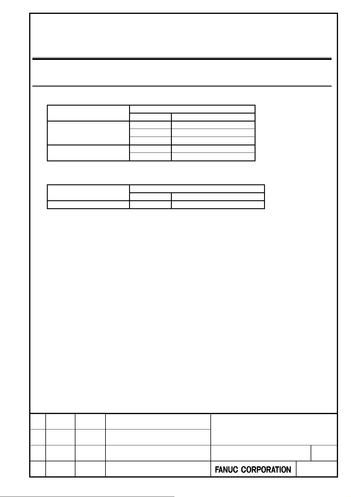
2.1 CNCs and applicable series and editions of servo software
CNCs and applicable series and editions of servo software for driving a motor described in this manual are as follows:
CNC
Series 30i/31i/32i/35i-B
Power Motion i-A
DSA-B
Series 0i-F
Series Edition
90J0 05.0 and subsequent editions
90K0 05.0 and subsequent editions
90JP 02.0 and subsequent editions
90M0 04.0 and subsequent editions
90M8 04.0 and subsequent editions
However, as of December 2017, Smoothing Compensation can be used only under the following conditions. Regarding
other CNCs and rotary encoders, Smoothing Compensation will become applicable in the future.
CNC
Series 30i/31i/32i/35i-B
Rotary encoder : the resolution per revolution is represented by a 2n (binary number) and that supports the FANUC
serial interface.
Series Series
90J0 11.0 and subsequent editions
Servo software
Servo software
Title.
FANUC CYNCHRONOUS BUILT-IN
01 18.01.26 Y.Sugimoto Newly Designed Senoo
Edit Date Design Description
SERVO MOTOR DiS-B series
DESCRIPTIONS
Draw.No..
-90200-0220EN/01
CUST.
Sheet.
17/29
Page 18
A
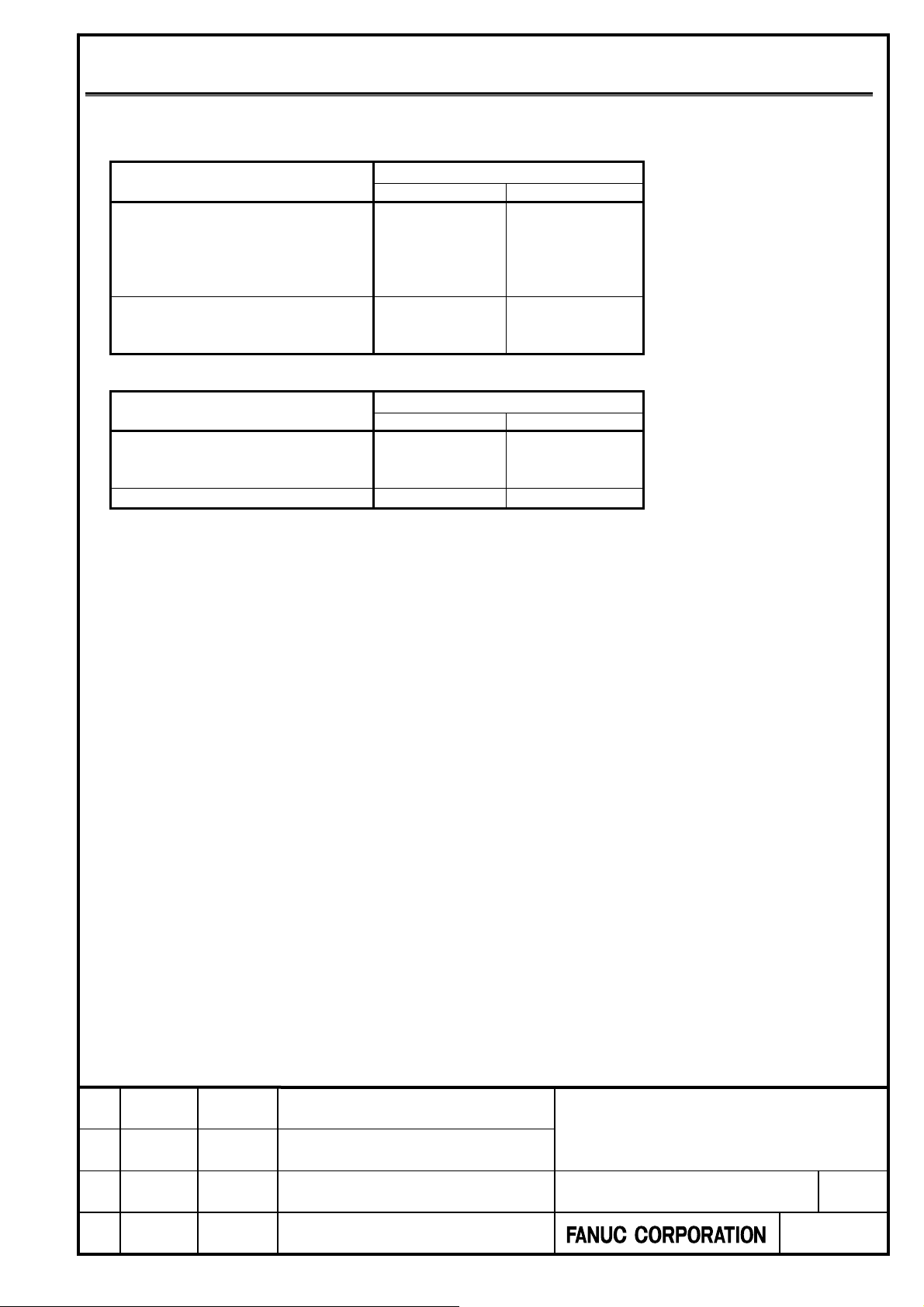
2.2 Applicable servo amplifier specifications
The following table lists applicable amplifiers in Servo Amplifier i-B series
Input power voltage : 200V
Model (Ordering number)
iSV 80-B
iSV 40/80-B
DiS 180/800-B (A06B-2323-B330)
DiS 600/600-B (A06B-2331-B440)
iSV 80/80-B
iSV 80/160-B
iSV 80/80/80-B
iSV 160-B
iSV 80/160-B
iSV 160/160-B
Input power voltage : 400V
Model (Ordering number)
iSV 80HV-B
DiS 180/800-B (A06B-2323-B330)
DiS 600/600-B (A06B-2331-B440)
iSV 40/80HV-B
iSV 80/80HV-B
iSV 180HV-B
The Servo Amplifier i-B series is applicable in the same way as the Servo Amplifier i-B series. However, when the
Servo Amplifier i-B series is used, driving conditions and functions that can be used with the Servo Amplifier i-B
series may be restricted. be sure to contact FANUC before using the i-B series.
Applicable amplifiers
Name Ordering number
A06B-6240-H125
A06B-6240-H208
A06B-6240-H209
A06B-6240-H210
A06B-6240-H331
A06B-6240-H126
A06B-6240-H210
A06B-6240-H211
Applicable amplifiers
Name Ordering number
A06B-6290-H125
A06B-6290-H208
A06B-6290-H209
A06B-6290-H126
Title.
FANUC CYNCHRONOUS BUILT-IN
01 18.01.26 Y.Sugimoto Newly Designed Senoo
Edit Date Design Description
SERVO MOTOR DiS-B series
DESCRIPTIONS
Draw.No..
-90200-0220EN/01
CUST.
Sheet.
18/29
Page 19
A
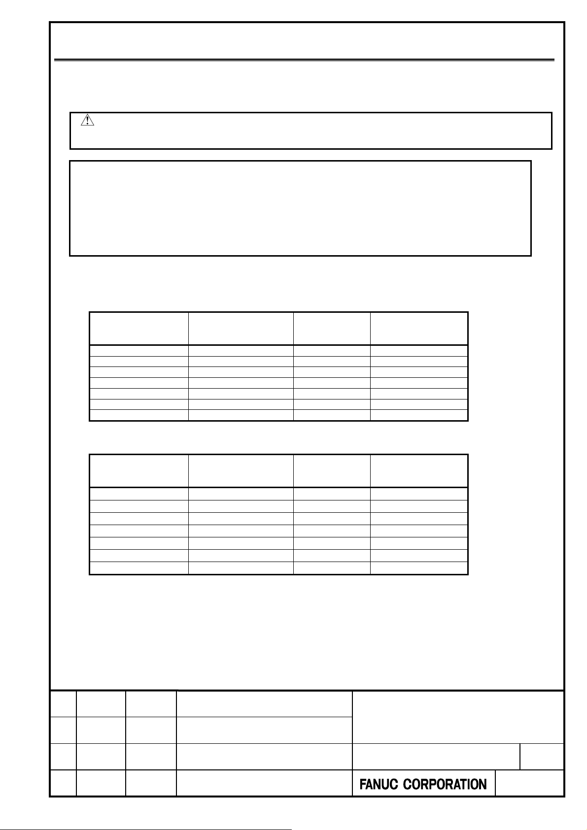
2.3 Load moment of inertia
The maximum load moment of inertia is limited according to the capacities of the servo amplifier and dynamic brake
module (DBM) and momentum energy of the axis.
Limit maximum motor speed for each load moment of inertia according to the table below and set the over speed alarm
(parameter No. 2052) to the value shown in the table below.
CAUTION
If it is used exceeding the maximum rotation speed indicated in the table, there is a possibility of damaging the servo
amplifier and DBM. Be sure to set an appropriate over speed alarm.
NOTE
1 The maximum load moment of inertia does not include the moment of inertia of rotor.
2 The maximum load moment of inertia is limited according to the capacities of the servo amplifier and DBM.
Controllability is not guaranteed even when the load moment of inertia does not exceed the maximum load
moment of inertia. When the load moment of inertia is large, if the rigidity of the connection between the motor
and load is low, vibration may be caused.
3 Note that the maximum load moment of inertia varies depending on the servo amplifier and DBM specifications
for some models.
4 If you want to use the Servo Amplifier i-B series, be sure to contact FANUC.
DiS 180/800-B (A06B-2323-B330)
Input power voltage: 200V
Maximum load
moment of inertia
[kgm
0-8.8 0-330 400 460
8.8-11 330-420 350 420
11-15 420-570 300 360
15-22 570-840 250 300
22-35 840-1300 200(*) 240(*)
35-63 1300-2400 150 180
63-140 2400-5300 100 120
*) Initial setting value
Input power voltage: 400V
Maximum load
moment of inertia
[kgm
0-0.9 0-34 800 960
0.9-1.2 34-46 700 840
1.2-1.7 46-65 600 720
1.7-2.5 65-96 500 600
2.5-3.9 96-150 400(*) 480(*)
3.9-7 150-260 300 360
7-15 260-570 200 240
*) Initial setting value
Maximum load
2
]
2
]
moment of inertia
ratio
Maximum load
moment of inertia
ratio
Maximum
motor speed
motor speed
-1
]
[min
Maximum
-1
]
[min
Over Speed alarm
(No.2052)
Upper limit value
Over Speed alarm
(No.2052)
Upper limit value
Title.
FANUC CYNCHRONOUS BUILT-IN
01 18.01.26 Y.Sugimoto Newly Designed Senoo
Edit Date Design Description
SERVO MOTOR DiS-B series
DESCRIPTIONS
Draw.No..
-90200-0220EN/01
CUST.
Sheet.
19/29
Page 20
A
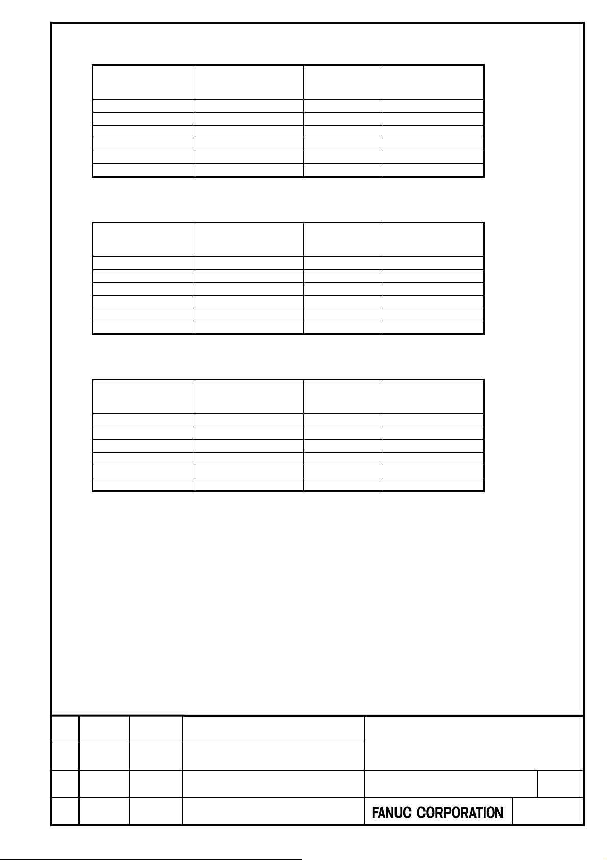
DiS 600/600-B (A06B-2331-B440)
Input power voltage: 200V
Maximum load
moment of inertia
[kgm
2
]
0-26 0-180 300 340
26-38 180-270 250 300
38-60 270-420 200 240
60-100 420-710 150(*) 180(*)
100-240 710-1700 100 120
240-960 1700-6800 50 60
*) Initial setting value
Input power voltage: 400V
Applicable DBM specifications : A06B-6069-H300, H301
Maximum load
moment of inertia
[kgm
2
]
0-57 0-400 600 720
57-82 400-580 500 600
82-120 580-850 400 480
120-220 850-1500 300(*) 360(*)
220-510 1500-3600 200 240
510-2000 3600-14000 100 120
*) Initial setting value
Input power voltage: 400V
Applicable DBM specifications : A06B-6079-H401, H403
Maximum load
moment of inertia
[kgm
2
]
0-19 0-130 600 720
19-27 130-190 500 600
27-43 190-300 400 480
43-77 300-550 300(*) 360(*)
77-170 550-1200 200 240
170-690 1200-4900 100 120
*) Initial setting value
Maximum load
moment of inertia
ratio
Maximum load
moment of inertia
ratio
Maximum load
moment of inertia
ratio
Maximum
motor speed
[min
-1
]
Maximum
motor speed
[min
-1
]
Maximum
motor speed
[min
-1
]
Over Speed alarm
(No.2052)
Upper limit value
Over Speed alarm
(No.2052)
Upper limit value
Over Speed alarm
(No.2052)
Upper limit value
Title.
FANUC CYNCHRONOUS BUILT-IN
01 18.01.26 Y.Sugimoto Newly Designed Senoo
Edit Date Design Description
SERVO MOTOR DiS-B series
DESCRIPTIONS
Draw.No..
-90200-0220EN/01
CUST.
Sheet.
20/29
Page 21
A
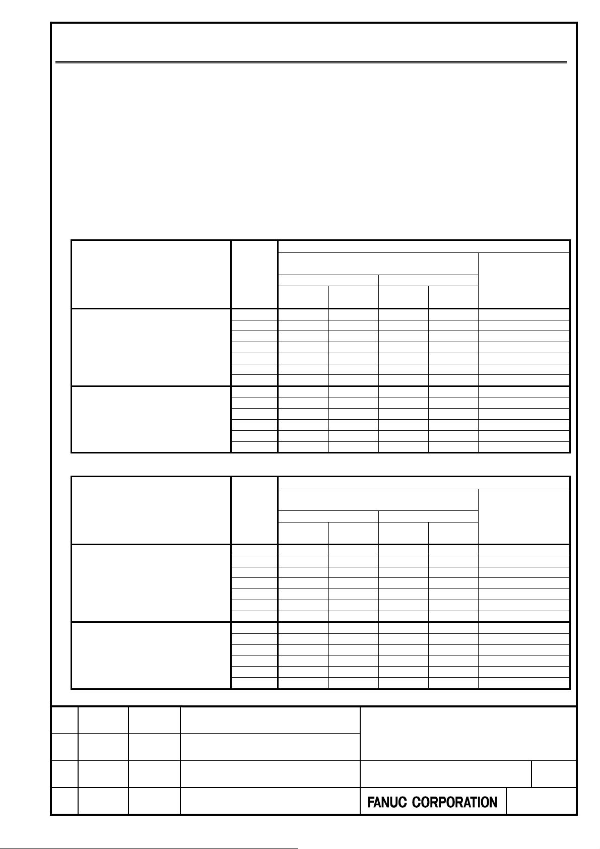
2.4 Data for iPS-B (POWER SUPPLY) selection
CAUTION
Data for iPS-B (POWER SUPPLY) selection on this report is applied only in case of FANUC SERVO
AMPLIFIER i-B series.
When FANUC SERVO AMPLIFIER βi-B series is used, driving conditions and functions that can be used with
SERVO AMPLIFIER i-B series may be restricted. Please be sure to contact FANUC before using FANUC SERVO
AMPLIFIER βi-B series.
Data for iPS-B (POWER SUPPLY) selection is prepared by applicable condition and cooling method.
Condition 1: Axis of tilt and rotation for machining center, Axis of work rotation for hobbing machine and grinding
machine.
Condition 2: Otherwise Applicable condition 1 (Asis of lathe for combined machining machine, Axis of press for press
machine, Axis of oscillation for cam grinding mashine, etc.)
(1) Input power voltage: 200V
Data for iPS-B selection
Motor
Model (Ordering number)
DiS 180/800-B (A06B-2323-B330)
DiS 600/600-B (A06B-2331-B440)
(2) Input power voltage: 400V
Model (Ordering number)
DiS 180/800-B (A06B-2323-B330)
DiS 600/600-B (A06B-2331-B440)
Speed
-1
]
[min
Cooling
100 2.1 0.6 3.5 0.9 11.7
150 2.5 0.8 4.1 1.3 11.7
200 2.6 0.9 4.2 1.4 11.7
250 2.6 - 4.2 - 11.7
300 2.6 - 4.2 - 11.7
350 2.6 - 4.2 - 11.7
400 2.6 - 4.2 - 11.7
50 3.0 0.8 5.0 1.3 16.5
100 4.3 1.5 7.1 2.4 21.6
150 5.3 2.1 8.8 3.5 21.6
200 5.3 - 8.8 - 21.6
250 5.3 - 8.8 - 21.6
300 5.3 - 8.8 - 21.6
Motor
Speed
-1
]
[min
Cooling
200 3.0 1.1 4.9 1.7 15.4
300 3.9 1.4 6.4 2.3 18.7
400 4.7 1.5 7.8 2.4 18.7
500 5.1 - 8.4 - 18.7
600 5.1 - 8.4 - 18.7
700 5.1 - 8.5 - 18.7
800 5.1 - 8.5 - 18.7
100 4.9 1.5 8.1 2.4 21.7
200 7.7 2.6 12.8 4.2 32.1
300 11.3 2.6 18.7 4.7 35.6
400 12.6 - 20.9 - 35.6
500 12.6 - 20.9 - 35.6
600 12.6 - 20.9 - 35.6
01 18.01.26 Y.Sugimoto Newly Designed Senoo
Edit Date Design Description
Continuous rated output
[kW]
Condition 1 Condition 2
Oil
Condition 1 Condition 2
Oil
No
Cooling
Continuous rated output
No
Cooling
Title.
Oil
Cooling
Data for iPS-B selection
[kW]
Oil
Cooling
FANUC CYNCHRONOUS BUILT-IN
SERVO MOTOR DiS-B series
DESCRIPTIONS
Draw.No..
-90200-0220EN/01
No
Cooling
No
Cooling
Maximum output
at acceleration
[kW]
Maximum output
at acceleration
[kW]
Sheet.
CUST.
21/29
Page 22

A
3 MOTOR HANDLING, MECHANICAL DESIGN,
AND MOTOR INSTALLATION
3.1 MOTOR HANDLING
WARNING
1 Mishandling a Synchronous Built-in Servo Motor DiS-B series motor may be highly
dangerous, resulting in a fatal accident. Read this section thoroughly and
understand it first and then strictly observe the notes. Do not handle Synchronous
Built-in Servo Motor DiS-B series motors unless you have been trained in handling
them.
2 A rotor uses a large number of very strong magnets. It may cause a malfunction of
a medical apparatus such as a pacemaker or ICD. For this reason, any person
having a medical apparatus must keep away from the rotor. Also arrange an
environment to keep any person having a medical apparatus away from the rotor.
Such a person must keep at least 30 cm away from the rotor when it is absolutely
necessary for him or her to approach the rotor.
3 When touching the cooling grooves of the stator and the rotor (including the
attached tinplate), we ask for countermeasures such as using thick gloves and
handling carefully in order to prevent tearing and pinching by magnetic attraction
force.
Title.
01 18.01.26 Y.Sugimoto Newly Designed Senoo
Edit Date Design Description
FANUC CYNCHRONOUS BUILT-IN
SERVO MOTOR DiS-B series
DESCRIPTIONS
Draw.No..
-90200-0220EN/01
Sheet.
CUST.
22/29
Page 23
A
3.2 MECHANICAL DESIGN
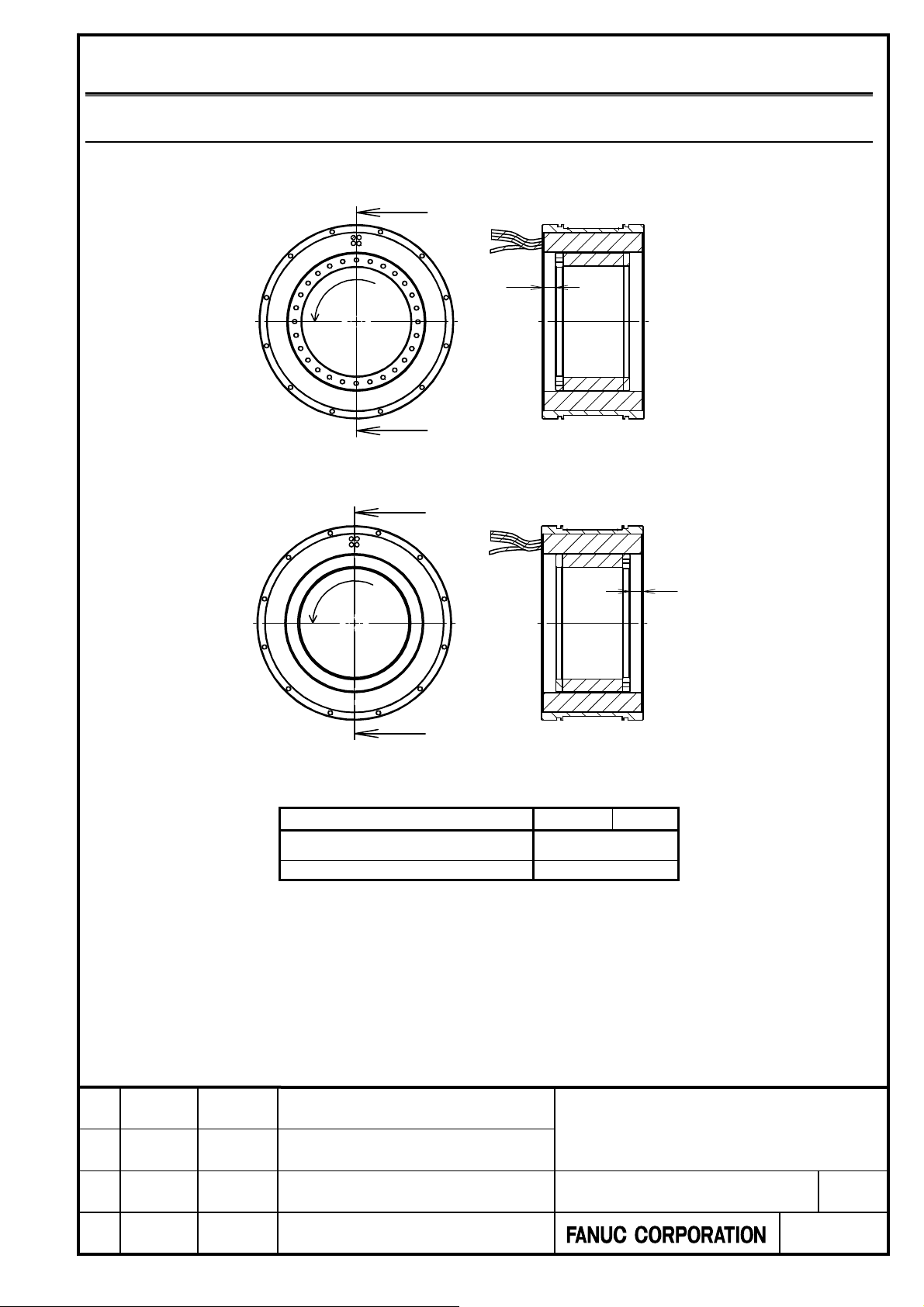
3.2.1 Rotor Installation Direction
The rotor has an asymmetrical top and bottom shape, and the fixing screw hole is provided only on one end face.
The stator can be installed in any direction shown in the following figure.
Positive
direction of
motor rotation
Positive
direction of
motor rotation
Model (Ordering number)
DiS 180/800-B (A06B-2323-B330)
DiS 600/600-B (A06B-2331-B440)
X
Y
X Y
15.5±1
12.5±1
Title.
FANUC CYNCHRONOUS BUILT-IN
01 18.01.26 Y.Sugimoto Newly Designed Senoo
Edit Date Design Description
SERVO MOTOR DiS-B series
DESCRIPTIONS
Draw.No..
-90200-0220EN/01
CUST.
Sheet.
23/29
Page 24

A
3.2.2 Desigining Rotor Fixing Thread Section
Please use all screw holes on the end surface of the rotor and fix it with bolts of strength class 10.9 or higher.
Design the rotor fixing part so that the screw length is shorter than the sum of the through hole (A) of the rotor fixing part and
rotor thread depth (B) shown in the figure below, and do not tighten the screw beyond the rotor thread depth.
Note
Tightening the screw beyond the rotor thread depth may damage the rotor.
Rotor fixing part
(A)
Through hole
Rotor thread depth
Model (Ordering number)
DiS 180/800-B (A06B-2323-B330)
DiS 600/600-B (A06B-2331-B440)
(B)
Bolt size B
M6 9
M8 12
Title.
FANUC CYNCHRONOUS BUILT-IN
01 18.01.26 Y.Sugimoto Newly Designed Senoo
Edit Date Design Description
SERVO MOTOR DiS-B series
DESCRIPTIONS
Draw.No..
-90200-0220EN/01
CUST.
Sheet.
24/29
Page 25
A
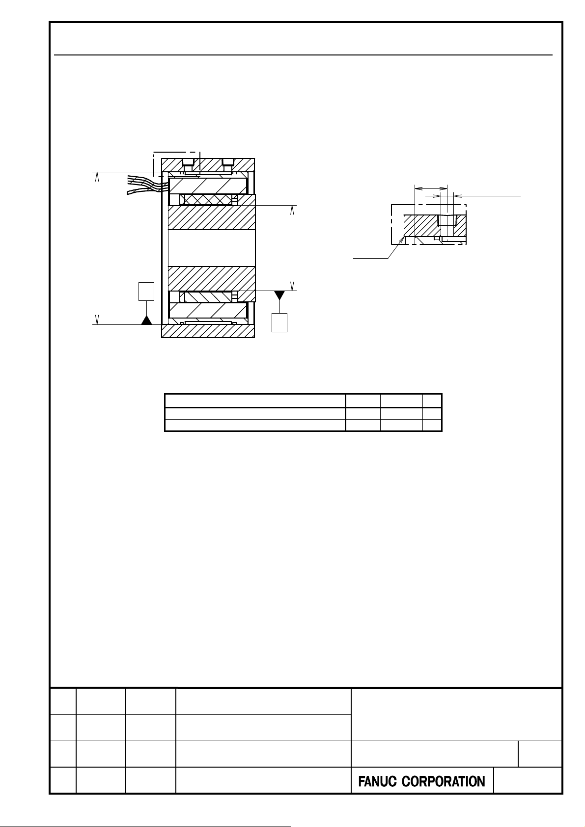
3.2.3 Designing the Motor Engagement Region
The dimensions of a stator engagement region and a rotor engagement region must be as given in the table below. If
liquid cooling is to be used, the dimensions of the coolant inlet must be as given in the table below. (Design the coolant
outlet in the same way as that for the coolant inlet.)
The eccentricity of sides A and B in relation to the rotation center must be 0.01 mm or less.
*) Sides A and B are not motor’s surfaces but machine’s surfaces.
C
OD
(The diameter to fit the stator)
C
A
A
Model (Ordering number)
DiS 180/800-B (A06B-2323-B330)
DiS 600/600-B (A06B-2331-B440)
B
B
Od
(The diameter to fit the rotor)
Detail of C: Coolant In
Z
Z
Chamfer
d D Z
129 f7 230 H8 30
200 f7 310 H8 30
12max. O
Title.
FANUC CYNCHRONOUS BUILT-IN
01 18.01.26 Y.Sugimoto Newly Designed Senoo
Edit Date Design Description
SERVO MOTOR DiS-B series
DESCRIPTIONS
Draw.No..
-90200-0220EN/01
CUST.
Sheet.
25/29
Page 26

A
Even if the fitting part is designed according to the table on the previous page, the rotor and the stator may collide with
each other until the rotor end surface is fixed.
Please design first to fix the rotor end face and install it by either of the following methods.
1. Insert stator afterward
2. Provide a part to guide concentricity
First to fix
the rotor end face
Case 1 Case 2
Insert stator
afterward
First to fix
the rotor end face
Stator
Rotor
Guide concentricity
with a guide part
Title.
FANUC CYNCHRONOUS BUILT-IN
01 18.01.26 Y.Sugimoto Newly Designed Senoo
Edit Date Design Description
SERVO MOTOR DiS-B series
DESCRIPTIONS
Draw.No..
-90200-0220EN/01
CUST.
Sheet.
26/29
Page 27

A
3.2.4 O-Ring for Cooling Jacket
For use in liquid cooling, two O-rings are required per motor. Use the O-ring grooves of the stator to attach O-rings.
O-rings are not supplied with the motors, so the customer is requested to prepare them.
Applicable O-rings are given in the table below. Applicable O-rings may be purchased from FANUC.
Model (Ordering number) Applicable O-ring O-ring Ordering number
AS568 O-ring for airplane
DiS 180/800-B (A06B-2323-B330)
DiS 600/600-B (A06B-2331-B440)
Bearing number: 269
Material: Type 4 D
AS568 O-ring for airplane
Bearing number: 278
Material: Type 4 D
A06B-0494-K002
A06B-0495-K002
Title.
FANUC CYNCHRONOUS BUILT-IN
01 18.01.26 Y.Sugimoto Newly Designed Senoo
Edit Date Design Description
SERVO MOTOR DiS-B series
DESCRIPTIONS
Draw.No..
-90200-0220EN/01
CUST.
Sheet.
27/29
Page 28

A
4 Parameters
DiS 180/800-B (A06B-2323-B330)
These parameters are for HRV2 and applied for liquid cooling operation.
PRM NO SERVO PRM.
2003 00001000 00001000 2067 T CMD FILTER 0 0
2004 10000011 10000011 2068-2073 0 0
2005 00000000 00000000 2074 AALPH 0 0
2006 00001010 00001010 2077-2083 0 0
2007 00000000 00000000 2086 RATED CURRENT 995 995
2008 00000000 00000000 2087-2089 0 0
2009 00100000 00100000 2090 ROBSTL 0 0
2010 00000001 00000001 2091-2098 0 0
2011 00000000 00000000 2099 ONEPSL 400 400
2012 00000000 00000000 2100 INPA1 0 0
2013 00000100 00000100 2101 INPA2 0 0
2014 00000100 00000100 2102 DB LIM 0 0
2210 00000000 00000000 2103 ABVOF 0 0
2211 00010000 00010010 2104 ABTSH 0 0
2300 10000101 10000101 2105 TO RQUE C ONST. 7612 7612
2301 01000110 01000110 2106-2109 0 0
2560 01100011 01000001 2110 MGSTCM 1809 1809
2040 CUR GAIN I 3000 5000 2111 TQLIM IN DEC. 5404 16650
2041 CUR GAIN P -27000 -15200 2112 AMRDML 0 0
2042 CUR GAIN 3 -3139 -3139 2113 HRV FILT 0 0
2043 VEL GAIN I 120 120 2127 NINTCT 0 0
2044 VEL GAIN P - 1079 -1079 2128 MFWKCE 300 400
2045 VEL GAIIN 3 0 0 2129 MFWKB L 5382 15367
2046 VEL GAIN4 -8235 - 8235 2130-2132 SMOOTH CMP 0 0
2047 OBSERVER POA1 7818 7818 2133 PHDLY1 2760 8242
2048 BLACC CMP 0 0 2134 PHDLY2 15360 7695
2049 DPFMX 0 0 2159 DGCSMM 7700 13641
2050 OBSERVER POK1 956 956 2160 TRQCUP 5190 5190
2051 OBSERVER POK2 510 510 2161 OVC STP 0 0
2052 OVER SPEED 240 480 2162 O VC2 K1 0 0
2053 DB-CMP PPMAX 21 21 2163 OVC2 K2 0 0
2054 D B-CMP PDDP 1894 1894 2164 OVC2 LIMIT 0 0
2055 DB-C MP PHYST 319 319 2165 MAX CURRENT 85 85
2056 E MFCMP 0 0 2302 TQLIM AT STOP 0 0
2057 D-PHASE CUR -7694 -12805 2304 ACCB SLM 0 0
2058 D-PHASE CUR -2360 -2150 2305 ACDCEBD 81 190
2059 PPBAS 0 0 2310 DC IDBS 0 0
2060 TCMD LIMIT 6554 6554 2316 LIMLIM 0 0
2061 EMFLMT 0 0 2574 VELOVC 0 0
2062 OVC K1 32714 32714 2576 0 0
2063 OVC K2 674 674 2580 0 0
2064 TGALMLV 4 4 2590 8000 5600
2065 OVC LIMIT 1580 1580 2591 -16000 -20800
2066 ACC FB GAIN 0 0 2595 1113 1318
Please set parameters for a rotary encoder according to "Parameter Manual (B-65270EN/09)”.
The number of poles of this motor is 28.
Set 418 as motor ID number. As parameters of the motor is not loaded automatically, it is necessary to set the
parameters according to the table.
Motor speed is limited to a small value by the parameters. Change a parameter according to “2.3 Load moment of
inertia”.
In the case of liquid cooling operation, please set the parameters on the following table.
200V
NC
PRM NO SERVO PRM.
2062 POVC1 32465 32465
2063 POVC2 3786 3786
2065 POVCLMT 7967 7967
2086 RTCURR 2340 2340
2161 OVCSTP 127 127
400V
NC
PRM NO SERVO PRM.
200V
Oil cooling
400V
Oil cooling
200V
NC
400V
NC
*NC stands for no cooling.
Title.
FANUC CYNCHRONOUS BUILT-IN
01 18.01.26 Y.Sugimoto Newly Designed Senoo
Edit Date Design Description
SERVO MOTOR DiS-B series
DESCRIPTIONS
Draw.No..
-90200-0220EN/01
CUST.
Sheet.
28/29
Page 29

A
iS 600/600-B (A06B-2331-B440)
D
These parameters are for HRV2 and applied for liquid cooling operation.
PRM NO SERVO PRM.
2003 00001000 00001000 2067 TCMD FILTER 0 0
2004 10000011 10000011 2068-2073 0 0
2005 00000000 00000000 2074 AALPH 0 0
2006 00001010 00001010 2077-2083 0 0
2007 00000000 00000000 2086 RATED C URRENT 1097 975
2008 00000000 00000000 2087-2089 0 0
2009 00100000 00100000 2090 ROBS TL 0 0
2010 00000001 00000001 2091-2098 0 0
2011 00000000 00000000 2099 ONEPSL 400 400
2012 00000000 00000000 2100 INPA1 0 0
2013 00000010 00000010 2101 INPA2 0 0
2014 00000010 00100010 2102 DBLIM 0 0
2210 00000000 00000000 2103 ABVOF 0 0
2211 00010010 00010010 2104 ABTSH 0 0
2300 10000101 10000101 2105 TO RQUE CONST. 20663 20663
2301 01000110 01000110 2106-2109 0 0
2560 01100011 01100001 2110 MGSTCM 1809 2065
2040 CUR GAIN I 2750 1270 2111 TQ LIM IN DEC. 6182 13585
2041 CUR GAIN P -23800 -10800 2112 AMRDML 0 0
2042 CUR GAIN 3 -3162 - 3162 2113 HRV FILT 0 0
2043 VEL GAIN I 234 234 2127 NINTCT 0 0
2044 VEL GAIN P -2094 -2094 2128 MFWKCE 1500 800
2045 VEL GAIIN 3 0 0 2129 MFWKBL 5128 10248
2046 VEL GAIN4 -8235 -8235 2130-2132 SMOOTH CMP 0 0
2047 OBSERVER POA1 4027 4027 2133 PHDLY1 2660 6244
2048 BLACC CMP 0 0 2134 PHDLY2 8965 8972
2049 DP FMX 0 0 2159 DGCSMM 5143 6945
2050 OBSERVER POK1 956 956 2160 TRQ CUP 5200 5200
2051 OBSERVER POK2 510 510 2161 O VC STP 0 0
2052 OVER SPEED 180 360 2162 OVC2 K1 0 0
2053 DB-CMP PPMAX 21 21 2163 OVC2 K2 0 0
2054 D B-CMP PDDP 1894 1894 2164 O VC2 LIMIT 0 0
2055 DB-C MP PHYST 319 319 2165 MAX CURRENT 165 185
2056 E MFCMP 0 0 2302 TQLIM AT STOP 0 0
2057 D-PHASE CUR -7188 -6917 2304 ACCBSLM 0 0
2058 D-PHASE CUR -2250 -2250 2305 ACDCEBD 80 130
2059 PPBAS 0 0 2310 DCIDBS 0 0
2060 TCMD LIMIT 7282 6473 2316 LIMLIM 0 0
2061 EMFLMT 0 0 2574 VELOVC 0 0
2062 OVC K1 32715 32715 2576 0 0
2063 OVC K2 666 666 2580 0 0
2064 TGALMLV 4 4 2590 4160 3840
2065 OVC LIMIT 1928 1523 2591 -10800 - 18200
2066 ACC FB GAIN 0 0 2595 1011 1315
200V
NC
400V
NC
PRM NO SERVO PRM.
200V
NC
400V
NC
*NC stands for no cooling.
Please set parameters for a rotary encoder according to "Parameter Manual (B-65270EN/09)”.
The number of poles of this motor is 42.
Set 418 as motor ID number. As parameters of the motor is not loaded automatically, it is necessary to set the
parameters according to the table.
Motor speed is limited to a small value by the parameters. Change a parameter according to “2.3 Load moment of
inertia”.
In the case of liquid cooling operation, please set the parameters on the following table.
PRM NO SERVO PRM.
200V
Oil cooling
2062 POVC1 32463 32352
2063 POVC2 3809 5203
2065 POVLMT 9887 10181
2086 RTCURR 2606 2646
2161 OVCSTP 105 120
400V
Oil cooling
Title.
FANUC CYNCHRONOUS BUILT-IN
01 18.01.26 Y.Sugimoto Newly Designed Senoo
Edit Date Design Description
SERVO MOTOR DiS-B series
DESCRIPTIONS
Draw.No..
-90200-0220EN/01
CUST.
Sheet.
29/29
 Loading...