

Page 1

ADDITIONAL INFORMATION
Page 2
FANUC Series 30i /31i /32i-A, 31i-A5
1. Type of applied technical documents
Name
FANUC Series 30i -MODEL A
FANUC Series 31
FANUC Series 32
Common to Lathe System / Machining Center System
USER’S MANUAL
Rate Feed function
i -MODEL A
i -MODEL A
Spec.No./Version
B-63944EN/03
2. Summary of change
Group Name / Outline New,
Basic
Function
Optional
Rate Feed function is added.
Function
Unit
Maintenance
parts
Applicable
Add,
Date
Correct,
Delete
Add Immediately
Notice This function is available in the following software.
G004, G014, G024, G034:11.0 edition or later
G124,G134:11.0 edition or later
G104,G114:11.0 edition or later
Correction
G204:11.0 edition or later
Another
Ed. Date Design Description
Date Design. Apprv.
Title
Draw
No.
FANUC Series 30i/31i/32i-A, 31i-A5
Rate Feed function
B-63944EN/03-05
page
1/7
Page 3
Add the following descriptions as 5.7 "Rate Feed" of II Programming.
5.7 Rate Feed
M
Outline
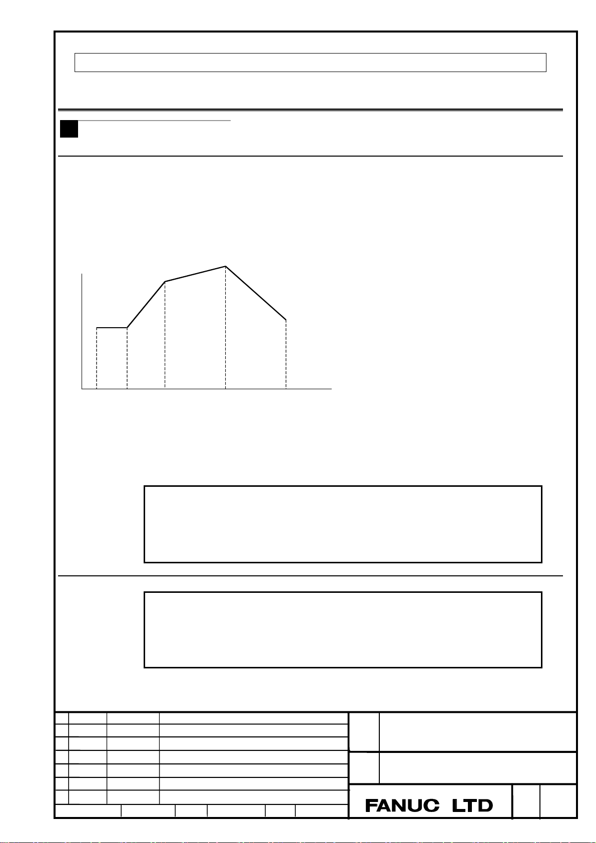
Specify the rate feed mode with G93.2, and directly specify a tool end feedrate as a numeric value after F. By using the value of F in
the previous block as the initial value, a machine is accelerated or decelerated linearly. The unit of the value of F is mm/min or
inch/min. G93.2 is modal. G93.2, once specified, remains to be valid until G93 (inverse time feed) or G94 (feed per minute) or G95
(feed per revolution) is specified.
F
f0
x0
f1
x1 x2 x3
N10 G01 Xx0 Ff0 ;
N20 G93.2 Xx1 Ff1 ;
N30 Xx2 Ff2 ;
N40 Xx3 Ff3 ;
f2
f3
t
Note
1. When axes are accelerated, a feedrate is limited by the parameter No. 1430 (FEDMX) used
to specify an ordinary upper feedrate limit.
2. When the interpolation except the linear interpolation or circular interpolation is specified, an
alarm PS0522 is generated.
Format
G93.2 IP_F_; Rate feed command
IP_:
F_ :Speed in the end point
Ed. Date Design Description
Date Design. Apprv.
For an absolute programming, the coordinates of an end point, and for an
incremental programming, the distance of the tool move
.
Title
Draw
No.
FANUC Series 30i/31i/32i-A, 31i-A5
Rate Feed function
B-63944EN/03-05
page
2/7
Page 4
Explanation
About the initial speed
The initial speed of the rate feed of each block is decided depending on the speed of the previous block, and the initial speed becomes
0 if the feed type of the previous block is specified excluding a cutting feed (feed per minute) or the rate feed.
About the movement during the rate feed
During the rate feed, when each signal such as single block or override is operated, the feed rate is changed as (1) to (3).
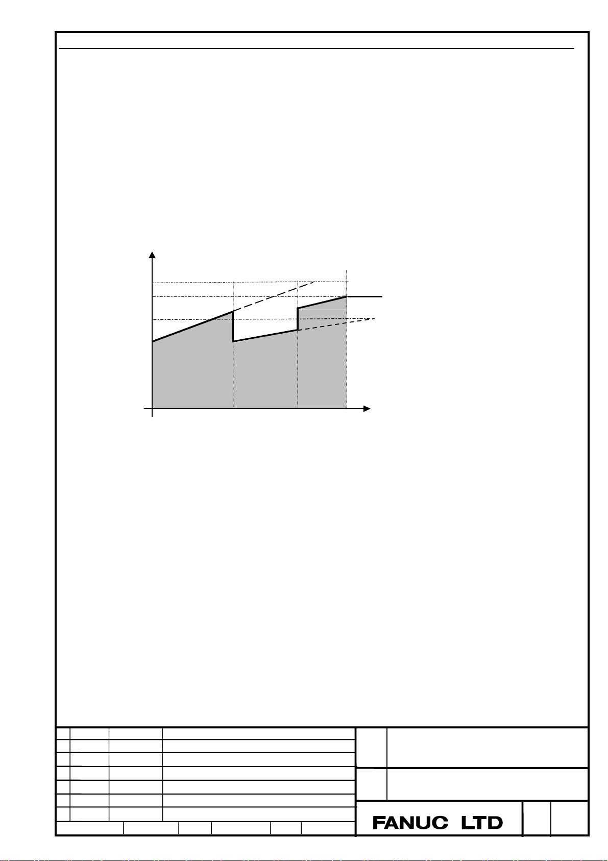
(1) When the feedrate override is change during the rate feed.
(the feedrate override, the second feedrate override, override cancel signal etc.)
When the speed is changed by the feedrate override, acceleration/deceleration is changed according to it, because present speed and
speed at the end point are changed. Speed in the end point becomes a speed after the override is multiplied.
(Example) When the feedrate override is changed from 100% to 70% and to 90%.
(Feedrate) F
Speed in the
end point
100%
90%
70%
100%→70%
Change of the feed override
*Note The feedrate in the figure shows the command feedrate exclusive of acceleration/deceleration after interpolation.
70%→90%
Next
block
(Time) t
FANUC Series 30i/31i/32i-A, 31i-A5
Ed. Date Design Description
Date Design. Apprv.
Title
Draw
No.
Rate Feed function
B-63944EN/03-05
page
3/7
Page 5

(2) When the speed is changed during the rate feed (Dry run signal, External deceleration signal)
A machine is accelerated or decelerated from present speed to the dry run speed when the dry run speed is selected. A machine is
accelerated or decelerated to the former end speed when the dry run speed is released.
(Example) When the dry run speed is selected and released.
F
Speed in the
end point
Dry run
speed
Changing to the
dry run speed
Releasing of the
dry run speed
Next
block
t
(3) When the operation is stopping and restarting during the rate feed. (By feed hold, Interlock signal, Single block operation)
When the feed hold operation is executed during automatic operation and the operation is restarted, the speed at the interrupted point
is applied as restarting feedrate.
(Example) When the feed hold stop is operated and restarted during automatic operation
F
Speed in the
end point
Speed when
interrupted
Operation
stop
Operation
restart
Ed. Date Design Description
Date Design. Apprv.
Next
block
t
FANUC Series 30i/31i/32i-A, 31i-A5
Title
Draw
Rate Feed function
B-63944EN/03-05
No.
page
4/7
Page 6
Y
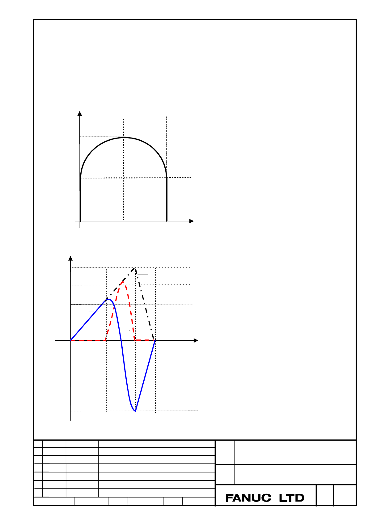
(4) When the axes more than two are interpolated(linear interpolation, circular interpolation)
Tangential speed becomes a speed of the rate feed at the start point and the end point
between blocks, in which linear interpolation was commanded with multi axes.
In case that the movement direction is changed between blocks, the speed of each axis at the end point of previous block does not
correspond with the speed of each axis at the start point of current block.
(Example1) When the continuous blocks of linear interpolation and circular interpolation are commanded with two axes X and Y
N0001 G93.2 G91 G01 Y30. F100;
N0002 G02 X60. R30. F200;
N0003 G01 Y-30. F0;
60.000
30.000
(2)
F
200
100
0
0
Y axis
Tool path of X and Y axis
Tang e n t i a l S p e e d
X axis
60.000 30.000
X
t
-200
Speed change of X and Y axis
FANUC Series 30i/31i/32i-A, 31i-A5
Title
Ed. Date Design Description
Date Design. Apprv.
Draw
No.
Rate Feed function
B-63944EN/03-05
page
5/7
Page 7

Y
X
(Example2) When the continuous blocks of linear interpolation are commanded with two axes X and Y
N0001 G93.2 G91 G01 X30. Y20. F100;
N0002 X10. Y30. F200;
50.000
20.000
0
X axis speed
at the end
point of N1
block
Y axis speed
at the end
point of N1
block
Tool path of X and Y axis
F
0
30.000
Y axis
40.000
X axis
X
Tangential
speed
Y axis
X axis
Y axis speed
at the start
point of N2
block
axis speed
at the start
point of N2
block
t
Title
Ed. Date Design Description
Date Design. Apprv.
Draw
No.
Rate Feed function
B-63944EN/03-05
page
6/7
FANUC Series 30i/31i/32i-A, 31i-A5
Page 8

(5) When the interpolations except G01 liner interpolation, G02/G03 circular interpolation are specified
(Helical interpolation, Hypothetical axis interpolation, Exponential interpolation, Involute interpolation, Spiral interpolation, and
Conical interpolation, Cylindrical interpolation etc.)
An alarm (PS0522) will be issued.
(6) When AI contour control is executed.
An alarm (PS0522) will be issued.
(7) When retrace is executed
The rate feed cannot be retraced. When the rate feed is commanded during reverse, retrace is finished then and displayed ‘RVED’.
(8) Other functions
- 3D interference check with Open CNC cannot be used.
- Do not specify Coordinate system rotation, Three-dimensional coordinate system conversion or Tilted working plane command
during the rate feed mode.
Alarm
Number Message Description
PS0522 ILLEGAL CMD. IN RATE
FEED(G93.2)
During AI contour control mode or the
interpolation except linear interpolation, circular
interpolation is commanded in the rate feed.
FANUC Series 30i/31i/32i-A, 31i-A5
Ed. Date Design Description
Date Design. Apprv.
Title
Draw
No.
Rate Feed function
B-63944EN/03-05
page
7/7
Page 9

FANUC Series 30i /31i-A, 31i-A5
Rigid Tapping By Manual Handle
1. Type of applied technical documents
Name
FANUC Series 30i –MODEL A
FANUC Series 31i –MODEL A
FANUC Series 32i –MODEL A
Common to Lathe System / Machining Center System
OPERATOR’S MANUAL
Spec.No./Version
2. Summary of change
Group Name / Outline New,
Basic
Function
Optional
Function
Unit
Maintenance
parts
The description about Rigid Tapping By Manual Handle is added. Add
B-63944EN/04
Applicable
Add,
Correct,
Delete
Date
Immediately
ED
Date
Notice
Correction
Another
Date
Design
FANUC Series 30i/31i -A, 31i -A5
Rigid Tapping By Manual Handle
B-63944EN/04-02
1/2
2010.06.07
Design
Title
Draw
No.
Description Page
Approve
Page 10

Add the following description in Limitation of Ⅲ.OPERATION 3.7 “RIGID TAPPING BY MANUAL
HANDLE”.
- Feed forward
In rigid tapping by manual handle, feed forward is disabled even if bit 2 (RFF) of parameter No. 5203 is set to 1
(Feed forward is enabled in rigid tapping).
ED
Date
Date
Design
2010.06.07
Design
Title
Draw
No.
Description Page
Approve
FANUC Series 30i/31i -A, 31i -A5
Rigid Tapping By Manual Handle
B-63944EN/04-02
2/2
Page 11

FANUC Series 30i-MODEL A
FANUC Series 31i-MODEL A
FANUC Series 32i-MODEL A
Correction of Common to Lathe System/Machining Center System OPERATOR'S
1. Type of applied technical documents
FANUC Series 30i-MODEL A
FANUC Series 31i-MODEL A
Name
FANUC Series 32i-MODEL A
Common to Lathe System/Machining Center System
OPERATOR'S MANUAL
Spec.No./Version
B-63944EN/04
2. Summary of change
Group Name / Outline
Basic Function
Optional Function
The description of “II.4.12 Smooth
Interpolation” was corrected.
Unit
Maintenance
parts
Notice
Correction
Another
MANUAL
New, Add,
Correct,
Delete
Correct
Applicable
Date
Immediately
Ed. Date Design Description
Date 14.Jun.2010 Design. Apprv.
FANUC Series 30i-MODEL A
FANUC Series 31i-MODEL A
FANUC Series 32i-MODEL A
Title
Correction of Common to Lathe System/Machining Center System OPERATOR'S MANUAL
Draw
No.
B-63944EN/04-03
page
1/2
Page 12

p
Please replace the content of "II.4.12 Smooth Interpolation" from the term of "Automatically
turning on and off AI contour control with smooth interpolation" to the term of "Checking the
smooth inter
olation mode" (p.90-p.91)with the following content.
- Automatically turning on and off AI contour control with smooth interpolation
Specifying G5.1 Q2 also enables smooth interpolation and AI contour control to be turned on at the same time.
The automatic velocity control by AI contour control reduces impacts on the mechanical system. Specifying
G5.1 Q0 cancels the smooth interpolation mode and the AI contour control mode at the same time.
- Conditions for enabling smooth interpolation
Smooth interpolation is performed when all the following conditions are satisfied. If any of the following
conditions is not satisfied for a block, that block is executed without smooth interpolation then the conditions
are checked for the next block.
(1) The travel distance of a block is shorter than the length specified with parameter No. 8486.
(2) The travel distance is other than 0.
(3) The modes are:
G01 : Linear interpolation
G13.1 : Polar coordinate interpolation cancel
G15 : Polar coordinate command cancel
G40 : Tool radius/tool nose radius compensation cancel (except for 3-dimensional cutter compensation)
G64 : Cutting mode
G80 : Canned cycle cancel
G94 : Feed per minute
(4) The move command is specified only along the axes specified with G05.1Q2.
(5) Neithor auxiliary and second auxiary functions, subprogram call (M98, M99), nor calling sobprogram in
external memory (M198) are specified.
(6) The block is judged to be suitable for smooth interpolation, as performed with the internal algorithm of the
CNC.
- Commands which cause alarm in smooth interpolation mode
When the following commands are specified in smooth interpolation mode, alarm PS5110 (IMPROPER
G-CODE(AICC MODE)) is issued.
(1) G27 : Reference position return check
(2) G28 : Automatic return to reference position
(3) G29 : Movement from reference position
(4) G30 : 2nd, 3rd, and 4th reference position return
(5) G30.1 : Floating reference position return
When the following commands are specified in smooth interpolation mode, alarm PS5421 (ILLEGAL
COMMAND IN G43.4/G43.5) is issued.
(1) G43.4, G43.5 : Tool center point control
(2) G43.4, G43.5 : Tool posture control
(3) G43.8, G43.9 : Cutting point commands
- Checking the smooth interpolation mode
Diagnostic data (No. 5000#0) indicates whether the smooth interpolation mode is enabled in the current block.
If the smooth interpolation mode is enabled, "smooth interpolation on" bit is set to 1.
Ed. Date Design Description
Date 14.Jun.2010 Design. Apprv.
FANUC Series 30i-MODEL A
FANUC Series 31i-MODEL A
FANUC Series 32i-MODEL A
Title
Correction of Common to Lathe System/Machining
Center System OPERATOR'S MANUAL
Draw
No.
B-63944EN/04-03
page
2/2
 Loading...