

Page 1

FANUC Robot ARC Mate 100i MODEL B
FANUC Robot M-6i MODEL B
MAINTENANCE MANUAL
B--81545EN/01
Page 2

B--81545EN/01
A
ARCMate100i
M
MODEL
B
PREFACE
PREFACE
This manual explains the maintenance and connection procedures for the
mechanical units (R--J3i controller) of the following robots. Before
replacing the purts, determine thespecification number ofthe mechanical
unit.:
Model name Abbreviation
FANUC Robot ARC Mate 100i
MODEL B
(WithJ2 and J3--axis brake)
FANUC Robot ARC Mate 100i
MODEL B
(Withall axes brake)
FANUC Robot M--6i MODEL B
(WithJ2 and J3--axis brake)
FANUC Robot M--6i MODEL B
(Withall axes brake)
RC Mate 100i
MODEL B
--6i
Mechanical unit
specification No.
A05B--1215--B201
A05B--1215--B601
A05B--1215--B202
A05B--1215--B602
Page 3
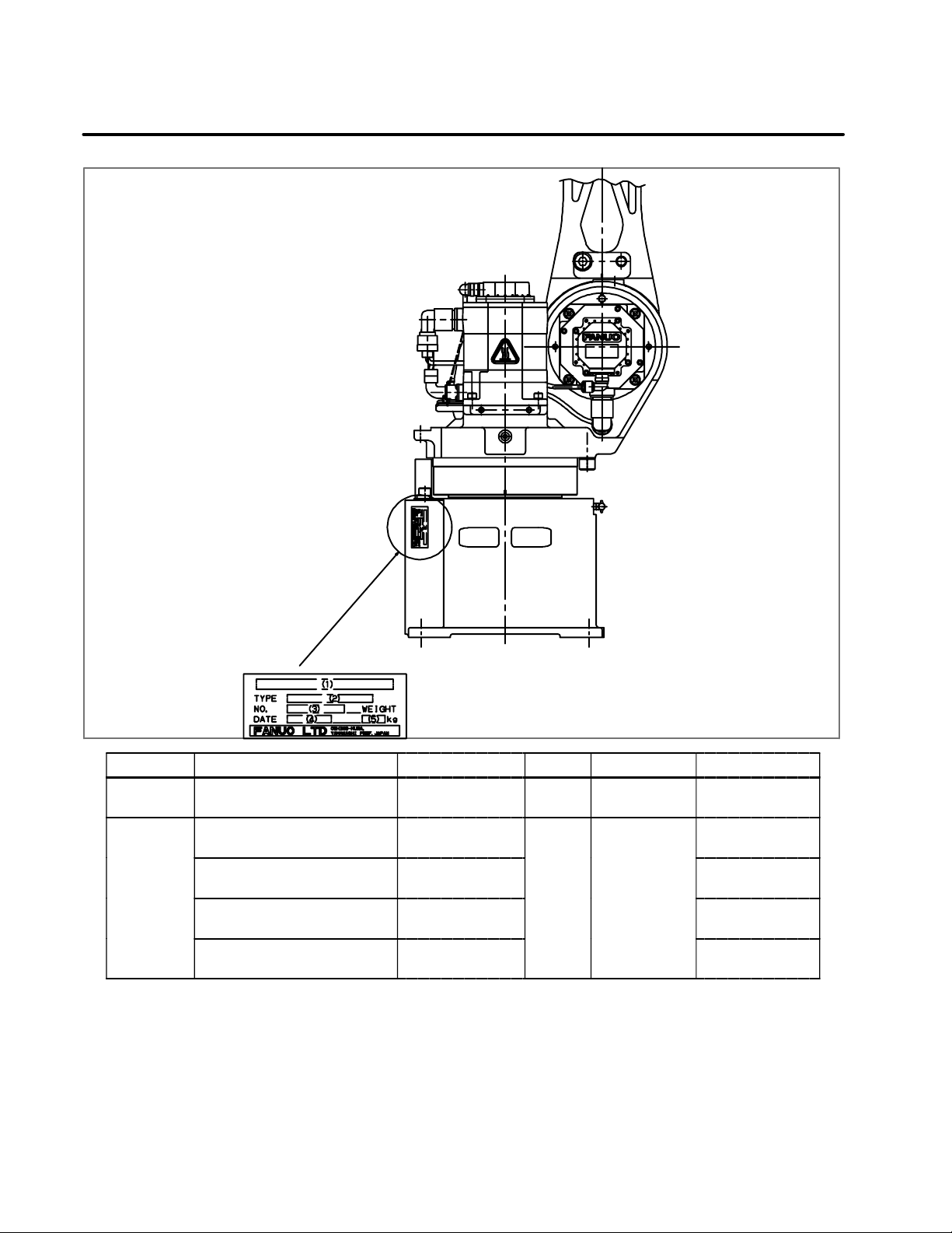
PREFACE
LETTERS
SERIA
L
PRODUCTIO
N
B--81545EN/01
No. (1) (2) (3) (4) (5)
CONTENTS MODEL TYPE No. DATE
FANUC Robot ARC Mate 100i
MODEL B (2-- axis brake)
FANUC Robot ARC Mate 100i
MODEL B (6-- axis brake)
FANUC Robot M--6i MODEL B
(2--axis brake)
FANUC Robot M--6i MODEL B
(6--axis brake)
A05B--1215--B201 184 kg
A05B--1215--B601
A05B--1215--B201
PRINT
NO.
PRINT
PRODUCTION
YEAR AND
MONTH
A05B--1215--B601 138 kg
WEIGHT
(Withoutcontroller)
138 kg
184 kg
Page 4
B--81545EN/01
g
p
PREFACE
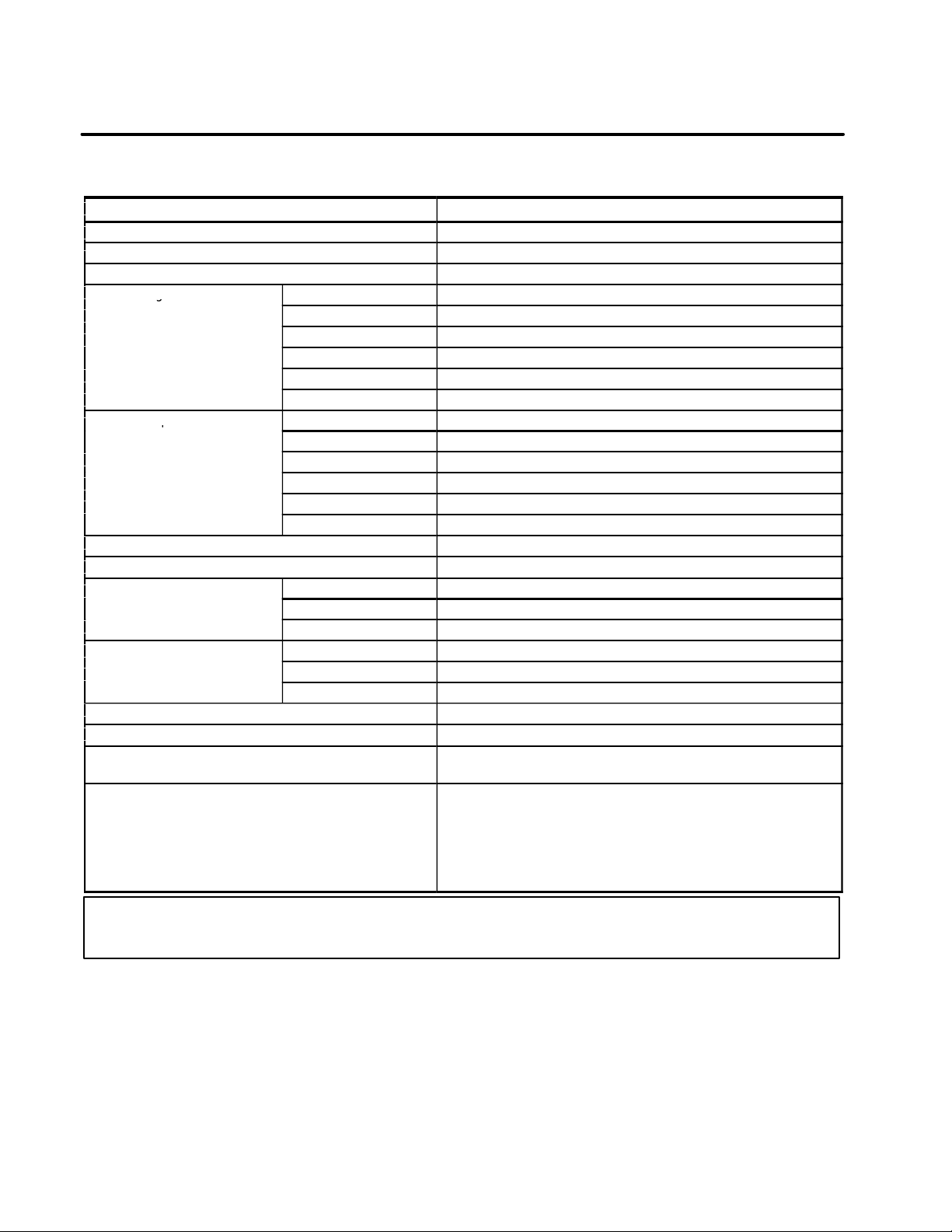
Specification
Item R--2000i/165F
Type Articulated type
Controlledaxes 6 axes (J1, J2, J3, J4, J5, J6)
Installation Floor, Upside--dowm (Wall& Angle mount) (Note 1)
Motion range
(Maximumspeed)
Maximum speed
Max. load capacity at wrist 6kg
Max. load capacity on J3 catting 12kg
Allowableloadmomentatwrist
Allowable load inertiaat wrist
Drive method Electricservo driveby AC servo motor
Repeatability 0.06mm
Weightof mechanicalunit 134kg (2--axis brake type)
Installation environment Ambient temperature : 0 -- 45°C
J1 axis rotation 340° (5.93rad)
J2 axis rotation 250° (4.36rad)
J3 axis rotation 315° (5.60rad)
J4 axis wrist rotation 380° (6.63rad)
J5 axis wrist swing 280° (4.89rad)
J6 axis wrist rotation 720° (12.57rad)
J1 axis 150°/s (2.62rad/s)
J2 axis 160°/s (2.79rad/s)
J3 axis 170°/s (2.97rad/s)
J4 axis 400°/s (6.98rad/s)
J5 axis 400°/s (6.98rad/s)
J6 axis 500°/s (8.73rad/s)
J4 axis 15.7N·m (1.8kgf·m)
J5 axis 9.8N·m (1.0kgf·m)
J6 axis 5.9N·m (0.5kgf·m)
J4 axis 0.63kg·m2(6.4kgf·cm·s2)
J5 axis 0.22kg·m2(2.2kgf·cm·s2)
J6 axis 0.061kg·m2(0.62kgf·cm·s2)
138kg (6--axis brake type)
Ambient humidity : Normally :75%RH or less
: Short time 95%RH or less
(within 1 month)
(No dew or frostallowed)
Vibration : 0.5G (4.9m/s
2
)orless
NOTE
1 Under the installation condition within ( ), the J1 and J2 axis motion range will be limited.
Page 5

PREFACE
B--81545EN/01
Dust--proof/waterproof performance of M--6i B
Normal specification
Wrist+J3 arm IP67
Other part IP54
NOTE
Definition of IP code
Definition of IP 67
6=Dust--tight
7=Protection from water immersion
Definition of IP 54
5=Dust--protected
4=Protection from splashing water
Performance of resistant chemicals and resistant solvents
(1)(1)The robot (including severe dust/liquid protection model) cannot
be used with the following liquids because there is feat that rubber
parts (packing, oil seal, O ring etc.) will corrode.
(a) Organic solvcnts
(b) Coolant including chlorine / gasoline
(c) Acid, alkali and liquid causing rust
(d) Other liquids or solutions, that will harm NBR
(2) When the robots work in the environment, using water or liquid,
complete draining of J1 base must be done. Incomplete draining of
J1 base will make the robot break down.
Page 6

B--81545EN/01
PREFACE
RELATED MANUALS
Safety handbook B--80687EN
All persons who use the FANUC Robot and system de-
signer must read and understand thoroughly this handbook
R--J3i MODEL B controller Setup and Operations
manual
SPOT TOOL
B--81464EN--1
HANDLING TOOL
B--81464EN--2
ARC TOOL
B--81464EN--3
SEALING TOOL
B--81464EN--4
Maintenance manual
B--81465EN
B--81465EN--1
(European
specification)
Mechanical unit Maintenance manual
FANUC Robot ARC Mate
100i B
M--6i B
B--81545EN
For the FANUC Robot series, the following manuals are available:
Intended readers :
All persons who use FANUC Robot, systemdesigner
Topics :
Safety items for robot system design, operation, maintenance
Intended readers :
Operator, programmer, maintenance person, system designer
Topics :
Robot functions, operations, programming, setup, interfaces, alarms
Use :
Robot operation, teaching, system design
Intended readers :
Maintenance person, systemdesigner
Topics :
Installation, connection to peripheral equipment, maintenance
Use :
Installation, start--up, connection, maintenance
Intended readers :
Maintenance person, systemdesigner
Topics :
Installation, connection to the controller, maintenance
Use :
installation, start--up, connection, maintenance
Page 7

B--81545EN/01
Table of Contents
I. MAINTENANCE
1. CONFIGURATION 3............................................................
1.1 J1--AXIS DRIVE MECHANISM 4......................................................
1.2 J2--AXIS DRIVE MECHANISM 5......................................................
1.3 J3--AXIS DRIVE MECHANISM 6......................................................
1.4 J4--AXIS DRIVE MECHANISM 7......................................................
1.5 J5-- AND J6--AXIS DRIVE MECHANISMS 8............................................
1.6 SPECIFICA TIONS OF THE MAJOR MECHANICAL UNIT COMPONENTS 9.................
2. PREVENTIVE MAINTENANCE 11................................................
2.1 DAILY INSPECTION 12.............................................................
2.2 QUARTERLY INSPECTION 14.......................................................
2.3 YEARLY INSPECTION 15...........................................................
2.4 ONE-- AND HALF--YEAR PERIODIC INSPECTION 16...................................
2.5 THREE--YEAR PERIODIC INSPECTION 17............................................
2.6 MAINTENANCE TOOLS 18..........................................................
3. PERIODIC MAINTENANCE 19..................................................
3.1 GREASING 20.....................................................................
3.2 GREASE REPLACEMENT 22........................................................
3.3 BATTERY REPLACEMENT 25.......................................................
4. TROUBLESHOOTING 26......................................................
4.1 OVERVIEW 27.....................................................................
4.2 TROUBLES AND CAUSES 28........................................................
4.3 COMPONENT REPLACEMENT AND ADJUSTMENT ITEMS 31...........................
5. ADJUSTMENTS 32............................................................
5.1 REFERENCE POSITION AND MOVING RANGE 33.....................................
5.2 SIMPLIFIED MASTERING 37........................................................
5.3 MASTERING BY ZERO POSITION MARK ALIGNMENT 39..............................
5.4 JIG--BASED MASTERING 41.........................................................
5.5 CONFIRMING MASTERING 47.......................................................
5.6 J5--AXIS GEAR BACKLASH ADJUSTMENTS 48........................................
5.7 BRAKE RELEASE 50...............................................................
6. COMPONENT REPLACEMENT AND ADJUSTMENTS 52..........................
6.1 REPLACING THE J1--AXIS MOTOR
6.2 REPLACING THE J1--AXIS REDUCER 55..............................................
6.3 REPLACING THE J2--AXIS MOTOR
6.4 REPLACING THE J2--AXIS REDUCER 59..............................................
6.5 REPLACING THE J3--AXIS MOTOR
6.6 REPLACING THE J3--AXIS REDUCER 64..............................................
M1
M2
M3
53...........................................
57...........................................
62...........................................
Page 8

TABLE OF CONTENTS
B--81545EN/01
6.7 REPLACING THE J4--AXIS MOTOR
6.8 REPLACING THE J4--AXIS GEARBOX 67..............................................
6.9 REPLACING THE J5--AXIS MOTOR
6.10 REPLACING THE J5--AXIS GEAR 71..................................................
6.11 REPLACING THE J6--AXIS MOTOR
M4
M5
M6
AND REDUCER 73............................
7. PIPING AND WIRING 77.......................................................
7.1 PIPING DRAWING 78...............................................................
7.2 WIRING DIAGRAMS 79.............................................................
7.3 CABLE MOUNTING DIAGRAM 81...................................................
8. CABLE REPLACEMENT 82....................................................
8.1 CABLE DRESSING 83..............................................................
8.2 REPLACING CABLES 85............................................................
9. COVER OPTION REPLACEMENT 90............................................
9.1 REPLACING THE J2 COVER OPTION (A05B--1210--J401) 91..............................
9.2 REPLACING THE J4 COVER OPTION (A05B--1210--J402) 92..............................
66...........................................
69...........................................
10. M--6i PACKAGES WITH REINFORCED DUST--PROOF AND
DRIP--PROOF CHARACTERISTICS 93.........................................
10.1 DUST--PROOF AND DRIP--PROOF PERFORMANCE OF THE PACKAGES WITH
REINFORCED DUST--PROOF AND DRIP--PROOF CHARACTERISTICS 94..................
10.2 CONFIGURATION OF THE PACKAGES WITH REINFORCED DUST--PROOF AND
DRIP--PROOF CHARACTERISTICS 95.................................................
10.3 CAUTIONS IN SELECTING THE PACKAGES WITH REINFORCED DUST--PROOF
AND DRIP--PROOF CHARACTERISTICS 97............................................
10.4 REPLACING THE COMPONENTS OF THE PACKAGES WITH REINFORCED DUST--PROOF
AND DRIP--PROOF CHARACTERISTICS 98............................................
II. CONNECTION
1. ROBOT OUTLINE DRAWING AND OPERATION AREA DIAGRAM 103.............
1.1 OUTLINE DRAWING AND OPERATION AREA DIAGRAM 104...........................
2. MOUNTING DEVICES ON THE ROBOT 107......................................
2.1 WRIST SECTION END EFFECTOR MOUNTING SURFACE 108...........................
2.2 DEVICE MOUNTING SURFACES 109.................................................
2.3 SETTING THE SYSTEMVARIABLES FOR SHORTEST--TIME CONTROL 111...............
2.4 WRIST LOAD CONDITIONS 114.....................................................
2.5 END EFFECTOR AIR PIPING 115.....................................................
2.6 END EFFECTOR INPUT SIGNALS (RDI/RDO) 116......................................
2.7 CONNECTOR SPECIFICATIONS 117..................................................
Page 9

B--81545EN/01
TABLE OF CONTENTS
3. TRANSPORTATION AND INSTALLATION 118....................................
3.1 TRANSPORTATION 119.............................................................
3.2 STORING THE ROBOT 121..........................................................
3.3 INSTALLATION 122................................................................
3.4 MAINTENANCE CLEARANCE 125...................................................
3.5 ASSEMBLING THE ROBOT FOR INSTALLATION 127...................................
3.6 AIR PIPING 128....................................................................
3.7 INSTALLATION CONDITIONS 130...................................................
APPENDIX
A. SPARE PARTS LISTS 133.....................................................
B. INTRA--MECHANICAL UNIT CONNECTION DIAGRAMS 139......................
C. PERIODIC INSPECTION TABLE 144............................................
D. BOLT MOUNTING TORQUE LIST 145...........................................
Page 10

I. MAINTENANCE
Page 11
B--81545EN/01
1
1. CONFIGURATIONMAINTENANCE
CONFIGURATION
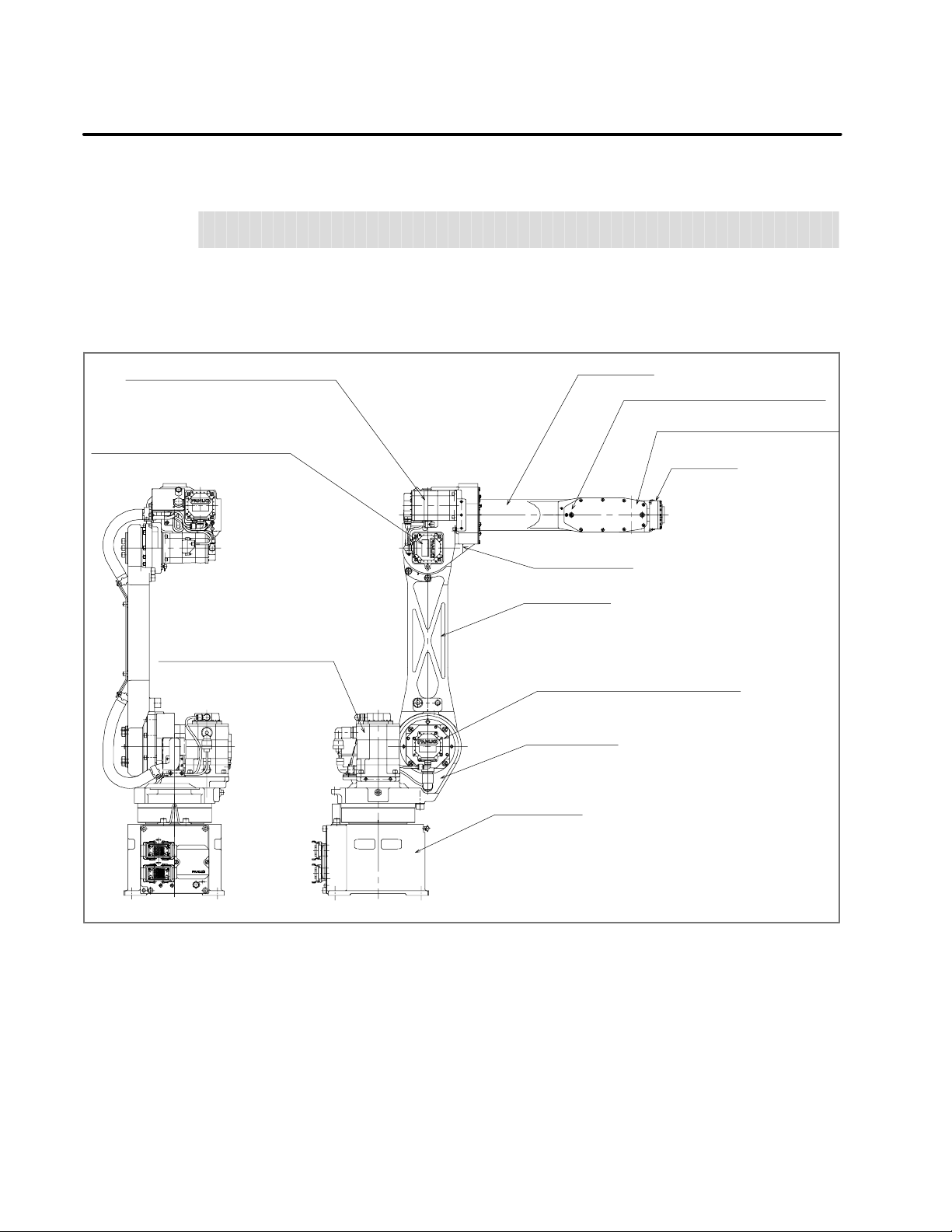
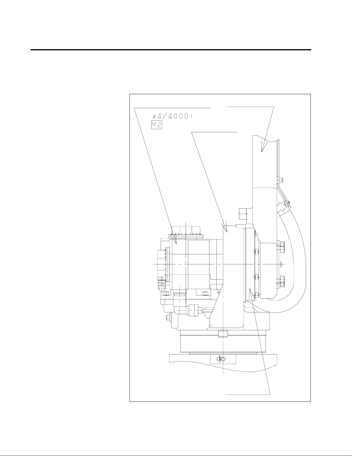
Fig. 1 shows the configuration of the mechanical unit.
AC servo motor forJ4--axis (M4)
AC servo motor forJ3--axis (M3)
AC servo motor forJ1--axis (M1)
J3--axis arm
AC servo motor forJ5--axis (M5)
AC servo motor forJ6--axis (M6)
Wristunit
J3--axis casing
J2--axis arm
AC servo motor forJ2--axis (M2)
J2--axis base
J1--axis base
Fig 1 Mechanical unit configuration
Page 12
1. CONFIGURATION
MAINTENANCE
B--81545EN/01
1.1
J1--AXIS DRIVE
MECHANISM
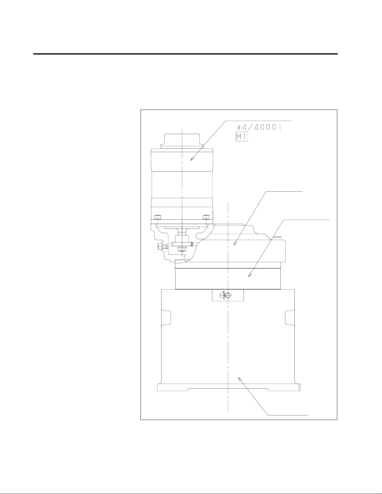
Fig. 1.1 shows the J1--axis drive mechanism.
TheJ1--axis drivemechanismisconfiguredinsuch a waythattheJ2--axis
base is rotated by reducing the rotation speed of an AC servo motor with
a reducer.
The J2--axis base is supported on the J1--axis base through the reducer.
J1--axis AC servo motor
J2--axis base
J1--axis reducer
J1--axis base
Fig 1.1 J1--axis drive mechanism
Page 13
B--81545EN/01
1. CONFIGURATIONMAINTENANCE
1.2
J2--AXIS DRIVE
MECHANISM
Fig. 1.2 shows the J2--axis drive mechanism. The J2--axis drive
mechanismis configuredin such a waythat the J2--axis armis rotatedby
reducing the rotation speed of an AC servo motor with a reducer.
The J2--axis arm is supported on the J2--axis base through the reducer.
J2--axis AC servo motor
J2--axis base
J2--axis arm
J2--axis reducer
Fig 1.2 J2--axis drive mechanism
Page 14
1. CONFIGURATION
MAINTENANCE
B--81545EN/01
1.3
J3--AXIS DRIVE
MECHANISM
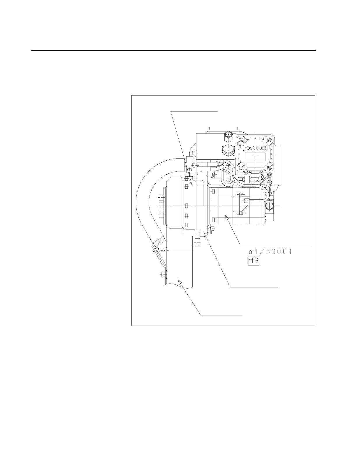
Fig. 1.3 shows the J3--axis drive mechanism. The J3--axis drive
mechanism is configured in such a way that the J3--axis casing is rotated
by reducing the rotation speed of an AC servo motor with a reducer.
The J3--axis casing is supported on the J2--axis arm through the reducer.
J3--axis reducer
J3--axis AC servo motor
J3--axis casing
J2--axis arm
Fig 1.3 J3--axis drive mechanism
Page 15
B--81545EN/01
1. CONFIGURATIONMAINTENANCE
1.4
J4--AXIS DRIVE
MECHANISM
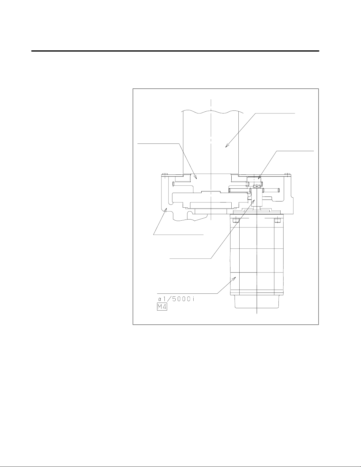
Fig. 1.4 shows the J4--axis drive mechanism. The J4--axis drive
mechanismis configuredin such a waythat the J3--axis armis rotatedby
reducing the rotation speedof an AC servo motor with a two--stage gear.
J3--axis arm
Final gear
Second gear
J3--axis casing
Input gear
J4--axis AC servo motor
Fig 1.4 J4--axis drive mechanism
Page 16
1. CONFIGURATION
MAINTENANCE
B--81545EN/01
1.5
J5-- AND J6--AXIS
DRIVE MECHANISMS
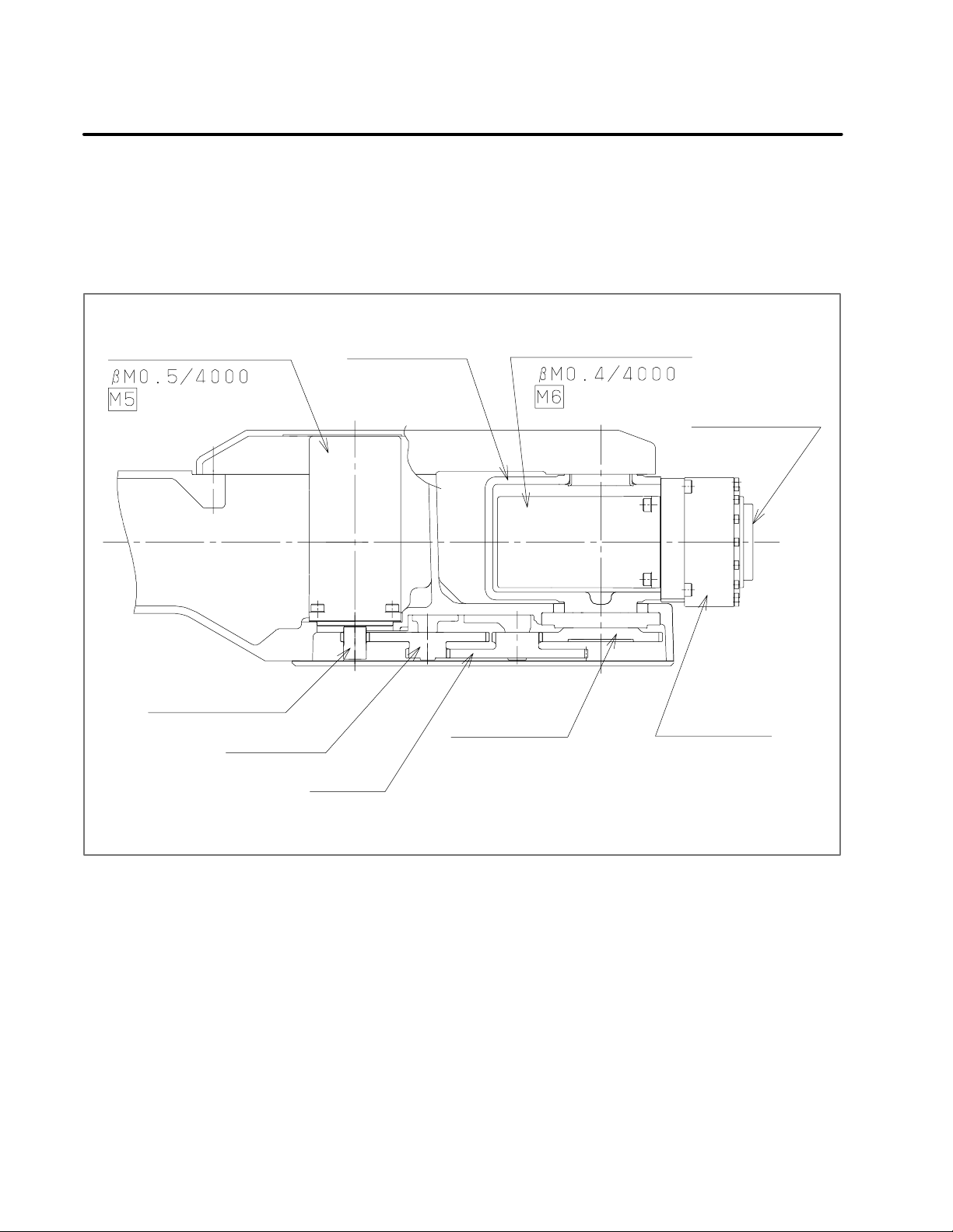
Fig. 1.5 shows the J5-- and J6--axis drivemechanisms. TheJ5--axis drive
mechanism is configured in such a waythat the J6--axis unit is rotated by
reducingthe rotation speedofan AC servomotor witha three--stage gear.
The J6--axis drivemechanism is configured in such a way that theoutput
flangeisrotatedby reducingtherotationspeedofanACservo motorwith
a reducer.
J5--axis AC servo motor J6--axis unit J6--axis AC servo motor
Output flange
Input gear
Second gear
Final gear
Third gear
Fig 1.5 J5-- and J6--axis drive mechanisms
J6--axis reducer
Page 17

B--81545EN/01
1. CONFIGURATIONMAINTENANCE
1.6
SPECIFICATIONS OF
THE MAJOR
MECHANICAL UNIT
COMPONENTS
1) Motors
ARC Mate 100i MODEL B
(two--axis, equipped with a brake): A05B--1215--B201
M--6i MODEL B
(two--axis, equipped with a brake): A05B--1215--B202
Specification Axis Remark
A06B-0223-B005 J1 α 4/4000i
A06B-0223-B605 J2 α 4/4000i Equipped witha brake
A06B-0202-B605 J3 α 1/5000i Equipped witha brake
A06B-0202-B005 J4 α 1/5000i
A06B-0115-B075#0008 J5 β M0.5/4000
A06B-0114-B075#0008 J6 β M0.4/4000
ARC Mate 100i MODEL B
(six--axis, equipped with a brake): A05B--1215--B601
M--6i MODEL B
(six--axis, equipped with a brake): A05B--1215--B602
Specification Axis Remark
A06B-0223-B605 J1 α 4/4000i Equipped witha brake
A06B-0223-B605 J2 α 4/4000i Equipped witha brake
A06B-0202-B605 J3 α 1/5000i Equipped witha brake
A06B-0202-B605 J4 α 1/5000i Equipped witha brake
A06B-0115-B275#0008 J5 β M0.5/4000
Equipped with a brake
A06B-0114-B275#0008 J6 β M0.4/4000
Equipped with a brake
2) Reducers
Specification Axis
A97L-0218-0288#33 J1
A97L-0218-0289#153 J2
A97L-0218-0295#161 J3
A97L-0218-0224 J6
3) J4--axis gearbox
Specification Axis
A05B-1215-K401 J4
Page 18

1. CONFIGURATION
MAINTENANCE
4) Gears
Specification Axis
A290-7215-X511 J5
A290-7215-V501 J5
A290-7215-V502 J5
A290-7215-X514 J5
5) Stoppers
Specification Axis
B--81545EN/01
A290-7215-X241 J1
A290-7215-X323 J2
A290-7215-X324 J3
Note) 330° stopper
Page 19

B--81545EN/01
2
2. PREVENTIVE MAINTENANCEMAINTENANCE
PREVENTIVE MAINTENANCE
Performing daily inspection, periodic inspection, and maintenance can
keep the performance of robots in a stable state for a long period.
Page 20

2. PREVENTIVE MAINTENANCE
MAINTENANCE
B--81545EN/01
2.1
DAILY INSPECTION
Clean and maintain each component of robots during everyday system
operations. At the same time, check the components to see if there is a
crack or break in them. Also check and maintain the following items as
required.
a) Before automatic operation
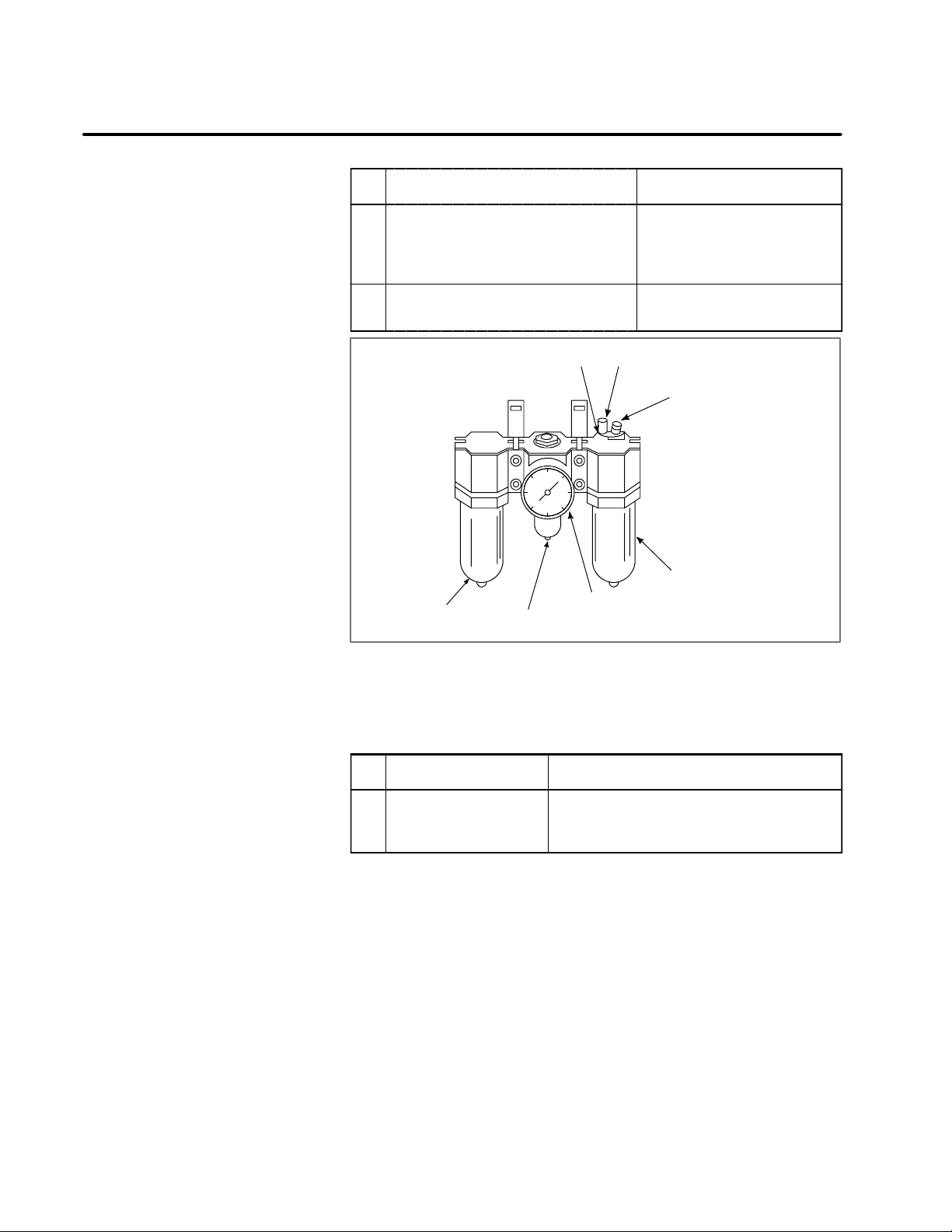
No. Inspection item Inspection procedure
1 Pneumatic pressure
check
2
For
machines
with a
three--piece
pneumatic
option
Check on the amount of
oil mist
Make a pneumatic pressure
check, using the three--piece
pneumatic option shown in Fig.
2.1.
Ifthemeasuredpneumaticpressure does not fall in the range
between0.5and 0.7MPa(5and
7kg/cm
usingtheregulatorpressuresetting handle.
Putthepneumaticpressuresystem in operation and check the
amount of oil dripping. If the
measuredamountof oildripping
does not meet the rating (one
drop/10 to 20 seconds), make
adjustments, using the oil adjustment knob. The oiler becomes empty after10to 20 days
of normal operation.
2
), make adjustments,
3 Check on the amount of
oil
4 Check for leakage from
the piping
5 Whethercables are abnormal
Mechanical unit
6 Battery voltagecheck Make sure that when thepower
7 Whether there is any abnormal vibra-
tion,noise,or heatgenerationin motors
8 Whetherthereisa change topositioning
precision
Check to see iftheamount of oil
inthethree-- piece option is within the rated level shown in Fig.
2.1.
Check to see if a joint or hose
leaks.
Ifyou finda problem, tighten the
joint or replace any defective
component.
See Chapter8.
isturnedon,theBLAL alarmhas
not been raised. If the BLAL
alarm has been raised, replace
the battery as directed in Section 3.3.
Check thateach axis is running
smoothly.
Check to see if thereis any displacement from the previous
positionand there are variations
in the stop position.
Page 21
B--81545EN/01
2. PREVENTIVE MAINTENANCEMAINTENANCE
No. Inspection procedureInspection item
9 Reliable operation of peripheral equip-
ment
10 Check on the operation of the J2-- and
J3--axis brakes.
Oiler’s oil inlet
Filter
Regulator pressure setting handle
Fig 2.1 Three--piece pneumatic option
Pressure gauge
Check to see if the machine operates exactly according to
directionsfromtherobotandperipheralequipment.
See Section4.2.
Oileradjustmentknob
Check oiler’s oil level
Oiler
b) After automatic operation
Once you are finishedwith automatic operation, bring therobot to its
reference position, and turn it off.
No. Inspection item Inspection procedure
1 Componentcleaning
and inspection
Clean and maintain each component. At the
same time, check the components to see if
there is a crack or break in them.
Page 22

2. PREVENTIVE MAINTENANCE
MAINTENANCE
B--81545EN/01
2.2
QUARTERLY
INSPECTION
Inspectthe following items at regularintervalsof threemonths. Increase
the locations and the frequency of i nspection if the conditions under
which the robot is used and the environment in which it runs require so.
No. Inspection item Inspection procedure
1 Loose connector Check that themotor connectors or other con-
nectors are not loose.
2 Loose bolt Check thatthecoverretainingboltsorexternal
bolts are not loose.
3 Debris removal Remove any spatter, debris,anddust from the
mechanical unit.
Page 23

B--81545EN/01
2. PREVENTIVE MAINTENANCEMAINTENANCE
2.3
YEARLY INSPECTION
Inspect the following item at regular intervals of one year.
No. Inspection item Inspection procedure
1 Greasing See Section 3.1.
Page 24

2. PREVENTIVE MAINTENANCE
MAINTENANCE
B--81545EN/01
2.4
ONE-- AND
HALF--YEAR
PERIODIC
INSPECTION
Performthe followinginspection/maintenanceitem at regularintervalsof
one year and half.
No. Inspection item Inspection procedure
1 Battery replacement Replace the battery in the mechanical unit.
(See Section 3.3.)
Page 25

B--81545EN/01
2.5
2. PREVENTIVE MAINTENANCEMAINTENANCE
THREE--YEAR
PERIODIC
INSPECTION
No.
1 Greasereplacement See Section3.2.
Inspection item Inspection procedure
Page 26

2. PREVENTIVE MAINTENANCE
MAINTENANCE
B--81545EN/01
2.6
MAINTENANCE
TOOLS
You should have the following instruments and tools ready for
maintenance.
a) Measuring instruments
Instrument Condition Use
Dial gauge 1/100mm Forpositioningprecision and backlash
measurement
Calipers 150mm
b) Tools
Phillips screwdrivers (large, medium, and small sizes)
Flat--blade screwdrivers (large, medium, and small sizes)
Box wrenches (M3 to M6)
Allen wrenches (M3 to M16)
Torque wrench
Long T wrenches (M5 and M6)
Adjustable wrenches (medium and small sizes)
Pliers
Long--nose pliers
Cutting pliers
Both--ended wrench
Grease gun
C--ring pliers
Flashlight
Page 27

B--81545EN/01
3
3. PERIODIC MAINTENANCEMAINTENANCE
PERIODIC MAINTENANCE
Page 28
3. PERIODIC MAINTENANCE
MAINTENANCE
B--81545EN/01
3.1
GREASING
When greasing the robot, keep its power turned off.
i) Roughly speaking, replenish the robot with grease once a year.
ii) See Fig. 3.1 and Table 3.1 for greasing points and the method.
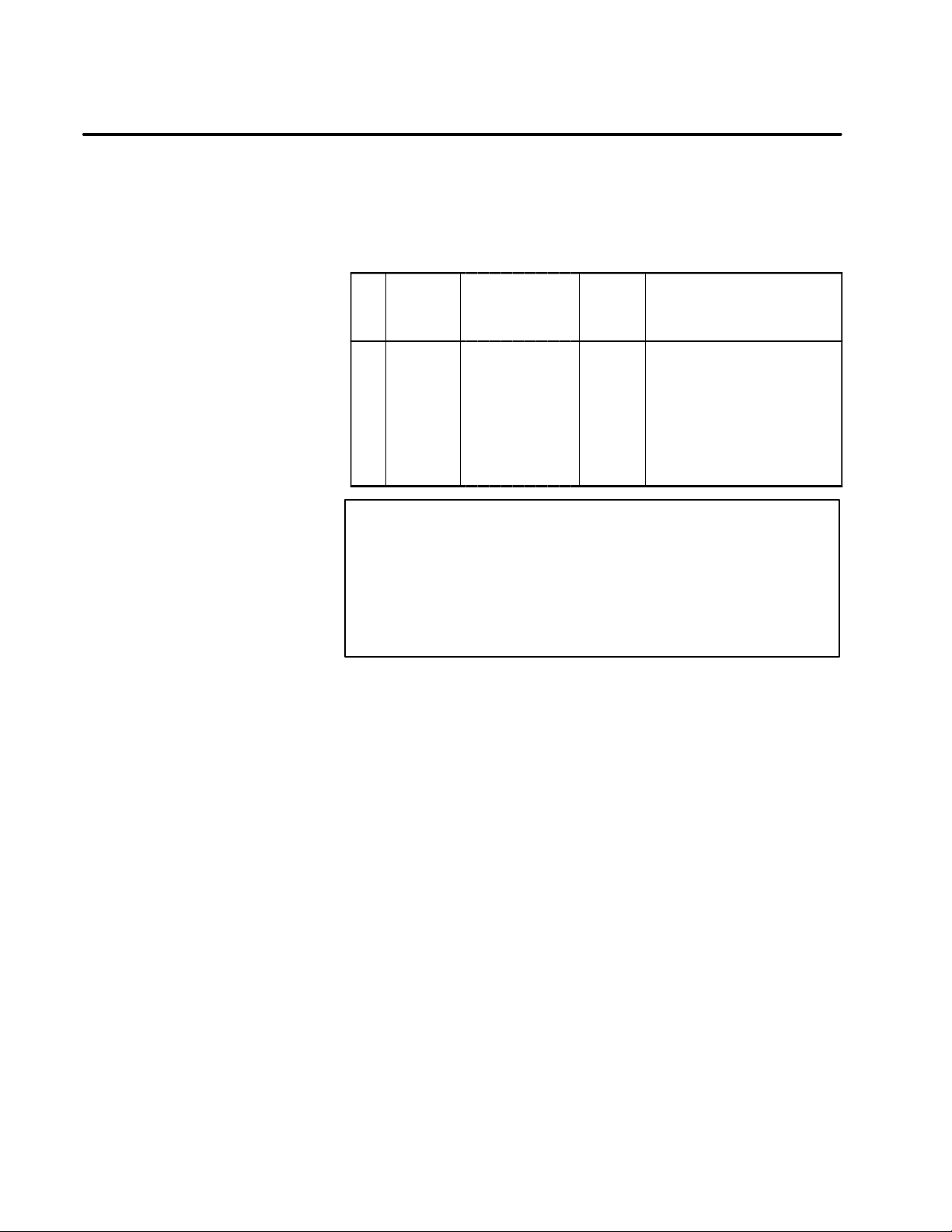
Table. 3.1 Greasing points
Greasing
No.
1 J6--axis
point
reducer
Specified
grease
Mori White
RE No.00
(Specification:
A97L-0040-0119)
Amount
of
grease
40cc J6--axis grease inlet and out-
Greasing method
let, and attach the supplied
greasenipple to the greaseinlet. Aftergreasing, remove the
grease nipple, and attach the
flat--head bolts and sealing
washers to the grease inlet
and outlet.
CAUTION
If you grease incorrectly, the pressure in the grease bath
may increase steeply, leading to a broken seal, which will
eventually cause grease leakage or malfunction.
When greasing, be sure to follow the cautions stated in
Section 3.2.
Page 29
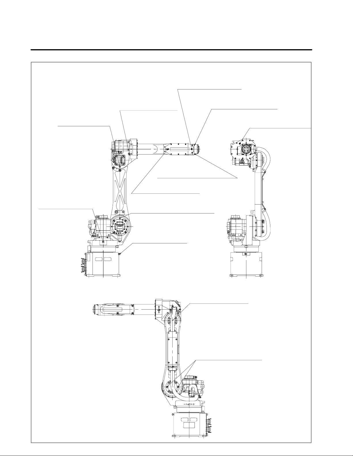
B--81545EN/01
Grease nipple at the
grease inlet for the
J3-axis reducer
Seal bolt at the
grease outlet for the
J1-axis reducer
Low head bolt and seal
washer at the grease outlet
for the J5-axis reducer
Grease nipple at the
grease inlet for the
J4-axis reducer
Low head bolt and
seal washer at the grease
outlet for the J6-axis reducer
Low head bolt and seal washer at the
grease inlet for the J5-axis reducer
Grease nipple at the grease inlet
for the J2-axis reducer
3. PERIODIC MAINTENANCEMAINTENANCE
Low head bolt and seal
washer at the grease outlet
for the J6-axis reducer
Low head bolt and seal
washer at the grease outlet for the J4-axis reducer
Grease nipple at the
grease outlet for the
J1-axis reducer
Seal bolt at the
grease outlet for the
J3-axis reducer
Seal bolt at the
grease outlet for the
J2-axis reducer (2 locations)
Fig 3.1 Greasing points
Page 30

3. PERIODIC MAINTENANCE
greasetob
e
turewhe
n
(
S
ificat
i
MAINTENANCE
B--81545EN/01
3.2
GREASE
REPLACEMENT
Follow the procedure stated below to replace the grease in the J1--, J2--,
and J 3--axis reducersand theJ4-- and J5--axis gearboxesonce every three
yearsor after11,520hours of operation. See Fig. 3.1for greasingpoints.
1) Remove the seal bolts from the J1--, J2--, and J3--axis grease outlets
shown in Fig. 3.1. Also remove the flat--bolts and sealing washers
from the J4-- and J5--axis grease outlets.
2) Uncap thegreasenipplesat theJ1--, J2--, J3--, andJ4--axis greaseinlets.
Remove the flat--head bolt fromthe J5--axis grease inlet and attach the
supplied grease nipple to the J5--axis grease inlet.
3) Supply the grease specified in Table 3.2 to the J1--, J2--, and J3--axis
reducers, and J4-- and J5--axis gearboxes through their respective
greasenipples. Keepgreasing untilthe newgrease pushesout theold
grease and comes out from each grease outlet. Ensurethat the amount
of the newly supplied grease equals the amount of the drained grease
so that the grease bath will not become full.
4) Wind sealing t ape around the J1--, J2--, and J3--axis seal bolts you
removed, and attach them to the respective grease outlets.
5) Attach the J4-- and J5--axis flat--head bolts and t he J4-- and J5--axis
sealing washers to the respective grease i nlets and outlets.
Table. 3.2 Grease to be replaced at regular intervals of three years
Specified grease Amount of
Robot pos-
Kyodo Yushi
J1--axis reducer
J2--axis reducer
J3--axis reducer About300 -J4--axis gearbox About 700 -J5--axis gearbox About 400 J4=+90°
Mori White RE No.00
pec
A98L-0040-0119#2.4KG)
on:
applied (cc)
About 1100 --
About 570 --
greased
Page 31

B--81545EN/01
3. PERIODIC MAINTENANCEMAINTENANCE
CAUTION
If you grease incorrectly, the pressurein the grease bath may
increasesteeply,leadingtoabrokenseal,whichwilleventually
cause grease leakage or malfunction.
When greasing, be sure to follow the cautions stated below.
1 Before starting greasing, open the grease outlets (remove
bolts and the like from the grease outlets).
2 Using a manual greasing pump, grease gently and slowly.
3 Avoid using a pneumatic pump driven from a factory
pneumatic line as much as possible.
Ifyou cannotavoid usingit, observea greasingspeedof 15
2
cc/s or lower and a pressure of 75 kgf/cm
or lower.
4 Be sureto use thespecifiedgrease. Otherwise,damage to
reducers or a similar abnormality may occur.
5 Beforecapping thegreaseoutlets, makesure thata grease
flow from the grease outlet has stopped (the remaining
pressure has been released).
6 Wipe offany greasefromthe floor androbot completely, so
no one will slip on it.
Page 32

3. PERIODIC MAINTENANCE
MAINTENANCE
B--81545EN/01
Whenreplacing or supplying grease, keepthe robot in the postureshown
in Fig. 3.2.
Fig 3.2 Robot posture forgreasing
Axis Posture
Free
Page 33

B--81545EN/01
3. PERIODIC MAINTENANCEMAINTENANCE
3.3
BA TTER Y
REPLACEMENT
A backup batteryis used to keep thereference--position data for eachaxis
of the robot.
The battery needs to be replaced at regular intervals of one year and half.
Follow this procedure for battery replacement.
1) Keep the power turned on.
Press the EMERGENCY STOP button of the robot to keep it from
moving.
2) Uncap the battery case.
3) Take out the battery from the battery case.
4) Insert a new batteryinto the batterycasewhile payingattention to the
polarity of the battery.
5) Cap the battery case.
Batterycase
Cap
Battery specifications : A98L--0031-- 0005
(1.5V size--D 4pcs)
Fig 3.3 Battery replacement
Page 34

B--81545EN/01
4
4. TROUBLESHOOTINGMAINTENANCE
TROUBLESHOOTING
Page 35

4. TROUBLESHOOTING
MAINTENANCE
B--81545EN/01
4.1
OVERVIEW
A trouble with a mechanical unit may occur due to a combination of
multiple causes. It is difficult to find out the true cause,and an incorrect
measure may make the trouble worse. When troubleshooting, it is
important to get hold of the situation of any error accurately and take a
correct measure.
Page 36

B--81545EN/01
4. TROUBLESHOOTINGMAINTENANCE
4.2
TROUBLES AND
CAUSES
Symptom
BZAL alarmissued
(battery zero)
Incorrectpositioning
Table 4.2 (a) lists the major troubles in the mechanical unit and their
causes. Ifyoucannot find a causeaccuratelyordonotknowwhatmeasure
to take, please contact FANUC.
Note, however, that the backlash and drop levels listed, respectively, in
Table 4.2 (b) and Table 4.2 (c) and lower are not abnormal.
Table 4.2 (a) Major troubles and causes (1/3)
Cause Measure Remark
The voltage of the memory
backup battery has dropped.
Broken pulse coder signal
cable
Something hit the robot. Correctthe taught point.
The robotis not firmly fixed. Fix it. See Section 3.2 of Part II,
Peripheral equipment has
shifted.
Load too heavy Reducethe load.
Replace the battery,and perform simplified mastering.
Replace the cable, and perform simplified mastering.
Fix it.
Limitthe operatingcondition.
See Section3.3.
See Section5.3.
See Section8.2.
See Section5.3.
“Connection”.
Load on the wrist:
Refer to “Descriptions”.
Peripheralequipment:
See Section 2.2of Part II,
“Connection”.
Incorrectparametersetting Correct it. Referto“Operator’sManual”.
Broken cable Replace the cable. See Section8.2.
Pulse c oder error Replace the motor. See Sections6.1 to 6.11.
Backlash in the mechanical
unit ---- see the next section.
Page 37

4. TROUBLESHOOTING
MAINTENANCE
Table 4.2 (a) Major troubles and causes (2/3)
B--81545EN/01
Vibration
Symptom
Cause Measure Remark
The robotis not firmly fixed. Fix it. See Section 3.2 of Part II,
“Connection”.
The floor is vibrating (especially when the robot is
installed on the second floor
or above).
Load too heavy Reducethe load.
Servo maladjustment Adjust the servo section. Contact FANUC.
Broken cable Replace the cable. See Section8.2.
Robot not grounded Ground the robot. Referto“MaintenanceManu-
Defective motor Replace the motor. See Sections 6.1 to 6.11.
Defective axis printed--circuit
board
Defective reducer Replacethe reducer. See Sections6.2 to 6.11.
Re--examine the location of
installation.
Limitthe operatingcondition
Replace the axis printed--circuit board.
Load on the wrist:
Refer to “Descriptions”.
Peripheralequipment:
See Section 2.2of Part II,
“Connection”.
al for the Controller”.
Referto “MaintenanceManual for the Controller”.
Backlash or wobbling
Abnormal sound
Invalid time constant setting Change the time constant. Referto“Operator’sManual”.
Backlash in the mechanical
unit ---- see the next section.
Loose screw or pin Tighten it (and apply Loctite
to it if specified so)
Defective reducer Replacethe reducer. See Sections6.2 to 6.11.
Gear maladjustment Adjustthe gear. See Section5.7.
Worn gear Adjustor replace the gear. Contact FANUC.
Worn bearing Replacethe bearing. Contact FANUC.
Broken casting or otherpart Replace the broken compo-
nent.
Insufficientgreaseforgear or
reducer
Foreign matter in gear or re-
ducer
Gear maladjustment Adjustthe gear. Contact FANUC.
Worn gear Adjustor replace the gear. Contact FANUC.
Apply grease. See Sections3.1 and 3.2.
Washthegearor reducerand
apply grease.
Contact FANUC.
See Sections 6.2 to 6.11,3.1,
and 3.2.
Worn bearing Replacethe bearing. Contact FANUC.
Servosectionmaladjustment Adjust the servo section. Contact FANUC.
Page 38

B--81545EN/01
4. TROUBLESHOOTINGMAINTENANCE
Table 4.2 (a) Major troubles and causes (3/3)
Symptom
Abnormal heat generation
Arm drop at power turn--off
Grease leakage
Cause Measure Remark
Insufficientgreaseforgear or
reducer
Non--specified grease used Replace the grease. See Sections3.1 and 3.2.
Load too heavy Reduce the load.
Gear maladjustment Adjustthe gear. Contact FANUC.
Invalid time constant setting Change the time constant
Too large a brake gap Replace the motor. See Sections 6.1 to 6.11.
Brake drive relay contactde-
position
Deteriorated or broken
O--ring, oil seal, or gasket
Broken casting or otherpart Replace the broken compo-
Apply grease. See Sections3.1 and 3.2.
Load on the wrist:
Limitthe operatingcondition.
setting.
Replace the relay Referto“MaintenanceManu-
Replace the O--ring, oil seal,
or gasket.
nent.
Refer to “Descriptions”.
Peripheralequipment:
See Section 2.2of Part II,
“Connection.”
Referto“Operator’sManual”.
al for the Controller”.
Contact FANUC.
Contact FANUC.
Loose screw Tightenit.
Table 4.2 (b) Allowable backlash level for each axis
J1 J2 J3 J4 J5 J6
Backlashintermof
angle (min)
Backlashintermof
displacement(mm)
2.5 2.5 2.5 3.0 4.5 3.0
0.95
(1300)
NOTE
The backlash in term of displacement (mm) is measured in
the direction of rotation at a distance represented with a
value enclosed in parentheses.
Table 4.2 (C) Allowable arm drop
At power turn--off time
At emergency stop time 5mm
0.44
(600)
5mm
0.44
(600)
0.17
(200)
0.2
(200)
0.17
(200)
Page 39

4. TROUBLESHOOTING
MAINTENANCE
B--81545EN/01
4.3
COMPONENT
REPLACEMENT AND
ADJUSTMENT ITEMS
Adjustments are needed after a component is replaced.
The following table lists componentsand the adjustment items that must
be made after their replacement. After replacing a component, make
necessary adjustments according to this table.
Component replacement or
function change
Cable replacement (a) Cable dressing
(b) Simplified mastering
Change to J1--axis stroke (a) Change to stopper position
(b) Change to parameter
Battery replacement
(The battery should be replaced once
a year.)
Replace the battery with the power
kept on.
No adjustmentis needed.
Adjustment item
Page 40

B--81545EN/01
5
5. ADJUSTMENTSMAINTENANCE
ADJUSTMENTS
Each part of the mechanical units of a robot is set to the best condition
beforethe robot is shipped to the customer. The customerdoes not need
to make adjustments on the robot when it is delivered.
If a mechanical unit of the robot has a large backlash because of a
long--term use or component replacement, make adjustments according
to this section.
Page 41

5. ADJUSTMENTS
MAINTENANCE
B--81545EN/01
5.1
REFERENCE
POSITION AND
MOVING RANGE
1) Reference position and operation limit
Each controlled axis is provided with a reference position and
operation limit.
A state in which a controlled axis has reached its operation limit is
known as overtravel (OT). For each axis, an overtravel condition can
be detected at the both ends of it. As long as the robot does not
encountera servo section error or system errorthat causes a reference
position to be lost, the robot is controlled insuch a way that it will not
go out of its operation area.
Fig. 5.1 (a) to Fig. 5.1 (g) show the reference position and operation
area (stroke) of each axis and their mechanical stopper positions.
Fig. 5.1 (h) shows the operation directions (+/-- directions) of each
axis.
Stroke
Mechanical stopper Mechanical stopper
Fig 5.1 (a) J1--axis swiveling (typically 340°)
Note)Motion limit is restricted by the
position of the J3--axis
Mechanical
stopper
Stroke end
Fig 5.1 (b) J2--axis rotation
Stroke endStroke end
Stroke
Stroke end
Mechanical stopper
Page 42

B--81545EN/01
Note)Motion limit is restricted by the
position of the J2--axis
Stroke end
Mechanical
stopper
Mechanical
stopper
Stroke end
Fig 5.1 (c) J3--axis rotation
5. ADJUSTMENTSMAINTENANCE
Stroke
Stroke endStroke end
Note) The mechanical s topper are not provided forJ4--axis
Fig 5.1 (d) J4--axis rotation
Stroke end
Mechanical stopper
Mechanical stopper
Stroke end
Fig 5.1 (e) J5--axis wrist rotation
Stroke
Page 43

5. ADJUSTMENTS
MAINTENANCE
Fig 5.1 (f) J6--axis wristrotation
B--81545EN/01
Stroke endStroke end
Stroke
Mechanical stopper
Stroke end
J3--axis arm
Interference
angle 170°
J2--axis arm
Fig 5.1 (g) J2/J3 limit interference angle
Interference angle 10°
Stroke end
Mechanical stopper
Page 44

B--81545EN/01
5. ADJUSTMENTSMAINTENANCE
Fig 5.1 (h) Operation directions of each axis
Page 45

5. ADJUSTMENTS
MAINTENANCE
B--81545EN/01
5.2
SIMPLIFIED
MASTERING
The term simplified mastering refers to a procedure for resuming the
previous position completely after a pulse coder battery backup is
disconnected because of cable replacement.
Simplifiedmasteringcannotbe usedifthe pulse coderphasehas changed
mechanically because of a motor or reducer having been replaced. To
calibrate the robot position accurately, perform the jig--based mastering
describedinSection5.4.
1) Procedure
Described below is the simplified mastering to be performed with a
posture of zero degrees for all axes after cable replacement.
1 Before replacing the cable, be sure to take note of the system
variable $DMR_GROUP.$MASTER_COUN[1] to [6] (previous
mastering data).
2 Replace the cable according to the cable replacement procedure
describedinSection8.2.
3 If you want to release brake control, set the system variable
$PARAM_GROUP.$SV_OFF_ENB to FALSE for all axes, turn
off the power, and then perform a cold start.
4 After the power is turned on, the alarm message BZAL alarm is
displayed. Select “TRUE” for the system variable
$MCR.SPC_RESET, turn off the power, and then perform a cold
start.
5 After the power is turned on again, the message Pulse not
established is displayed. Rotate each axis through 20° or so in
either (+ or --) direction, using an individual--axis feed command,
and then press the alarm reset key to reset this message.
6 By performing an individual--axis feed command foreach axis, set
the zero--degree mark within +/--1 mm from the scribed line. (See
Fig. 5.2.) If no reference position has been set up at zero degrees
for all axes, using simplified mastering, go to 7. Otherwise, go to
8.
7 Assign the mastering data in $DMR_GROUP.$MASTER_
COUN[1] to [6] that was taken note of at 1 to the system variable
$DMR_GROUP.$REF_CONUT[1] to [6] (simplified mastering
data). Loadthesystemvariable$DMR_GROUP. $REF_POS[1]to
[6] (simplified mastering reference positions) with “0”. Select
“TRUE” for the $DMR_GROUP.$REF_DONE (simplified
mastering completion flag). Now the simplified mastering
reference position has been set up at zero degrees for all axes.
8 Press the screen selection key to select “0” NEXT, and select
SYSTEM from the menu.
9 Press the F1 key TYPE, select the system variable, and set
$MASTER_ENB value inthelist to1. Press theF1 key TYPEand
select MASTER / CAL.
10 Select The system calibration menu from the system positioning
menu, andpress theFAkey YES to performsimplified mastering.
Now the mastering data obtained from the pulse coder counter
valueisset inthesystem variable$DMR_GRP .MASTER_COUN,
and the system variable $DMR_GRP.MASTER_DONE
(mastering completion flag) is set to “TRUE”.
Page 46

B--81545EN/01
5. ADJUSTMENTSMAINTENANCE
11 Select CALIBRATE from the system positioning menu, and press
the F4 key YES Now positioning is carried out, and teaching and
replaying are enabled.
12 After you are finished with mastering, reset the system variable
$MASTER_ENB to 0.
13 If you released brake control before, re--set the system variable
$P ARAM_GROUP.$SV_OFF_ENB for each axis to the previous
value, turn off the power, and then perform a cold start.
Oncemasteringis completed,updatethedatasheetsupplied togetherwith
the robot with the new mastering data ($DMR_GROUP.$MASTER_
COUN[1] to [6]).
J3--axis
J4--axis
J2--axis
J5--axis
J6--axis
J1--axis
Fig 5.2 Marking of the zero--degree position for each axis
Page 47

5. ADJUSTMENTS
MAINTENANCE
B--81545EN/01
5.3
MASTERING BY
ZERO POSITION
MARK ALIGNMENT
Each robot axis is provided with the scribed lines shown in Fig. 5.2 for
positioning. When these markings are aligned to each other, each axis is
at the zero--degree position. If the markings get misaligned because of
motor or reducer replacement, the following procedure can be used for
rough positional calibration. This is a simplified method. To perform
accurate positional calibration, use the jig--based mastering described in
Section 5.4.
1) Procedure (zero--position mastering)
1 If you want to release brake control, set the system variable
$PARAM_GROUP.$SV_OFF_ENBto “FALSE”forall axes, turn
off the power, and then perform a cold start.
2 After the power is turned on, if the alarm message BZAL alarm is
displayed, select “TRUE” for the system variable $MCR.SPC_
RESET, turn off the power, and then perform a cold start.
3 After the power is turned on again, if the message Pulse not
established isdisplayed, rotate each axisthrough 20° orso in either
(+ or --) direction, using an individual--axis feed command, and
then press the alarm reset key to reset this message.
4 By performing an individual--axis feed command foreach axis, set
each axis to the zero--degree mark. (See Fig. 5.2.)
5 Press the screen selection key to select “0” NEXT, and select
SYSTEM from the menu.
6 Press the F1 key TYPE, select the system variable, and set
$MASTER_ENB value inthelist to1. Press theF1 key TYPEand
select MASTER/CAL.
7 Select ZERO POSITION MASTER from the system positioning
menu, and press the F4 key YES to perform zero--position
mastering. Now the system variable $DMR_GRP.MASTER_
COUNis set withthemasteringdata obtained fromthepulse coder
counter value, and the system variable $DMR_GRP.MASTER_
DONE (mastering completion flag) is set to “TRUE”.
8 Select MASTER/CAL from the system positioning menu, and
press the F4keyYES. Now positioningis carriedout, andteaching
and replaying are enabled.
9 After you are finished with mastering, reset the system variable
$MASTER_ENB to 0.
10 If you released brake control before, re--set the system variable
$PARAM_GROUP.$SV_OFF_ENB to the previous value for all
axes, turn off the power, and then perform a cold start.
Oncemasteringis completed,updatethedatasheetsupplied togetherwith
the robot with the new mastering data ($DMR_GROUP.$MASTER_
COUN[1] to [6]).
If you want to perform mastering for a specific axis, use the following
single--axis masteringprocedure. Newposition informationfor thataxis
is stored, and position information for the other axes is preserved.
As for the J2-- and J3--axes, each of which is accompanied by the other,
perform mastering for them simultaneously.
Page 48

B--81545EN/01
5. ADJUSTMENTSMAINTENANCE
2) Procedure (single--axis mastering)
1 If you want to release brake control, set the system variable
$PARAM_GROUP.$SV_OFF_ENBto “FALSE”forall axes, turn
off the power, and then perform a cold start.
2 After the power is turned on, if the alarm message BZAL alarm is
displayed, select “TRUE” for the system variable $MCR.SPC_
RESET, turn off the power, and then perform a cold start.
3 After the power is turned on again, if the message Pulse not
established isdisplayed, rotate each axisthrough 20° orso in either
(+ or --) direction, using an individual--axis feed command, and
then press the alarm reset key to reset this message.
4 Byperformingan individual-- axis feedcommandfora desiredaxis,
set the axis to the zero--degree mark. (See Fig. 5.2.)
5 Press the screen selection key, select “0” NEXT, and select
SYSTEM from the menu.
6 Press the F1 key TYPE, select the system variable, and set
$MASTER_ENBvalueinthelist to 1. PresstheF1key TYPE, and
select MASTER/CAL.
7 Select SINGLE AXIS MASTER from the system positioning
menu. Asettingmenu foreach axisappears. Enter“1” in the(SEL)
column for the axis for which you want to perform mastering.
Enter “0” for the other axes. Enter “0” (zero degrees) i n the
MASTERING POSITION column, and press the F5 key EXEC to
perform zero--degree position mastering for the selected axis.
8 Select MASTER/CAL from the system positioning menu, and
press the F4keyYES. Now positioningis carriedout, andteaching
and replaying are enabled.
9 After you are finished with mastering, reset the system variable
$MASTER_ENB to 0.
10 If you released brake control before, re--set the system variable
$PARAM_GROUP.$SV_OFF_ENB to the previous value for all
axes, turn off the power, and then perform a cold start.
Oncemasteringis completed,updatethedatasheetsupplied togetherwith
the robot with the new mastering data ($DMR_GROUP.$MASTER_
COUN[1] to [6]).
Page 49

5. ADJUSTMENTS
MAINTENANCE
B--81545EN/01
5.4
JIG--BASED
MASTERING
If the current--position value stored through the pulse coder becomes
differentfrom the actualposition ofeach axis becausea majorcomponent
of the mechanical unit of the robot is replaced, masteringis performed by
specifying the geometric position of the robot. (Mastering is performed
at a position of J1 = 0(.) For all robots, mastering is performed at the
factory.
When calibrating the robot, have it satisfy the following conditions.
D Level out the installation base for the robot (1 mm/base).
D Remove the hand and all other components from the wrist.
D Keep the robot from any external force.
NOTE
When the robotisbeing subjected to mastering, itdoesnot
make a stroke check. Pay sufficient attention to the
operation of the robot axes.
1) Mastering procedure
a) Assembling mastering jigs
i) Assembling the jig base
As shown in Fig. 5. 4 (a),attachmasteringjig Bto mastering jig
C.
Mastering jig C
Bolt:M5×16 (3pcs)
Washer: M5 (3pcs)
Fig 5.4 (a) Assembling the jib base
Mastering jig B
Page 50

B--81545EN/01
5. ADJUSTMENTSMAINTENANCE
ii) Attaching to the robot main body
As shown in Fig. 5.4 (b), mount dial gauges to the jig base.
Using a calibration block, set the pointer of each dial gauge to
3.0mm,andfixthedialgaugeswith M5 bolts. (Becarefulwhen
tightening the bolts. Tightening them too firmly can break the
dial gauges.)
Calibration block
Dial gauge
(Push all the dial gauges against the calibration
block, and make adjustments so that they read
3 mm.)
Fig 5.4 (b) Attaching the dial gauge
(6pcs)
Page 51

5. ADJUSTMENTS
MAINTENANCE
B--81545EN/01
iii)Attaching to the robot main body
As shown in Fig. 5.4 (c), attach the jig baseto the J1 base with
bolts and pins.
Pin A
A290-7215-X955
Pin B
A290-7215-X956
Bolt:M12×25 (2pcs)
Washer: M12 (2pcs)
J1 base
Fig 5.4 (c) Attaching to the robot main body
Page 52

B--81545EN/01
5. ADJUSTMENTSMAINTENANCE
iv)Attaching the jig to the wrist
Manuallymove thewrist axis to a position of J4 = J5 = J6 = 0°.
Attach mastering jig A to the J6--axis in the orientation shown
in Fig. 5.4 (d).
Mastering jig A
Bolt:M6×12 (2pcs)
Washer: M6 (2pcs)
Pin
Fig 5.4 (d) Attaching the jig to the wrist
b) Performing mastering
1 First perform the mastering by zero--degree positioning
describedinSection5.3.
This procedure will set an approximate, temporary coordinate
origin in the robot.
2 To disable brake control, set the system variable
$PARAM_GROUP_SV_OFF_ENB to FALSE for all axes,
turn the power off, and perform a cold start.
3 Press the screen selection key ,select “0” NEXT ,and thenselect
SYSTEM from the menu. Press the F1 key TYPE, and select
the system variable. For $DMR_GROUP.$MASTER_DONE
(simplifiedmasteringcompletionflag),select“FALSE”so that
each axis can move out of the stroke range. When operating the
robot, keep its taught override speed low.
4 Using a single--axis feed command, place the robot in the
mastering posture shown in Fig. 5.4 (e).
Page 53

5. ADJUSTMENTS
MAINTENANCE
B--81545EN/01
Masteringposture
Fig 5.4 (e) Mastering posture
5 Press the screen selection key , select “0” NEXT, and select
SYSTEM from the menu. Press the F1 key TYPE, and select
thesystemvariable. In thelist, set$MASTER_ENB to 1. Then
press the F1 key TYPE, and select MASTER/CAL.
6 Select FIXTURE POSITION MASTER from the system
positioning menu, and press the F4 function key YES.
Mastering is performed. Now, the system variable $DMR_
GRP.MASTER_COUN is set with themastering dataobtained
from the pulse coder counter value, and the system variable
$DMR_GRP.MASTER_DONE (mastering completion flag)is
set to “TRUE”.
7 Select MASTER/VOL from the system positioning menu, and
press the F4 key YES. Positioning is performed, and teaching
and replaying become enabled.
8 Onceyou arefinishedwith mastering,resetthe system variable
$MASTER_ENB value to 0.
9 To enablebrake control, re--set the $PARARM_GROUP.$SV_
OFF_ENB to theprevious value forall axes, turnoffthe power,
and perform a cold start.
Page 54

B--81545EN/01
5. ADJUSTMENTSMAINTENANCE
Oncemasteringis completed,updatethedatasheetsupplied togetherwith
the robot with the new mastering data ($DMR_GROUP.$MASTER_
COUN[1] to [6]).
Ifyou want to performmasteringforaspecific axis, takenoteof thevalue
of the mastering data (system variable $DMR_GROUP.$MASTER_
COUN), and then perform mastering for all axes. Once you are finished
with mastering, re--enter the mastering data of the axes other than that
specific axis. New position information for that axis is stored, and
position information for the other axes is preserved.
Page 55

5. ADJUSTMENTS
MAINTENANCE
B--81545EN/01
5.5
CONFIRMING
MASTERING
1) Confirming that mastering was performed normally
Usually, positioning is performed automatically when the power is
turned on. To confirmthat mastering was performednormally, check
that the current--position display matches the actual position of the
robot, using this procedure.
a) Replay the taught operation of the robot to set each axis to zero
degrees, and visually check that the zero--degree position marks
shown in Fig. 5.2 are aligned.
b) Replay a specific portion of the program,and check that the robot
has moved to the taught position.
2) Possible alarms in positioning
The following paragraphs describe alarms that may occur in
positioning and explain how to handle them.
a) BZAL alarm
This alarm is raisedif thevoltageof the pulsecoderbackupbattery
becomes 0V when the controller power is off. Mastering must be
performed again because the counter has already lost data.
b) BLAL alarm
This alarm indicates that the voltage of the pulse coder backup
battery is too low to run the pulse coder. If this alarm is issued,
replace the backup battery soon while keeping the power on, and
checkwhether the current--position datais correct,using amethod
described in item (1).
c) CKAL,RCAL,PHAL,CSAL, DTERR,CRCERR, STBERR, and
SPHAL alarms
If any of these alarms is issued, contact your FANUC service
representative. A motor may have to be replaced.
Page 56

B--81545EN/01
5. ADJUSTMENTSMAINTENANCE
5.6
J5--AXIS GEAR
BACKLASH
ADJUSTMENTS
Gear 2 assembly
Seal bolt with washer :
M5×12 (4pcs)
Plane washer (4pcs)
Low head bolt : M5×10 (9pcs)
If the backlash in the J5--axis is harder than the allowable value (output
axis angle of 4.5 minutes) listed in Table 4.2 (b), make backlash
adjustments, using this procedure. (See Fig. 5.6.)
1 Place the robot in a posture of J4 = +90° andJ5=J6=0°.
2 Remove the nine M5×10 flat--head bolts, and dismount the J5--axis
gearbox cover (A290--7215--X524) from the J3 arm (A290--7215-X402).
J3 arm
Gear J5--4
Bolt with washer :
M5×25 (6pcs)
Loctite
Gear 3 assembly
Seal bolt with washer :M5×12 (6pcs)
Cover J 5--1
Reference bolt
(Do not remove the bolt. Just loosen it.
Be sure to replace it with a new one after
adjustmentsare completed.)
Fig 5.6 J5--axis gear backlash adjustments
1) Gear 3 assembly and gear J5--4 backlash adjustments
1 Remove the four M5×12 seal bolts with a washer, and retract the
gear2 assembly (A290--7215--V501) tosuch a pointthat it will not
be engaged with the gear 3 assembly (A290--7215--V502).
Page 57

5. ADJUSTMENTS
MAINTENANCE
B--81545EN/01
2 Remove the five M5×12 seal bolts with a washer. These bolts
work not only for mounting but also sealing the gear unit grease
bath. Once you have removed them, replace them with new ones.
In reference to the bolt (Do not remove this bolt; just loosen it.
However, looseningitimpairsits ability toseal. Once adjustments
are completed, after the other seal bolts are tightened, replace this
bolt with a new one. Otherwise, grease may leak.) shown in Fig.
5.6, push the gear 3 assembly against the output gear
(A290--7215--X514), and fix the gear 3 assembly temporarily.
Afteryou havefixed the gear3 assemblytemporarily, rotate theJ6
housing (output gear)in bothpositive andnegative directions, and
check whether their rotation is abnormally heavy and any portion
has a serious backlash. Repeat the above procedure until any
backlash becomes lower than the maximum allowable value and
the engagement and rotation torque becomes moderate.
3 Onceyou have completed adjustments,fixthe J3 armwith new six
M5×12 seal bolts.
2) Gear 2 assembly and gear 3 assembly backlash adjustments
1 Shift the gear 2 assembly in a direction vertical to the gear 3
assembly and input gear (A290--7215--X511) so that the backlash
is reduced, and fix t he gear 2 assembly to the J3 arm with four
M5×12 seal bolts with a washer.
2 Rotate t he gear 2 assembly, and check the operation of the J5--axis
by operating i t within its stroke (--140° to +140°). Repeat step 1
forreducing thebacklashuntilthe gearswill notinterfere with each
other.
Fix the gear 2 assembly temporarily in the same manner as stated
in(1). Once you havecompletedadjustments,mount theassembly
with new M5×12 seal bolts with a washer.
3 Make sure that the total backlash in the J5--axis unit is lower than
the maximum allowable value (output axis angle of 4.5 minutes)
listed in Table 4.2 (b). If the requirement is not satisfied, go back
to 1 of procedure (1).
4 Fix the J5--axis gearbox cover to the J3 arm with nine M5×10
flat--head bolts.
5 Apply the specifiedgreaseto theJ5--axis gearbox by followingthe
grease replacement procedure stated in Section 3.2.
6 Perform mastering as stated in Sections 5.3 and 5.4.
Page 58

B--81545EN/01
5. ADJUSTMENTSMAINTENANCE
5.7
BRAKE RELEASE
Whenthe robotpower is off, the brakesof the robot can bereleasedusing
the brake release unit (option). In this case, the robot can be put in a
different posture. Observe Notes 1 to 4 given below.
NOTE
1 When releasing the brakes of the J2-- axis or J3--axis motor
(M2orM3), suspendtherobot witha craneas showninFig.
5.7.
2 When releasing the brakes of the J4--axis to J6--axis motor
(M4 to M6), suspend the end effector with a crane so that
it will not fall.
3 When releasing the brakes of motors, use slings having a
sufficient tensile strength.
4 Do not release the brakes of more than one motor
simultaneously.
Page 59

5. ADJUSTMENTS
MAINTENANCE
B--81545EN/01
Fig 5.7 Releasing the brakes of the J2--axismotor
Page 60

B--81545EN/01
6
MAINTENANCE
6. COMPONENT REPLACEMENT AND
ADJUSTMENTS
COMPONENT REPLACEMENT AND ADJUSTMENTS
Adjustments are needed after a component is replaced.
The following table lists componentsand the adjustment items that must
bemade after thecomponents arereplaced. Afterreplacing acomponent,
make necessary adjustments according to this table.
Replacement component Adjustment item
Motor (a) Mastering
J1--, J2--, and J3--axis reducers (a) Mastering
J4--axis gearbox (a) Mastering
J5--axis gearbox (a) Mastering
J6--axis reducer (a) Mastering
NOTE
Be verycarefulwhen dismounting andmounting the heavy
components that are listed below.
Component Weight
J3--axis arm (See Fig. 6.8.) 10.4kg
All components from J3--axis reducer to wrist unit (See
Fig. 6.6.)
All components from J2--axisarm to wrist unit(See Fig.
6.4. (a).)
All components from J2--axis base to wrist unit (See
Fig. 6.2 (a) and (b).)
31kg
38.7kg
69.4kg
Page 61

6 COMPONENT REPLACEMENT
AND ADJUSTMENTS
6.1
REPLACING THE
J1--AXIS MOTOR M1
MAINTENANCE
1 Turn off the controller power.
2 Remove the J1--axis motor connector.
3 Removethe four M8×20 motormountingbolts. Dismountthemotor
fromthe J1--axis unit. When dismounting the motor,be careful ofthe
grease that may drop from the motor if the robot is suspended from a
ceiling or mounted on a wall.
4 Remove the M10 hexagonal nutfrom themotor shaft, andpull outthe
gear (A290--7215--X211).
5 Attach the gear to a new motor (with two axes equipped with a brake
(A06B--0223-- B005) or six axes equippedwith a brake(A06B--0223-B605)).
6 Attach an M10 spring washer, apply Loctite 242 to the M10 threaded
portion of the motor, and tighten the M10 nut with a specifiedtorque
of [16.7 Nm].
7 Make sure that the O--ring (G105) is correctly attached to the J2 base
(A290--7215--X301) portion where the J1--axis motor is to be
mounted, and fasten them with four M8×20 bolts.
8 Attach the cable connector to the J1--axis motor.
9 According to Section 3.2, supply the J1--axis grease bath with the
specified grease.
10 While referencing Chapter 5, perform mastering.
B--81545EN/01
NOTE
If there is a danger that the J1-- axis section may swivel, for
example, because the robot is installed on a tilted surface,
fix the J1-- axis section during replacement work, for
example, by pushing the J1--axis mechanical stopper
against to the J1--axis section.
Page 62

B--81545EN/01
M10 Screw washer
M10 hex agonal nut
Loctite
MAINTENANCE
6. COMPONENT REPLACEMENT AND
ADJUSTMENTS
Bolt:M8×20 (4pcs)
Washer: M8 (4pcs)
J1--axis motor
Gear
O--ring
J2 base
Fig 6.1 Replacing the J1--axis motor
Page 63

6 COMPONENT REPLACEMENT
AND ADJUSTMENTS
6.2
REPLACING THE
J1--AXIS REDUCER
MAINTENANCE
1 Put the robot in such a posture that the J2 base andthe portions above
it can be suspended with a crane or the like (hereafter abbreviated as
a crane), and then turn off the controller power.
2 While referencing Section 8.2, pull out the cables below the J2 base
(A290--7215--X301) from the J1--axis hollow pipe section toward the
upper portion of the J2 base.
3 While referencing Section 6.1, remove the J1--axis motor from the J2
base.
4 As shown in Fig. 6.2 (a), remove the eight M10×50 bolts that fasten
the J2 base to the J1--axis reducer .
5 While referencing Section 3.1 of Part II, “Connection,” hoist the J2
base and portions above it slowly.
6 As shown in Fig. 6.2 (a), remove the O--ring (A290--7207--X342),
bearing, and center gear (A290--7215--X212).
7 Remove the six M12×80 bolts that fasten the J1--axis reducer to the
J1 base (A290--7215--X201), and dismount the reducer.
8 Asshown in Fig. 6.2 (b),removethefour M4×10 boltsthatfastenthe
pipe (A290--7215--X213) to the reducer, and dismount the pipe.
9 Make sure that the pipe is fitted with the O--ring (G60) correctly, and
attach the pipe to a new reducer (A97L--0218--0288#33) with four
M4×10 bolts.
10 Attach the O--rings (SO100 and SO150) to the reducer, and fasten the
reducerto a newJ1 basewith six M12×80 bolts(by applying Loctite
262 and tightening with a torque of [129 Nm]).
11 Mount the center gear, bearing (with Loctite 675 applied to its outer
ring), and O--ring (A290--7207--X342) to the reducer.
12 Fasten the J2 base to the reducer with eight M10×50 bolts (by
applying Loctite 262 and tightening with a torque of [73.5 Nm]). Be
careful not to let the pipe damage the oil seal.
13 According to Section 6.1, mount the J1--axis m otor on the J2 base.
14 According to Section 3.2, supply the J1--axis grease bath with the
specified grease.
15 While referencing Chapter 5, perform mastering.
B--81545EN/01
Page 64

B--81545EN/01
(4pcs)
MAINTENANCE
6. COMPONENT REPLACEMENT AND
ADJUSTMENTS
O--ring
Bearing
Bolt:M12×80 (6pcs)
Loctite
Washer : M12 (6pcs)
J1--axisreducer
J1--axis motor
Bolt: M10X50 (8pcs)
Loctite
Washer : M10 (8pcs)
O--ring
Center gear
O--ring
O--ring
Fig 6.2 (a) Replacing the J1--axis reducer
J1 reducer
O--ring
Pipe
Bolt
(4pcs)
Washer
Fig 6.2 (b) Replacing the J1--axis reducer
Page 65

6 COMPONENT REPLACEMENT
AND ADJUSTMENTS
6.3
REPLACING THE
J2--AXIS MOTOR M2
MAINTENANCE
1 Push the J2--axis section against the mechanical stopper, or fix it in
such a way that it will not swivel when the motor is dismounted, for
example, by placing it in the direction of gravity.
NOTE
If the J2--axis section is not pushed against the stopper
correctly, or it is not placed in the direction of gravity, there
is a danger that the J2--axis section will swivel when the
J2--axis motor is removed.
2 Turn off the controller power.
3 Remove the J2--axis motor connector.
4 Remove the four M8×20 motor mounting bolts, and dismount the
motor from the J2 base.
5 Remove the M6 hexagonal nut that fastens the input spline, and
dismount theinput spline. Also remove the draw bolt from the motor
shaft.
6 Apply Loctite 242 to the threaded portion of a new motor
(A06B--0223--B605), and tighten the drawbolt with a torque of [16.7
Nm].
7 Put the input gear over the draw bolt, attach an M6 spring washer,
apply Loctite 242 to the M6 threaded portion of the draw bolt, and
tighten the M6 nut with a torque of [5.5 Nm].
8 Make sure that the O--ring (G115) is correctly attached to the J2 base
(A290--7215--X301) portion where the motor is to be mounted, and
fasten the motor to the J2 base with four M8×20 bolts. Do not force
in the motor. Otherwise,the input spline may not settle in the correct
place, possibly causing vibration (ifthe splineis engagedcorrectly,the
motor will be mounted smoothly).
9 Attach the cable connector to the J2--axis motor.
10 According to Section 3.2, supply the J2--axis grease bath with the
specified grease.
11 While referencing Chapter 5, perform mastering.
B--81545EN/01
Page 66

B--81545EN/01
MAINTENANCE
Draw bolt
Loctite
6. COMPONENT REPLACEMENT AND
ADJUSTMENTS
Input spline
M6 Springwasher
J2--axis motor
O--ring
Bolt:M8×20 (4pcs)
Washer: M8 (4pcs)
J2 base
M6 nut
Loctite
Fig 6.3 Replacing the J2--axis motor
Page 67

6 COMPONENT REPLACEMENT
AND ADJUSTMENTS
6.4
REPLACING THE
J2--AXIS REDUCER
MAINTENANCE
1 Put the robot insuch aposture that the J2arm (A290--7215--X302)and
the componentson it can be suspended with a crane,and then turn off
the controller power.
2 Suspend the J2 arm andthe componentson it with a crane so that they
will not drop when the J2 arm is dismounted.
3 Asshown in Fig. 6.4 (a),removetheten M10×50 boltsthatfastenthe
J2 arm, dismount the J2 arm and plate (A290--7215--X321) from the
J2--axisreducer,andthendismountadapter1(A290--7210--X321). B e
careful not to allow an excessive load to be put on the cables (because
the cables are left attached when the reducer is dismounted).
4 Remove the eight M8×35 bolts that fasten the J2--axis reducer to the
J2 base, and dismount the J2--axis reducer from the J2 base.
5 Attach the O--ring (AS258) to a new reducer (A97L--0218--0289#153),
insert it into the J2 base, and fasten them with eight M8×35 bolts (by
applying Loctite 262 and tightening with a torque of [37.2 Nm]).
6 Degrease both the J2 arm and the J2--axis reducer surfaces that are to
meet each other, and as shown in Fig. 6.4 (b), apply sealant (Loctite
No. 518) to the J2 arm surface on which the J2 reducer is to be
mounted.
7 After attachingadapter 1 (A290--7210--X321) to the J2--axis reducer,
mount the J2 arm on the J2 reducer, insert the plate
(A290--7215--X321), and fasten the J2 arm with ten M10×50 bolts
(by applying Loctite 262 and tightening with a torque of [73.5 Nm]).
8 According to the grease replacement procedure described in Section
3.2, supply the J2--axis grease bath with the specified grease.
9 While referencing Chapter 5, perform mastering.
B--81545EN/01
Page 68

B--81545EN/01
MAINTENANCE
Adapter
6. COMPONENT REPLACEMENT AND
ADJUSTMENTS
Bolt:M8×35 (8pcs)
Loctite
Washer : M8 (8pcs)
Plate
J2- -axis reducer
O--ring
Bolt:M10×50 (10pcs)
Loctite
Washer : M10 (10pcs)
Fig 6.4 (a) Replacing the J2--axis reducer
Fig 6.4 (b) Applying sealant to the J2--axis reducer
Page 69

6 COMPONENT REPLACEMENT
AND ADJUSTMENTS
MAINTENANCE
B--81545EN/01
NOTE
Observe the following cautions when applying sealant
(Loctite No. 518).
1 Greasing the surface where sealant is to be applied
1) Remove dust from the surface and the inside of the tap,
for example, by blowing it off.
2) Degrease thesurfacecompletelywith acloth dampened
with solvent. Do not spray solvent directly onto the
surface.
3) Wipe off any solvent from the surface with a dry cloth.
Makesurethat nosolventisleftin thetap oron anyother
portion.
4) Always use a new surface of a cloth so that the grease
oncewipedupwiththe clothwillnotgeton thedegreased
surface.
2 Allowing time during which the sealant can cure
To let the applied sealantcure, avoid runningthe robot and
applying grease for at least four hours after the sealant is
applied.
3 Wiping off excessive sealant
After attaching the cover, wipe off any excessive sealant
that comes out from the sealed section with a cloth or
spatula. Do not use solvent.
Page 70

B--81545EN/01
6.5
REPLACING THE
J3--AXIS MOTOR M3
MAINTENANCE
1 Push the J3--axis section to the mechanical stopper, or fix it in such a
waythat it willnot swivel when themotor isdismounted,forexample,
by placing it in the direction of gravity.
NOTE
If the J3--axis section is not pushed against the stopper
correctly, or it is not placed in the direction of gravity, there
isadangerthat J3--axissectionwillswivelwhen theJ3--axis
motor is removed.
2 Turn off the controller power.
3 Remove the connector of a cable leading to the J3--axis motor.
4 Remove the fourM6×14 boltsthat fastenthe J3--axis motor to theJ3
casing (A290--7215--X401), and dismount the motor and gasket.
5 Remove the M5 nut from the motor shaft, and dismount the input
spline and draw bolt.
6 Apply Loctite 242 to the threaded portion of a new motor
(A06B--0202--B605), and tighten the draw bolt with a torque of [3.2
Nm].
7 Put the input gear over the draw bolt, attach an M5 spring washer,
apply Loctite 242 to the M5 threaded portion of the draw bolt, and
tighten the M5 nut with a torque of [3.2 Nm].
8 Attachanewgasket(A98L--0040--0042#03),andinsertthe motor into
the reducer. Keep the J3--axis degrease outlet on the J2 arm side open
(seeFig.3.1),andlook into the outlettomakesurethatthe input spline
hassettledin thecorrectplace. Evenone teethof ashift inengagement
cancausevibration. (Iftheinput splineis engagedcorrectly, themotor
can get in the reducer smoothly.)
9 Fasten the motor to the J3--axis reducer with four M6×14 bolts. Be
sure to use a new gasket so as to prevent grease leakage.
10 Attach the cable connector to the J3--axis motor.
11 According t o Section 3.2, supply the J3--axis grease bath with the
specified grease.
12 While referencing Chapter 5, perform mastering.
6. COMPONENT REPLACEMENT AND
ADJUSTMENTS
Page 71

6 COMPONENT REPLACEMENT
AND ADJUSTMENTS
Packing
MAINTENANCE
M5 Springwasher
B--81545EN/01
J3--axis motor
M5 nut
Loctite
Input gear
J3--axis casing
Fig 6.5 Replacing the J3--axis motor
Draw bolt
Loctite
Bolt:M6×14 (4pcs)
Washer: M6 (4pcs)
Page 72

B--81545EN/01
6.6
REPLACING THE
J3--AXIS REDUCER
MAINTENANCE
1 Put the robot in such a posture that the J3--axis section and the
components on it can be suspended with a crane, and then turn off the
controller power.
2 While referencing Section 8.2, remove the cable from the J2 arm
section.
Suspend theJ3--axis section and the components on it with a crane so
thattheywillnotdropwhenthereducerisdismountedfromtheJ2 arm.
Be careful not to allow an excessive load to be put on the cable
(because the cables areleft attached when the reducer is dismounted).
3 As shown in Fig. 6.6, remove the six M10×45 bolts that fasten the
J3--axis reducer to the J2 arm, and dismount the J3 arm unit from the
J2 arm.
4 While referencing Section 6.5, dismount the J3--axis motor from the
J3 arm unit.
5 Remove ten M6×30 bolts that fasten the J3--axis reducer to the J3
casing(A290--7215--X401), dismount theJ3--axis reducerfrom theJ3
casing, and remove the O--ring from the J3--axis reducer.
6 AttachanO--ring (SO120)toa new reducer(A97L--0218--0295#161),
mount thereducer on the J3casing, andfasten themwith tenM6×30
bolts (by applying Loctite 262 and tightening with a torque of [15.7
Nm]).
7 WhilereferencingSection6.5, mountthe J3--axismotor onthe J3 arm
unit.
8 Remove the O--ring from the J2 arm, degrease both the J2 arm andthe
J3--axis reducer surfaces that are to meet each other, and as shown in
Fig. 6.6 (b), apply sealant (Loctite No. 518) to the J2 arm surface on
which the J3 reducer is to be mounted.
9 Attach adapter 2 (A290--7210--X322) and the O--ring (SO100) to the
J2 arm surface on which the J3--axis reducer is to be mounted.
10 Suspend the J3--axissectionandthe components on it with a crane,and
fasten the J2 arm and J3--axis reducer with six M10×45 bolts (by
applying Loctite 262 and tightening with a torque of [73.5 Nm]).
11 While referencing Section8.2, dress thecable into the previousform.
12 According to Section 3.2, supply the J3--axis grease bath with the
specified grease.
13 While referencing Chapter 5, perform mastering.
6. COMPONENT REPLACEMENT AND
ADJUSTMENTS
Page 73

6 COMPONENT REPLACEMENT
AND ADJUSTMENTS
Bolt:M10×45 (6pcs)
Loctite
MAINTENANCE
B--81545EN/01
Washer : M10 (6pcs)
Plate
Adapter
O--ring
Bolt:M6×30 (10pcs)
Loctite
Washer : M6 (10pcs)
J3 casing
Packing
O--ring
J3- -axis reducer
J3--axis motor
Fig 6.6 (a) Replacing the J3--axis reducer
Fig 6.6 (b) Applying sealant to the J3--axis reducer
Page 74

B--81545EN/01
6.7
REPLACING THE
J4--AXIS MOTOR M4
MAINTENANCE
6. COMPONENT REPLACEMENT AND
ADJUSTMENTS
1 Placetherobot in aposture ofJ4 =--90°. Keepthiscondition until step
<10> (mastering). Note that if the operation for setting the
zero--degree position is performed incorrectly, the cable may be
twisted more than allowed, leading to a broken cable. If the robot is
in a posture of J3 = --90°, grease will not drop when the motor is
dismounted.
2 Turn off the controller power.
3 Remove the connector of a cable leading to the J4--axis motor.
4 As shown in Fig. 6.7, remove the three M6×14 bolts that fasten the
J4--axis motorto theJ3 casing(A290--7215--X401), and dismount the
motor.
5 Remove the nut (A290--7215--X412) that fastens the J4--1 gear
(A290--7215--X411) to the motor shaft, and dismount the J4--1 gear
andM5springwasher.
6 Mount the J4--1 gear to a new motor (with two axes equipped with a
brake (A06B--0202--B005) or six axes equipped with a brake
(A06B--0202--B605)), applyLoctite242 to thethreadedportion of the
motor shaft, and fasten them with a nut (A290--7215--X412) by
tightening with a torque of [9 Nm]. (Be very careful whentightening
the nut because if you do not tighten with the specified torque, the
J4--axis may get out of place.)
7 Make sure that the O--ring (G75) is put accurately in the J3 casing
portion wherethe motor is to be mounted, and fasten the motor to the
J3 casing with three M6×14 bolts.
8 Attach the cable connector to the J4--axis motor.
9 According to Section 3.2, supply the J4--axis grease bath with the
specified grease.
10 While referencing Chapter 5, perform mastering.
J4--axis motor
Bolt:M6×14 (3pcs)
Washer : (3pcs)
O--ring
J3 casing
Fig 6.7 Replacing the J4--axis motor
Gear J4--1
M5 Spring washer
Nut
Loctite
Page 75

6 COMPONENT REPLACEMENT
AND ADJUSTMENTS
6.8
REPLACING THE
J4--AXIS GEARBOX
MAINTENANCE
1 Turn off the controller power.
2 According to Section 8.2, remove the cables that run from the
J3--/J4--axismotor connectorsthrough the clampsonthe J3 casingand
in the J3 arm tothe J6--axis motor inthe J6 housing, and takethemout
from the J3 arm unit.
3 Suspend the J3 arm throughan M6eye bolt with acrane. Removethe
six M6×70 bolts that fasten the J3 arm to the J4 gearbox unit, and
dismount the J3 arm from the J4--axis gearbox unit. (See Fig. 6.8.)
4 Suspend the J4--axis gearbox unit above the J3 casing
(A290--7215--X401) throughanM6 eyebolt with acrane. Removethe
six M10×45 bolts that fasten the J4 gearbox unit t o the J2 arm, and
dismount the J4 gearbox unit from the J2 arm.
5 According to the procedures described in Sections 6.5, 6.6, and 6.7,
dismount the J3-- and J4--axis motors and J3--axis reducer.
6 Accordingto theproceduresdescribed inSections 6.6 and6.7, mount
the J4--axis motor and J3--axis reducer on a new J4--axis gearbox
(A05B--1215--K401).
Do not forget to insert an O--ring and gasket.
7 Fasten the J4-- axis gearbox unit mentioned in <6> with ten M 10×45
bolts (by applying Loctite 262 and tightening with a torque of [73.5
Nm]).
8 According to the procedure described in Section 6.5, mount the
J3--axis motor.
9 Suspend the J3 arm with a crane, fasten the J4--axis box with six
M6×70 bolts (by applying Loctite 262 and tightening with a torque
of [15.7 Nm]).
10 According to Section 8.2, dress the cables that run from the clamp on
the J3 casingto theJ6--axis motorin theJ6 housing through the clamp
in theJ3 arminto the previous form. Attachthe J3and J4--axis motor
connectors.
11 AccordingtoSection3.2, supply the J3--andJ4--axis greasebathswith
the specified grease.
12 While referencing Chapter 5, perform mastering.
B--81545EN/01
Page 76

B--81545EN/01
MAINTENANCE
6. COMPONENT REPLACEMENT AND
ADJUSTMENTS
Bolt:M6×70 (6pcs)
Loctite
Washer: M6 (6pcs)
J3 arm unit
J3 casing
J3--axis gear box
Fig 6.8 Replacing the J4--axis gearbox unit
Page 77

6 COMPONENT REPLACEMENT
AND ADJUSTMENTS
6.9
REPLACING THE
J5--AXIS MOTOR M5
MAINTENANCE
1 Place the robot in a posture of J4 = --90°.
2 Turn off the controller power.
3 As shown in Fig. 6.9, remove the four M6×16 bolts, rotate the J5--2
cover (A290--7215--X502) around theJ5--axis to such a point that the
J5 motor can be taken out, and fasten it to the J3 arm
(A290--7215--X402) temporarily.
4 While referencing Section 8.2, detach the clamp (A290--7215--X525)
from the inside of the J3 arm, and take out inline cable connectors
M5M1 and M5P1.
5 Remove the four M5×12 bolts with a washer that fasten the J5--axis
motor to the J3 arm, and dismount the motor from the J3 arm.
6 Remove the two M3×4 setscrews that fasten the J5--1 gear
(A290--7215--X511) to the motor shaft, and pull out the gear. Also
detach the leads from the motor.
7 Bond a newkey (JB--HKY--3×3×8A) to anewmotor(with two axes
equippedwithabrake(A06B--0115--B075#0008) orsix axesequipped
with abrake (A06B--0115--B275#0008)) with Loctite 675, mount the
J5--1gear,andfasten them withsetscrews M3×4(by applyingLoctite
242). Be careful not to allow the key to stick out from the gear when
bonding it.
8 Attach the leads that were detached at <6> to the motor.
9 Attach a new gasket (A98L--0040--0042#07) to themotor flangewith
Alvania grease, fasten the motor to the J3arm with four new M5×12
seal bolts with a washer. Be sure to use new seal bolts. Otherwise,
grease may leak.
10 While referencing Section 8.2, attach the inline cable connectors,
attach the clamp to the inside of the J3 arm, and dress the cables into
the previous form.
11 While being careful not to allow the gasket (A290--7215--X527) to
stick out or to be twisted and not to have non--bound cable portions
caught between the gasket and motor flange, fasten the J5--2 cover
with fourM6×16 bolts (by applying Loctite242 and tightening with
a torque of [15.7 Nm]).
12 According to Section 3.2, supply the J5--axis grease bath with the
specified grease.
13 While referencing Chapter 5, perform mastering.
B--81545EN/01
Page 78

B--81545EN/01
Connector of cable relay
ClampinJ3arm
MAINTENANCE
6. COMPONENT REPLACEMENT AND
ADJUSTMENTS
Cover J 5--2
Fixing bolt : M6×16 (4pcs)
Loctite
Washer: M6 (4pcs)
Seal bolt with washer : M5×12 (4pcs)
Leads attached
to the motor
Set screw : M3×4 (2pcs)
Loctite
Packing
Fig 6.9 Replacing the J5--axis motor
J5--axis motor
key
Loctite
Gear
Page 79

6 COMPONENT REPLACEMENT
AND ADJUSTMENTS
6.10
REPLACING THE
J5--AXIS GEAR
MAINTENANCE
1 To replace the J5--1 gear, follow the motor replacement procedure
stated in Section 6.9.
2 Place the robot in a posture of J4 = +90° andJ5=0°.
3 Turn off the controller power.
4 According to Section 6.9, dismount the J5--axis motor.
5 As shown in Fig. 6.10, remove the nine M5×10 flat--head bolts, and
dismount the J5--1 cover (A290--7215--X524).
6 Remove the fourM5×12 sealbolts with awasher that fasten the gear
2 assembly (A290--7215--V501), and dismount the gear 2 assembly
from the J3 arm.
7 Remove the six M5×12 seal bolts with a washer that fasten the gear
3 assembly (A290--7215--V502), and dismount the gear 3 assembly
from the J3 arm.
8 Remove the six M5×25 bolts that fasten the J5--4 gear
(A290--7215--X514), and dismount the J5--4 gear from the J3 arm.
9 Fasten a new J5--4 gear to the J3 arm with six M5×25 bolts (by
applying Loctite 262 and tightening with a torque of [9 Nm]).
10 According to the backlash adjustment procedure described in Section
5.7, make backlash adjustments on a new gear 3 assembly, and fasten
it to the J3 arm.
11 According to the backlash adjustment procedure described in Section
5.7, make backlash adjustments on a new gear 2 assembly, and fasten
it to the J3 arm.
12 Once the backlash adjustments described in Section 5.7 are
completed, fasten the J5--1 cover to the J3 arm with nine M5×10
flat--head bolts by tightening them with a torque of [4 Nm].
13 According to Section 3.2, supply the J5--axis grease bath with the
specified grease.
14 While referencing Chapter 5, perform mastering.
B--81545EN/01
Page 80

B--81545EN/01
Gear2 assembly
J3 arm
MAINTENANCE
6. COMPONENT REPLACEMENT AND
ADJUSTMENTS
Gear
Bolt with washer (6pcs)
Gear 3 assembly
Loctite 262
Seal bolt with washer
Plane washer
(4pcs)
Low head bolt
(4pcs)
Seal bolt with washer
(9pcs)
Cover
Gear 3 assembly
Reference bolt
(Do not remove the bolt. Just loosen it.
Be sure to replace it with a new one after
adjustmentsare completed.)
Fig 6.10 Replacing the J5--axis gear
Page 81

6 COMPONENT REPLACEMENT
AND ADJUSTMENTS
6.1 1
REPLACING THE
J6--AXIS MOTOR M6
AND REDUCER
MAINTENANCE
1) Replacing the J6--axis motor M6
1 Place the robot in a posture of J4 = --90° andJ5=0°.
2 Turn off the controller power.
3 While referencing Section 8.2, dismount the J5--2 cover, remove
the two M4×6 seal bolts that fasten the J5--2 clamp
(A290--7215--X531) inthecover,andreleasetheJ5--2 clamp. Now
it is easy to take out the wrist flange. (The J5--2 clamp can move
through the J5 hollow section.)
4 As shown in Fig. 6.11 (a), remove the four M5×25 bolts, and
dismount the wrist flange from the J6 housing
(A290--7215--X501).
5 While referencing Section 8.2, remove the two M3×6 bolts that
fastentheJ6 motor connectorto theJ6 clamp (A290--7215--X534),
and dismount the clamp from the wrist flange.
6 Removethe four M5×12 boltswith awasherthatfasten the motor
to the wrist flange, and dismount the motor from the wrist flange.
7 Remove the M3×8 bolts and washers (A290--7215--X532), and
dismount the reducer wave generator from the motor.
8 Fasten the wave generator to the shaft of a new motor (with two
axes equipped with a brake (A06B--0114--B075#0008) or six axes
equipped with a brake (A06B--0114--B275#0008)) with M3×8
bolts by applying Loctite 242 and tightening with a torque of [2
Nm]. (Donot forget to insert washers[A290--7215--X532].) Also
apply a plenty of grease(Mori WhiteRE No. 00) around the wave
generator.
9 Attach a new gasket (A97L--0040--0042#07) to the motor flange
with Alvania grease, and fasten the motor to t he wrist flange with
four M5×12 bolts with a washer (by applying Loctite 262). Be
sure to use a new gasket so as to prevent grease leakage.
10 Pass a new gasket (A290--7215--X533) over the cable, and attach
the J6 clamp (A290--7215--X534) to the wrist flange with two
M3×6 bolts. Attach the motor cable connector. It will be
convenient that you hook the gasket on the parallel pins on the J6
housing.
11 After making sure that the gasket (A290--7215--X533) is placed
properly between the J6 housing and wrist flange, fasten the wrist
flangeequipped with themotorto theJ6 housingwithfourM5×25
bolts by (applying Loctite 262 and) tightening with a torque of [9
Nm]. At this point, while referencing Section 8.2, be careful to
keep non--bound movable cable portions in the J5--axis hollow
section from being caught in the J6 housing. If the robot is
assembled and put in operation with the cables caught, it is likely
that the service life of the cables may be badly shortened.
B--81545EN/01
Page 82

B--81545EN/01
MAINTENANCE
6. COMPONENT REPLACEMENT AND
ADJUSTMENTS
12 While referencing Section 8.2, being careful to keep the
non--bound movable cable portions in the J5--axis hollow section
from being twisted, fasten the J5--2 clamp (A290--7215--X531) to
the J5--2 cover (A290--7215--X502) with two new M4×6 seal
bolts. Be sure to use new bolts. Otherwise, the seal--ability of the
wrist section may get lower. Then, while referencing Section 6.9,
mount the J5--2 cover to the J3 arm (A290--7215--X402).
13 As describedinSection3.2, supply the J6--axisgreasebath withthe
specified grease.
14 While referencing Chapter 5, perform mastering.
2) Replacing the J6--axis reducer
1 Turn off the controller power.
2 Following procedure (1) on the previous page, remove the J5--2
cover, and dismount the wrist flange from the J6 housing
(A290--7215--X501). Also dismount the motor from the wrist
flange, then wave generator from the motor.
3 While referencing Section 8.2, remove the two M3×6 bolts that
fasten the J6 motor connector and J6 clamp (A290--7215--X534),
and dismount the J6 clamp from the wrist flange.
4 Removethe four M5×12 boltswith awasherthatfasten the motor
to the wrist flange, and dismount the motor from the wrist flange.
5 Remove M3×8 bolts and washers (A290--7215--X532), and
dismount the reducer wave generator from the motor.
6 By following procedure (1) on the previous page, mount a new
reducer wave generator to the motor, and apply a plenty of grease
around the wave generator.
7 As shown in Fig. 6.11 (b), remove the eight M3×40 bolts with a
washer that fasten the adapter (A290--7215--X543) to the
cross--roller ring, and dismount the adapter (A290--7215--X543)
from the cross--roller ring.
8 Remove the twelve M3×15 bolts with a washer t hat fasten the
circular spline, adapter B (A290--7215--X544), and the ring
(A290--7215--X545) to the adapter (A290--7215--X543), and
dismount the adapter from the circular spline. Mount and fastena
new circular spline together with adapter B (A290--7215--X543)
and the ring to the adapter (A290--7215--X543) with twelve
M3×15 bolts with a washer (by applying Loctite 262 and
tightening with a torque of [2 Nm]).
9 Remove the six M5×12 bolts that fasten the flex spline, and
dismount the flexspline from the cross--rollerring. Positiona new
flex spline with the flange (A290--7210--X524) and f3×8 parallel
pins, and fasten it with six M5×12 bolts with a washer (by
applying Loctite 262 and tightening with a torque of [9 Nm]).
10 After making sure that the O--ring (S71) is set properly in the
adapter (A290--7215--X543), mount the cross--roller ring on the
(A290--7215--X543), and fasten them with eight M3×40 bolts
with a washer (by applying Loctite 262 and tighteninga torque of
[2 Nm]).
Page 83

6 COMPONENT REPLACEMENT
AND ADJUSTMENTS
MAINTENANCE
B--81545EN/01
11 While referencing (1) in Section 6.11, mount the motor, and also
mount the wrist flange to the J6 housing. Then attach the J5--2
cover.
12 According to Section 3.2, supply the J6--axis grease bath with the
specified grease.
13 While referencing Chapter 5, perform mastering.
Bolt with washer : M5×12 (4pcs)
Clamp
Packing
J6 housing
Pin
Washer
Bolt:M3×8
Loctite
Washer : M3
Fixing bolt : M3×6 (2pcs)
Packing
Ware generator
Wristflange
Bolt:M5×25 (4pcs)
Loctite
Washer: M5 (4pcs)
Fig 6.11 (a) Replacing the J6--axis motor and reducer
Page 84

B--81545EN/01
MAINTENANCE
6. COMPONENT REPLACEMENT AND
ADJUSTMENTS
Packing
Wave generator
Washer
Bolt:M3×8
Loctite
Washer : M3
Packing
Ring
Adapter
Circular spline
Adapter
Bolt with washer: M3×15 (12pcs)
Loctite
O- -ring
Bolt with washer : M5×12 (6pcs)
Loctite
Flange
Flex spline
Cross roler ring
Bolt with washer : M3×40 (8pcs)
Loctite
Straight pin (2pcs)
Fig 6.11 (b) Replacing the J6--axis reducer
Page 85

B--81545EN/01
7
7. PIPING AND WIRINGMAINTENANCE
PIPING AND WIRING
Page 86

7. PIPING AND WIRING
MAINTENANCE
B--81545EN/01
7.1
PIPING DRAWING
Fig. 7.1 shows the diagram of piping in the mechanical unit.
Panel union
Rc 3/8 Female
Fig 7.1 Piping diagram
Panel union
Rc 3/8 Male
Page 87

B--81545EN/01
7. PIPING AND WIRINGMAINTENANCE
7.2
WIRING DIAGRAMS
Controller
J1- -axis connector board
Earth
Panel union
Famale Rc 3/8
Fig. 7.2(a) andFig. 7.2 (b) show thediagramsof wiring in themechanical
unit.
Mechanical unit
J1--axis motor
Battery
Air
J2--axis motor J3- -axis motor
J4--axis motor
J5--axis motor
J6--axis motor
Panel union
Famale Rc 3/8
K102 : 5 pin
K103 : 24 pin
End effector
Fig 7.2 (a) Wiring in the mechanical unit with two axes equipped with a brake
J3--axis casing
connector board
Page 88

7. PIPING AND WIRING
MAINTENANCE
B--81545EN/01
Controller
J1- -axis connector panel
Earth
Panel union
Famale Rc 3/8
Mechanical unit
J1--axis motor
Battery
Air
J2--axis motor J3- -axis motor
J4--axis motor
J5--axis motor
J6--axis motor
K105 : 5 pin
K106 : 24 pin
End effector
Panel union
Famale Rc 3/8
Fig 7.2 (b) Wiring in the mechanical unit with all axes equipped with a brake
J3--axis casing
connector panel
Page 89

B--81545EN/01
7. PIPING AND WIRINGMAINTENANCE
7.3
CABLE MOUNTING
DIAGRAM
Make the following visual checks to see if there is any abnormal cable.
1) Whethertheswivelingmotionoftherobothascausedanylocaltorsion
or bending in the swiveling section.
2) Whether the cables leading to the J2-- or J3--axis sections have worn
each other during operation.
3) Whether the route of cables leading to the end effector is appropriate
for the operation of the wrist and the service operation of the robot.
Fig. 7.3 is the mounting diagram of cables in the mechanical unit.
(2--axis brake type)
(6--axis brake type)
(2--axis brake type)
(6--axis brake type)
Fig 7.3 Cables in the mechanical unit
Page 90

B--81545EN/01
8
8. CABLE REPLACEMENTMAINTENANCE
CABLE REPLACEMENT
Replacethe cables ofthe robotonce every fouryears. Ifacableis broken
or damaged, replace it according to the procedure described in this
chapter.
Cautions in handling the
pulse coder cable
Whentransporting, installing, ormaintaining the robot,do not detachthe
pulse coder cables carelessly. The cables are provided with the marking
tieshownbelow. If you detachedanycablewiththemarkingtie, you need
to perform mastering for the robot.
Do not detach any connector unless you replace a motor, pulse coder,
reducer, or cable.
Fig8 Markingtie
If there is a break in or any other damage to a cable, replace the cable
according to the procedure described in this chapter. If the connector of
a pulse coder cable (K101, K102, K103, K104, K105, K106, K201, or
K202)is detached,the data about theabsolutepositionof therobot is lost.
Once any of these cables is replaced, perform simplified mastering while
referencing Section 5.3. If the data is lost because of a break in a cable,
also perform simplifiedmastering to calibratethe robotinto the previous
absolute position.
Page 91

8. CABLE REPLACEMENT
MAINTENANCE
B--81545EN/01
8.1
CABLE DRESSING
After a cable is replaced individually rather than in kit, clamp it with
rubberbushingsand nylon ties(cableties) atthespecifiedpositionslisted
in Table 8.1. Otherwise, the cable may sag or become too tight, leading
to a break in the cable.
Page 92

B--81545EN/01
8. CABLE REPLACEMENTMAINTENANCE
Table 8.1 Cable clamp positions
Mark
Cable clamping position Mark No.
Page 93

8. CABLE REPLACEMENT
MAINTENANCE
B--81545EN/01
8.2
REPLACING CABLES
First, placethe robot inaposture of the J4--axis being at --90° and all other
axes being at 0°. Before starting cable replacement, put the controller
apart from the robot main body.
1) Replacing the cable kit
1 Cutthenylonties(cableties) for the J2--/J3--axisCornex cover,and
take out the cover from the cable kit.
2 Dismount the J1 connector board from the J1 base. (See Fig. 8.2
(a).)
3 Cut the nylon tiethatbounds therubberboot, anddetachtherubber
boot from the cable. Separate the RM1 and RP1 connectorinserts
from the connectorhousing onthe J1connector board. (Dismount
the connector housing from the J1 connector board because
otherwise the rubber boot will get caught on the housing and their
removal will be hindered.)
Dismount the terminals from t he battery box.
4 Remove the M1M, M1BK (with six axes equipped with a brake),
M2M, M2BK, M1P, and M2P connectors from the J1--/J2--axis
motor.
5 While referencing Fig. 8.2 (a), remove the two M6×6 bolts that
fastentheplate (A290--7215--X222) in theJ1 base, andpull outthe
cablefrom the inside of the J1 base toward the uppersection of the
J1 hollow pipe section. The connector inserts mentioned in <3>
tendto get caughtinsidethepipe. Do notforceit out fromthepipe.
Otherwise, a break may occur in the cable.
6 While referencing Fig. 8.2 (b), remove the two M6×10 bolts that
fasten the cable cover above the J2 base (A290--7215--X301), and
dismount the cable cover.
7 While referencing Fig. 8.2 (b), remove the two M8×10 bolts that
fasten the plate (A290--7215--X331), and dismount the plate.
8 While referencing Fig. 8.2 (b), remove the four M8×10 cable kit
mounting bolts from the J2 arm, and dismount the cable kit from
the J2 arm.
9 WhilereferencingSection6.11,dismount the J5--2 coverandwrist
flange unit, and then remove the J6--axis motor connector. Then,
as shown in Fig. 8.2 (c), cut nylon ties (cable ties) for the J6 clamp
(A290--7215--X534) and the J5--2 clamp (A290--7215--X531) [and
also for the support (A290--7215--X529)] to separate the
non--bound cables portions.
10 While referencing Fig. 8.2 (b), remove the four M6×10 bolts that
fasten the plate (A290--7215--X430) on the rear of the J3 casing.
Loosenthenut fortheresinbushing that fastenstheplate, and slide
the bushing in such a direction that the cable will become loose.
11 As shown in Fig. 8.2 (c), remove the two M5×10 bolts that fasten
theJ5--1 clamp(A290--7215--X525),and dismountthe J5--1 clamp
fromtheJ3arm,andpull itout. Then,cut the nylon ties (cableties),
and pull out the cable from the inside of the wrist toward the rear
of the J3 casing.
12 While referencing Fig. 8.2 (b), remove the two M6×10 bolt that
fastenthe plate(A290--7215--X426)ontheJ3casing,anddismount
the cable kit completely from the robot main body.
Page 94

B--81545EN/01
8. CABLE REPLACEMENTMAINTENANCE
13 Mount a new cable kit by reversing the above steps. In this case,
however, do not tighten the nut for the resin bushing on the plate
(A290--7215--X430) behindtheJ3 casing. Afterpassing the cables
through the J3 arm, pass them through the J5--2 cover
(A290--7215--X502) and gasket (A290--7215--X527), and then
insert them into the J6 housing.
14 After going back to 8 on the previous page, fasten the J5--2 clamp
(A290--7215--X531) together with thesupport(A290--7215--X529)to
the non--bound cable portions. After fixing the nylon ties, do not
fasten the J5--2 clamp to the J5--2 cover immediately; keep it loose.
15 While referencing Fig. 8.2 (c), attach the J6 clamp
(A290--7215--X534) to the non--bound cable portions. Be careful
to keep non--bound twisted pairs from being twisted. Also
carefully observe a rated clamp distance of 160 mm shown in Fig.
8.2 (c).
16 After makingsure that the non--bound twisted pairsarenot twisted
inthe J5--axishollowsectionornot caught in theJ6 housing,fasten
the J6 clamp (A290--7215--X534) to the J5--2 cover with two new
M4×6 seal bolts. Then make sure that J5--1 clamp
(A290--7215--X525) is fastenedtothe inside of theJ3 armsecurely,
and mount the J5--2 cover. At this point, make sure that the
non--bound cable portions are not worn against any sheet metal
edge inside the J3 arm and that they arenot caught under the J5--2
cover when it is attached. (If it is likely that a non--bound cable
portion maybe worn against any sheet metal edge, confine it with
a nylon tie (cable tie) or take a similar measure.)
17 With the nut for the resinbushing onthe plate (A290--7215--X430)
behind the J3 casing kept loose, twist the cables passing the J4
hollow section through 90° clockwise as viewed from behind the
J3 casing (to prevent the cables from twisting when the J4--axis is
at 0°) so that t he cables will not be too tight or not sag behind the
J3 casing. Then tighten the resin nut by hand.
18 Mount the cable kit by going back from 7 to 2.
19 Attach the rubber boot to the previous place.
Beforemounting theJ1connectorboardto the J1 base,push theOT
jumperconnector into the rubber boot, and bind the opening ofthe
rubber boot for both RM1 and RP1 with a nylon tie. While being
careful not to pinch non--bound cable portions, mount the J1
connector board on the J1 base.
20 Mount the J2--/J3--axis Cornex cover on the cable kit again, and
fasten them with a nylon tie (cable tie). (Do not fasten the nylon
tie too tightly.)
Page 95

8. CABLE REPLACEMENT
Connector insert
(PM1, RP1)
MAINTENANCE
B--81545EN/01
2) Replacing the cables separately
1 While referencing item (1) of S ection 8.2, dismount the cable kit
from the robot main body, and remove the J2--/J3--axis Cornex
cover.
2 While referencing Fig. 8.2 (d), dismount the clamp and grommet
from thecable kit, andreplace the cables. After cablereplacement,
mount the clamp and grommet, but do not tighten the mounting
bolts.
3 Mount the cable kit on the robot main body as before. (See (1) of
Section8.2.) Arrangethecablesinsideandoutside theJ2--/J3--axis
movable section by shifting the wires so that they are at regular
intervalsand look natural. Aftertheirlength is adjusted,tightenthe
mounting bolts for the grommet retaining clamp.
4 Mount the Cornex cover as before. (Tight the nylon tie but not
firmly.)
Rubber boot
Connector
housing
Bolt:M4×10
(8pcs)
J1 connector
board
J1 hollow pipe
Plate
A290--7215--X222
Bolt:M6×6 (2pcs)
Fig 8.2 (a) Replacing the cable kit
Page 96

B--81545EN/01
8. CABLE REPLACEMENTMAINTENANCE
Plate
A290--7215--X430
Bolt:M6×10 (4pcs)
Plate
A290--7215--X426
Bolt:M6×10 (2pcs)
Cable kit
Packing
A290--7215--X527
Bolt:M8×10 (4pcs)
Plate
A290--7215--X331
Bolt:M8×10 (2pcs)
Fig 8.2 (b) Replacing the cable kit
Cover J5--2
Bolt:M6×16 (4pcs)
Washer : M6 (4pcs)
Cable cover
Bolt:M6×10 (2pcs)
J2 base
Clamp J5--2
A290--7215--X531
Seal bolt : M4×6 (2pcs)
Support
A290--7215--X529
Clamp J5--1
A290--7215--X525
Bolt:M5×10 (2pcs)
Clamp- -to--clamp distance : 160 mm
Note) Before putting on the J5--2
cover, make sure that twisted--pair
wires do not cross one another.
ClampJ6
A290--7215--X534
Bolt:M3×6 (2pcs)
Fig 8.2 (c) Replacing the cable kit (wrist section)
Wrist flange unit
Page 97

8. CABLE REPLACEMENT
clamp A290- -7215--X334
grommet A290--7215--X312
Bolt:M6×10 (2pcs)
MAINTENANCE
B--81545EN/01
Outside cable
clamp A290- -7215--X334
grommet A290--7215--X312
Bolt:M6×6 (2pcs)
Inside cable
Fig 8.2 (d) Adjusting cable length
Page 98

B--81545EN/01
9
9. COVER OPTION REPLACEMENTMAINTENANCE
COVER OPTION REPLACEMENT
Page 99

9. COVER OPTION REPLACEMENT
MAINTENANCE
B--81545EN/01
9.1
REPLACING THE J2
COVER OPTION
(A05B--1210--J401)
Fig. 9.1 shows a method for replacing the J2 cover option.
(Replacement procedure)
1 Remove the three M6×8 button bolts that fasten the J2 cover
(A290--7210--X371), and dismount the J2 cover from the supports.
2 Remove the two M8×16 bolts that fasten the clamp (A290--7210--
X333) and supports (A290--7210--X372 and A290--7210--X373) to
the clamp (A290--7210--X333), and dismount the supports (A290-7210--X372 and A290--7210--X373).
3 Remove the M8×10 seal bolt that fastens the support (A290--7210--
X374) to the J 2 base (A290--7210--X301), and dismount the support
(A290--7210--X374).
4 Mount the supports and J2 cover by reversingthe procedure. Toreuse
the seal bolt that was removed, wind seal tape around it.
Fig 9.1 Replacing the J2 cover option (ARC Mate 100i/M--6i)
Page 100

B--81545EN/01
9. COVER OPTION REPLACEMENTMAINTENANCE
9.2
REPLACING THE J4
COVER OPTION
(A05B--1210--J402)
Fig. 9.2 shows a method for replacing the J4 cover option.
(Replacement procedure)
1 Remove the six M5×8 button bolts that fasten the J4 cover
(A290--7210--X435), and dismount the J4 cover.
2 RemovetheM6×10boltthat fastensthe support (A290--7210--X437)
to the J3 plate, and dismount the support (A290--7210--X437).
3 Remove theM6×10 bolt and the two M5×8 button bolts that fasten
the support (A290--7210--X436), and dismount the support
(A290--7210--X436).
4 Mount the supports and J4 cover by reversing the procedure.
Fig 9.2 Replacing the J4 cover option (ARC Mate 100i/M--6i)
 Loading...