

Page 1

GE Fanuc Automation
Computer Numerical Control Products
Series 15 / 150 – Model B
Parameter Manual
GFZ-62560E/03 September 1999
Page 2

Warnings, Cautions, and Notes
as Used in this Publication
Warning notices are used in this publication to emphasize that hazardous voltages, currents,
temperatures, or other conditions that could cause personal injury exist in this equipment or
may be associated with its use.
In situations where inattention could cause either personal injury or damage to equipment, a
Warning notice is used.
Caution notices are used where equipment might be damaged if care is not taken.
GFL-001
Warning
Caution
Note
Notes merely call attention to information that is especially significant to understanding and
operating the equipment.
This document is based on information available at the time of its publication. While efforts
have been made to be accurate, the information contained herein does not purport to cover all
details or variations in hardware or software, nor to provide for every possible contingency in
connection with installation, operation, or maintenance. Features may be described herein
which are not present in all hardware and software systems. GE Fanuc Automation assumes
no obligation of notice to holders of this document with respect to changes subsequently made.
GE Fanuc Automation makes no representation or warranty, expressed, implied, or statutory
with respect to, and assumes no responsibility for the accuracy, completeness, sufficiency, or
usefulness of the information contained herein. No warranties of merchantability or fitness for
purpose shall apply.
©Copyright 1999 GE Fanuc Automation North America, Inc.
All Rights Reserved.
Page 3

B–62560E/03 DEFINITION OF WARNING, CAUTION, AND NOTE
DEFINITION OF WARNING, CAUTION, AND NOTE
This manual includes safety precautions for protecting the user and preventing damage to the
machine. Precautions are classified into W arning and Caution according to their bearing on safety .
Also, supplementary information is described as a Note. Read the Warning, Caution, and Note
thoroughly before attempting to use the machine.
WARNING
Applied when there is a danger of the user being injured or when there is a damage of both the user
being injured and the equipment being damaged if the approved procedure is not observed.
CAUTION
Applied when there is a danger of the equipment being damaged, if the approved procedure is not
observed.
NOTE
The Note is used to indicate supplementary information other than Warning and Caution.
` Read this manual carefully, and store it in a safe place.
s–1
Page 4

B–62560E/03 PREFACE
PREFACE
The models covered by this manual, and their abbreviations are :
Product Name
FANUC Series 15–TB 15–TB
FANUC Series 15–TFB 15–TFB
FANUC Series 15TED–MODEL B–4 (*1) 15TED
FANUC Series 15TEE–MODEL B–4 (*1) 15TEE
FANUC Series 15TEF–MODEL B–4 (*1) 15TEF T series
FANUC Series 150–TB 150–TB
FANUC Series 15–TTB 15–TTB
FANUC Series 15–TTFB 15–TTFB 15–TT
FANUC Series 150–TTB 150–TTB
FANUC Series 15–MB 15–MB
FANUC Series 15–MFB 15–MFB
FANUC Series 15MEK–MODEL B–4 (*2) 15MEK 15–M M series
FANUC Series 15MEL–MODEL B–4 (*2) 15MEL
FANUC Series 150–MB 150–MB
(*1) The FANUC Series 15TED/TEE/TEF–MODEL B–4 is a software–fixed CNC capable of 4 contouring axes
switchable out of 8 axes for milling machines and machining centers.
Further the following functions can not be used in the 15TED, 15–TEE or 15TEF.
Abbreviations
15–T
D Increment system D/E (Increment system C is an option function)
D Helical interpolation B
D OSI/ETHERNET function
D High–precision contour control using RISC
D Macro compiler (self compile function)
D MMC–III, MMC–IV
D Connecting for personal computer by high–speed serial–bus
(*2) The FANUC Series 15MEK/MEL–MODEL B–4 is a software–fixed CNC capable of 4 contouring axes
switchable out of 8 axes for milling machines and machining centers.
Further the following functions can not be used in the 15MEK or 15MEL.
D Increment system D/E (Increment system C is an option function)
D Helical interpolation B
D Plane switching
D Designation direction tool length compensation
D 2 axes electric gear box
D Manual interruption of 3–dimensional coordinate system conversion
D 3–dimensional cutter compensation
D Trouble diagnosis guidance
D OSI/ETHERNET function
D High–precision contour control using RISC
D Macro compiler (self compile function)
D MMC–III, MMC–IV
D Smooth interpolation
D Connecting for personal computer by high–speed serial–bus
p–1
Page 5

PREFACE
B–62560E/03
Manuals related to FANUC Series 15/150–MODEL B are as follows.
This manual is marked with an asterisk (*).
List of Manuals Related to Series 15/150–MODEL B
Manual Name
FANUC Series 15–TB/TFB/TTB/TTFB DESCRIPTIONS B–62072E
FANUC Series 15/150–MODEL B For Machining Center DESCRIPTIONS B–62082E
FANUC Series 15/150–MODEL B CONNECTION MANUAL B–62073E
FANUC Series 15/150–MODEL B CONNECTION MANUAL (BMI Interface) B–62073E–1
FANUC Series 15–MODEL B For Lathe OPERAT OR’S MANUAL (Programming) B–62554E
FANUC Series 15–MODEL B For Lathe OPERAT OR’S MANUAL (Operation) B–62554E–1
FANUC Series 15/150–MODEL B For Machining Center OPERAT OR’S MANUAL (Programming) B–62564E
FANUC Series 15/150–MODEL B For Machining Center OPERAT OR’S MANUAL (Operation) B–62564E–1
FANUC Series 15/150–MODEL B PARAMETER MANUAL B–62560E *
FANUC Series 15/150–MODEL B MAINTENANCE MANUAL B–62075E
FANUC Series 15–MODEL B DESCRIPTIONS (Supplement for Remote Buf fer) B–62072E–1
FANUC Series 15–MODEL B PROGRAMMING MANUAL (Macro Compiler / Macro Executer) B–62073E–2
PMC
FANUC PMC–MODEL N/NA PROGRAMMING MANUAL (Ladder Language) B–61013E
FANUC PMC–MODEL NB/NB2 PROGRAMMING MANUAL (Ladder Language) B–61863E
FANUC PMC–MODEL N/NA PROGRAMMING MANUAL (C Language) B–61013E–2
FANUC PMC–MODEL NB PROGRAMMING MANUAL (C Language) B–61863E–1
FANUC PMC–MODEL N/NA
PROGRAMMING MANUAL (C Language – Tool Management Library)
Conversational Automatic Programming Function
CONVERSA TIONAL AUTOMATIC PROGRAMMING FUNCTION FOR MACHINING CENTER
(Series 15–MF/MFB) PROGRAMMING MANUAL
CONVERSA TIONAL AUTOMATIC PROGRAMMING FUNCTION FOR MACHINING CENTER
(Series 15–MF/MFB) OPERA TOR’S MANUAL
CONVERSA TIONAL AUT OMATIC PROGRAMMING FUNCTION FOR LATHE
(Series 15–TF/TTF/TFB/TTFB) OPERA TOR’S MANUAL
CONVERSA TIONAL AUT OMATIC PROGRAMMING FUNCTION II FOR LATHE
(Series 15–TFB/TTFB) OPERA T OR’S MANUAL
Tracing / Digitizing
FANUC Series 15–MB DESCRIPTIONS (Supplement for T racing / Digitizing) B–62472E
FANUC Series 15–MB CONNECTION MANUAL (Supplement for T racing / Digitizing) B–62473E
FANUC Series 15–MB OPERATOR’S MANUAL (Supplement for Tracing / Digitizing) B–62474E
Gas, Laser Plasma Cutting Machine
FANUC Series 15–MB DESCRIPTIONS (FOR GAS, LASER PLASMA CUTTING MACHINE) B–62082EN–1
Multi–Teaching Function
FANUC Series 15–MB CONNECTION MANUAL (Multi–Teaching Function) B–62083E–1
Multiple–axis and Multiple–path Control Function
FANUC Series 15–TTB OPERATOR’S MANUAL
(Supplement Explanations for Multiple–axis and Multiple–path Control Function)
Specification
Number
B–61013E–4
B–61263E
B–61264E
B–61234E
B–61804E–2
B–62074E–1
p–2
Page 6

B–62560E/03
Table of Contents
DEFINITION OF WARNING, CAUTION, AND NOTE s–1. . . . . . . . . . . . . . . . . . . . . . . . . .
PREFACE p–1. . . . . . . . . . . . . . . . . . . . . . . . . . . . . . . . . . . . . . . . . . . . . . . . . . . . . . . . . . . . . . . .
1. DISPLAYING PARAMETERS 1. . . . . . . . . . . . . . . . . . . . . . . . . . . . . . . . . . . . . . . . . . . .
1.1 DISPLAYING PARAMETERS OTHER THAN PITCH ERROR COMPENSATION DATA 1. . . . .
1.2 DISPLAYING PITCH ERROR COMPENSATION DATA 1. . . . . . . . . . . . . . . . . . . . . . . . . . . . . . . .
2. SETTING PARAMETERS 2. . . . . . . . . . . . . . . . . . . . . . . . . . . . . . . . . . . . . . . . . . . . . . .
2.1 PARAMETER TAPE FORMATS 2. . . . . . . . . . . . . . . . . . . . . . . . . . . . . . . . . . . . . . . . . . . . . . . . . . . .
2.1.1 Parameter tape formats other than tape format for pitch error compensation 2. . . . . . . . . . . . . . . . . . . . .
2.1.2 Format of pitch error compensation tape 4. . . . . . . . . . . . . . . . . . . . . . . . . . . . . . . . . . . . . . . . . . . . . . . .
2.2 SETTING PARAMETERS USING PARAMETER TAPE 5. . . . . . . . . . . . . . . . . . . . . . . . . . . . . . . .
2.3 SETTING PARAMETERS FROM THE MDI 6. . . . . . . . . . . . . . . . . . . . . . . . . . . . . . . . . . . . . . . . . .
2.4 PROCEDURE FOR SETTING DIGITAL SERVO PARAMETERS 7. . . . . . . . . . . . . . . . . . . . . . . . .
2.5 COMPATIBILITY OF PARAMETERS WITH THE SERIES
15–MA, –TA, –TTA, –MF, –TF, AND –TTF 12. . . . . . . . . . . . . . . . . . . . . . . . . . . . . . . . . . . . . . . . . . .
3. PUNCHING PARAMETER TAPE 13. . . . . . . . . . . . . . . . . . . . . . . . . . . . . . . . . . . . . . . . .
3.1 PUNCHING ALL PARAMETERS 13. . . . . . . . . . . . . . . . . . . . . . . . . . . . . . . . . . . . . . . . . . . . . . . . . .
3.2 PUNCHING PARAMETERS OTHER THAN PITCH ERROR COMPENSATION 13. . . . . . . . . . . .
3.3 PUNCHING PITCH ERROR COMPENSATION DATA 13. . . . . . . . . . . . . . . . . . . . . . . . . . . . . . . . .
4. DESCRIPTION OF PARAMETERS 14. . . . . . . . . . . . . . . . . . . . . . . . . . . . . . . . . . . . . . .
4.1 PARAMETERS RELATED TO SETTINGS 16. . . . . . . . . . . . . . . . . . . . . . . . . . . . . . . . . . . . . . . . . . .
4.2 PARAMETERS RELATED TO TIMERS 23. . . . . . . . . . . . . . . . . . . . . . . . . . . . . . . . . . . . . . . . . . . . .
4.3 PARAMETERS RELATED TO AXIS CONTROL 27. . . . . . . . . . . . . . . . . . . . . . . . . . . . . . . . . . . . . .
4.4 PARAMETERS RELATED TO CHOPPING 45. . . . . . . . . . . . . . . . . . . . . . . . . . . . . . . . . . . . . . . . . . .
4.5 PARAMETERS RELATED TO COORDINATE SYSTEMS 47. . . . . . . . . . . . . . . . . . . . . . . . . . . . . .
4.6 PARAMETERS RELATED TO FEEDRATE 50. . . . . . . . . . . . . . . . . . . . . . . . . . . . . . . . . . . . . . . . . . .
4.7 PARAMETERS RELATED TO SCREEN FOR SPECIFYING HIGH–SPEED AND
HIGH–PRECISION MACHINING 65. . . . . . . . . . . . . . . . . . . . . . . . . . . . . . . . . . . . . . . . . . . . . . . . . .
4.8 PARAMETERS RELATED TO ACCELERATION/DECELERATION CONTROL 66. . . . . . . . . . . .
4.9 PARAMETERS RELATED TO SERVO 76. . . . . . . . . . . . . . . . . . . . . . . . . . . . . . . . . . . . . . . . . . . . . .
4.10 TANDEM CONTROL 106. . . . . . . . . . . . . . . . . . . . . . . . . . . . . . . . . . . . . . . . . . . . . . . . . . . . . . . . . . . .
4.10.1 Axis assignment of a system which includes tandem control 107. . . . . . . . . . . . . . . . . . . . . . . . . . . . . . . .
4.10.2 Preload function 108. . . . . . . . . . . . . . . . . . . . . . . . . . . . . . . . . . . . . . . . . . . . . . . . . . . . . . . . . . . . . . . . . .
4.10.3 Settings (parameters) 108. . . . . . . . . . . . . . . . . . . . . . . . . . . . . . . . . . . . . . . . . . . . . . . . . . . . . . . . . . . . . .
4.10.4 Connection of axis signals 111. . . . . . . . . . . . . . . . . . . . . . . . . . . . . . . . . . . . . . . . . . . . . . . . . . . . . . . . . .
4.11 PARAMETERS RELATED TO DI/DO 112. . . . . . . . . . . . . . . . . . . . . . . . . . . . . . . . . . . . . . . . . . . . . . .
4.12 PARAMETERS RELATED TO CRT/MDI AND EDITING 124. . . . . . . . . . . . . . . . . . . . . . . . . . . . . . .
4.13 PARAMETERS RELATED TO PROGRAM 142. . . . . . . . . . . . . . . . . . . . . . . . . . . . . . . . . . . . . . . . . . .
4.14 PARAMETERS RELATED TO SERIAL SPINDLE OUTPUT AND CS CONTOUR
CONTROL FUNCTION 156. . . . . . . . . . . . . . . . . . . . . . . . . . . . . . . . . . . . . . . . . . . . . . . . . . . . . . . . . . .
4.14.1 Automatic setting method of serial interface spindle parameters
4.14.2 Transfer method of serial interface spindle parameters
(upload from spindle amplifier to CNC) 156. . . . . . . . . . . . . . . . . . . . . . . . . . . . . . . . . . . . . . . . . . . . . . . .
(download from CNC to the spindle amplifier) 156. . . . . . . . . . . . . . . . . . . . . . . . . . . . . . . . . . . . . . . . . . .
c–1
Page 7

Table of Contents
4.14.3 Other parameters 156. . . . . . . . . . . . . . . . . . . . . . . . . . . . . . . . . . . . . . . . . . . . . . . . . . . . . . . . . . . . . . . . . .
4.14.4 Warning 156. . . . . . . . . . . . . . . . . . . . . . . . . . . . . . . . . . . . . . . . . . . . . . . . . . . . . . . . . . . . . . . . . . . . . . . .
4.14.5 Parameters 157. . . . . . . . . . . . . . . . . . . . . . . . . . . . . . . . . . . . . . . . . . . . . . . . . . . . . . . . . . . . . . . . . . . . . .
B–62560E/03
4.15 PARAMETERS RELATED TO WAVEFORM DIAGNOSIS FUNCTION 189. . . . . . . . . . . . . . . . . . . .
4.16 PARAMETERS RELATED TO GRAPHIC DISPLAY 190. . . . . . . . . . . . . . . . . . . . . . . . . . . . . . . . . . .
4.17 PARAMETERS RELATED TO READER/PUNCH INTERFACES 194. . . . . . . . . . . . . . . . . . . . . . . . .
4.18 PARAMETERS RELATED TO STROKE LIMIT 205. . . . . . . . . . . . . . . . . . . . . . . . . . . . . . . . . . . . . . .
4.19 PARAMETERS RELATED TO POSITION SWITCHING FUNCTION 214. . . . . . . . . . . . . . . . . . . . .
4.20 PARAMETERS RELATED TO REFERENCE MARKS 217. . . . . . . . . . . . . . . . . . . . . . . . . . . . . . . . .
4.21 PARAMETERS RELATED TO PITCH ERROR COMPENSATION 220. . . . . . . . . . . . . . . . . . . . . . . .
4.22 PARAMETERS RELATED TO GRADIENT COMPENSATION
(VALID ONLY WITH THE SERIES 15–M AND SERIES 15–T) 237. . . . . . . . . . . . . . . . . . . . . . . . . .
4.23 PARAMETERS RELATED TO STRAIGHTNESS COMPENSATION
(VALID ONLY WITH THE SERIES 15–M AND SERIES 15–T) 239. . . . . . . . . . . . . . . . . . . . . . . . . .
4.23.1 Straigtness Compensation 239. . . . . . . . . . . . . . . . . . . . . . . . . . . . . . . . . . . . . . . . . . . . . . . . . . . . . . . . . . .
4.23.2 Straigtness Compensation at 128 points 240. . . . . . . . . . . . . . . . . . . . . . . . . . . . . . . . . . . . . . . . . . . . . . . .
4.23.3 Interpolation–type straightness compensation 242. . . . . . . . . . . . . . . . . . . . . . . . . . . . . . . . . . . . . . . . . . . .
4.24 PARAMETERS RELATED TO SPINDLE CONTROL 250. . . . . . . . . . . . . . . . . . . . . . . . . . . . . . . . . .
4.25 PARAMETERS RELATED TO RIGID TAPPING WITH THE SERIES 15–TT 282. . . . . . . . . . . . . . .
4.26 PARAMETERS RELATED TO THE ELECTRONIC GEAR BOX (EGB) 290. . . . . . . . . . . . . . . . . . .
4.27 PARAMETERS RELATED TO TOOL OFFSETS 295. . . . . . . . . . . . . . . . . . . . . . . . . . . . . . . . . . . . . .
4.28 THREE–DIMENSIONAL CUTTER COMPENSATION (SUPPLEMENT) 307. . . . . . . . . . . . . . . . . .
4.29 PARAMETERS RELATED TO CYLINDRICAL INTERPOLATION CUTTING POINT
COMPENSATION 312. . . . . . . . . . . . . . . . . . . . . . . . . . . . . . . . . . . . . . . . . . . . . . . . . . . . . . . . . . . . . . .
4.30 PARAMETERS RELATED TO CANNED CYCLES 314. . . . . . . . . . . . . . . . . . . . . . . . . . . . . . . . . . . .
4.31 PARAMETERS RELATED TO SCALING AND COORDINATE ROTATION 322. . . . . . . . . . . . . . . .
4.32 PARAMETERS RELATED TO AUTOMATIC CORNER OVERRIDE 324. . . . . . . . . . . . . . . . . . . . . .
4.33 PARAMETERS RELATED TO AUTOMATIC FEEDRATE CONTROL USING
INVOLUTE INTERPOLATION 327. . . . . . . . . . . . . . . . . . . . . . . . . . . . . . . . . . . . . . . . . . . . . . . . . . . .
4.34 PARAMETERS RELATED TO UNI–DIRECTIONAL POSITIONING 329. . . . . . . . . . . . . . . . . . . . .
4.35 PARAMETERS RELATED TO CUSTOM MACROS 330. . . . . . . . . . . . . . . . . . . . . . . . . . . . . . . . . . .
4.36 PARAMETERS RELATED TO RESTARTING PROGRAMS 338. . . . . . . . . . . . . . . . . . . . . . . . . . . . .
4.37 PARAMETERS RELATED TO SKIP FUNCTION 339. . . . . . . . . . . . . . . . . . . . . . . . . . . . . . . . . . . . . .
4.38 PARAMETERS RELATED TO AUTOMATIC TOOL COMPENSATION
(FOR THE SERIES 15–T ONLY) AND AUTOMATIC TOOL LENGTH MEASUREMENT
(FOR THE SERIES 15–M ONLY) 344. . . . . . . . . . . . . . . . . . . . . . . . . . . . . . . . . . . . . . . . . . . . . . . . . . .
4.39 PARAMETERS RELATED TO TOOL LIFE MANAGEMENT 346. . . . . . . . . . . . . . . . . . . . . . . . . . . .
4.40 PARAMETERS RELATED TO TURRET AXIS CONTROL 349. . . . . . . . . . . . . . . . . . . . . . . . . . . . . .
4.41 PARAMETERS RELATED TO 3–DIMENSIONAL HANDLE FEEL FOR 15–M 352. . . . . . . . . . . . .
4.42 PARAMETERS RELATED TO 15–TT THREE–DIMENSIONAL HANDLE FEED 358. . . . . . . . . . .
4.43 PARAMETERS RELATED TO 15–TT TOOL LENGTH COMPENSATION ALONG
THE TOOL AXIS 366. . . . . . . . . . . . . . . . . . . . . . . . . . . . . . . . . . . . . . . . . . . . . . . . . . . . . . . . . . . . . . . .
4.44 PARAMETERS RELATED TO DESIGNATION DIRECTION TOOL LENGTH
COMPENSATION 371. . . . . . . . . . . . . . . . . . . . . . . . . . . . . . . . . . . . . . . . . . . . . . . . . . . . . . . . . . . . . . .
4.45 PARAMETER RELATED TO UPGRADED 5–AXIS CONTROL COMPENSATION 372. . . . . . . . . .
4.45.1 Specifying the coordinates 372. . . . . . . . . . . . . . . . . . . . . . . . . . . . . . . . . . . . . . . . . . . . . . . . . . . . . . . . . .
4.45.2 Display 372. . . . . . . . . . . . . . . . . . . . . . . . . . . . . . . . . . . . . . . . . . . . . . . . . . . . . . . . . . . . . . . . . . . . . . . . .
4.45.3 Display for three–dimensional coordinate conversion 372. . . . . . . . . . . . . . . . . . . . . . . . . . . . . . . . . . . . . .
c–2
Page 8

B–62560E/03
4.46 PARAMETERS RELATED TO HIGH–PRECISION CONTOUR CONTROL 373. . . . . . . . . . . . . . . .
4.47 PARAMETERS RELATED TO HIGH–PRECISION CONTOUR CONTROL BASED ON
4.48 OTHER PARAMETERS (PARAMETER NUMBERS 7600 TO 7799) 383. . . . . . . . . . . . . . . . . . . . . .
4.49 PARAMETERS RELATED TO MAINTENANCE 402. . . . . . . . . . . . . . . . . . . . . . . . . . . . . . . . . . . . . .
4.50 DNC OPERATION WITH THE REMOTE BUFFER 403. . . . . . . . . . . . . . . . . . . . . . . . . . . . . . . . . . . .
Table of Contents
A 64–BIT RISC PROCESSOR 377. . . . . . . . . . . . . . . . . . . . . . . . . . . . . . . . . . . . . . . . . . . . . . . . . . . . . .
4.47.1 Parameters related to axis control 379. . . . . . . . . . . . . . . . . . . . . . . . . . . . . . . . . . . . . . . . . . . . . . . . . . . . .
4.47.2 Parameters related to automatic feedrate control and acceleration/deceleration before interpolation 379. . .
4.47.3 Parameters related to the positioning/auxiliary function 382. . . . . . . . . . . . . . . . . . . . . . . . . . . . . . . . . . . .
4.50.1 High–speed distribution in DNC operation with the remote buffer 403. . . . . . . . . . . . . . . . . . . . . . . . . . . .
4.50.2 Ultrahigh–speed distribution in DNC operation with the remote buffer 406. . . . . . . . . . . . . . . . . . . . . . . .
c–3
Page 9

B–62560E/03 1. DISPLAYING PARAMETERS
1. DISPLAYING PARAMETERS
1.1 Displaying Parameters Other Than Pitch Error Compensation Data
(1) Press the SERVICE, CHAPTER, and PARAM soft keys in this order. Alternatively, press the SERVICE
hard key several times. The parameter screen is displayed.
(2) Enter the number of the parameter to be displayed, then press the INP–NO. soft key.
Alternatively , instead of entering the parameter number , the cursor or page key can be used to change the
screen.
1.2 Displaying Pitch Error Compensation Data
(1) Press the SERVICE, CHAPTER, and PITCH soft keys in this order. Alternatively , press the SERVICE hard
key several times. The parameter screen is displayed.
(2) Enter the number of the parameter to be displayed, then press the INP–NO. soft key.
Alternatively , instead of entering the parameter number , the cursor or page key can be used to change the
screen.
– 1 –
Page 10

2. SETTING PARAMETERS
2. SETTING PARAMETERS
2.1 Parameter Tape Formats
2.1.1 Parameter tape formats other than tape format for pitch error compensation
Parameters are classified according to data formats, as follows:
B–62560E/03
Data format
Bit type 0 or 1
Bit axis type 0 or 1
Byte type 0 to ±127
Byte axis type 0 to ±127
Word type 0 to ±32767
Word axis type 0 to ±32767
2–word type 0 to ±99999999
2–word axis type 0 to ±99999999
NOTE 1 “Axis” means that independent data can be set for each control axis.
NOTE 2 A valid data range is a general range. The valid range depends on parameters. For details,
see the explanation of each parameter.
(1) Format of bit parameter tape
N ___ P____ ;
N ___ : A 4–digit numeric value following address N specifies a parameter number.
(Positive integer)
P ____ : An 8–digit numeric value following address P specifies parameter value 0 or 1. Each data
number contains eight bit–type parameters. Parameter value 0 or 1 of bit 0 is set in the first
digit. Parameter value 0 or 1 of bit 7 is set in the eighth digit. (Positive integer)
; : End of block (LF for ISO code and CR for EIA code)
Data range Remarks
NOTE 1 Addresses N and P must be specified in that order.
NOTE 2 Leading zeros cannot be omitted.
Example
N0000 P00010001 ;
(2) Format of bit axis parameter tape
N ___ A __ P ____;
N ___ : A 4–digit numeric value following address N specifies a parameter number.
(Positive integer)
A __ : Axis number (1 to 6). (Positive integer)
P ____ : An 8–digit numeric value following address P specifies parameter value 0 or 1. Each data
number contains eight bit–type parameters. Parameter value 0 or 1 of bit 0 is set in the first
digit. Parameter value 0 or 1 of bit 7 is set in the eighth digit. (Positive integer)
; : End of block (LF for ISO code and CR for EIA code)
NOTE 1 Addresses N, A, and P must be specified in that order.
NOTE 2 Leading zeros cannot be omitted.
Example
N0012 A1 P00000011 ;
N0012 A2 P00000010 ;
N0012 A3 P00000010 ;
– 2 –
Page 11

B–62560E/03 2. SETTING PARAMETERS
(3) Format of byte parameter tape
N ___ P ____ ;
N ___ : A 4–digit numeric value following address N specifies a parameter number.
(Positive integer)
P ____ : A numeric value following address P specifies a parameter value. (Integer)
The valid data range that can be set depends on parameters.
; : End of block (LF for ISO code and CR for EIA code)
NOTE Addresses N and P must be specified in that order.
Example
N2010 P100 ;
(4) Format of byte axis parameter tape
N ___ A __ P ____ ;
N ___ : A 4–digit numeric value following address N specifies a parameter number.
(Positive integer)
A __ : Axis number (1 to 6). (Positive integer)
P ____ : A numeric value following address P specifies a parameter value. (Integer)
The valid data range that can be set depends on parameters.
; : End of block (LF for ISO code and CR for EIA code)
NOTE Addresses N, A, and P must be specified in that order.
Example
N1020 A1 P88 ;
N1020 A2 P89 ;
N1020 A3 P90 ;
The parameters of each axis can be specified in one block as follows:
M1020 A1 P88 A2 P89 A3 P90;
(5) Format of word parameter tape
Same as the format of the byte parameter tape
(6) Format of word axis parameter tape
Same as the format of the byte axis parameter tape
(7) Format of two words parameter tape
Same as the format of the byte parameter tape
(8) Format of two words axis parameter tape
Same as the format of the byte axis parameter tape
Example of NC tape where parameters other than pitch error compensation data are punched
% ;
N0 P1 ;
N3 P0 ;
N10P10 ;
N1 1P0 ;
:
:
:
%
– 3 –
Page 12

2. SETTING PARAMETERS
2.1.2 Format of pitch error compensation tape
N ___ P ____ ;
N ___ : A 5–digit numeric value following address N specifies a number which is equal to (10000 + number
of pitch error compensation point). (Positive integer)
P ____ : A numeric value following address P specifies the value of pitch error compensation data. (Integer)
–7 to 7 can be set (valid range).
; : End of block (LF for ISO code and CR for EIA code)
NOTE Addresses N and P must be specified in that order.
Example of punching NC tape with pitch error compensation data (ISO code)
% ;
N10000 P1 ;
N10001 P4 ;
N10002 P–7 ;
N10003 P3 ;
N10004 P2 ;
:
:
:
%
B–62560E/03
– 4 –
Page 13

B–62560E/03 2. SETTING PARAMETERS
2.2 Setting Parameters Using Parameter Tape
1 Set the emergency stop status.
2 Press the SETTING soft or hard key to select the setting screen.
3 Enter 8000.
4 Press the INP–NO. soft key to display parameter No. 8000.
5 Enter 1 and press the INPUT soft key. PWE, a bit of parameter No. 8000 is set to 1, thereby enabling subse-
quent parameter setting. The NC enters the alarm status.
6 Press the function menu key to restore the soft keys to the function selection status.
7 Press the SERVICE soft key, then press the PARAM soft key, or press the SERVICE hard key several
times. The parameter screen is displayed.
8 Set the parameter tape in the tape reader.
9 Press the READ soft key, then press the ALL soft key. The parameter tape is read and the parameters
are set.
10 Temporarily turn off NC power.
– 5 –
Page 14

2. SETTING PARAMETERS
2.3 Setting Parameters from the MDI
1 Set the MDI mode or emergency stop status.
2 Press the SETTING soft or hard key to select the setting screen.
3 Enter 8000.
4 Press the INP–NO. soft key to display parameter No. 8000.
5 Enter 1 and press the INPUT soft key. PWE, a bit of parameter is set to 1, thereby enabling subsequent
parameter setting. The NC enters the alarm status.
6 Press the function menu key to restore the soft keys to the function selection status.
7 Press the SERVICE soft key, then press the PARAM soft key (for pitch error compensation data, press
PITCH), or press the SERVICE hard key several times. The parameter screen is displayed.
8 Enter the number of the parameter to be set and press the INP–NO. soft key. The screen containing the
parameter to be set is displayed.
9 Enter the data to be set and press the INPUT soft key. The entered data is set.
To continuously enter data items from the selected parameter, delimit them with a comma (;).
Example
When 10;20;30;40 is entered and the INPUT soft key is pressed, 10, 20, 30, and 40 are sequentially
set, starting at the parameter indicated by the cursor.
10 Repeat steps (7), (8), and (9).
1 1 When parameter setting is completed, set PWE a bit of parameter No. 8000 to 0 to inhibit subsequent pa-
rameter setting.
12 Reset the NC and release the alarm “Parameters can be set.” If the alarm “The parameter requesting that
NC power be turned off once has been set” is issued, turn off the NC power.
B–62560E/03
NOTE 1 The blank bits in the parameter list (4. “Description of Parameters”) and the parameter
numbers that are displayed on the CRT but not listed in the list are reserved for future
expansion. Be sure to set these bits to 0.
NOTE 2 Be sure to set digital servo parameters in the emergency stop status. Data set in statuses other
than the emergency stop status is invalid. The following digital servo numbers can be set:
1700 to 1738, 1806 to 1890, 1852 to 1879, 1891, and 1895, 1951 to 1999
– 6 –
Page 15

B–62560E/03 2. SETTING PARAMETERS
2.4 Procedure for Setting Digital Servo Parameters
After connecting the NC and the motor, use the following procedure to set the digital servo parameters.
For details on digital servo parameters, refer to HAC Servo Unit Maintenance Manual (B–65005).I
(1) First, press the NC soft key SERVICE several times. Then, the screen (servo setting screen) shown below
appears on the CRT.
SERVO SETTING 01000 N0000
X axis Z axis
Initialization bit 00000000 00000000
Motornumber 0 0
AMR 00000000 00000000
CMR 0 0
Feed gear 0 0
Feed gear 0 0
Move direction 0 0
Number of speed pulses 0 0
Number of position pulses 0 0
Reference counter 0 0
Number=
N
M
Initialization bit No. 1804
Motor number No. 1874
AMR No. 1806
CMR No. 1820
Feed gear N No. 1977
(N/M) M No. 1978
Move direction No. 1879
Number of speed pulses No. 1876
Number of position pulses No. 1891
Reference counter No. 1896
(2) Complete servo parameter initialization by setting each parameter on this screen according to the flow-
charts described below.
– 7 –
Page 16
2. SETTING PARAMETERS
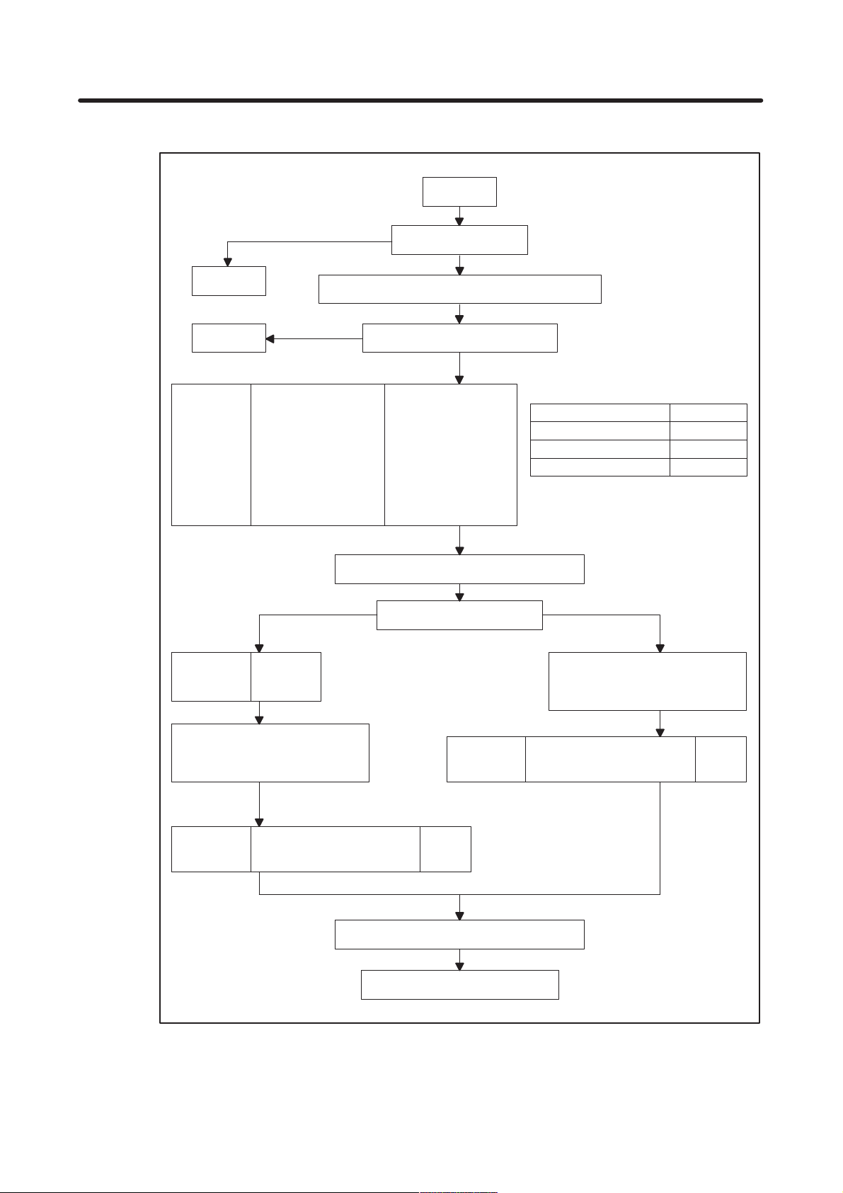
[Flowchart for servo parameter initialization]
Serial pulse coder C
Setting 3
Setting2 Least input increment 0.1 m ?
1874
1806
1820
1879
1896
Setting 1
Type of pulse coder ?
Turn on power to NC in emergency stop state
YES
NO
Initialization bit
Motor number No. 39 and later
AMR
CMR
Move direction
Reference counter
bit1=0,bit0=0No. 1804
See the table shown
at the right.
111 (CCW)
-111 (CW)
Serial pulse coder A or B
Motor
AC5-0
AC3-0S, 4-0S
Other than the above
B–62560E/03
AMR setting
AMR
10000010
00000011
00000000
Turn off the power, then turn it on again
Close loop
No. 1807
1815
Set fiexible feed gear :
1977 (N) Numerator of DMR
1978 (M) Denominator of DMR
1891
bit3=1
bit1=1
Number of speed pulses
Number of position pulses Ns
Turn off the power, then turn it on again
Type of machine system ?
1891
Ns: Number of feedback
8192No. 1876
pulses per motor
revolution sent from
the scale
Semi-closed loop
Set fiexible feed gear :
1977 (N) Numerator of DMR
1978 (M) Denominator of DMR
Number of speed pulses
Number of position pulses
8192No. 1876
12500
Completion of parameter setting
– 8 –
Page 17
B–62560E/03 2. SETTING PARAMETERS
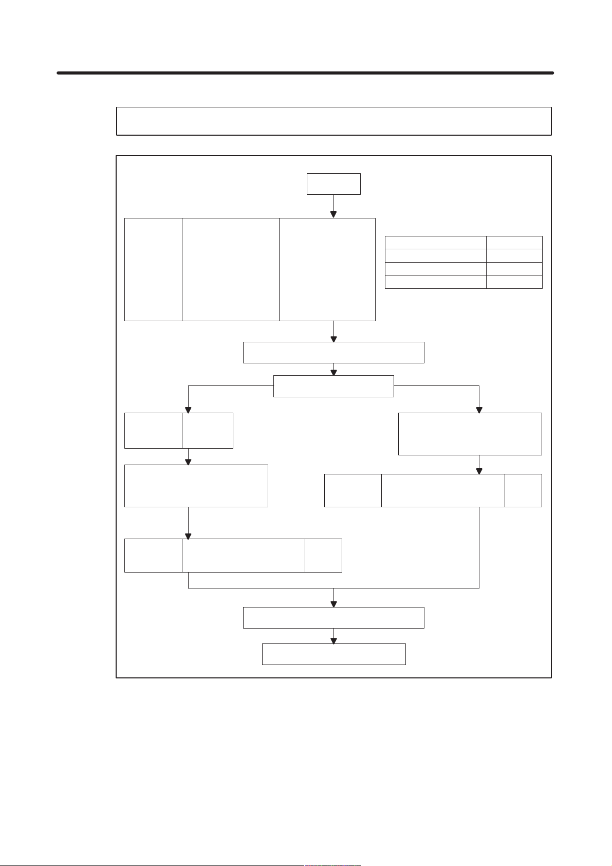
[Flowchart for setting when serial pulse coder A or B is used with a least input increment of 0.1µm]
NOTE An optional parameter for 0.1µm control is required.
Setting 2
Initialization bit
1874
1806
1820
1879
1896
No. 1807
1815
Set fiexible feed gear :
1977 (N) Numerator of DMR
1978 (M) Denominator of DMR
Motor number No. 39 and later
AMR
CMR
Move direction
Reference counter
Turn off the power, then turn it on again
Close loop
bit3=1
bit1=1
bit1=0,bit0=0No. 1804
See the table shown
at the right.
111 (CCW)
-111 (CW)
Type of machine system ?
1891
AMR setting
Motor
AC5-0
AC3-0S, 4-0S
Other than the above
Semi-closed loop
Set fiexible feed gear :
1977 (N) Numerator of DMR
1978 (M) Denominator of DMR
Number of speed pulses
Number of position pulses
AMR
10000010
00000011
00000000
819No. 1876
1250
1891
Number of speed pulses
Number of position pulses Ns/10
Turn off the power, then turn it on again
Completion of parameter setting
8192No. 1876
– 9 –
Ns: Number of feedback
pulses per motor
revolution sent from
the scale
Page 18
2. SETTING PARAMETERS
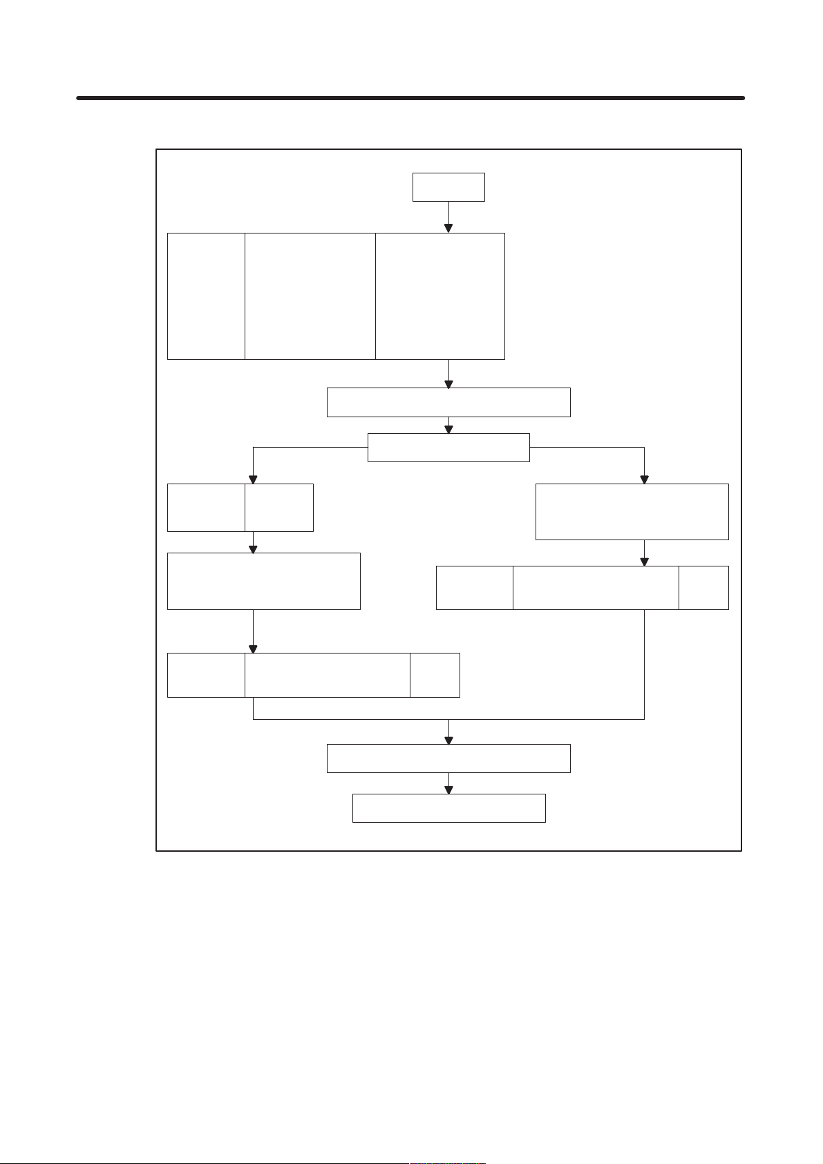
[Flowchart for setting when serial pulse coder C is used with a least input increment of 0.1µm]
B–62560E/03
Setting 3
Initialization bit
1874
1806
1820
1879
1896
No. 1807
1815
Set fiexible feed gear :
1977 (N) Numerator of DMR
1978 (M) Denominator of DMR
Motor number No. 39 and later
AMR
CMR
Move direction
Reference counter
Turn off the power, then turn it on again
Close loop
bit3=1
bit1=1
bit1=0,bit0=0No. 1804
00000000
111 (CCW)
-111 (CW)
Type of machine system ?
1891
Semi-closed loop
Set fiexible feed gear :
1977 (N) Numerator of DMR
1978 (M) Denominator of DMR
Number of speed pulses
Number of position pulses
4000No. 1876
4000
1891
Number of speed pulses
Number of position pulses Ns/10
Turn off the power, then turn it on again
Completion of parameter setting
4000No. 1876
Ns: Number of feedback
pulses per motor
revolution sent from
the scale
– 10 –
Page 19

B–62560E/03 2. SETTING PARAMETERS
[Setting the flexible feed gear]
When using a motor with a serial pulse coder, be sure to use the flexible feed gear for DMR setting.
An alarm is issued when the flexible feed gear is not used.
(Serial pulse coder A or B)
Numerator of DMR (No. 1977) Number of position feedback pulses per motor revolution
Denominator of DMR (No. 1978) 1,000,000
NOTE 1 The maximum specifiable number is 32767 for both the numerator and denominator. So,
reduce the above fraction to its lowest terms.
NOTE 2 When the T Series motor (serial pulse coder B) is used, the numerator of DMR (No. 1977) must
not be greater than 250,000, and the denominator of DMR (No. 1978) must be 1,000,000.
NOTE 3 Make sure the numerator <denominator.
Whenthenumeraor > denominator, an alarm is issued.
(Serial pulse coder C)
Numerator of DMR (No. 1977) Number of position feedback pulses per motor revolution
Denominator of DMR (No. 1978) 40,000
NOTE The maximum specifiable number is 32767 for both the numerator and denominator. So,
reduce the above fraction to its lowest terms.
=
=
(Closed loop)
Numerator of DMR (No. 1977) Number of position feedback pulses per motor revolution
Denominator of DMR (No. 1978) Number of pulse per encoder revolution
NOTE The maximum specifiable number is 32767 for both the numerator and denominator. So,
reduce the above fraction to its lowest terms.
=
– 11 –
Page 20

2. SETTING PARAMETERS
2.5 Compatibility of Parameters with the Series
15–MA, –TA, –TTA, –MF, –TF, and –TTF
1) For the above models, there were parameters for which the increment system used increased by a factor
of ten when the high–resolution detector interface was used (when PLC01, a bit of parameter No. 1804
is set to 1). However, for the Series 15–MB, –TB, –TTB, –MFB, –TFB, and –TTFB, the units remain the
same.
The following parameters for the models that used the high–resolution detection interface are no longer
compatible. For the Series 15–MB, –TB, –TTB, –MFB, –TFB, and –TTFB, be sure to specify the settings
for the following parameters with values ten–times larger than the original settings.
–– Parameters
1410, 1411, 1421, 1423, 1424, 1425, 1426, 1427, 1428
1451, 1452, 1453, 1454, 1455, 1456, 1457, 1458, 1459, 1460, 1461
1621, 1623, 1625, 1627, 1629
1827, 1828, 1829, 1830, 1832, 1837, 1850, 1896
7211, 7212, 7213, 7214, 7311, 7312, 7313
2) For the above models, there where parameters for which the increment system used increased by a factor
of ten when a maximum feedrate of 12 to 24 m per minute was used (when F24, a bit of parameter No.
1804, is set to 1). However, for the Series 15–MB, –TB, –TTB, –MFB, –TFB, and –TTFB, the units remain
the same.
The following parameters for the models that used the high–resolution detector interface are no longer
compatible. For the Series 15–MB, –TB, –TTB, –MFB, –TFB, and –TTFB, be sure to specify the settings
for the following parameters with values ten–times larger than the original settings.
–– parameters
1420, 1422
B–62560E/03
– 12 –
Page 21

B–62560E/03 3. PUNCHING PARAMETER TAPE
3. PUNCHING PARAMETER TAPE
3.1 Punching All Parameters
1 Connect a punch unit to the input/output interface.
2 Set the EDIT mode.
3 Press the SERVICE soft key, then press the PARAM soft key, or press the SERVICE hard key several
times. The parameter screen is displayed.
4 Press the PUNCH soft key, then press the ALL soft key. All the parameters are punched.
3.2 Punching Parameters Other Than Pitch Error Compensation
1 Connect a punch unit to the input/output interface.
2 Set the EDIT mode.
3 Press the SERVICE soft key, then press the PARAM soft key, or press the SERVICE hard key several
times. The parameter screen is displayed.
4 Press the PUNCH soft key, then press the P ARAM soft key. Parameters other than pitch error compensa-
tion are punched.
3.3 Punching Pitch Error Compensation Data
1 Connect a punch unit to the input/output interface.
2 Set the EDIT mode.
3 Press the SERVICE soft key , then press the PITCH soft key , or press the SERVICE hard key several times.
The pitch error compensation data screen is displayed.
4 Press the PUNCH soft key, then press the PITCH soft key. Pitch error compensation data is punched.
– 13 –
Page 22

4. DESCRIPTION OF PARAMETERS
4. DESCRIPTION OF PARAMETERS
Parameters are classified according to functions.
4.1 Parameters Related to Settings (Parameter Nos. 0000–0032) 16. . . . . . . . . . . . . . . . . . . . . . . . . . . . . .
4.2 Parameters Related to Timers (Parameter Nos. 0100–0119) 23. . . . . . . . . . . . . . . . . . . . . . . . . . . . . . .
4.3 Parameters Related to Axis Control (Parameter Nos. 1000–1059) 27. . . . . . . . . . . . . . . . . . . . . . . . . .
4.4 Parameters Related to Chopping (Parameter Nos. 1191–1197) 45. . . . . . . . . . . . . . . . . . . . . . . . . . . . .
4.5 Parameters Related to Coordinate Systems (Parameter Nos. 1200–1260) 47. . . . . . . . . . . . . . . . . . .
4.6 Parameters Related to Feedrate (Parameter Nos. 1400–1494) 50. . . . . . . . . . . . . . . . . . . . . . . . . . . . .
4.7 Parameters Related to Screen for Specifying High–Speed and High–Precision Machining
(Parameter Nos. 1517–1518) 65. . . . . . . . . . . . . . . . . . . . . . . . . . . . . . . . . . . . . . . . . . . . . . . . . . . . . . . . . .
4.8 Parameters Related to Acceleration/Deceleration Control (Parameter Nos. 1600–1653) 66. . . . . . . .
4.9 Parameters Related to Servo (Parameter Nos. 1800–1999) 76. . . . . . . . . . . . . . . . . . . . . . . . . . . . . . . .
4.10 Tandem Control 106. . . . . . . . . . . . . . . . . . . . . . . . . . . . . . . . . . . . . . . . . . . . . . . . . . . . . . . . . . . . . . . . . . . . .
4.1 1 Parameters Related to DI/DO (Parameter Nos. 2000–2052) 112. . . . . . . . . . . . . . . . . . . . . . . . . . . . . . .
4.12 Parameters Related to CRT/MDI and Editing (Parameter Nos. 2200–2388) 124. . . . . . . . . . . . . . . . . .
4.13 Parameters Related to Program (Parameter Nos. 2400–2900) 142. . . . . . . . . . . . . . . . . . . . . . . . . . . . .
4.14 Parameters Related to Serial Spindle Output and Cs Contour Control Function
(Parameter Nos. 3000–3303) 156. . . . . . . . . . . . . . . . . . . . . . . . . . . . . . . . . . . . . . . . . . . . . . . . . . . . . . . . . .
4.15 Parameters Related to Waveform Diagnosis Function (Parameter Nos. 4640–4646) 189. . . . . . . . . . .
4.16 Parameters Related to Graphic Display (Parameter Nos. 4821–4883) 190. . . . . . . . . . . . . . . . . . . . . . .
4.17 Parameters Related to Reader/Punch Interfaces (Parameter Nos. 5000–5162) 194. . . . . . . . . . . . . . .
4.18 Parameters Related to Stroke Limit (Parameter Nos. 5200–5248) 205. . . . . . . . . . . . . . . . . . . . . . . . . . .
4.19 Parameters Related to Position Switching Function (Parameter Nos. 5200–5299) 214. . . . . . . . . . . . .
4.20 Parameters Related to Reference Marks (Parameter Nos. 1008, 5226–5227) 217. . . . . . . . . . . . . . . .
4.21 Parameters Related to Pitch Error Compensation (Parameter Nos. 5420–5433) 220. . . . . . . . . . . . . .
4.22 Parameters Related to Gradient Compensation
(Valid only with the Series 15–M and Series 15–T)(Parameter Nos. 5461–5474) 237. . . . . . . . . . . . . .
4.23 Parameters Related to Straightness Compensation
(Valid only with the Series 15–M and Series 15–T)(Parameter Nos. 5481–5574) 239. . . . . . . . . . . . . .
4.24 Parameters Related to Spindle Control (Parameter Nos. 5600–5820) 250. . . . . . . . . . . . . . . . . . . . . . .
4.25 Parameters Related to Rigid Tapping with the Series 15–TT
(Parameter Nos. 3000–3213, 5610–5955) 282. . . . . . . . . . . . . . . . . . . . . . . . . . . . . . . . . . . . . . . . . . . . . . .
4.26 Parameters Related to the Electronic Gear Box (EGB) (Parameter Nos. 5990–5998) 290. . . . . . . . . .
4.27 Parameters Related to T ool Of fsets (Parameter Nos. 6000–6121) 295. . . . . . . . . . . . . . . . . . . . . . . . . . .
4.28 Three–Dimensional Cutter Compensation (Supplement)(Parameter Nos. 6080–6115) 307. . . . . . . . .
4.29 Parameters Related to Cylindrical Interpolation Cutting Point Compensation
(Parameter Nos. 6004–6113) 312. . . . . . . . . . . . . . . . . . . . . . . . . . . . . . . . . . . . . . . . . . . . . . . . . . . . . . . . . .
4.30 Parameters Related to Canned Cycles (Parameter Nos. 6200–6240) 314. . . . . . . . . . . . . . . . . . . . . . .
4.31 Parameters Related to Scaling and Coordinate Rotation (Parameters Nos. 6400–6421) 322. . . . . . . .
4.32 Parameters Related to Automatic Corner Override (Parameter Nos. 6610–6614) 324. . . . . . . . . . . . . .
4.33 Parameters Related to Automatic Feedrate Control Using Involute Interpolation
(Parameter Nos. 6620–6634) 327. . . . . . . . . . . . . . . . . . . . . . . . . . . . . . . . . . . . . . . . . . . . . . . . . . . . . . . . . .
4.34 Parameters Related to Uni–Directional Positioning (Parameter No. 6820) 329. . . . . . . . . . . . . . . . . . .
4.35 Parameters Related to Custom Macros (Parameter Nos. 7000–7089) 330. . . . . . . . . . . . . . . . . . . . . . .
4.36 Parameters Related to Restarting Programs and Blocks and T ool Retraction and Recovery
(Parameter No. 71 10) 338. . . . . . . . . . . . . . . . . . . . . . . . . . . . . . . . . . . . . . . . . . . . . . . . . . . . . . . . . . . . . . . .
4.37 Parameters Related to Skip Function (Parameter Nos. 7200–7220) 339. . . . . . . . . . . . . . . . . . . . . . . . .
4.38 Parameters Related to Automatic Tool Compensation (for the Series 15–T only) and
Automatic Tool Length Measurement (for the Series 15–M only)(Parameter Nos. 7300–7333) 344. .
B–62560E/03
– 14 –
Page 23

B–62560E/03 4. DESCRIPTION OF PARAMETERS
4.39 Parameters Related to Tool Life Management (Parameter Nos. 7400–7442) 346. . . . . . . . . . . . . . . . .
4.40 Parameters Related to Turret Axis Control (Parameter Nos. 7500–7536) 349. . . . . . . . . . . . . . . . . . . . .
4.41 Parameters Related to 3–Dimensional Handle Feel for 15–M (Parameter Nos. 7537–7558) 352. . . .
4.42 Parameters Related to 15–TT Three–Dimensional Handle Feed
(Parameter Nos. 7546–7759, 1000) 358. . . . . . . . . . . . . . . . . . . . . . . . . . . . . . . . . . . . . . . . . . . . . . . . . . . .
4.43 Parameters Related to 15–TT T ool Length Compensation Along the Tool Axis
(Parameter Nos. 6001–7752) 366. . . . . . . . . . . . . . . . . . . . . . . . . . . . . . . . . . . . . . . . . . . . . . . . . . . . . . . . . .
4.44 Parameters Related to Designation Direction T ool Length Compensation
(Parameter No. 771 1) 371. . . . . . . . . . . . . . . . . . . . . . . . . . . . . . . . . . . . . . . . . . . . . . . . . . . . . . . . . . . . . . . .
4.45 Parameter Related to Upgraded 5–Axis Control Compensation (Parameter Nos. 7559–7614) 372. . .
4.46 Parameters Related to High–Precision Contour Control 373. . . . . . . . . . . . . . . . . . . . . . . . . . . . . . . . . . .
4.47 Parameters Related to High–Precision Contour Control Based on a 64–Bit RISC Processor
(Parameter Nos. 1009–8481) 377. . . . . . . . . . . . . . . . . . . . . . . . . . . . . . . . . . . . . . . . . . . . . . . . . . . . . . . . . .
4.48 Other Parameters (Parameter Nos. 7600–7799) 383. . . . . . . . . . . . . . . . . . . . . . . . . . . . . . . . . . . . . . . . .
4.49 Parameters Related to Maintenance (Parameter Nos. 8000–8010) 402. . . . . . . . . . . . . . . . . . . . . . . . . .
4.50 DNC Operation with the Remote Buffer 403. . . . . . . . . . . . . . . . . . . . . . . . . . . . . . . . . . . . . . . . . . . . . . . . .
– 15 –
Page 24

4. DESCRIPTION OF PARAMETERS
4.1 Parameters Related to Settings
#7 #6 #5 #4 #3 #2 #1 #0
0000 RMTDG DNC EIA NCR ISP CTV TVC
Setting input
Data type : Bit
TVC Specifies whether TV check is performed.
0 : Do not perform.
1 : Perform.
CTV Specifies whether characters are counted for TV check during control out.
0 : Count.
1 : Do not count.
ISP Specifies whether ISO codes contain a parity bit.
0 : Contain parity bit.
1 : Do not contain parity bit.
(A parity bit is located at channel 8 in a punched tape in the ISO code.)
NCR Specifies how to punch an EOB (end–of–block) code when using ISO codes.
0 : Punch LF CR CR.
1 : Punch LF.
EIA Specifies the code system to use for punch codes.
0 : ISO code
1 : EIA code
DNC Specifies conditions for DNC operation with the remote buffer.
0 : Enable high–speed distribution if high–speed distribution conditions are satisfied.
1 : Perform normal distribution.
RMTDGSpecifies whether to perform remote diagnosis.
0 : Not performed.
1 : Performed.
B–62560E/03
#7 #6 #5 #4 #3 #2 #1 #0
0003 XTST KGRG NKGRH
Setting input
Data type : Bit
NKGRHSpecifies whether to stop drawing graphic A when the screen is switched to another one during
drawing.
0 : Stop.
1 : Do not stop.
KGRG In the graphic guidance function.
0 : Graphics are drawn for guidance.
1 : Graphics are not drawn for guidance.
NOTE This function is not available in Series 15–MB(MA2).
XTST Specifies how data is obtained for the internal investigation function used when diagnostic guidance
is activated.
0 : Read specified data automatically.
1 : Use data input by the operator as the function value.
– 16 –
Page 25

B–62560E/03 4. DESCRIPTION OF PARAMETERS
NOTE When this bit is set to 1, the user can set the internal investigation function to any value. This
allows the user to check and debug the knowledge base.
#7 #6 #5 #4 #3 #2 #1 #0
0010 SB0 SBC SBM SB8 SB7 GRPBG SQN INI
Setting input
Data type : Bit
INI Specifies whether the increment system is metric or in inches.
0 : Metric input
1 : Inch input
SQN Specifies whether sequence numbers are automatically inserted.
0 : Do not insert.
1 : Insert.
GRPBGSpecifies whether to display an graphic display or background graphic display.
0 : Graphic Display
1 : Background Graphic Display
SB7 Specifies whether to stop after each block of custom macro statements in programs 07000 to 07999.
0 : Do not stop after each block.
1 : Stop after each block. (Used to debug custom macros.)
SB8 Specifies whether to stop after each block of custom macro statements in programs 08000 to 08999.
0 : Do not stop after each block.
1 : Stop after each block. (Used to debug custom macros.)
SBM Specifies whether to stop after each block of custom macro statements in any program.
0 : Do not stop after each block. (However, when stopping is specified in SB7 or SB8, stopping will
occur in programs affected by these parameters.)
1 : Stop after each block. (Used to debug custom macros.)
SBC Specifies whether to stop after each block in hole–machining canned cycles (Not used in the Series
15–TT).
0 : Do not stop after each block.
1 : Stop after each block. (Used when trouble occurs with canned cycles.)
SBO Specifies whether to stop after each block automatically generated in the NC for cutter or tool tip
radius compensation.
0 : Do not stop after each block.
1 : Stop after each block. (Used when trouble occurs with cutter or tool tip radius compensation.)
– 17 –
Page 26

4. DESCRIPTION OF PARAMETERS
#7 #6 #5 #4 #3 #2 #1 #0
0011 G50 HSO NOT TIM HSDLD ND8 NE8
Setting input
Data type : Bit
NE8 Specifies whether to permit editing of 08000 to 08999 programs.
0 : Permit editing.
1 : Do not permit editing.
ND8 Specifies whether to display the program being executed on the CRT for programs 08000 to 08999.
0 : Display program being executed.
1 : Do not display program being executed.
HSDLD Specifies whether the high–speed part program registration function is used.
0 : Not used.
1 : Used.
Normally, set this bit to 0.
When there is no need to display custom macros or other programs being executed, set this parameter to 1.
This function speeds up the registration of part programs in the foreground mode (EDIT mode). In the back-
ground mode, part programs are registered at normal speed.
If the power is disconnected during registration of part programs, the system operates as follows when the pow-
er is restored:
(1) Displays “CLEAR PROGRAM FILE (HSPD DLOAD)” on the CRT screen.
(2) Clears all part programs (including high–speed machining programs).
(3) Halts when the IPL monitor screen is displayed.
To restart the system, select “6 END IPL” by entering 6, or turn the power off then on again.
When part programs are being registered, they are not displayed.
When part programs are being registered, screens cannot be updated in some cases.
TIM Specifies the information displayed on the screen for the program No. and name directory.
0 : Display program No., name, and memory used.
1 : Display program No., name, and processing time.
NOT Specifies whether to use tool Nos. to specify output of tool pot Nos. and tool offsets.
0 : Use tool Nos. (H/D codes cannot be used to specify tool length compensation and cutter com-
pensation).
1 : Do not use tool Nos. (H/D codes can be used to specify tool length compensation and cutter com-
pensation Neither entering H or D codes in the tool life management function nor specifying H99
codes or D99 codes can be performed.).
HSO Specifies operation performed when the G10.3 L1/L2 command is used.
0 : Skip the program up to G11.3 and execute high–speed machining using previously registered
data (call operation mode).
1 : Convert commands up to G11.3 into high–speed machining data, then register the data and use
it to perform high–speed machining (register operation mode).
G50 Specifies whether to allow use of code G50 (G92 in G code system B and C; for specifying the coordi-
nate system) when using the Series 15–T.
0 : Allow G50 (G92 in G code system B and C) to be used in a program command
1 : Do not allow G50 (G92 in G code system B and C) to be used in a program command. If G50 is
used, a P/S alarm will be generated.
Set this parameter to 1 when the coordinate system is set using a tool geometry offset (instead of G50).
In this case, an alarm will be generated if G50 is used inadvertently .
B–62560E/03
– 18 –
Page 27

B–62560E/03 4. DESCRIPTION OF PARAMETERS
#7 #6 #5 #4 #3 #2 #1 #0
0012 RMVx SCLx MIRx
Setting input
Data type : Bit axis
MIRx For each axis, specifies whether to use its mirror image.
0 : Do not use mirror image (normal).
1 : Use mirror image (mirror).
SCLx For each axis, specifies whether scaling is used (only for the Series 15–M)
0 : Use scaling.
1 : Do not use scaling.
RMVxFor each axis, specifies whether to detach the shaft corresponding to the control axis.
0 : Do not detach.
1 : Detach.
Effective when RMBx, a bit of parameter No. 1005, is set to 1.
#7 #6 #5 #4 #3 #2 #1 #0
0013 DSYS HDIO HKEY NDSP PCMN
Setting input
Data type : Bit
PCMN Specifies whether to display the PMC user screen (PCMDI) directly with the PMC/CNC key.
0 : Do not display the screen.
1 : Display the screen.
NDSP Specifies whether to display multiple subscreens on the PMC screen.
0 : Display multiple subscreens.
1 : Do not display multiple subscreens.
HKEY Specifies whether to store the history of key operations with the operation history function key.
0 : Do not store the history.
1 : Store the history.
HDIO Specifies whether to store the history of DI/DO with the operation history function key.
0 : Do not store the history.
1 : Store the history.
DSYS Specifies whether to display the system history screen.
0 : Do not display the screen.
1 : Display the screen.
– 19 –
Page 28

4. DESCRIPTION OF PARAMETERS
#7 #6 #5 #4 #3 #2 #1 #0
0014 HD2 BDSP FMST
Setting input
Data type : Bit
FMST Specifies whether to output alarm OH001, ”FAN MOTOR STOP.”
0 : Output the alarm.
1 : Do not display the alarm.
BDSP Specifies the units used for the file sizes in the disk directory display.
0 : Meters (metric input) or feet (inch input)
1 : Bytes
HD2 Specifies whether the size of one file can exceed 2000 m when using a floppy cassette, the PRO
GRAM FILE Mate, HANDY FILE, or FA card.
0 : Within 2000 m
1 : Can exceed 2000 m
#7 #6 #5 #4 #3 #2 #1 #0
0015 KYON HION HPOF SPOF SVOF
B–62560E/03
Parameter input
Data type : Bit
SVOF Specifies whether to display the servo screen.
0 : Display the servo screen.
1 : Do not display the servo screen.
SPOF Specifies whether to display the spindle screen.
0 : Display the spindle screen.
1 : Do not display the spindle screen.
HPOF Specifies whether to display the screen for high–precision contour control.
0 : Display the screen.
1 : Do not display the screen.
HION
0 :The operation history is not displayed. (Note that the alarm history is still displayed. )
1 : The operation history is displayed.
KYON
0 : [ERASE] key on the operation history screen is disabled.
1 : [ERASE] key on the operation history screen is enabled.
NOTE On the operation history screen, using the erase key can erase:
– Operation history data
– Alarm history data
– 20 –
Page 29

B–62560E/03 4. DESCRIPTION OF PARAMETERS
0016 Screen saver start time
Setting entry
Data type : Byte
Data unit : Minute
Data range : 0 to 127
When the operator does not operate the keyboard for the period specified in this parameter, the saver screen
is displayed. When 0 is specified, the screen saver function is disabled.
NOTE This function is not available in Series 15–MB(MA2).
0020 Interface No. of input device for foreground
Setting input
Data type : Byte
Assignment of input device numbers for foreground
0 : Reader connected to JD5A of main CPU board
1 : Reader connected to JD5A of main CPU board (Settings 0 and 1 are identical.)
2 : Reader connected to JD5B of main CPU board
3 : Reader connected to JD5J of the subboard
4 : DNC1
9 : PMC
10: Remote buffer
13: Reader connected to JD6D of the subboard
14: Data Server
15: MMC DNC operation interface
16: MMC upload/download interface
Perform system reset after setting this parameter.
0021 Interface No. of output device for foreground
Setting input
Data type : Byte
Assignment of output device numbers for foreground
1 : Punch connected to JD5A of main CPU board
2 : Punch connected to JD5B of main CPU board
3 : Punch connected to JD5J of the subboard
4 : DNC1
9 : PMC
10: Remote buffer
13: Punch connected to JD6D of the subboard
14: Data Server
15: MMC DNC operation interface
16: MMC upload/download interface
Perform system reset after setting this parameter.
– 21 –
Page 30

4. DESCRIPTION OF PARAMETERS
0022 Interface No. of input device for background
Setting input
Data type : Byte
Assignment of input device numbers for background
0 : Reader connected to JD5A of main CPU board
1 : Reader connected to JD5A of main CPU board (Settings 0 and 1 are identical.)
2 : Reader connected to JD5B of main CPU board
3 : Reader connected to JD5J of the subboard
4 : DNC1
9 : PMC
10: Remote buffer
13: Reader connected to JD6D of the subboard
14: Data Server
15: MMC DNC operation interface
16: MMC upload/download interface
Perform system reset after setting this parameter.
B–62560E/03
0023 Interface No. of output device for background
Setting input
Data type : Byte
Assignment of output device numbers for background
1 : Punch connected to JD5A of main CPU board
2 : Punch connected to JD5B of main CPU board
3 : Punch connected to JD5J of the subboard
4 : DNC1
9 : PMC
10: Remote buffer
13: Punch connected to JD6D of the subboard
14: Data Server
15: MMC DNC operation interface
16: MMC upload/download interface
Perform system reset after setting this parameter.
0031 Initial value used for automatic setting of sequence Nos.
Setting input
Data type : Two words
Valid range : 0 to 99999
0032 Increment used for automatic setting of sequence Nos.
Setting input
Data type : Two words
Valid range : 0 to 99999
– 22 –
Page 31

B–62560E/03 4. DESCRIPTION OF PARAMETERS
4.2 Parameters Related to Timers
0100 Timer 1 (time accumulated since power–on)
Parameter input
Data type : Two words
Unit : Minutes
Valid range : 0 to 99999999
Timer 1 : Sets and displays the time accumulated since power–on.
0101 Timer 2 (time accumulated during automatic operation)
Setting input (For the Series 15–TT, this parameter is for the first tool post.)
Data type : Two words
Unit : Milliseconds
Valid range : 0 to 60000
Timer 2 : Sets and displays the time accumulated during automatic operation.
0102 Timer 3 (time accumulated during automatic operation)
Setting input (For the Series 15–TT, this parameter is for the first tool post.)
Data type : Two words
Unit : Minutes
Valid range : 0 to 99999999
Timer 3 : Sets and displays the time accumulated during automatic operation.
0103 Timer 4 (time accumulated during cutting)
Setting input (For the Series 15–TT, this parameter is for the first tool post.)
Data type : Two words
Unit : Milliseconds
Valid range : 0 to 60000
Timer 4 : Sets and displays the time accumulated during cutting.
0104 Timer 5 (time accumulated during cutting)
Setting input (For the Series 15–TT, this parameter is for the first tool post.)
Data type : Two words
Unit : Minutes
Valid range : 0 to 99999999
Timer 5 : Sets and displays the time accumulated during cutting.
– 23 –
Page 32

4. DESCRIPTION OF PARAMETERS
B–62560E/03
0105
Setting input
Data type : Two words
Unit : Milliseconds
Valid range : 0 to 60000
Timer 6 : Sets and displays the time accumulated while the TMRON signal is on.
0106
Setting input
Data type : Two words
Unit : Minutes
Valid range : 0 to 99999999
Timer 7 : Sets and displays the time accumulated while the TMRON signal is on.
Timer 6 (time accumulated while general–purpose integrating
meter activating signal TMRON is on)
There is an integrating meter in the control unit that is activated by an input signal from the machine. This integrating meter can be preset by this parameter.
Timer 7 (time accumulated while general–purpose integrating
meter activating signal TMRON is on)
There is an integrating meter in the controller that is activated by an input signal from the machine side. This integrating meter can be preset by this parameter.
0107 Total number of parts machined
Setting input
Data type : Two words
Unit : Number of parts
Valid range : 0 to 99999
Sets and displays the total number of parts machined.
For the Series 15–TT, this parameter applies to the first spindle.
0108 Total number of parts
Setting input
Data type : Two words
Unit : Number of parts
Valid range : 0 to 99999999
For the Series 15–TT, this parameter indicates the total number of parts for the first spindle.
0109 Number of parts required
Setting input
Data type : Two words
Unit : Number of parts
Valid range : 0 to 99999999
When the total number of machined parts (parameter No. 0107) exceeds the number of parts
required, a signal is output to the machine.
For the Series 15–TT , this parameter indicates the total number of parts machined by the first
spindle.
– 24 –
Page 33

B–62560E/03 4. DESCRIPTION OF PARAMETERS
0111
Setting input (only for the Series 15–TT)
Data type : Two words
Unit : Milliseconds
Valid range : 0 to 60000
Timer 8 : Sets and displays the time accumulated during automatic operation of the second tool post.
0112
Setting input (only for the Series 15–TT)
Data type : Two words
Unit : Minutes
Valid range : 0 to 99999999
Timer 9 : Sets and displays the time accumulated during automatic operation of the second tool post.
0113 T imer 10 (time accumulating during cutting with the 2nd tool post)
Setting input (only for the Series 15–TT)
Data type : Two words
Unit : Milliseconds
Valid range : 0 to 60000
Timer 10 : Sets and displays the time accumulated during cutting with the second tool post.
Timer 8 (time accumulated during automatic operation of the
2nd tool post)
Timer 9 (time accumulated during automatic operation of the
2nd tool post)
0114 T imer 11 (time accumulating during cutting with the 2nd tool post)
Setting input (only for the Series 15–TT)
Data type : Two words
Unit : Minutes
Valid range : 0 to 99999999
Timer 11 : Sets and displays the time accumulated during cutting with the second tool post.
0117 Total number of parts machined (with the 2nd spindle)
Setting input (only for the Series 15–TT)
Data type : Two words
Unit : Number of parts
Valid range : 0 to 99999999
This parameter indicates the total number of parts machined by the second spindle.
– 25 –
Page 34

4. DESCRIPTION OF PARAMETERS
0118 Total number of parts machined (with the 2nd spindle)
Setting input (only for the Series 15–TT)
Data type : Two words
Unit : Number of parts
Valid range : 0 to 99999999
This parameter indicates the total number of parts machined by the second spindle.
0119 Number of parts required to be machined (with the 2nd spindle)
Setting input (only for the Series 15–TT)
Data type : Two words
Unit : Number of parts
Valid range : 0 to 99999999
This parameter indicates the total number required to be machined by the second spindle.
B–62560E/03
– 26 –
Page 35

B–62560E/03 4. DESCRIPTION OF PARAMETERS
4.3 Parameters Related to Axis Control
#7 #6 #5 #4 #3 #2 #1 #0
1000 HLB EMI EHM FPI XIK CSZ CIP
Parameter input
Data type : Bit
CIP Specifies whether to perform an in–position check after deceleration.
0 : Do not perform in–position check (during deceleration, wait until the feedrate reaches zero before
executing next block).
1 : Perform in–position check (during deceleration, wait until the feedrate reaches zero and then also
confirm the machine reaches the specified position before executing next block).
CSZ Specifies whether to enable the in–position check signal (*CSMZ)
0 : Disable
1 : Enable
XIK When axis interlock is applied during non–linear interpolation positioning (when LRP , a bit of parame-
ter No. 1400 is se to 0), specifies whether to stop only the axis to which interlock was applied or all axes.
0 : Stop axis to which interlock was applied. (Other axes continue operation.)
1 : Stop all axes.
FPI Specifies whether to perform an in–position check at the temporary stop–point in G60 mode.
0 : Do not perform in–position check.
1 : Perform in–position check.
EHM Specifies conditions when handle interruption is valid.
0 : When in G01, G02, or G03 mode, handle interruption is valid during automatic operation startup,
stopping, and resting.
1 : Handle interruption is only valid for G01, G02, and G03 blocks during automatic operation startup.
EMI Specifies validity of manual interrupts and manual setup operations during simultaneous
manual–automatic operation.
0 : Manual interrupts are invalid and manual setup operations are valid.
1 : Manual interrupts and manual setup operations are valid.
HLB Specifies the rotation axes during 3–dimensional handle feed when the axis of the tool is on the Z–axis
0 : Axes A and C.
1 : Axes B and C.
NOTE Set TLAX and SLAB, bits of parameter No. 7550 to 0. If either of these bits is set to 1, HLB will
be ignored.
– 27 –
Page 36

4. DESCRIPTION OF PARAMETERS
#7 #6 #5 #4 #3 #2 #1 #0
1001 CHPX PED PGDM IMCW NCOD RPC
Parameter input (only for the Series 15–M)
Data type : Bit
RPC Specifies whether the axes are switched when a reference position return (G29) is performed.
0 : Axes are switched.
1 : Axes are switched.
NCOD Specifies the conditions for calculating a spline when 0 x t x T.
0 : T = 1 for the first segment of the spline and T is the ratio of the chord of each consecutive segment
to the chord of the first segment.
Assuming that the specified point array is P
the following equations are satisfied:
T=P P/PP=1
T=P P/PP
……………
=Pn– Pn / P P
T
n–
1 : T = 1 for all segments.
IMCW Specifies the forward direction of one rotation axis of the two axes for which hypothetical axis control
is possible.
0 : Forward direction is counterclockwise.
1 : Forward direction is clockwise.
B–62560E/03
, P2, ..., Pn and T of each segment is T1, T2, ..., T
1
n–1
,
NOTE This function is not available in Series 15–MB(MA2).
PGDM Specifies whether the G code (G10.9) for selecting diameter or radius programming is valid for axis
commands in the program.
0 : Invalid.
1 : Valid.
PED Specifies whether to enable the external deceleration function in axis control by PMC.
0 : Disables the external deceleration function.
1 : Enables the external deceleration function.
CHPX Specifies whether the settings that specify the chopping axis and chopping rate can be set.
0 : Can be set.
1 : Cannot be set.
#7 #6 #5 #4 #3 #2 #1 #0
1002 DC2 DC4 ROPS INM
Parameter input
Data type : Bit
INM Specifies whether the detection unit for the linear axis of the machine is metric or in inches.
0 : Metric
1 : Inches
ROPSSpecifies which parameter enables or disables the roll–over function for a rotation axis.
0 : RDAx bit of parameter 1008
1 : RDA2x bit of parameter 1009
DC4 Specifies how to establish a reference position for a linear scale having reference marks.
0 : An absolute position is established by detecting three reference marks.
1 : An absolute position is established by detecting four reference marks.
– 28 –
Page 37

B–62560E/03 4. DESCRIPTION OF PARAMETERS
DC2 When the reference position establishment by the distance coded linear scale,
0 : Conforms to DC4.
1 : The axis moves until two reference marks are detected.
NOTE 1 When this parameter is set to 1, set the direction of scale zero in the parameter
(No.191 1#SCLPx) correctly.
NOTE 2 Even if DC2 is ”1”, the rotary axis (parameter No.1006#ROTx=1) follows DC4.
#7 #6 #5 #4 #3 #2 #1 #0
1004 PDSx DSPx ISDx IPRx ISFx ISRx
Parameter input
Data type : Bit
ISRx, ISFx, ISDx, ISEx (parameter No. 1009) Specify an increment system for each axis
ISEx Specifies an increment system for each axis in parameter No. 1009.
ISDx ISFx ISRx Least input increment, least command increment Abbr.
ISEx
0 0 0 0 0.001 mm, 0.001 deg, or 0.0001 inch IS–B
0 0 0 1 0.01 mm, 0.01 deg, or 0.001 inch IS–A
0 0 1 0 0.0001 mm, 0.0001 deg, or 0.00001 inch IS–C
0 1 0 0 0.00001 mm, 0.00001 deg, or 0.000001 inch IS–D
1 0 0 0 0.000001 mm, 0.000001 deg, or 0.0000001 inch IS–E
Always set the increment system of the spindle positioning (indexing) axis to 0.001 deg (IS–B).
NOTE When using the Series 15–TT, select the same increment system for those axes that have the
same axis name assigned with head 1/head 2.
IPRx Specifies whether to set the least input increment of each axis to ten times the least command incre-
ment.
0 : Do not set to ten times the least command increment.
1 : Set to ten times the least command increment.
When the above parameter is set to 1, the least input increments become as follows:
IS–A
IS–B 0.01 mm, 0.01 deg, or 0.001 inch
IS–C 0.001 mm, 0.001 deg, or 0.0001 inch
IS–D 0.0001 mm, 0.0001 deg, or 0.00001 inch
IS–E 0.00001 mm, 0.00001 deg, or 0.000001 inch
NOTE When IS–A is used as the increment system, the least input increment cannot be set to ten
times the least command increment.
DSPx Specifies whether to display axis positions on the position screen and other screens.
0 : Display axis positions.
1 : Do not display axis positions.
0.01 mm, 0.01 deg, or 0.001 inch
NOTE When using the electronic gear box function (EGB), specify 1 for the dummy axis of the EGB
to disable position display .
– 29 –
Page 38

4. DESCRIPTION OF PARAMETERS
This parameter is used to select whether the following screens are displayed:
Position, program check, operating monitor, tool of fset, and graphics screens
This parameter does not affect the axis display on the following screens:
Workpiece offset, parameter, diagnosis, and servo check screens
PDSx Specifies whether to display axis positions on the playback screen.
0 : Do not display axis positions.
1 : Display axis positions.
NOTE 1 This parameter is valid when the total number of controllable axis is six or more. Set
parameters to 1 which correspond to five axes of which the positions are displayed. However,
note that this parameter is ineffective when the NXT –AX and PRV –AX soft keys are displayed
on the playback screen.
NOTE 2 When increment system IS–D is selected, the maximum travel (largest value that can be
specified at once) for linear and circular interpolation is as follows:
No. of simultaneous
moving axis.
2 7500.00000 mm 750.000000 inch
3 6000.00000 mm 600.000000 inch
4 5300.00000 mm 500.000000 inch
5 4800.00000 mm 480.000000 inch
6 4300.00000 mm 430.000000 inch
B–62560E/03
Maximum travel
NOTE 3 Values specified when IS–D is selected
The unit of values for the following addresses are 0.00001 mm, 0.00001 deg, and 0.000001
inch. For example, if X1000 is specified (in the case of decimal point input), the resulting values
are X0.01 mm, X0.01 deg, and X0.001 inch.
T able 3 Basic address and command value range
Function
Dimension ward
Feedrate per
minute
Feedrate per
revolution thread
leading
NOTE 1 When inch input is used on a millimeter machine or metric input is used on an inch machine,
the command value range differs partially.
NOTE 2 When an arc radius is specified using R, it can be specified as "999999999 (nine digits).
Address Metric input Inch input
X, Y, Z, A, B, C,
U, V , W, I, J, K, R
F
F
±9999.99999
mm or deg
0.0001 to
10000 mm/min
0.0000001 to
5.0000000 mm/rev
±999.999999
inch or deg
0.00001 to
1000 inch/min
0.00000001 to
0.50000000
inch/rev
– 30 –
Page 39

B–62560E/03 4. DESCRIPTION OF PARAMETERS
#7 #6 #5 #4 #3 #2 #1 #0
1005 RMBx ZNGx EDMx EDPx PLZx ALZx ZRNx
Parameter input
Data type : Bit axis
ZRNx Specifies whether the reference position return function is provided for each axis.
0 : Provided
1 : Not provided
ALZx Specifies the method to use for automatic reference position return (G28).
0 : Return to reference position using positioning control (rapid traverse). If reference position return
has not been performed since power–on, it is performed using the same operation sequence as
for manual reference position return.
1 : Use the same operation sequence as for manual reference position return.
Usually , set this bit to 0.
PLZx Specifies the condition for presetting the work coordinate system when manual reference position
return is performed.
0 : Preset only when in reset state (e.g. OP signal is off).
1 : Always preset.
See ZNP in parameter No. 2402, which is common to all axes.
EDPx For each axis, specifies whether the external deceleration signal for the positive direction is valid
during cutting feed.
0 : Invalid
1 : Valid
EDMx For each axis, specifies whether the external deceleration signal for the negative direction is valid
during cutting feed.
0 : Invalid
1 : Valid
ZNGxSpecifies whether machine lock is valid for each axis.
0 : Invalid
1 : Valid
RMBx For each axis, specifies whether the control axis detach signal and setting input RMVx (parameter
No.0012) is valid.
0 : Invalid
1 : Valid
– 31 –
Page 40

4. DESCRIPTION OF PARAMETERS
#7 #6 #5 #4 #3 #2 #1 #0
1006 RTRx NDCx ZMIx DIAx ROPx ROSx ROTx
Parameter input
Data type : Bit axis
ROTx Specifies whether the axis requires inch/metric conversion.
0 : Axis requires inch/metric conversion (linear axis).
1 : Axis does not require inch/metric conversion (rotation axis).
ROSxSpecifies whether the machine coordinate system used for stroke check and automatic reference
position return is linear or rotational.
0 : Linear (linear axis)
1 : Rotation (rotation axis)
For a rotation axis, the machine coordinate system is normalized to 0 to 360 degrees. In this case,
automatic reference position return (G28, G30) is performed in the same direction as manual reference position return and the degree of rotation does not exceed 360 degrees. Also see the item on
parameter No. 1260.
ROPxSpecifies whether the machine coordinate system used to perform the retained pitch error compensa-
tion is linear or rotational.
0 : Linear (linear axis)
1 : Rotation (rotation axis)
When the coordinate system used is rotational, up to the angle which corresponds to one cycle of re-
tained pitch error compensation data can be specified. This allows pitch compensation to be performed for pitch compensation cycles of other than 360 degrees. Also see the item on parameter No.
5425.
DIAx Specifies whether movement along each axis is specified by diameter or radius.
0 : Specified by radius.
1 : Specified by diameter.
ZMIx Specifies the direction of manual reference position return.
0 : Positive direction
1 : Negative direction
NDCxSpecifies the normal direction control axis.
0 : Not normal direction control axis
1 : Normal direction control axis (only one axis can be specified as the normal direction control axis.)
RTRx Specifies whether retract operation is performed along an axis when the electronic gear box function
or functions for hobbing machines are used.
1 : Performed.
0 : Not performed.
B–62560E/03
#7 #6 #5 #4 #3 #2 #1 #0
1007 DOGx GRDx RINC RREL RG90 RSRV FAX
Data type : Bit axis
FAX Specifies whether the fixture ofset is valid for each axis.
0 : Invalid.
1 : Valid.
RSRV When an absolute command is executed (when RINC, a bit of parameter No. 1007 is set to 0), speci
fies whether the direction of rotation is determined by the sign of the value specified by the com-
mand.
0 : Not determined.
1 : Determined by command value (counterclockwise when value is positive and clockwise when
value is negative)
– 32 –
Page 41

B–62560E/03 4. DESCRIPTION OF PARAMETERS
RG90 Specifies the type of commands used for the multiple rotary control axes.
0 : Either absolute or incremental commands determined by G90 or G91 mode
1 : Absolute commands
RREL Specifies whether the current position of the multiple rotary control axes in the relative coordinate
system is displayed with the value rounded off within one rotation.
0 : Not performed.
1 : Performed.
RINC In multiple rotary axis control, when the NC converts the command value to the corresponding value
within 360°, with the difference between the converted value and the current position being regarded
as the angular displacement through which the axis is to be rotated, this bit specifies whether to turn
in whichever direction minimizes the displacement in G90 mode.
0 : Do not turn to closest direction.
1 : Turn to closest direction.
GRDx Dog–less reference position setting is
0 : Performed more than once.
1 : Not performed more than once.
DOGx In the manual reference position return mode
0 : Dog–less reference position setting is disabled.
1 : Dog–less reference position setting is enabled.
#7 #6 #5 #4 #3 #2 #1 #0
1008 DCLx SPOE RAS PROT RDAx
Data type : Bit axis
RDAx Specifies whether the roll–over function for a rotation axis is executed.
0 : Not executed.
1 : Executed.
NOTE The RDAx bit is valid only for a rotation axis.
PROT Specifies the multiple rotary control axes.
0 : Not rotary control axis
1 : Rotary control axis
RAS Specifies whether to enable the automatic reference position setting signals (RAST1, RAST2,
RAST3, etc.), when the automatic reference position setting function is used.
0 : Disable the signals.
1 : Enable the signals.
SPOE Specifies whether the relevant axis is a spindle positioning axis.
0 : Not a spindle positioning axis
1 : Spindle positioning axis
This parameter is valid only for Multi Axes Control (Max.24 axes) series.
DCLx Separate pulse coder
0 : A distance coded linear scale is not used.
1 : A distance coded linear scale is used.
– 33 –
Page 42

4. DESCRIPTION OF PARAMETERS
#7 #6 #5 #4 #3 #2 #1 #0
1009 NADFV PMCE MCC ZNDPx PDIAx RDA2x ISEx RCAx
Parameter input
Data type : Bit axis
RCAx Specifies whether the axis is controlled in the HPCC mode.
0 : The axis is not controlled in the HPCC mode.
1 : The axis is controlled in the HPCC mode. (used with 64–bit RISC)
Set 1 in this parameter for an axis to be controlled in the HPCC mode. If the state of the axis–by–axis
interlock signal (*ITLn) or axis–by–axis machine lock signal (MLKn) is changed in the HPCC mode
(set with G05P10000) for an axis having this parameter set to 0, the change is ignored.
If the axis–by–axis interlock signal goes low or the axis–by–axis machine lock signal goes high for an
axis having this parameter set to 1, the interlock function or machine lock function is activated for all
axes controlled in the HPCC mode.
This means that the interlock function and machine lock function cannot be activated for each axis
separately in the HPCC mode.
ISEx Specifies the increment system for each axis (IS–E)
This parameter is set in combination with ISRx, ISFx, and ISDx of parameter No. 1004. For details,
see the item on parameter No. 1004.
B–62560E/03
NOTE 1 When IS–E is selected as the increment system, the maximum travel (largest value that can
be specified at once) becomes as shown in the table below for linear and circular interpolation.
No. of simultaneous
moving axis.
2 750.000000 mm 75.0000000 inch
3 600.000000 mm 60.0000000 inch
4 530.000000 mm 53.0000000 inch
5 480.000000 mm 48.0000000 inch
6 430.000000 mm 43.0000000 inch
NOTE 2 Program command values when IS–E is selected
The units of values for the following addresses are 0.000001 mm, 0.000001 deg, and
0.0000001 inch. For example, if X1000 is specified (in the case of decimal point input, when
DPI, a bit of parameter No. 2400 is set to 0), the resulting values are X0.001 mm, X0.001 deg,
and X0.0001 inch.
Basic Address and Command Value Range
Function
Dimension ward
Feedrate per
minute
Feedrate per
revolution thread
leading
Address Metric input Inch input
X, Y, Z, A, B, C,
U, V , W, I, J, K, R
F
F
±999.999999
mm or deg
0.00001 to
1000 mm/min
0.00000001 to
0.50000000
mm/rev
Maximum travel
±99.9999999
inch
0.000001 to
100 inch/min
0.000000001 to
0.050000000
inch/rev
When inch input is used on a millimeter machine or metric input is used on an inch machine, the
command value range differs partially.
RDA2x Specifies whether the roll–over function for a rotation axis is executed.
0 : Not executed.
1 : Executed.
– 34 –
Page 43

B–62560E/03 4. DESCRIPTION OF PARAMETERS
NOTE The RDA2x bit is valid only for a rotation axis.
PDIAx Specifies whether axis commands are specified by means of diameter or radius programming in
the program.
0 : Radius programming
1 : Diameter programming
The PDIAx bit is valid only when the PGDM bit (bit 5 of parameter 1001) is set to 1.
The DIAx bit (bit 3 of parameter 1006) is automatically set at power–on and reset.
Data can be changed by specifying G10.9.
ZNDPx
0 : The set value is displayed on the workpiece reference position offset setting menu.
1 : The set value is not displayed on the workpiece reference position offset setting menu.
NOTE 1 This parameter also determines whether to display the set value on the workpiece reference
position offset setting menu of the multi-submenu.
NOTE 2 This function is not available in Series 15–MB(MA2).
MCC Specifies the behavior of the servo amplifier MCC signal in an axis–detached state as follows:
0 : turned off
1 : not turned off
If an axis is detached when this parameter is 1, the servo motor is de–energized, but the servo amplifier
MCC signal is not dropped. Even if one axis is detached in a two–axis amplifier configuration, this
function suppresses alarm SV013, ”IMPROPER V–READY OFF” for the other axis.
If a cable connecting a servo system and the CNC (command cable or feedback cable) is removed
for a detached axis, however, the SV013 alarm occurs for the other axis. In a fully closed system, the
SV013 alarm may also occur for that axis. These symptoms occur because of the characteristic of
a multi–axis amplifier such as two–axis or three–axis amplifier.
NOTE 1 Regardless of the state of this parameter (bit 5 of data No. 1009), it is necessary to cause a
return to the reference position for a detached axis before a move command is issued.
Otherwise, alarm PS181, ”ZERO RETURN NOT FINISHED” will occur , prompting for a return
to the reference position.
NOTE 2 This function cannot be used for a system with an absolute position detector (bit 5 of parameter
No. 1815 = 1).
NOTE 3 For a system not using a 2–axis amplifier, it is always necessary to reset bit 5 (MCC) of
parameter No. 1009 to 0.
PMCE During HPCC mode using RISC, this axis
0 : Becomes neither a chopping axis nor an axis controlled by PMC.
1 : Becomes a chopping axis or an axis controlled by PMC.
NADFV Even when the advanced feed forward is available (Parameter 1811#2(ADV)=1), the advanced
feed forward for this axis is:
0 : Performed
1 : Not performed
Set “1” for the chopping axis or the axis controlled by PMC.
NOTE This function is not available in Series 15–MB(MA2).
– 35 –
Page 44

4. DESCRIPTION OF PARAMETERS
#7 #6 #5 #4 #3 #2 #1 #0
1010 PCNFFW RFDCT
Parameter input
Data type : Bit axis
RFDCT Specifies the feedrate control method for the rotary axis as follows:
0 : Ordinary method
1 : The rotation speed of the rotary axis is converted to the surface speed on the periphery of an
imaginary circle.
See data No. 2524 for details.
PCNFFW Standard feed forward with PMC axis :
0 : Affects the axis under PMC control.
1 : Does not affect the axis under PMC control.
NOTE This function is not available in Series 15–MB(MA2).
#7 #6 #5 #4 #3 #2 #1 #0
1011 SCLPx
B–62560E/03
Parameter input
Data type : Bit axis
SCLPx The direction of scale zero.
0 : Minus side (reference position is located in plus side)
1 : Plus side (reference position is located in minus side)
Set the same value in this parameter in both axes of the master and slave axis.
This parameter is effective when DC2 (parameter No. 1002)=1
1020 Symbolic name for each axis
Parameter input
Data type : Byte axis
A symbolic name is set for each control axis using the values in the table below.
Axis name
X
Y
Z
For the Series 15–T and 15–TT , A, U, V, and W cannot be used as symbolic axis names. (However, U, V, and
W can be used as symbolic axis names by setting of the parameter U, V , W ( No. 2403#6 ) when G–code system
B or C for 15–T is used.)
Specified
value
88
89
90
Axis name
A
B
C
Specified
value
65
66
67
Axis name
U
V
W
Specified
value
85
86
87
– 36 –
Page 45

B–62560E/03 4. DESCRIPTION OF PARAMETERS
NOTE 1 When the tool length compensation option (compensates length along the tool axis) is used,
be sure to specify A, B, or C.
NOTE 2 When the optional axis name expansion function is used, the following addresses can be used
as axis names:
Axis name Specified value
I
J
K
E
NOTE 3 There are three possible axis arrangements. The user should be familiar with the axis
arrangements, because they have considerable bearing on the display of data for each axis
or on the signal connection between the NC and power magnetics cabinet. In the following
explanation, synchronization control refers to a function supported only for multiaxis control.
(1) Input axis arrangement
The input axis arrangement is used for part–program specification and jog feed
commands. A synchronization control axes or tandem control axes is regarded as a single
axis. Overtravel, interlock, and other signals are connected according to this
arrangement.
(2) Axis arrangement for setting and displaying data for each axis
This axis arrangement is used when parameters and diagnostic data are displayed on the
CRT screen. When a synchronization control axis or tandem control axis is provided, a
slave axis is added subsequent to the input axis arrangement. When multiple
synchronization control axes and tandem control axes are provided, slave axes must be
arranged in order of their master axes in the input axis arrangement.
(3) Drive axis arrangement
This axis arrangement is used to connect servo motor signals and NZ (near zero) signals
(for multiaxis control only).
The servo axis arrangement is determined by parameter No. 1023. Specify the
synchronization control and tandem axes as follows:
73
74
75
69
Multiaxis control only
Tandem control axes
Tandem axis
Axis type
Master axis 1 3 5 7 9 11 13
Slave axis 2 4 6 8 10 12 14
NOTE For parameter No. 1021, set 77 for the master axis (M) or 83 for the slave axis (S).
Synchronization control axes
Synchronous axis
Axis type
Master axis 1 5 9 13
Slave axis 2 6 10 14
Example The following 5–axis configuration contains the X, Y , Z, A, and B axes, where the Y and B axes
are tandem control axes:
Axis No.
1 X X (88) 3 YM
2 LY YM (89) 1 YS
arrangement
1st axis 2nd axis 3rd axis 4th axis 5th axis 6th axis 7th axis
1st axis 2nd axis 3rd axis 4th axis
Control axis
Axis arrangement
for display(P1020)
P1023
Drive axis
arrangement
– 37 –
Page 46

4. DESCRIPTION OF PARAMETERS
B–62560E/03
Axis No.
3 Z Z (90) 4 X
4 A A (65) 7 Z
5 LB BM (66) 5 BM
6 YS (89) 2 BS
7 BS (65) 6 A
NOTE 1 Those axes marked L are tandem control axes.
NOTE 2 Subscript M indicates a master axis, while S indicates a slave axis.
1021 Parallel axis numbers
Parameter input
Data type : Byte axis
V alid range : 0 to (number of control axes)
For synchronous control with a fandem axis or a multiaxis system, specify 77 for the master axis, and 83 for
a slave axis.
Control axis
arrangement
Specify the axis numbers of parallel axes.
Parallel axes are specified with natural numbers starting from 1. For any axis that is not oper-
ated in parallel, specify 0.
Axis arrangement
for display(P1020)
P1023
Drive axis
arrangement
1022 Designation of each axis in relation to the basic coordinate system
Parameter input
Data type : Byte axis
Set each control axis to X, Y, or Z or any axis parallel to X, Y , or Z so that they may be used in determining the
following:
⋅Circular interpolation surface
⋅Cutter compensation surface (only for the Series 15–M)
⋅Tool tip radius compensation surface (only for the Series 15–T and 15–TT)
⋅G17: Xp–Yp surface
⋅G18: Zp–Xp surface
⋅G19: Yp–Zp surface
⋅Xp–Yp–Zp for 3–dimensional tool compensation
Note that X, Y, and Z can each only be set to one axis, but that axes parallel to X, Y, and Z can be set to two
or more axes.
Specified value
0 A rotary axis (Not basic three axes nor parallel axes)
1 Axis X of basic three axes
2 Axis Y of basic three axes
3 Axis Z of basic three axes
5 An axis parallel to axis X
6 An axis parallel to axis Y
7 An axis parallel to axis Z
Meaning
– 38 –
Page 47

B–62560E/03 4. DESCRIPTION OF PARAMETERS
1023 Servo axis number of each axis
Parameter input
Data type : Byte
V alid range : 1 to (number of control axes)
Specify the number of the servo axis that corresponds to each control axis.
Normally, set each servo and control axis to the same numbers.
For example, when using the spindle positioning function (indexing) with axis C, add 16 to the servo axis num-
ber to get the parameter value.
Example How to calculate parameter value for C
When there are X, Z, and C(C):
16 + 3 = 19 (set parameter to 19)
When there are X, Z, Y, and C(C):
16 + 4 = 20 (set parameter to 20)
The control axis number and servo axis number of an axis with an absolute position detector must be
the same.
When using the electronic gear box function (EGB), be sure to specify for the EGB slave axis and EGB dummy
axis, the values listed below.
Combination
EGB slave axis 1 3 5 7 9
EGB dummy axis 2 4 6 8 10
1025
Parameter input
Data type : Byte axis
Usually , spline interpolation is performed on the three basic axes, X, Y, and Z. It can also be performed on a
rotary axis (axis for which parameter No. 1022 is 0). In this case the rotary axis substitutes for the basic axis
specified using this parameter. This setting is used to determine which of the I, J, K, P, Q, and R addresses
is to be used for the rotary axis when the first– and second–order differential vectors are specified at the beginning of spline interpolation.
Settings:
1 : The rotary axis is assumed to be the X–axis. So, the first– and second–order differential vectors are
specified using I and P.
2 : The rotary axis is assumed to be the Y–axis. So, the first– and second–order differential vectors are
specified using J and Q.
3 : The rotary axis is assumed to be the Z–axis. So, the first– and second–order differential vectors are
specified using K and R.
Example
When spline interpolation is performed for X, Y, and C, this parameter should be set to 3 for the C–axis.
Axis of the basic coordinate system that is used as a rotary axis
in spline interpolation.
G06.1 X1234 Y2411 C3350 I0 J0 K0 P0003 Q0003 R0003;
X... Y... C... ;
.....
(1) (2) (3) (4) (5)
– 39 –
Page 48

4. DESCRIPTION OF PARAMETERS
CAUTION 1 When spline interpolation is performed for the rotary axis, this parameter must be set (if the
first–order dif ferential vector is specified, and the exponent is omitted from P, Q, and R).
CAUTION 2 For spline interpolation B, the first–order differential vector is specified with a decimal
number, but the P, Q, or R specification is not used. To perform interpolation for the rotary
axis, however, it is necessary to specify this parameter.
1030 Command address of the second miscellaneous function
Parameter input
Data type : Byte
Specify the command address of the second miscellaneous function as A, B, C, U, V , or W . However , any ad-
dress already used as an axis name cannot also be used as the command address of the second miscellaneous function.
For the Series 15–T and 15–TT , A, U, V , and W cannot be used as the command address of the second miscellaneous function.
B–62560E/03
Address
A
B
C
1031 Reference axis
Parameter input
Data type : Byte
V alid range : 1 to 15
The units of parameters common to all axes, such as the dry run feedrate and feedrate specified by code F
with one digit, vary according to the increment system.
In the Series 15, the effective increment system for each axis is selected using a parameter . The units of these
parameter must match the increment system of the reference axis. Select the axis to use as the reference axis.
1032 Designation of linear axis used for polar coordinate interpolation
1033 Designation of rotation axis used for polar coordinate interpolation
Specified
value
65
66
67
Address
U
V
W
Specified
value
85
86
87
Parameter input
Data type : Byte
V alid range : 1 to (number of control axes)
Set the numbers of the control axes to use as the linear and rotation axes for polar coordinate interpolation.
1034 Control axis number of tool rotation axis used for polygonal turning
Parameter input
Data type : Byte
V alid range : 1 to (number of control axes)
– 40 –
Page 49

B–62560E/03 4. DESCRIPTION OF PARAMETERS
Set the number of the control axis to use as the tool rotation axis for polygonal turning.
NOTE This function is not available in Series 15–MB(MA2).
1049 Axis switching number
Setting input (only for the Series 15–M)
Data type : Byte
Select one of the six combinations for switching axes. The machine axes x, y, and z correspond to program
addresses X, Y, and Z as follows:
Axis interchange number
0 x y z
1 x z y
2 y x z
3 y z x
4 z x y
5 z y x
1050 No. of the linear axis to which hypothetical control is applied
1051 No. of the rotation axis to which hypothetical control is applied
Parameter input
Data type : Byte
V alid range : 1 to (number of control axes)
Set the numbers of the control axes corresponding to the linear and rotation axes to which hypothetical control
is applied.
Program address
X Y Z
NOTE This function is not available in Series 15–MB(MA2).
1052 Tool eccentricity (mm or inches)
Parameter input
Data type : Two words
Valid range : 0 to 99999999
Unit of data :
Setting range
Metric system machine 0.01 0.001 0.0001 0.00001 0.000001 mm
Inch system machine 0.001 0.0001 0.00001 0.000001 0.0000001 inch
NOTE This function is not available in Series 15–MB(MA2).
IS–A IS–B IS–C IS–D IS–E Unit
– 41 –
Page 50

4. DESCRIPTION OF PARAMETERS
1053 Name of hypothetical axis
Parameter input
Data type : Byte
The symbolic name of the axis used for hypothetical axis control is set using the values in the table below.
B–62560E/03
Axis name
X
Y
Z
NOTE This function is not available in Series 15–MB(MA2).
1054
1055
Parameter input
Data type : Two words
V alid range : –99999999 to 99999999
Unit of data :
Setting range
Metric system machine 0.01 0.001 0.0001 0.00001 0.000001 mm
Inch system machine 0.001 0.0001 0.00001 0.000001 0.0000001 inch
Setting Axis name Setting Axis name Setting
88
89
90
Limit specified by the software for forward direction of hypothetical
axis (mm or inches)
Limit specified by the software for reverse direction of hypothetical
axis (mm or inches)
A
B
C
IS–A IS–B IS–C IS–D IS–E Unit
65
66
67
W
U
V
85
86
87
NOTE This function is not available in Series 15–MB(MA2).
1056 Automatic override tolerance ratio for polar coordinate interpolation
Parameter input
Data type : Byte
V alid range : 0 to 100
Unit of data : 1%
Typical setting : 90% (treated as 90% when set to 0)
Set the tolerance ratio of the fastest cutting feedrate to the speed of the rotation axis during automatic override
of polar coordinate interpolation.
NOTE This function is not available in Series 15–MB(MA2).
– 42 –
Page 51

B–62560E/03 4. DESCRIPTION OF PARAMETERS
1057 M–code for turning on hypothetical axis control mode
Parameter input
Data type : Byte
V alid range : 0 to 99
Set the M code for turning on hypothetical axis control mode.
NOTE This function is not available in Series 15–MB(MA2).
1058 M–code for turning off hypothetical axis control mode
Parameter input
Data type : Byte
V alid range : 0 to 99
Set the M code for turning off hypothetical axis control mode.
NOTE This function is not available in Series 15–MB(MA2).
1059
Parameter input
Data type : Byte
If a value not listed in the table below is specified, 2 (Y–axis of the basic three axes) is assumed.
Specified value
NOTE This function is not available in Series 15–MB(MA2).
Specification of an axis as a hypothetical axis in the basic
coordinate system
Meaning
1 X–axis of the basic three axes
2 Y–axis of the basic three axes
3 Z–axis of the basic three axes
5 Axis parallel to the X–axis
6 Axis parallel to the Y–axis
7 Axis parallel to the Z–axis
– 43 –
Page 52

4. DESCRIPTION OF PARAMETERS
1060 Master axis number (Group A)
1061 Slave axis number (Group A)
1062 Master axis number (Group B)
1063 Slave axis number (Group B)
1064 Master axis number (Group C)
B–62560E/03
1065 Slave axis number (Group C)
1066 Master axis number (Group D)
1067 Slave axis number (Group D)
Parameter input
Data type : Byte
V alid range : 0 to 10
Specify the master and slave axis number.
– 44 –
Page 53

B–62560E/03 4. DESCRIPTION OF PARAMETERS
4.4 Parameters Related to Chopping
1 191 Chopping axis
Parameter input
Data type : Byte
V alid range : 1 to (number of control axes)
Set the number of the servo axis that corresponds to the chopping axis.
1 192 Chopping reference position (R position)
1 193 Upper limit for chopping
1 194 Lower limit for chopping
Parameter input
Data type : Two words
Unit of data :
Setting Unit
Machine in the metric system 0.01 0.001 0.0001 0.00001 0.000001 mm
Machine in the inch system
Rotary axis
V alid range : –99999999 to 99999999
Set data in absolute coordinates.
1 195 Chopping rate
Parameter input
Data type : Two–word axis
Unit of data :
Increment system
Millimeter input 1.00 mm/min
Inch input 0.01 inch/min
Valid range : 1 to 1000000
IS–A IS–B IS–C IS–D IS–E Unit
0.001 0.0001 0.00001 0.000001 0.0000001 inch
0.01 0.001 0.0001 0.00001 0.000001 deg
Unit
1196 Chopping compensation coefficient
Parameter input
Data type : Byte
Unit of data : %
V alid range : 0 to 100
Specify the coefficient by which to multiply the compensation values for servo delay and acceleration/decelera-
tion delay occurring during chopping.
– 45 –
Page 54

4. DESCRIPTION OF PARAMETERS
1 197 Maximum feedrate during chopping
Parameter input
Data type : Two–word axis
Unit of data :
B–62560E/03
Setting Unit
Machine in the metric system 100.0 10.0 1.0 0.1 0.01 mm/min
Machine in the inch system 10.0 1.0 0.1 0.01 0.001 inch/min
Rotary axis 100.0 10.0 1.0 0.1 0.01 deg/min
Valid range : 1 to 100000
Set the value that will be used to limit the chopping rate.
When this parameter is set to 0 for the chopping axis, chopping is not performed.
IS–A IS–B IS–C IS–D IS–E Unit
– 46 –
Page 55

B–62560E/03 4. DESCRIPTION OF PARAMETERS
4.5 Parameters Related to Coordinate Systems
#7 #6 #5 #4 #3 #2 #1 #0
1200 ACP NZA WZMS MONS FPC
Parameter input
Data type : Bit
FPC Specifies whether to preset the relative position display to zero when the floating reference position
is set using soft key MEM–FRP.
0 : Do not set to 0 (relative position display remains unchanged).
1 : Set to 0.
MONS Specifies whether to shift coordinate systems when data is written into the system variable which
specifies the distance to be caused by a manual interrupt.
0 : Shift all workpiece coordinate system and local coordinate systems.
1 : Do not shift any workpiece coordinate system or local coordinate system. (This is the same opera-
tion as that specified by the cancel soft key on the manual–interrupt–distance screen.)
WZMS Manual input of workpiece zero offset on the WORK ZERO OFFSET screen is :
0 : Not possible
1 : Possible
NZA Specifies whether to issue the PS181 alarm if the machine is in the lock state when the reference
position return function is enabled, and a move command is specified for an axis along which the
reference position return is not completed.
0 : Issue the alarm.
1 : Do not issue the alarm.
0 : Issue the alarm.
1 : Do not issue the alarm.
ACP Specifies whether to perform the automatic workpiece coordinate system preset when the machine
lock signal switches from on to off in the reset state.
0 : Do not perform the preset.
1 : Perform the preset.
1220 Offset from the workpiece reference point for all axes (15–M)
Shift for the workpiece coordinate system (15–T)
Setting input
Data type : Two–word axis
Unit of data :
Setting Unit
Linear axis (mm) 0.01 0.001 0.0001 0.00001 0.000001 mm
Linear axis (inch) 0.001 0.0001 0.00001 0.000001 0.0000001 inch
Rotary axis 0.01 0.001 0.0001 0.00001 0.000001 deg
V alid range : –99999999 to 99999999
This is one of the parameters that sets the position of the origin in a work coordinate system (G54 to G59). While
the offset of the origin of a workpiece coordinate system may differ for each work coordinate system, this parameter provides an offset common to all workpiece coordinate systems. Normally , this parameter is set automatically by data input (external data input) from the machine.
IS–A IS–B IS–C IS–D IS–E Unit
– 47 –
Page 56

4. DESCRIPTION OF PARAMETERS
1221 Offset of the origin of workpiece coordinate system 1
1222 Offset of the origin of workpiece coordinate system 2
1223 Offset of the origin of workpiece coordinate system 3
1224 Offset of the origin of workpiece coordinate system 4
1225 Offset of the origin of workpiece coordinate system 5
1226 Offset of the origin of workpiece coordinate system 6
Setting input
Data type : Two–word axis
Unit of data :
B–62560E/03
Setting Unit
Linear axis (mm) 0.01 0.001 0.0001 0.00001 0.000001 mm
Linear axis (inch) 0.001 0.0001 0.00001 0.000001 0.0000001 inch
Rotary axis 0.01 0.001 0.0001 0.00001 0.000001 deg
Data range : ±99999999
Work zero point offset values are established for work coordinate
systems 1 - 6 (G54-G59)
IS–A IS–B IS–C IS–D IS–E Unit
Work coordinate
system 1 (G54)
Work coordinate
Work zero point
offset value
system 6 (G59)
1240
Origin of machine coordinate
Coordinates of the first reference position in the machine coordinate
system
– 48 –
Page 57

B–62560E/03 4. DESCRIPTION OF PARAMETERS
1241
1242
1243
Parameter input
Data type : Two–word axis
Unit of data :
Setting Unit
Metric system machine 0.01 0.001 0.0001 0.00001 0.000001 mm
Inch system machine 0.001 0.0001 0.00001 0.000001 0.0000001 inch
Rotary axis 0.01 0.001 0.0001 0.00001 0.000001 deg
V alid range : –99999999 to 99999999
Set the coordinates of the first to fourth reference positions in the machine coordinate system.
Coordinates of the second reference position in the machine coordinate
system
Coordinates of the third reference position in the machine coordinate
system
Coordinates of the fourth reference position in the machine coordinate
system
IS–A IS–B IS–C IS–D IS–E Unit
1244 Floating reference position in G30.1
Parameter input
Data type : Two–word axis
V alid range : –99999999 to 99999999
Increment system :
Setting Unit
Metric system machine 0.01 0.001 0.0001 0.00001 0.000001 mm
Inch system machine 0.001 0.0001 0.00001 0.000001 0.0000001 inch
Rotary axis 0.01 0.001 0.0001 0.00001 0.000001 deg
1260
Parameter input
Data type : Two–word axis
Unit of data :
Increment system
Angular displacement about the rotation axis when the connected
motor rotates one turn
IS–A 0.01deg 36000
IS–B 0.001deg 360000
IS–C 0.0001deg 3600000
IS–D 0.00001deg 36000000
IS–E 0.000001deg 360000000
IS–A IS–B IS–C IS–D IS–E Unit
Unit of data Standard setting
Set the angular displacement about the rotation axis when the connected motor rotates one turn.
Valid range: –99999999 to 99999999
– 49 –
Page 58

4. DESCRIPTION OF PARAMETERS
4.6 Parameters Related to Feedrate
#7 #6 #5 #4 #3 #2 #1 #0
1400 AOV LRP SKF RPD TDR RDR
Parameter input
Data type : Bit
RDR Specifies whether dry runs can be performed for the rapid traverse command.
0 : Cannot be performed.
1 : Can be performed.
TDR Specifies whether dry runs can be performed for the threading and tapping commands.
0 : Cannot be performed.
1 : Can be performed.
RPD Specifies whether manual rapid traverse can be performed during the period from the power on to
reference position return.
0 : Cannot be performed.
1 : Can be performed.
SKF Specifies the feedrate of the skip function (G31, G31.1, G31.2, G31.3 – only G31 for the Series 15–T
and 15–TT).
0 : Feedrate specified by the F code in the program
1 : Feedrate specified by parameter parameter No. 1428
B–62560E/03
NOTE See the item on bit 5 of parameter No. 7200 for multi–step and high–speed skip.
LRP Selects the method used for positioning (GOO).
0 : Non–linear interpolation (each axis moves independently at the rapid traverse feedrate)
1 : Linear interpolation (tool path is linear)
AOV Specifies whether to enable the secondary feedrate override.
0 : Disable.
1 : Enable.
#7 #6 #5 #4 #3 #2 #1 #0
1401 DRS RFO HTG NED
Parameter input
Data type : Bit
NED Specifies effective range of external deceleration.
0 : Affects all feed movement.
1 : Affects only rapid traverse.
HTG Specifies how to specify a feedrate for helical and helical involute interpolation.
0 : Specify a feedrate in the direction tangent to an arc or involute curve.
1 : Specify a tangential feedrate for axes including linear axes
RFO Specifies whether to stop during rapid traverse when the cutting feedrate override is set to 0%.
0 : Stop.
1 : Do not stop.
NOTE This function is not available in Series 15–MB(MA2).
– 50 –
Page 59

B–62560E/03 4. DESCRIPTION OF PARAMETERS
DRS Specifies whether to enable skip signals during a dry run.
0 : Disable.
1 : Enable.
#7 #6 #5 #4 #3 #2 #1 #0
1402 CAFC OVRDI ROV8
Parameter input
Data type : Bit
ROV8 Specifies override of the rapid traverse feedrate.
0 : The override is F0, Fn, 50%, or 100%, as specified by input signals ROV1 and ROV2.
1 : The override is determined by seven input signals (
from 0% to 100%.
OVRDI Selects how to specify the PMC axis control override.
0 : Specify in PMC axis control command block.
1 : Specify directly by input signal from PMC.
CAFC Specifies whether cutting point speed control is performed during cutter compensation C mode (the
Series 15–M) and tool nose radius compensation mode (the Series 15–T/TT).
0 : Not perfomed.
1 : Performed.
*RV0B to *RV6B) in 1% units within a range
#7 #6 #5 #4 #3 #2 #1 #0
1403 OVRIM MTOVLP APO
Data type : Bit
APO The least increment for the second feedrate override is
0: 1%
1 : 0.01%
This parameter is effective only when AOV (bit 5 of parameter No. 1400) is 1.
CAUTION This parameter is not effective for the distributed processing function with remote buffers.
The conventional second feedrate override (with 1% increments) is used.
OVRIM Specifies the timing when the changed override and dry–run signals are made effective when look-
ahead acceleration/deceleration before interpolation or high–precision contour control is used, and
also specifies whether high–precision contour control is enabled in inverse–time feed mode.
0 : The signals are read when blocks are read. For those blocks which have been read into the multi-
buffer, these signals are not made effective. The feedrate is changed after those blocks have
been executed.
High–precision contour control is disabled for inverse–time feed.
1 : When the signals are changed, the feedrate is immediately changed accordingly.
High–precision contour control is enabled for inverse–time feed.
MTOVLP Specifies whether multi–block overlap is executed, in acceleration/deceleration before look–
ahead interpolation or high precision contour control.
0 : Not executed.
1 : Executed.
When acceleration/deceleration before look–ahead interpolation or high–precision contour control is used, this
parameter must be set to 1.
– 51 –
Page 60

4. DESCRIPTION OF PARAMETERS
CAUTION 1 Set bit 2 of parameter No. 7614 to 0.
CAUTION 2 No override is applied to the feedrate calculated by the High–Precision Contour Control
function (HPCC).
NOTE To prevent large impacts from being applied to the machine during dry run or when the override
is increased, the dry–run feedrate and cutting feedrate are clamped at the feedrate determined
by the High–Precision Contour Control function (HPCC).
#7 #6 #5 #4 #3 #2 #1 #0
1404 POVSIGPCROVR
Parameter input
Data type : Bit
PCROVR Specifies whether to enable override for rapid traverse, reference position return, and positioning
in the machine coordinate system in axis control by PMC.
0 : Disables override.
1 : Enables override.
B–62560E/03
NOTE This function is not available in Series 15–MB(MA2).
POVSIG Specifies the override signals that can be used for rapid traverse, reference position return, and
positioning in the machine coordinate system in axis control by PMC.
0 : ROV1 and ROV2, or RV0B to RV6B
1 : ROV1E and ROV2E
NOTE This function is not available in Series 15–MB(MA2).
The following table shows the relationship between the feedrate and override for rapid traverse, reference position return, and positioning in the machine coordinate system:
1409#2
1404#1 1404#2 1402#0 Feedrate Override
0 / / Feedrate set in parameter
No. 1420
0 Feedrate set in parameter
0
1
1 / / / PMC data feedrate PMC axis control override
0
1 / Feedrate set in parameter
No. 1420
1 Feedrate set in parameter
No. 1420
No. 1420
Not applied
ROV1, ROV2
RV0B to RV6B
ROV1E, ROV2E
#7 #6 #5 #4 #3 #2 #1 #0
1409 TRQFU RPD F10
Parameter input
Data type : Bit axis
F10 Sets the units of the feedrate data specified in the cutting feed command (feed per minute) in axis
control by PMC.
– 52 –
Page 61

B–62560E/03 4. DESCRIPTION OF PARAMETERS
F10
0 1 mm/min 0.01 inch/min
1 10 mm/min 0.1 inch/min
This function is not available in Series 15–MB(MA2).
RPD Sets the feedrate for rapid traverse along the PMC–controlled axis, reference position return, and
positioning in the machine coordinate system in axis control by PMC.
0 : Feedrate set in parameter No. 1420
1 : Feedrate specified as the feedrate data in the axis control command
CAUTION When rapid traverse, reference position return, and positioning in the machine coordinate
system are performed in axis control by PMC by using conversational macros, RPD
(parameter No. 1409 #2) becomes ineffective. This means that only the feedrate set in
parameter No. 1420 can be used for execution.
TRQFU Specifies whether to perform follow–up for torque control.
0 : Not performed.
1 : Performed.
1410 Dry run feedrate
Metric input Inch input
Parameter input
Data type : Two–words
Unit of data : Depends on the increment system of the basic axes.
Setting Unit
Metric system machine 10.0 1.0 0.1 0.01 0.001 mm/min
Inch system machine 1.0 0.1 0.01 0.001 0.0001 inch/min
Rotary axis 10.0 1.0 0.1 0.01 0.001 deg/min
Even when PLC01 of parameter No. 1804 is set to 1, the unit of data is not multiplied by 10.
Valid range : 1 to 1000000
For BMI interface
Set the dry run feedrate for when the jog feedrate dial is turned to 100%.
For FS6 interface
Set the dry run feedrate for when the jog feedrate dial is turned to the 22nd position. The typical setting
is 500 for a millimeter machine or 2000 for an inch machine.
For FS3 interface
Set the dry run feedrate for when the feedrate override dial is turned to 130%. The typical setting is 500
for a millimeter machine or 2000 for an inch machine.
1411 Arbitrary manual angle feedrate
IS–A IS–B IS–C IS–D IS–E Unit
Parameter input (only for the Series 15–M)
Data type : Word
Unit of data : Depends on the increment system of the basic axes.
Setting Unit
Metric system machine 10.0 1.0 0.1 0.01 0.001 mm/min
Inch system machine 1.0 0.1 0.01 0.001 0.0001 inch/min
IS–A IS–B IS–C IS–D IS–E Unit
– 53 –
Page 62

4. DESCRIPTION OF PARAMETERS
Even when PLC01 of parameter No. 1804 is set to 1, the unit of data is not multiplied by 10.
Valid range : 1 to 1000000
Set the arbitrary manual angle feedrate for when the jogging feedrate dial is turned to 100%.
1412 Percentage value for rapid traverse override F1
Parameter input
Data type : Byte
Unit of data : %
V alid range : 0 to 100
Set the percentage value to use for rapid traverse override F1.
1413 Maximum number of buffered manual handle feed pulses
Parameter input
Data type : Byte
V alid range : 0 to 4
Manual handle feed cannot be used to move the machine at a faster rate than the rapid traverse feedrate.
Therefore, when the manual handle feedrate exceeds the rapid traverse feedrate, the excess manual pulses
can be stored and used to move the machine an equivalent distance at the rapid traverse feedrate (i.e. pulses
are buffered). Set the size of this buffer in this parameter.
Buffer size = (rapid traverse feedrate) 2
Normally, set this parameter to 0.
B–62560E/03
**(setting)/7500 (Two asterisks (**) indicate an exponent)
1414 Magnification n of manual handle feed
Parameter input
Data type : Word
V alid range : 1 to 2000 (1 to 2000 magnification)
Set the magnification rate for when movement selection signal MP2 for manual handle feed is on. Normally,
set this parameter to 100.
Movement selection signal
MP4 MP2 MP1
0 0 0 Least input increment × 1
0 0 1 Least input increment × 10
0 1 0 Least input increment × n
0 1 1 Least input increment × n
However, when HDF of parameter 7608 is set to 1 (meaning that movement by manual handle feed is
1000–times the least input increment), the movement values become as shown in the table below . The letter
n in the table below is the value set in parameter No. 1414. This parameter has a valid range of 1 to 2000 and
is usually set to 1000.
Movement (manual handle feed)
– 54 –
Page 63

B–62560E/03 4. DESCRIPTION OF PARAMETERS
Movement selection signal
MP4 MP2 MP1
0 0 0 Least input increment × 1
0 0 1 Least input increment × 10
0 1 0 Least input increment × 100
0 1 1 Least input increment × n
(0: Signal low, 1: Signal high)
1417
Parameter input
Data type : Byte
Unit of data : %
V alid range : 1 to 100
Set the rapid traverse ratio to use in the below expression. This expression is used to calculate the effective
rapid traverse feedrate during the period from the power on to manual reference position return.
(rapid traverse feedrate) = (feedrate set in parameter No. 1420) × (value set in this parameter) / 100
When 0 is set, the feedrate is assumed to be 100%.
Rapid traverse ratio during the period from the power on to manual
reference position return
Movement (manual handle feed)
1420 Rapid traverse feedrate along each axis
Parameter input
Data type : Two–word axis
Unit of data :
Setting Unit
Metric system machine 100.0 10.0 1.0 0.1 0.01 mm/min
Inch system machine 10.0 1.0 0.1 0.01 0.001 inch/min
Rotary axis 100.0 10.0 1.0 0.1 0.01 deg/min
Valid range : 1 to 100000
Set the rapid traverse feedrate for each axis for when rapid traverse override is 100%.
Even when F24 of parameter No. 1804 is set to 1, the unit of data is not multiplied by 10.
This function is used as maximum feedrate for manual handle feed.
1421 F0 feedrate for each axis for rapid traverse override
Parameter input
Data type : Two–word axis
Unit of data :
IS–A IS–B IS–C IS–D IS–E Unit
Setting Unit
Metric system machine 10.0 1.0 0.1 0.01 0.001 mm/min
Inch system machine 1.0 0.1 0.01 0.001 0.0001 inch/min
Rotary axis 10.0 1.0 0.1 0.01 0.001 deg/min
Even when PLC01 of parameter No. 1804 is set to 1, the unit of data is not multiplied by 10.
Valid range : 8 to 1000000
IS–A IS–B IS–C IS–D IS–E Unit
– 55 –
Page 64

4. DESCRIPTION OF PARAMETERS
Set the F0 feedrate for each axis for rapid traverse override.
1422 Maximum cutting feedrate for each axis
Parameter input
Data type : Two–word axis
Unit of data :
B–62560E/03
Setting Unit
Metric system machine 100.0 10.0 1.0 0.1 0.01 mm/min
Inch system machine 10.0 1.0 0.1 0.01 0.001 inch/min
Rotary axis 100.0 10.0 1.0 0.1 0.01 deg/min
Valid range : 1 to 100000
Set the maximum cutting feedrate for each axis.
Even when F24 of parameter No. 1804 is set to 1, the unit of data is not multiplied by 10.
1423 Jogging feedrate for each axis
Parameter input
Data type : Two–word axis
Unit of data :
Setting Unit
Metric system machine 10.0 1.0 0.1 0.01 0.001 mm/min
Inch system machine 1.0 0.1 0.01 0.001 0.0001 inch/min
Rotary axis 10.0 1.0 0.1 0.01 0.001 deg/min
Even when PLC01 of parameter No. 1804 is set to 1, the unit of data is not multiplied by 10.
Valid range : 1 to 1000000
For BMI interface
Set the jogging feedrate for each axis for when the jog feedrate dial is turned to 100%.
For FS6 interface
Set the jogging feedrate for each axis for when the jog feedrate dial is turned to the 22nd position.
The typical setting is 500 for a millimeter machine or 2000 for an inch machine.
For FS3 interface
Set the jogging feedrate for each axis for when the feedrate override dial is turned to 130%.
The typical setting is 500 for a millimeter machine or 2000 for an inch machine.
This parameter also specifies the dry run feedrate for each axis when dry runs are enabled for rapid tra-
verse (when PDR, a bit of parameter No. 1400 is set to 1), but the RT signal (rapid traverse signal) is off.
The meaning of the data is the same as for jogging.
IS–A IS–B IS–C IS–D IS–E Unit
IS–A IS–B IS–C IS–D IS–E Unit
1424 FM feedrate for each axis for manual reference position return
Parameter input
Data type : Two–word axis
Unit of data :
– 56 –
Page 65

B–62560E/03 4. DESCRIPTION OF PARAMETERS
Setting Unit
Metric system machine 10.0 1.0 0.1 0.01 0.001 mm/min
Inch system machine 1.0 0.1 0.01 0.001 0.0001 inch/min
Rotary axis 10.0 1.0 0.1 0.01 0.001 deg/min
Even when F24 of parameter No. 1804 is set to 1, the unit of data is not multiplied by 10.
Valid range : 8 to 1000000
Set the FM feedrate for each axis for manual reference position return when the magnetic switch method is
used. Linear acceleration/deceleration is applied to movement at the FM feedrate. When reference position
return is performed using the grid method, there is no need to set this parameter since the FM feedrate is not
used.
Rate
IS–A IS–B IS–C IS–D IS–E Unit
FL rate
FM rate
Time
Reference pointDeceleration point
1425 FL feedrate for each axis for manual reference position return
Parameter input
Data type : Two–word axis
Unit of data :
Setting Unit
Metric system machine 10.0 1.0 0.1 0.01 0.001 mm/min
Inch system machine 1.0 0.1 0.01 0.001 0.0001 inch/min
Rotary axis 10.0 1.0 0.1 0.01 0.001 deg/min
Even when PLC01 of parameter No. 1804 is set to 1, the unit of data is not multiplied by 10.
Valid range : 8 to 1000000
For each axis, set the FL feedrate to be used after deceleration occurs in reference position return.
Rate
IS–A IS–B IS–C IS–D IS–E Unit
FL rate
– 57 –
Time
Reference pointDeceleration point
Page 66

4. DESCRIPTION OF PARAMETERS
1426 External deceleration rate during cutting feed
Parameter input
Data type : Two words
Unit of data :
B–62560E/03
Setting Unit
Metric system machine 10.0 1.0 0.1 0.01 0.001 mm/min
Inch system machine 1.0 0.1 0.01 0.001 0.0001 inch/min
Rotary axis 10.0 1.0 0.1 0.01 0.001 deg/min
Even when PLC01 of parameter No. 1804 is set to 1, the unit of data is not multiplied by 10.
Valid range : 1 to 1000000
Set the external deceleration rate used during cutting feed and positioning using linear interpolation (G00).
1427 External deceleration rate for each axis during rapid traverse
Parameter input
Data type : Two–word axis
Unit of data :
Setting Unit
Metric system machine 10.0 1.0 0.1 0.01 0.001 mm/min
Inch system machine 1.0 0.1 0.01 0.001 0.0001 inch/min
Rotary axis 10.0 1.0 0.1 0.01 0.001 deg/min
Even when PLC01 of parameter No. 1804 is set to 1, the unit of data is not multiplied by 10.
Valid range : 8 to 1000000
This parameter sets the external deceleration feedrate used in rapid traverse or in the PMC axis control com-
mand.
IS–A IS–B IS–C IS–D IS–E Unit
IS–A IS–B IS–C IS–D IS–E Unit
1428 Skip function (G31) feedrate
Parameter input
Data type : Two words
Unit of data :
Setting Unit
Metric system machine 1.0 1.0 1.0 1.0 1.0 mm/min
Inch system machine 1.0 1.0 1.0 1.0 1.0 inch/min
Rotary axis 1.0 1.0 1.0 1.0 1.0 deg/min
Even when PLC01 of parameter No. 1804 is set to 1, the unit of data is not multiplied by 10.
Valid range : 1 to 1000000
Set the feedrate for the skip function (G31). This parameter is valid when SKF, a bit of parameter No. 1400,
is set to 1, namely the skip function feedrate is the value set in this parameter.
NOTE See parameter Nos. 7211 to 7214 for multi–step and high–speed skip.
IS–A IS–B IS–C IS–D IS–E Unit
– 58 –
Page 67

B–62560E/03 4. DESCRIPTION OF PARAMETERS
1450
Parameter input (only for the Series 15–M)
Data type : Byte
V alid range : 1 to 127
Set the constant used to determine the change in the feedrate when the manual pulse generator is rotated one
graduation while that F code with a one–digit number is specified.
DF +
This parameter is represented in the above expression as the letter n. Set n to determine how many times the
manual pulse generator needs to be rotated for the feedrate to become Fmaxi. Fmaxi in the above expression
represents the upper limit for the feedrate specified by the F code with a one–digit number. The limit is set in
parameter Nos. 1460 and 1461.
Fmaxi
Fmax1 Upper feedrate limit for F1 to F4 (1460)
Fmax2 Upper feedrate limit for F5 to F9 (1461)
1451 F1 feedrate
1452 F2 feedrate
Resolution of the feedrate specified by the F code with a one–digit
number
100n
(i+ 1, 2 )
1453 F3 feedrate
1454 F4 feedrate
1455 F5 feedrate
1456 F6 feedrate
1457 F7 feedrate
1458 F8 feedrate
1459 F9 feedrate
Setting input (only for the Series 15–M)
Data type : Two words
– 59 –
Page 68

4. DESCRIPTION OF PARAMETERS
Unit of data : The setting unit used here is the smallest of all those for all controlled axes.
NOTE The actual feedrate may differ from the setting of this parameter, because it is an integral
multiple of ∆F, calculated from the setting of parameter No. 1450.
B–62560E/03
Setting Unit
Metric system machine 10.0 1.0 0.1 0.01 0.001 mm/min
Inch system machine 1.0 0.1 0.01 0.001 0.0001 inch/min
Rotary axis 10.0 1.0 0.1 0.01 0.001 deg/min
Even when PLC01 of parameter No. 1804 is set to 1, the unit of data is not multiplied by 10.
Valid range : 1 to 1000000
Specify the feedrate assigned to each F code with a one–digit number, F1 to F9.
When the F code with a one–digit number is in effect, rotating the manual pulse generator will vary the feedrate.
This parameter changes along with the changes in the feedrate.
1460 Upper feedrate limit for F1 to F4
1461 Upper feedrate limit for F5 to F9
Parameter input (only for the Series 15–M)
Data type : Two words
Unit of data : The setting unit used here is the smallest of all those for all controlled axes.
IS–A IS–B IS–C IS–D IS–E Unit
Setting Unit
Metric system machine 10.0 1.0 0.1 0.01 0.001 mm/min
Inch system machine 1.0 0.1 0.01 0.001 0.0001 inch/min
Rotary axis 10.0 1.0 0.1 0.01 0.001 deg/min
Even when PLC01 of parameter No. 1804 is set to 1, the unit of data is not multiplied by 10.
Valid range : 0 to 1000000
These are the upper limits for the feedrates specified by the F codes with a one–digit number. When the fee-
drate is increased by turning the manual pulse generator, these upper limits are used to clamp the feedrate.
The upper limit of feedrates for F1 to F4 is specified in parameter No. 1460. The upper limits of feedrate for
F5 to F9 is specified in parameter No. 1461.
1472 Feedrate when the normal–direction control axis swivels
Parameter input
Data type : Two–word axis
Unit of data : deg/min
Valid range : 1 to 15000
Set the feedrate used when the normal–direction control axis swivels.
1478
Critical speed and allowable speed difference for automatic corner
deceleration
IS–A IS–B IS–C IS–D IS–E Unit
Parameter input
– 60 –
Page 69

B–62560E/03 4. DESCRIPTION OF PARAMETERS
Data type : Two–word axis
Unit of data :
Increment system
Millimeter machine 100.0 10.0 1.0 0.1 0.01 mm/min
Inch machine 10.0 1.0 0.1 0.01 0.001 inch/min
Rotation axis 100.0 10.0 1.0 0.1 0.01 deg/min
V alid data range : 0 to 32767. When 0 is specified for all axes, the tool is not decelerated at the corner.
When a function for determining the feedrate based on the corner feedrate difference in acceleration/decelera-
tion before look–ahead interpolation and high–precision contour control is used, if a change in a feedrate component on each axis at a boundary between blocks is about to exceed the value set in this parameter, acceleration/deceleration before interpolation is applied to reduce the feedrate to the value obtained for that purpose.
Example The tool changes its direction of movement by 90 degrees (from along theX–axis to along the
Y–axis) when a feedrate of 1, 000 min/min is specified and an allowable feedrate dif ference
of 500 mm/min is set.
Tool path if the feedrate is
not reduced at corners
N1
IS–A IS–B IS–C IS–D IS–E Unit
Feedrate
F1000
N2
F500
Tool path if the feeĆ
drate is reduced at
corners
N1 N2 Time
1479 Feedrate used to indicate completion of automatic corner deceleration
Parameter input
Data type : Two–word axis
Unit of data :
Setting Unit
Metric system machine 10.0 1.0 0.1 0.01 0.001 mm/min
Inch system machine 1.0 0.1 0.01 0.001 0.0001 inch/min
Rotary axis 10.0 1.0 0.1 0.01 0.001 deg/min
In continuous cutting mode (G64), when one cutting feed block (block A) is followed by another cutting feed
block (block B), the automatic corner deceleration function determines whether to decelerate during block A.
This function compares the absolute difference of the feedrate components (if the tool does not move along
a certain axis, the feedrate component is 0 along the axis) along each axis in block A and B with the value set
in parameter 1478. If absolute difference in the feedrate components for even one of the axes exceeds the
value set in parameter 1478, this function automatically decelerates the machine at the end of block A. When
the decelerated feedrate in the acceleration/deceleration circuit of each axis drops below the value set in parameter 1479, cutting proceeds to the next block (block B).
IS–A IS–B IS–C IS–D IS–E Unit
– 61 –
Page 70

4. DESCRIPTION OF PARAMETERS
B–62560E/03
Block B
+Y
Block A
+X
Velocity
X axis Y axis
Velocity preset
by parameter
t
Time
The residual pulses left in the acceleration/deceleration circuit of the X axis at time t are shown by the shadowed
portion. However , because the decelerated feedrate in the acceleration/ deceleration circuit of the X axis has
dropped below the value preset in this parameter, cutting proceeds to the next block.
The feedrate component of each axis, in the case of a linear interpolation block, is the tangential feedrate along
the axis obtained by multiplying the override by the feedrate specified in that block. In the case of a circular
interpolation block, the feedrate component of each axis is the tangential feedrate along the axis obtained by
multiplying the override by the feedrate specified in that block at the start point (block B) or end point (block A).
The override here refers to feedrate override being selected at the time when the information of the block is
read.
Example When the control axes are X, Y, Z, and A
(i) Linear interpolation block
G01G91X x Y y Z z F f ;
x
Fx + f
Fy + f
Fz + f
ovr………………………… Feedrate component along the X axis
K
y
ovr………………………… Feedrate component along the Y axis
K
z
ovr………………………… Feedrate component along the Z axis
K
Fa + 0 ………………………………………… Feedrate component along the A axis
Where K = X + Y + Z
ovr : Feedrate override
(ii) Circular interpolation block (corresponding to block B)
G17G02X x Y y I i J j F f ;
j
Fx + f
Fy + f
2
i
2
i
ovr………………… Feedrate component along the X axis
2Ǹ
) j
i
ovr………………… Feedrate component along the Y axis
2Ǹ
) j
Fz = 0 …………………………………………… Feedrate component along the Z axis
Fa = 0 …………………………………………… Feedrate component along the A axis
If feed per rotation (G95) or feed at the feedrate specified by the F code with a one–digit number is specified
in block A or B, no check is made to see if automatic corner deceleration is necessary .
In dry run mode, checks are made to see if automatic corner deceleration is necessary , just as during normal
operation.
– 62 –
Page 71

B–62560E/03 4. DESCRIPTION OF PARAMETERS
Time constant for acceleration/deceleration performed after interpolation
1482 for cutting feed during automatic feedrate control in high–precision
contour control
Parameter input
Data type : Word axis
Unit of data : msec
Valid range : 0 to 4000
Set the time constant used for acceleration/deceleration performed after interpolation for cutting feed during
automatic feedrate control in high–precision contour control.
During automatic feedrate control, this constant is used instead of the constant normally used (parameter No.
1622).
Parameter No. 1635 is used if RISC–based high–precision contour control or advance feed forward is used
(ADV of parameter 181 1 = 1).
1490 Upper feedrate limit at radius R
Parameter input (only for the Series 15–M)
Data type : Two words
Unit of data :
Setting Unit
Metric system machine 100.0 10.0 1.0 0.1 0.01 mm/min
Inch system machine 10.0 1.0 0.1 0.01 0.001 inch/min
Valid range : 0 to 100000
Set the upper limit of the feedrate at the radius set in parameter No. 1492.
1491 Lower feedrate limit (RVmin) clamped by radius
Parameter input (only for the Series 15–M)
Data type : Two words
Unit of data :
Setting Unit
Metric system machine 100.0 10.0 1.0 0.1 0.01 mm/min
Inch system machine 10.0 1.0 0.1 0.01 0.001 inch/min
Valid range : 0 to 100000
When using the ”feedrate clamp by radius” function, reducing the radius causes the feedrate clamp value to
decrease. If the feedrate clamp value becomes smaller than the value specified for this parameter, the specified parameter value is used as the feedrate clamp value.
IS–A IS–B IS–C IS–D IS–E Unit
IS–A IS–B IS–C IS–D IS–E Unit
– 63 –
Page 72

4. DESCRIPTION OF PARAMETERS
1492 Radius corresponding to the upper feedrate limit
Parameter input (only for the Series 15–M)
Data type : Two words
Unit of data :
B–62560E/03
Setting Unit
Metric system machine 0.01 0.001 0.0001 0.00001 0.000001 mm
Inch system machine 0.001 0.0001 0.00001 0.000001 0.0000001 inch
Valid range : 1000 to 99999999
Specify the radius corresponding to the upper feedrate limit set in parameter No. 1490.
1493 Cutting feedrate
Setting input
Data type : Two words
Unit of data :
Incremental Unit
Input by mm 1.0 mm/min
Input by inch 0.01 inch/min
V alid range : 0 (cutting feedrate is set by the program)
1 to (maximum cutting feedrate)
Set the cutting feedrate in this parameter for machines that do not require changes in the cutting feedrate during
machining. By using this parameter, cutting feedrates (F codes) do not need to be specified in NC command
data.
Turn the power off then on again after changing this parameter.
IS–A IS–B IS–C IS–D IS–E Unit
Data unit
1494 Feedrate during reverse movement
Parameter input
Data type : Two words
Unit of data :
Setting Unit
Metric system machine 10.0 1.0 0.1 0.01 0.001 mm/min
Inch system machine 1.0 0.1 0.01 0.001 0.0001 inch/min
Rotary axis 10.0 1.0 0.1 0.01 0.001 deg/min
Valid range : 1 to 1000000
Set the feedrate to use during reverse movement. When set to 0, reverse movement is performed at the fee-
drate specified in the program.
IS–A IS–B IS–C IS–D IS–E Unit
– 64 –
Page 73

B–62560E/03 4. DESCRIPTION OF PARAMETERS
4.7 Parameters Related to Screen for Specifying High–Speed and
High–Precision Machining
#7 #6 #5 #4 #3 #2 #1 #0
1517 NAR NAM NAF NAS
Setting input
Data type : Bit
NAS Specifies whether the automatic setting function is enabled on the HPCC (SETTING) screen.
0 : Enabled.
1 : Disabled.
NAF Specifies whether the automatic tuning function (FINE) is enabled on the HPCC (SETTING) screen.
0 : Enabled.
1 : Disabled.
NAM Specifies whether the automatic tuning function (MEDIUM) is enabled on the HPCC (SETTING)
screen.
0 : Enabled.
1 : Disabled.
NAR Specifies whether the automatic tuning function (ROUGH) is enabled on the HPCC (SETTING)
screen.
0 : Enabled.
1 : Disabled.
1518
Parameter input
Data type : Word
Unit of data : 0.01%
V alid data range : 0 to 9900
Specify the minimum value of the feed–forward factor determined during calculation by automatic tuning.
The automatic tuning function sets the feed–forward factor to the minimum value when the calculated feed–for-
ward factor is lower than the minimum value. This parameter has a default value of 9400 during automatic setting.
Whenever a finishing level higher than the determined level is specified after the lower limit has been specified,
the feed–forward factor is set to the minimum value. In such a case, the same time constant after interpolat ion
is obtained because it is calculated using the minimum feed–forward factor. Therefore, automatic calculation
may produce the same result for different finishing levels. In this case, specify 0 in this parameter and ret ry
automatic tuning.
Minimum value of the feed–forward factor determined during
automatic tuning on the HPCC (SETTING) screen
– 65 –
Page 74

4. DESCRIPTION OF PARAMETERS
4.8 Parameters Related to Acceleration/Deceleration Control
#7 #6 #5 #4 #3 #2 #1 #0
1600 RDEx JGEx CTEx REXx
Parameter input
Data type : Bit axis
REXx Specifies acceleration/deceleration for rapid traverse as follows:
0 : constant–acceleration linear acceleration/deceleration, or if bit 5 (RTREL) of parameter No. 1601
= 1, bell–shaped acceleration/deceleration.
1 : constant–acceleration time acceleration/deceleration
CTEx Specifies method of acceleration/deceleration used during cutting feed and dry runs.
0 : Linear acceleration/deceleration is used. However, when the bell–shaped acceleration/decelera
tion option is selected, bell–shaped acceleration/deceleration is used.
1 : Exponential acceleration/deceleration
NOTE With the Series 15–A, exponential acceleration/deceleration was the default acceleration/
deceleration method. With the Series 15–B, however, linear acceleration/deceleration is the
default acceleration/deceleration method.
B–62560E/03
JGEx Specifies the method of acceleration/deceleration used during jogging.
0 : Bell–shaped acceleration/deceleration when bell–shaped option is available. Linear accelera-
tion/deceleration when option for linear acceleration/deceleration after interpolation for cutting
feed is available
1 : Exponential acceleration/deceleration
NOTE 1 With the Series 15–A, exponential acceleration/deceleration was the default acceleration/
deceleration method. With the Series 15–B, however, linear acceleration/deceleration is the
default acceleration/deceleration method.
NOTE 2 This function is not available in Series 15–MB(MA2).
RDEx Specifies the constant–acceleration time acceleration/deceleration for rapid traverse as follows:
0 : exponential acceleration/deceleration
1 : linear or bell–shaped acceleration/deceleration
#7 #6 #5 #4 #3 #2 #1 #0
1601 RTBEL
Parameter input
Data type : Bit
RTBEL
0 : Liner acceleration/deceleration for rapid traverse
1 : Bell–shaped acceleration/deceleration for rapid traverse
To apply bell–shaped acceleration/deceleration to the corresponding axis, specify time constant T
in parameter No. 1620 and time constant T2 in parameter No. 1636, in addition to setting this bit to 0.
1
#7 #6 #5 #4 #3 #2 #1 #0
1603 SBELL
Parameter input
Data type : Bit
SBELL The Look–ahead ACC/DEC before Interpolation is
– 66 –
Page 75

B–62560E/03 4. DESCRIPTION OF PARAMETERS
0 : Linear type
1 : Bell shaped ACC/DEC with constant acceleration changing time
NOTE This function is not available in Series 15–MB(MA2).
#7 #6 #5 #4 #3 #2 #1 #0
1604 MIRTNA
Parameter input
Data type : Bit axis
MIRTNA Specifies whether the jog feed acceleration/deceleration time constant is valid for manual handle
interrupt or jog feed (interrupt type) acceleration/deceleration.
0 : Valid (cutting feed acceleration/deceleration time constant (parameter No. 1622) and jog feed
acceleration/deceleration time constant (parameter No. 1624) are valid).
1 : Invalid (only the cutting feed acceleration/deceleration time constant is valid).
NOTE This function is not available in Series 15–MB(MA2).
Time constant (T) for linear acceleration/deceleration or time constant
1620
Parameter input
Data type : Word axis
Unit of data : msec
V alid data range : 0 to 4000
Example For linear acceleration/deceleration (when REXx of parameter No. 1600 is 0 and RTBEL of
(T1) for bell–shaped acceleration/deceleration for rapid traverse along
each axis
parameter No. 1601 is 0)
Feedrate
Rapid traverse rate
(parameter No. 1420)
TT
For bell–shaped acceleration/deceleration (when REXx of parameter No. 1600 is 0 and
RTBEL of parameter No. 1601 is 1)
Time
– 67 –
Page 76

4. DESCRIPTION OF PARAMETERS
Feedrate
B–62560E/03
Rapid traverse rate
(parameter No. 1420)
T2 T2 T2 T2
Time
T1T1
T1 : Value of parameter No. 1620
T
2 : Value of parameter No. 1636 (Specify these time constants so that T1 y T2.)
T otal acceleration/deceleration time : T
1 + T2
Acceleration/deceleration time for linear feedrate increase : T1 – T2
Acceleration/deceleration time for nonlinear feedrate increase : T2
1621
FL feedrate for linear or bell–shaped acceleration/deceleration for
rapid traverse along each axis
Parameter input
Data type : Two words
Unit of data :
Setting Unit
IS–A IS–B IS–C IS–D IS–E Unit
Metric system machine 10.0 1.0 0.1 0.01 0.001 mm/min
Inch system machine 1.0 0.1 0.01 0.001 0.0001 inch/min
Rotary axis 10.0 1.0 0.1 0.01 0.001 deg/min
Even when PLC01 of parameter No. 1804 is set to 1, the unit of data is not multiplied by 10.
Valid range : 0 to 1000000
Specify the FL feedrate for linear or bell–shaped acceleration/deceleration for rapid traverse along each axis.
Example Liner acceleration/deceleration
Feedrate
Time
constant
(Data No. 1620)
For bell–shaped acceleration/deceleration
– 68 –
Rapid traverse rate
(parameter No. 1420)
FL rate
t (time)
Page 77

B–62560E/03 4. DESCRIPTION OF PARAMETERS
Feedrate
Rapid traverse
(parameter No. 1420)
FL
feedrate
T2 T2
T
1
T
1 : Parameter No. 1620
2 : Parameter No. 1636
T
NOTE When the feedrate is decelerated to the value set in this parameter at any point regardless of
whether during a linear or nonlinear feedrate increase, the tool moves at that feedrate for the
remaining distance then stops.
Time
1622 Cutting feed acceleration/deceleration time constant for each axis
Parameter input
Data type : Word axis
Unit of data : msec
Valid range : 0 to 4000
However, note that the valid range is 0 to 2000 when the bell–shaped acceleration/deceleration option is pro-
vided, and that the valid range is 0 to 1000 in the case of a machine using 2ms binary–input DNC operation.
For each axis, set the time constant used for acceleration/ deceleration during cutting feed. Except in special
cases, this time constant should be set to the same value for all axes. When different values are specified, the
desired straight and curved lines will not be obtained.
When linear acceleration/deceleration
is applied after cutting feed interpolation
Feedrate
When bell–shaped acceleration/deceleration
is applied after cutting feed interpolation
Feedrate
Time constant
Time
Time constant
The time constant is fixed irrespective of the feedrate (fixed time constant method).
– 69 –
Time
Page 78

4. DESCRIPTION OF PARAMETERS
B–62560E/03
1623
Parameter input
Data type : Word axis
Unit of data :
Increment system
Millimeter machine 10.0 1.0 0.1 0.01 0.001 mm/min
Inch machine 1.0 0.1 0.01 0.001 0.0001 inch/min
Rotation axis 10.0 1.0 0. 1 0.01 0.001 deg/min
Even when a high–resolution detector is mounted (when the PLC01 bit of parameter No. 1804 is set to 1), the
above units of data are not multiplie d by 10.
V alid data range : 0 to 32767
Be sure to always set 0 in this parameter for all axes, except for a special application. Otherwise, correct linear
or circular figures cannot be obtained.
1624 Jog acceleration/deceleration time constant for each axis
Parameter input
Data type : Word axis
Unit of data : msec
Valid range : 0 to 4000
For each axis, set the time constant used for acceleration/ deceleration during jog feed.
This function is used as manual handle feed.
FL feedrate for cutting feed acceleration/deceleration after interpolation
along each axis
IS–A IS–B IS–C IS–D IS–E Unit
1625 FL feedrate for each axis for acceleration/deceleration during jog feed
Parameter input
Data type : Two–word axis
Unit of data :
Setting Unit
Metric system machine 10.0 1.0 0.1 0.01 0.001 mm/min
Inch system machine 1.0 0.1 0.01 0.001 0.0001 inch/min
Rotary axis 10.0 1.0 0.1 0.01 0.001 deg/min
Even when PLC01 of parameter No. 1804 is set to 1, the unit of data is not multiplied by 10.
Valid range : 0 to 1000000
For each axis, set the FL feedrate used for acceleration/ deceleration during jog feed.
1626
Parameter input (only for the Series 15–T and 15–TT)
Data type : Word axis
Unit of data : msec
Valid range : 1 to 4000
Time constant for each axis for acceleration/deceleration during the
threading cycle
IS–A IS–B IS–C IS–D IS–E Unit
– 70 –
Page 79

B–62560E/03 4. DESCRIPTION OF PARAMETERS
For each axis, set the time constant used for exponential acceleration/deceleration during the threading cycle
(G76 and G78 (G92 in G code system A)).
CAUTION This parameter is also used for acceleration/deceleration before interpolation during
threading (G33 (G32 in G code system A)).
1627
Parameter input (only for the Series 15–T and 15–TT)
Data type : Two–word axis
Unit of data :
Setting Unit
Metric system machine 10.0 1.0 0.1 0.01 0.001 mm/min
Inch system machine 1.0 0.1 0.01 0.001 0.0001 inch/min
Rotary axis 10.0 1.0 0.1 0.01 0.001 deg/min
Even when PLC01 of parameter No. 1804 is set to 1, the unit of data is not multiplied by 10.
Valid range : 0 to 1000000
For each axis, set the FL feedrate used for acceleration/ deceleration during the threading cycle.
Except in special cases, set this parameter to 0.
FL feedrate for each axis for acceleration/deceleration during the
threading cycle
IS–A IS–B IS–C IS–D IS–E Unit
D
Chamber
C
Rapid feed
Threading
S
Rapid feed
B
A
Operation Time constant FL speed
A → B Threading
B → C → D 1626 1627
The time constant in parameter No. 1622 and the FL feedrate in parameter No. 1623 are used during normal
threading (G33 (G32 in G code system A)).
Exponential function type rapid traverse acceleration/deceleration time
1628
Parameter input
Data type : Word axis
Unit of data : msec
Valid range : 0 to 4000
Specifies the exponential function type rapid traverse acceleration/deceleration time constant, or time constant
for linear or bell–shaped rapid traverse acceleration/deceleration with constant acceleration time, for individual
axes.
constant, or time constant for linear or bell–shaped rapid traverse
acceleration/decel eration with constant acceleration time, for individual axes
Data number
1622
1623
– 71 –
Page 80

4. DESCRIPTION OF PARAMETERS
B–62560E/03
1629
Parameter input
Data type : Two–word axis
Unit of data :
Setting Unit
Metric system machine 10.0 1.0 0.1 0.01 0.001 mm/min
Inch system machine 1.0 0.1 0.01 0.001 0.0001 inch/min
Rotary axis 10.0 1.0 0.1 0.01 0.001 deg/min
Even when PLC01 of parameter No. 1804 is set to 1, the unit of data is not multiplied by 10.
Valid range : 0 to 1000000
Specify the FL feedrate for exponential acceleration/deceleration for rapid traverse along each axis.
1630
Parameter input
Data type : Two words
Unit of data : (increment system used for reference axis, set in parameter No. 1031)
Setting Unit
Metric system machine 100.0 10.0 1.0 0.1 0.01 mm/min
Inch system machine 10.0 1.0 0.1 0.01 0.001 inch/min
Rotary axis 100.0 10.0 1.0 0.1 0.01 deg/min
FL feedrate for exponential acceleration/deceleration for rapid
traverse along each axis
IS–A IS–B IS–C IS–D IS–E Unit
Parameter 1 for determining linear acceleration/deceleration before
interpolation
IS–A IS–B IS–C IS–D IS–E Unit
Valid range : 1 to 32767
Set the parameter for determining linear acceleration/ deceleration before interpolation. Normally , this parame-
ter is set to the maximum cutting feedrate for the reference axis.
Rate
Parameter 1
(Data No. 1630)
Time
Parameter 2 (Data No. 1631)
1631
Parameter input
Data type : Word
Unit of data : msec
Valid range : 0 to 4000
Specify the time it takes to reach the feedrate set in parameter 1.
Parameter 2 for determining linear acceleration/deceleration before
interpolation
– 72 –
Page 81

B–62560E/03 4. DESCRIPTION OF PARAMETERS
CAUTION This parameter is used when acceleration/deceleration before look–ahead interpolation or
high–precision contour control is used. Parameter No. 1653 is used in ordinary mode, in
which these functions are not used.
NOTE If parameter No. 1630 or 1631 is set to 0, the linear acceleration/ deceleration before
interpolation function becomes invalid.
Time constant for cutting feed acceleration/deceleration after
1635
Parameter input
Data type : Word axis
Unit of data : msec
V alid data range : 0 to 4000
Time constants in a range between 0 and 1000 ms are made valid for RISC–based high–precision contour
control (HPCC) mode. If a value greater than 1000 is specified, 1000 msec is assumed (in the HPCC mode
only) .
Be sure to always set the same time constant in this parameter for all axes, except for a special application.
Otherwise, correct linear or circular figures cannot be obtained.
interpolation in automatic feedrate control for high–precision contour
control
1636
Time constant for bell–shaped acceleration/deceleration for rapid
traverse along each axis (T
2)
Parameter input
Data type : Word axis
Unit of data : msec
V alid data range : 0 to 1000
Set time constant T
Specify this parameter so that it does not exceed the value of parameter No. 1620 (T
1643
2 of bell–shaped acceleration/deceleration for rapid traverse along each axis.
1).
Allowable acceleration for feedrate determination based on acceleration
in high–precision contour control
Parameter input
Data type : Word axis
Unit of data : msec
Valid range : 0 to 32767
Set the time it takes to reach the maximum cutting feedrate for each axis (specified in parameter No. 1422).
This value is used to set the permissible acceleration for the function that determines the feedrate according
to the acceleration during automatic feedrate control.
This function controls the feedrate so that the acceleration of each axis does not exceed the peak acceleration
shown in the figure below. The larger the value set in this parameter , the less the shock to the machine and
the smaller the machining error during machining.
– 73 –
Page 82

4. DESCRIPTION OF PARAMETERS
Maximum cutting feedrate
(parameter No. 1422)
B–62560E/03
Feedrate
1644
Parameter input
Data type : Word axis
Unit of data : rpm
V alid data range : 0 to 32767
Parameter 1 to set acceleration/deceleration for each axis when a
constant feedrate command for PMC axis control is specified
Feedrate
Parameter 1
(parameter 1644)
Permissible acceleration
(parameter No. 1643)
Time
Parameter 2
(parameter 1645)
1645
Parameter input
Data type : Word axis
Unit of data : msec
V alid data range : 0 to 32767
Specify the time it takes to reach the feedrate set in parameter 1.
NOTE When parameter No. 1645 is set to 0, the acceleration/deceleration function is disabled.
Parameter 2 to set acceleration/deceleration for each axis when a
constant feedrate command for PMC axis control is specified
– 74 –
Time
Page 83

B–62560E/03 4. DESCRIPTION OF PARAMETERS
1653
Parameter 3 for setting the rate of linear acceleration/deceleration
before interpolation
Parameter input
Data type : Word
Unit of data : 1 msec
V alid data range : 0 to 4000
Specify the time required to attain the speed set in parameter 1 (parameter No.1630).
Separate time constants for acceleration/deceleration before interpolation are provided for the advance control
mode and normal mode. This parameter specifies the time constant of acceleration/deceleration before interpolat ion in the normal mode. When this parameter is set to 0, acceleration/deceleration before interpolation
is disabled in the normal mode.
1656
Time constant for bell shape ACC/DEC with constant acceleration changing
time (tb)
Parameter input
Data type : Word
Unit of data : msec
V alid data range : 0 to 100
Feedrate
Linear type
Bell shape
ta: Depends on the commanded feedrate
and the acceleration of the linear
type ACC/DEC.
commanded feedrate
ta=
acceleration of the linear
type ACC/DEC
tb: Time constant for Bell shape.
(constant)
tc: The time of acceleration/deceleration
for Bell shape ACC/DEC.
tc=ta+tb
tb tb tb tb
ta ta
tc tc
Time
– 75 –
Page 84

4. DESCRIPTION OF PARAMETERS
4.9 Parameters Related to Servo
The following parameters are not explained in this manual :
Refer to “FANUC AC SER VO MOTOR α series PARAMETER MANUAL (B–650150E)” for details.
No.
Data type contents
1806 Bit axis
1807 Bit axis
1808 Bit axis
1809 Bit axis
1852 Word axis Current loop gain ( PK1 )
1853 Word axis Current loop gain ( PK2 )
1854 Word axis Current loop gain ( PK3 )
1855 Word axis Velocity loop gain ( PK1V )
1856 Word axis Velocity loop gain ( PK2V )
1857 Word axis Incomplete integral coefficient ( PK3V )
1858 Word axis Velocity loop gain ( PK4V )
1859 Word axis Velocity control observer parameter ( POA1 )
1860 Word axis Improvement of velocity control ( BLCMP )
1861 Word axis ( Reserve )
1864 Word axis ( Reserve )
1865 Word axis Compensation for current non–operating area ( PPMAX )
1866 Word axis Compensation for current non–operating area ( PDDP )
1867 Word axis Compensation for current non–operating area ( PHYST )
1868 Word axis Back electromotive force compensation ( EMFCMP )
1869 Word axis Current phase control ( PVP A )
1870 Word axis Current phase control ( P ALPH )
1871 Word axis Back electromotive force compensation ( EMFBAS )
1872 Word axis Torque limit ( TQLIM )
1873 Word axis Back electromotive force compensation ( EMFLMT )
1874 Word axis Motor type in each axis
1875 Word axis Load inertia ratio in each axis
1876 Word axis Number of position detection feedback pulses ( PULCO )
1877 Word axis Overload protection coefficient ( OVC1 )
1878 Word axis Overload protection coefficient ( OVC2 )
1879 Word axis Direction of motor rotation in each axis
1883 Bit axis
1884 Bit axis
1891 Word axis Number of position detection feedback pulses ( PPLS )
1892 Word axis TG alarm level ( TGALML V )
1893 Word axis Overload protection coefficient ( OVCLMT )
1894 Word axis PK2VAUX
1895 Word axis Torque command filter ( FILTER )
1951 Bit axis
1952 Bit axis
1953 Bit axis
AMR7 AMR6 AMR5 AMR4 AMR3 AMR2 AMR1 AMR0
VFSE PFSEL
VOFST OVSCMP BLENBL IPSPRS PIENBL OBENBL TGALRM *NDL8
SFCM BCTL HSAXIS FEEDFD
TRQX FAD ESP2A
LAXMP PFBSWC VCUDTU SPPCHG VFBAVE
BLSTP BLCUT ANALOG ADBLSH SEPD
B–62560E/03
TRW1 TRW0 TINA1 TINA0 TINB1 TINB0
DCBEUF ACCFB PKVER SBSMAP FCBLCM
– 76 –
Page 85

B–62560E/03 4. DESCRIPTION OF PARAMETERS
No. contentsData type
1954 Bit axis
1955 Bit axis
1956 Bit axis
1957 Bit axis BLAT
1958 Bit axis K2VC
1959 Bit axis PK2V25 OVCR RISCF
1960 Bit axis
1961 Word axis Feed forward coefficient ( FALPH )
1962 Word axis Velocity loop feed forward coef ficient ( VFFLT )
1963 Word axis Backlash compensation acceleration parameter ( ERBLM )
1964 Word axis Backlash compensation acceleration parameter ( PBLCT )
1965 Word axis ( Reserve )
1966 Word axis ( Reserve )
1967 Word axis Velocity dependent current loop gain ( AALPH )
1968 Word axis ( Reserve )
1969 Word axis 1 msec acceleration feedback gain ( WKAC )
1970 Word axis Overshoot preventive counter ( OSCTPL )
1971 Word axis Numerator of dual position feedback conversion coefficient ( DPFCH1 )
1972 Word axis Denominator of dual position feedback conversion coefficient ( DPFCH2 )
1973 Word axis Time constant of dual position feedback ( DPFTC )
1974 Word axis Zero width of dual position feedback ( DPFZW )
1975 Word axis Backlash acceleration end amount ( BLENDL )
1976 Word axis Brack control hold time ( MOFCT )
1977 Word axis Numerator when the flexibly feed gear is used ( SDMR1 )
1978 Word axis Denominator when the flexibly feed gear is used ( SDMR2 )
1979 Word axis Rated current parameter ( RTCVRR )
1980 Word axis Torque offset of new type backlash acceleration ( TCPRLD )
1981 Word axis Mechanical speed feedback coefficient ( MCNFB )
1982 Word axis Base pulse in backlash acceleration ( BLBSL )
1983 Word axis ( Reserve )
1984 Word axis ( Reserve )
1985 Word axis ( Reserve )
1986 Word axis ( Reserve )
1987 Word axis ( Reserve )
1988 Word axis ( Reserve )
1989 Word axis ( Reserve )
1990 Word axis ( Reserve )
1991 Word axis Phase progress compensation coefficient in deceleration ( DEPVPL )
1992 Word axis 1 pulse suppress level for serial pulse coder A and B ( ONEPSL )
1993 Word axis ( Reserve )
1994 Word axis ( Reserve )
1995 Word axis ( Reserve )
1996 Word axis ( Reserve )
1997 Word axis ( Reserve )
POLE HBDL HBDE BLTEN LINEAR SPBIT
DPFBCT PGEXPD
VCMD2 VCMD1 MSFEN
TDOUT
HDN
OVR8 MOVO
SSG1 PGTW
ABNTDT
DBST
– 77 –
Page 86

4. DESCRIPTION OF PARAMETERS
No. contentsData type
1998 Word axis ( Reserve )
1999 Word axis ( Reserve )
The following parameters are not explained in this manual :
Refer to “FANUC AC SER VO MOT OR α series PARAMETER MANUAL (B–650150E)” for following parameters.
1702, 1703, 1706, 1713 to 1730, 1732 to 1737, 1740 to 1757, 1760, 1790, 1791, 1921, 1927, 1928, 1931, and
1932
1738 Abnormal load detection alarm timer
Parameter input
Data type : Word
Unit of data : msec
V alid range : 0–32767 (Specifying 0 automatically sets 200 msec.)
Specify the period of time from when an abnormal load is detected to when a servo alarm is issued.
B–62560E/03
1758
Data type : Word axis
Valid range : 0 to 32000
Unit of data :
Setting Unit
Rotary axis 100.0 10.0 1.0 0.1 0.01 deg/min
1759
Data type : Word axis
Valid range : 0 to 2000
Unit of data : msec
The acceleration used in workpiece–axis acceleration/deceleration is determined as follows:
Acceleration=
Maximum speed in workpiece–axis acceleration/deceleration for the
electronic gear box automatic phase alignment function
IS–A IS–B IS–C IS–D IS–E Unit
Time constant related to the maximum speed in workpiece–axis
acceleration/deceleration for the electronic gear box automatic phase
alignment function
Maximum speed (parameter No. 1758)
Time constant for the maximum speed (parameter No. 1759)
#7 #6 #5 #4 #3 #2 #1 #0
1800 CIN CCI RTFWD FVF CVR
Parameter input
Data type : Bit
CVR Specifies whether to issue a servo alarm if velocity control ready signal VRDY turns on before position
control ready signal PRDY turns on.
0 : Does not issue a servo alarm.
1 : Issues a servo alarm.
Normally, set CVR to 1.
FVF Specifies whether to perform follow–up in the servo off mode.
– 78 –
Page 87

B–62560E/03 4. DESCRIPTION OF PARAMETERS
0 : Does not perform follow–up (mechanical clamp in the servo off mode).
1 : Performs follow–up (mechanical handle in the servo off mode).
RTFWD
0 : Disables forward feed control during rapid traverse.
1 : Enables forward feed control during rapid traverse.
Normally , forward feed control is enabled only when cutting feed is performed. When this parameter
is set to 1, forward feed is also enabled during rapid traverse. This decreases positional deviation in
the servo, reducing the time for entering an effective area during positioning.
CCI Specifies the value to be used as the effective area during cutting feed (cutting–feed effective area).
0 : Uses parameter 1827, which is also used for rapid traverse.
1 : Uses parameter 1838, which is used only for cutting feed.
When a positioning block is specified or an exact stop is specified in a cutting feed block, the block decelerates
the tool at the end of the block for a position check. The cutting/rapid traverse position check function al lows
the effective area (parameter 1838) to be set separately for cutting feed in addition to the effective area (parameter 1827) for rapid traverse.
For example, a larger effective area can be set for rapid traverse, while an ordinary small effective area is set
for cutting feed. This can reduce machining time (positioning time) without reducing machining precision.
The CCI bit of parameter 1800 is used to select whether this new function or the standard position check function is used. When this position check function is selected, it is effective for all axes. For axes that do not require
this function, set the same data in parameters 1827 and 1838.
When a rapid traverse block terminates, a position check is performed using the value set in rapid–traverse–
specific parameter 1827. When a cutting feed block terminates and the next block specifies cutting feed, a position check is performed using the value set in cutting–specific parameter 1838; if the next block specifies rapid
traverse, however , a position check is performed using the value in rapid–traverse–specific parameter 1827.
Furthermore, when a cutting feed block terminates, cutting–specific parameter 1838 can always be used for
a position check regardless of the next block. This is specified by the CIN bit of parameter 1800.
Upon termination of a cutting feed block, the effective area is determined as follows:
CIN bit (bit 5) of parameter 1800
0 Rapid traverse data (1827) Cutting feed data (1838)
1 Cutting feed data (1838) Cutting feed data (1838)
In addition, the RTFWD bit of parameter 1800 enables forward feed for rapid traverse. When forward feed control is enabled for rapid traverse, positional deviation in the servo is decreased and the time required for enterin
g the effective area during positioning is reduced.
CIN When CCI is 1, the CIN bit specifies the condition under which the cutting feed parameter defines the
cutting–feed effective area.
0 : Used only when the next block specifies cutting feed.
1 : Always used regardless of the next block.
#7 #6 #5 #4 #3 #2 #1 #0
1802 TQO FUPx SVFx
Parameter input
Data type : Bit axis
SVFx Specifies whether to validate the servo off signal.
0 : Does not validate the servo off signal.
1 : Validates the servo off signal.
FUPx Whether follow–up is performed for each axis when the servo is turned off
0 : Not performed.
1 : Perfomed.
Rapid traverse Cutting feed
Next block
– 79 –
Page 88

4. DESCRIPTION OF PARAMETERS
NOTE Effective when FVF (bit 2 of parameter No. 1800) is 0.
TQO Specifies whether to enable the torque override function.
0 : Disable the function. (100% override)
1 : Enable the function.
#7 #6 #5 #4 #3 #2 #1 #0
1803 ADJNDR CLP ADJ MDI
Parameter input
Data type : Bit axis
MDI Specifies the synchronous operation modification mode.
0 : Specifies the modification mode in which the master axis can be moved.
1 : Specifies the modification mode in which the slave axis can be moved.
NOTE The setting is valid when ADJ is set to 1.
(Set this bit only for the master axis.)
ADJ Specifies the synchronous control mode.
0 : Specifies the normal mode.
1 : Specifies the modification mode.
(Set this bit only for the master axis.)
CLP Specifies whether to compensate for synchronous error.
0 : Compensates for synchronous error.
1 : Does not compensate for synchronous error.
(Set this bit only for the master axis.)
ADJNDR Specifies whether to validate a command to move the machine in the direction of increasing the
synchronous error in the modification mode.
0 : Ignores the command.
1 : Validates the command.
(Set this bit only for the master axis.)
B–62560E/03
#7 #6 #5 #4 #3 #2 #1 #0
1804 CONTE RBK F24 DGPRM PLC01
Standard setting: 0 0 0 0 0 0 1 0
Parameter input
Data type : Bit axis
PLC01 Specifies whether the value set in parameter No. 1876 (number of speed feedback pulses) or
parameter No. 1891 (number of position feedback pulses) exceeds 32767.
0 : The value set in parameter No. 1876 or No. 1891 does not exceed 32767.
1 : The value set in parameter No. 1876 or No. 1891 exceeds 32767.
CAUTION When this parameter is set to 1, set parameter No. 1876 or No. 1891 to Y10 of the original
value.
NOTE In previous models, when this parameter was set to 1, the unit of data for some parameters was
multiplied by 10. With the Series 15–MB/TB/TTB/MFB/TFB/TTFB, however, the unit of data
is not multiplied by 10, but remains unchanged.
– 80 –
Page 89

B–62560E/03 4. DESCRIPTION OF PARAMETERS
When the high–resolution detector interface is used, the unit of data for some parameters has been multiplied
by 10. For Series 15–MB/TB/TTB/MFB/TFB/TTFB, the unit of data is used as is; that is, it is not multiplied by
10.
The parameters listed below are not compatible with those used in the Series 15–A that have this parameter
set to 1. For these models, multiply the settings by 10.
⋅Parameters
1410, 1411, 1421, 1423, 1424, 1425, 1426, 1427, 1428
1451, 1452, 1453, 1454, 1455, 1456, 1457, 1458, 1459, 1460, 1461
1621, 1623, 1625, 1627, 1629,
1827, 1828, 1829, 1830, 1832, 1837, 1850, 1896
7211, 7212, 7213, 7214, 7311, 7312, 7313
DGPRM Specifies whether to set the digital servo parameters specific to the motor at power–on.
0 : Sets the digital servo parameters specific to the motor.
1 : Does not set the digital servo parameters specific to the motor.
When DGPRM is set to 0 after the motor type is specified, the standard settings for the motor type are automatically set at power–on. DGPRM is also set to 1 at power–on.
F24 The unit of data for some parameters has been multiplied by 10. For Series 15–MB/TB/TTB/MFB/
TFB/TTFB, the unit of data is used as is; that is, it is not multiplied by 10.
The parameters listed below are not compatible with those used in the Series 15–A that have this parameter
set to 1. For these models, multiply the settings by 10.
This parameter is not used with the Series 15–MB/TB/TTB/MFB/TFB/TTFB.
⋅Parameters
1420 and 1422
RBK Backlash compensation applied separately for cutting feed and rapid traverse
0 : Not performed
1 : Performed
CONTE Specifies whether to specify spindle contour control for the serial interface spindle.
0 : Does not specify spindle contour control.
1 : Specifies spindle contour control.
When spindle contour control is specified for the serial interface spindle, the spindle is regarded as one of the
controlled axes. That is, the spindle for which CONTE is set to 1 is the spindle for which spindle contour control
is executed.
Set the following settings for an axis for which spindle contour control is to be executed:
⋅Rotation axis
⋅Least input increment: conform to the settings in increment system IS–B
⋅Always presetting the workpiece coordinate system with manual reference position return
⋅Command multiplication: 2 (multiplication: 1)
#7 #6 #5 #4 #3 #2 #1 #0
1807 PFSEL
Parameter input
Data type : Bit axis
PFSEL Position detector other than motor (such as separate type pulse coder or optical scales) is used
or not as position detector.
0 : Used.
1 : Not used.
When distance coded linear scale use, set ”1”.
Set ”1” to the parameters of both master and slave axis when distance coded linear scale is used with
synchronous control axis.
– 81 –
Page 90

4. DESCRIPTION OF PARAMETERS
#7 #6 #5 #4 #3 #2 #1 #0
1810 NAD
Parameter input
Data type : Bit
NAD Specifies whether to perform A/D conversion of spindle or servo motor current.
0 : Performs A/D conversion.
1 : Does not perform A/D conversion.
#7 #6 #5 #4 #3 #2 #1 #0
1811 ADV HCNV
Parameter input
Data type : Bit
HCNV Specifies the type of A/D conversion data output.
0 : Standard type (32 ms)
1 : High–speed type(8 ms)
NOTE Be sure to set 1 when A/D conversion data is read using the high–speed window. When the
high–speed type is specified, block processing may require more time than when HCNV is set
to 0. This is because the CNC processing load increases for A/D conversion data output.
B–62560E/03
ADV Specifies whether to use the advanced feed–forward function during acceleration/deceleration
before look–ahead interpolation.
0 : Do not use the function.
1 : Use the function.
NOTE 1 The advanced feed–forward function is never used when acceleration/deceleration before
look–ahead interpolation is not being applied (or automatic feedrate control for high–precision
contour control is not exercised).
NOTE 2 The advanced feed–forward function can not be used when the Electronic Gear Box function
(EGB) is used. Please set 0 to this parameter when EGB function is used.
#7 #6 #5 #4 #3 #2 #1 #0
1815 APCx APZx OPTx
Parameter input
Data type : Bit axis
OPTx Specifies whether to use a separate pulse coder as the position detector.
0 : Does not use any separate pulse coder.
1 : Uses a separate pulse coder.
NOTE 1 Set this bit to 1 together with bit 1 of parameter No. 1005 when using a magnetic switch for
reference position return regardless of whether a separate detector is used.
NOTE 2 Refer to the parameter (No.1807#3).
NOTE 3 When distance coded linear scale use, set ”1”.
Set ”1” to the parameters of both master and slave axis when distance coded linear scale is
used with synchronous control axis.
– 82 –
Page 91

B–62560E/03 4. DESCRIPTION OF PARAMETERS
APZx Indicates whether relative positioning of the machine position and absolute–position detector is
complete when an absolute–position detector (absolute pulse coder) is used as the position de-
tector.
0 : Not complete
1 : Complete
When an absolute–position detector is used: Set APZx to 0 when primary at–site adjustment is done or the
absolute pulse coder is replaced. Then turn on the power, and perform manual reference position return. Relative positioning of the machine position and absolute–position detector is complete and APZx is automatically
set to 1.
APCx 0 : Indicates the position detector is a detector other than an absolute–position detector.
1 : Indicates the position detector is an absolute–position detector (absolute pulse coder).
#7 #6 #5 #4 #3 #2 #1 #0
1816 ACMx DM3x DM2x DM1x RC4x RC3x RC2x RC1x
Parameter input
Data type : Bit axis
RC1x to RC4x Reference counter capacity
Reference counter capacity
RC4x RC3x RC2x RC1x
0 0 0 0 1000 10000
0 0 0 1 2000 20000
0 0 1 0 3000 30000
0 0 1 1 4000 40000
0 1 0 0 5000 50000
0 1 0 1 6000 60000
0 1 1 0 7000 70000
0 1 1 1 8000 80000
1 0 0 0 9000 90000
1 0 0 1 10000 100000
1 0 1 0 11000 110000
1 0 1 1 12000 120000
1 1 0 0 13000 130000
1 1 0 1 14000 140000
1 1 1 0 15000 150000
1 1 1 1 16000 160000
Other than high
resolution detector
(Digital servo)
High resolution
detector
NOTE Refer to the parameter (No.1896).
DM1x to DM3x Detecting multiplier setting
DM3x
0 0 0 1/2
0 0 1 1
0 1 0 3/2
0 1 1 2
DM2x DM1x Detecting multiplier
– 83 –
Page 92

4. DESCRIPTION OF PARAMETERS
ratio
Rotary
DM3x Detecting multiplierDM1xDM2x
1 0 0 5/2
1 0 1 3
1 1 0 7/2
1 1 1 4
Specify the parameter for a spindle positioning (indexing) axis as follows:
Reference counter capacity RC4x to RC1x : 1001
Detection multiplication DM3x to DM1x : 111
NOTE Refer to the parameters (Nos.1920, 1977, 1978).
1) In case of pulse coder (with digital servo)
B–62560E/03
Move distance per revolution of
motor (pulse coder)
Feed
screw is
metric
(mm)
Rotary
axis
(deg)
Feed
screw is
inch
(inch)
Increment
system
system
(Detection
unit)
(µm or
–4
10
inch)
Command
Command
multiply
ratio
(CMR)
Detection multiply ratio
(DMR)
Pulse coder
2000
PPR
2500
PPR
Reference
3000
PPR
12 12 1.2 1 1 – – 4 12000
10 10 1.0 1 1 – 4 – 10000
9 9 0.9 1 1 – – 3 9000
8 8 0.8 1 1 4 – – 8000
7 7 0.7 1 1 3.5 – – 7000
6 6 0.6 1 1 3 – 2 6000
5 5 0.5 1 1 2.5 2 – 5000
4 4 0.4 1 1 2 – – 4000
3 3 0.3 1 1 1.5 – 1 3000
2 2 0.2 1 1 1 – – 2000
1 1 0.1 1 1 0.5 – – 1000
2) In case of pulse coder (with digital servo and with high resolution detector)
Move distance per revolution
of motor system (pulse coder)
Feed
screw is
screw is
metric
(mm)
Rotary
axis
(deg)
Feed
screw is
screw is
inch
(inch)
Increment
system
(Detection
unit)
(µm or
–4
10
inch)
Command
multiply
ratio
(CMR)
Detection multiply ratio
(DMR)
Pulse coder
20000 PPR 25000 PPR
Reference
10 10 1.0 0.1 1 – 4 100000
8 8 0.8 0.1 1 4 – 80000
7 7 0.7 0.1 1 3.5 – 70000
6 6 0.6 0.1 1 3 – 60000
5 5 0.5 0.1 1 2.5 2 50000
4 4 0.4 0.1 1 2 – 40000
3 3 0.3 0.1 1 1.5 – 30000
2 2 0.2 0.1 1 1 – 20000
1 1 0.1 0.1 1 0.5 – 10000
counter
capacity
counter
capacity
capacity
ACMx 0 : Does not use an optional command multiplication factor.
1 : Uses an optional command multiplication factor.
– 84 –
Page 93

B–62560E/03 4. DESCRIPTION OF PARAMETERS
#7 #6 #5 #4 #3 #2 #1 #0
1817 TANDEM OPB OPA HYB SYN
Parameter input
Data type : Bit axis (set for each axis)
Set this parameter for both master and slave axes.
SYN Specifies whether to execute synchronous control.
0 : Does not execute synchronous control.
1 : Executes synchronous control.
NOTE Set SYN to 1 for the axes to be controlled synchronously. In this case, set SYN to 1 for both
master and slave axes.
HYB Specifies whether to execute hybrid control.
0 : Does not execute hybrid control.
1 : Executes hybrid control.
T ANDEM Specifies whether to validate tandem control.
0 : Does not validate tandem control.
1 : Validates tandem control.
OP A Specifies whether to perform type A malfunction check (check at a stop).
0 : Not performed.
1 : Performed.
OPB Specifies whether to perform type B malfunction check (check during movement).
0 : Not performed.
1 : Performed.
1820 Command multiplier for each axis (CMR)
Parameter input
Data type : Byte axis
Unit of data : Multiplied by 0.5
V alid range : 1 to 40 (multiplier at 0.5 to 20)
For each axis specify a multiplier which indicates the ratio of the least command increment to a detection unit.
Least command increment = detection unit × command multiplication
Specify 2 (multiplication by 1) as the CMR for a spindle positioning (indexing) axis.
Relationships between increment systems and least command increments
Setting Unit
Metric system machine 0.01 0.001 0.0001 0.00001 0.000001 mm
Inch system machine 0.001 0.0001 0.00001 0.000001 0.0000001 inch
Rotary axis 0.01 0.001 0.0001 0.00001 0.00000 deg
Command multiplier (CMR), detection multiplier (DMR), and reference counter capacity
IS–A IS–B IS–C IS–D IS–E Unit
– 85 –
Page 94

4. DESCRIPTION OF PARAMETERS
B–62560E/03
Command pulse
Least command
increment
Reference
counter
Specify CMR and DMR so that the weight for pulses used as positive input is the same as that for pulses used
as negative input to the error counter in the above figure.
Least command increment/CMR = detection unit = feedback pulse unit/DMR
The feedback pulse unit depends on the position detector.
Feedback pulse unit = distance traveled per pulse coder rotation/number of pulses per pulse coder rotation
(2000, 2500, or 3000)
Specify the grid interval for reference position return using the grid method as the reference counter capacity .
Reference counter capacity = grid interval/detection unit
Grid interval = distance traveled per pulse coder rotation
Specify the CMR for each axis as follows when using the optional command multiplication function. (For Series
15–M)
(i) When CMR = 1/2 to 1/27
Set ACMx (bit 7 of parameter No. 1816) to 1.
Then specify the value given by the following expression:
Setting =
V alid range : 1 to 27
(ii) When CMR = 0.5 to 48
Set ACMx (bit 7 of parameter No. 1816) to 0.
Then specify the value given by the following expression.
Setting = CMR * 2
V alid range : 1 to 96
1
CMR
CMR Error counter D/A conversion
Detection
unit
+
-
DMR
Feedback pulse
Position
detector
To
velocity
control
1821
Data type : Word axis
Valid range : 0 to 9999
Specify the value of the numerator of a command multiplier for each axis.
The optional command multiplier is required.
1822
Data type : Word axis
Valid range : 0 to 9999
Specify the value of the denominator of a command multiplier for each axis.
The optional command multiplier is required.
T o use the optional command multiplier N/M (N: 1821, M: 1822), set a value other than 0 in parameter No. 1821
and No. 1822.
V alue of the numerator of a command multiplier for each axis
(optional command multiplier)
V alue of the denominator of a command multiplier for each axis
(optional command multiplier)
– 86 –
Page 95

B–62560E/03 4. DESCRIPTION OF PARAMETERS
1825 Servo loop gain for each axis
Parameter input
Data type : Word axis
Unit of data : 0.01/s
Valid range : 1 to 9999
Specify the position control loop gain for each axis.
For a machine which performs linear or circular interpolation (cutting), specify the same value for all axes. For
a machine which requires only positioning, different values may be specified for different axes. The larger the
specified loop gain, the higher the position control response. If the loop gain is too large, the servo system becomes unstable.
The relationships between the positioning deviation (amount of pulses stored in the error counter) and feedrate
are expressed as follows:
Positioning deviation = feedrate/(60
Unit: Positioning deviation mm, inches, or deg
Feedrate mm/min, inches/min, or deg/min
loop gain s
* loop gain)
1827 V alid area for each axis
Parameter input
Data type : Two–word axis
Unit of data : Detection unit. Even when PLC01 of parameter No. 1804 is set to 1, the unit of data is not multi
plied by 10.
Valid range : 0 to 99999999
Specify the valid area for each axis.
When the deviation of the machine position and specified position (absolute positioning deviation) does not
exceed the valid area, it is assumed that the machine reaches the specified position, that is, it moves correctly.
1828 Positioning deviation limit for each axis while it is moving
Parameter input
Data type : Two–word axis
Unit of data : Detection unit. Even when PLC01 of parameter No. 1804 is set to 1, the unit of data is not multi
plied by 10.
Valid range : 0 to 99999999
Specify the positioning deviation limit for each axis while it is moving.
If the positioning deviation limit of the axis is exceeded while the axis is moving, a servo alarm is issued and
the machine stops immediately (same as an emergency stop).
Generally, specify a value larger than the positioning deviation in the rapid traverse mode.
1829 Positioning deviation limit for each axis when it is stopped
Parameter input
Data type : Two–word axis
Unit of data : Detection unit. Even when PLC01 of parameter No. 1804 is set to 1, the unit of data is not multi
plied by 10.
– 87 –
Page 96

4. DESCRIPTION OF PARAMETERS
Valid range : 0 to 99999999
Specify the positioning deviation limit for each axis when it is stopped.
If the positioning deviation limit of the axis is exceeded when the axis is stopped, a servo alarm is issued and
the machine stops immediately (same as an emergency stop).
1830 Positioning deviation limit for each axis in the servo off mode
Parameter input
Data type : Two–word axis
Unit of data : Detection unit. Even when PLC01 of parameter No. 1804 is set to 1, the unit of data is not multi
plied by 10.
Valid range : 0 to 99999999
Specify the positioning deviation limit for each axis in the servo off mode.
If the positioning deviation limit of the axis in the servo off mode is exceeded, a servo alarm is issued and the
machine stops immediately (same as an emergency stop).
Generally, specify the same value as for the positioning deviation limit for an axis when it is stopped.
1832 Feed–stop position deviation for each axis
B–62560E/03
Parameter input
Data type : Two–word axis
Unit of data : Detection unit. Even when PLC01 of parameter No. 1804 is set to 1, the unit of data is not multi
plied by 10.
Valid range : 0 to 99999999
Specify the feed–stop position deviation for each axis.
The optional feed–stop function is required.
If the positioning deviation of an axis while it is moving exceeds the feed–stop position deviation for the axis,
pulse distribution and acceleration/deceleration control are temporarily stopped. When the positioning deviation becomes less than the feed–stop position deviation, pulse distribution and acceleration/deceleration control are restarted.
The feed–stop function is mainly used for decreasing overshoot when a large servo motor is accelerated or
decelerated.
Generally , specify the intermediate value between the positioning deviation limit while the tool moving and the
positioning deviation limit for the axis in the rapid traverse mode as the feed–stop position deviation.
1834 Drift compensation amount for the spindle positioning axis
Parameter input
Data type : Word axis
Unit of data : 1Velo
V alid range : –500 to +500
This parameter can be used to compensate for drift in the position loop of the spindle positioning axis.
Feedrate command voltage (Velo) corresponding to the positional deviation = 0.000000192 x loop gain (setting
value) x loop gain multiplier (setting value) x positional deviation (detection unit)
– 88 –
Page 97

B–62560E/03 4. DESCRIPTION OF PARAMETERS
1837
Parameter input
Data type : Two–word axis
Unit of data : Detection unit. Even when PLC01 of parameter No. 1804 is set to 1, the unit of data is not multi
Valid range : 0 to 99999999
Specify the positioning deviation limit for a drilling axis in the rigid tapping mode. (Parameter No. 1828 is used
for axes other than a drilling axis in the rigid tapping mode.)
Specify the same loop gain for the drilling axis and spindle in the rigid tapping mode. The setting of parameter
No. 5753 is used as the loop gain for the drilling axis and spindle in the rigid tapping mode. The loop gain of
the spindle must not be excessively large. In addition, the loop gain of the drilling axis in the rigid tapping mode
is generally smaller than the loop gain in other modes (parameter No. 1828). The positioning deviation limit
for the drilling axis while the tool is moving in the rigid tapping mode is provided separately because the positioning deviation increases if the loop gain decreases at the same speed.
Positioning deviation (mm, inches, or deg) =
F : Feedrate (mm/min, inches/min, or deg/min)
G: Loop gain (1/s)
1838 Cutting–feed effective area for each axis
Positioning deviation limit while the tool is moving in the rigid tapping
mode
plied by 10.
F
60G
Parameter input
Data type : Word axis
Unit of data : Detection unit
Valid range : 0 to 32767
When the CCI bit of parameter 1800 is 1, specify the cutting–feed effective area used for each axis.
1849 Backlash compensation amount used for rapid traverse for each axis
Parameter entry
Data type : Word axis type
Unit of data : Detection unit
V alid data range : –9999 to +9999
Set the backlash compensation amount used in rapid traverse for each axis.
NOTE This parameter is valid when RBK, #6 of parameter 1804, is set to 1.
More precise machining can be performed by changing the backlash compensation amount depending on the
feedrate, rapid traverse or the cutting feed for positioning.
Let the measured backlash at cutting feed be A and the measured backlash at rapid traverse be B. The backlash compensation amount is shown below depending on the change of feedrate (cutting feed or rapid traverse) and the change of the direction of movement.
Change of feedrate
Change of direction of movement
Same direction 0 0 ±α ±(–α)
Opposite direction ±A ±B ±(B+α) ±(B+α)
Cutting feed to
cutting feed
– 89 –
Rapid traverse
to rapid traverse
Rapid traverse
to cutting feed
Cutting feed to
rapid traverse
Page 98

4. DESCRIPTION OF PARAMETERS
NOTE 1 α=(A–B)/2
NOTE 2 The positive direction for compensating values is the direction of movement.
A
NOTE 3 Assign the measured backlash at cutting feed (A) in parameter No. 1851 and that at rapid
traverse (B) in parameter No. 1849
NOTE 4 Manual continuous feed is regarded as cutting feed.
NOTE 5 The backlash compensation depending on feedrate is not performed until the first return to the
reference position is completed after the power is turned on. Until then, the normal backlash
compensation is performed according to the value specified in parameter No. 1851
irrespective of the feedrate.
NOTE 6 The backlash compensation depending on feedrate is performed only when RBK, #6 of
parameter No. 1804, is set to 1. When RBK is set to 0, the normal backlash is performed.
B–62560E/03
α
A
– 90 –
Page 99

B–62560E/03 4. DESCRIPTION OF PARAMETERS
Measurement way of the backlash compensation amount. (example)
(1) Backlash compensation amount used for cutting feed.
1 The backlash compensation amount used for cutting feed (parameter No. 1851) is set to ”0”.
2 The axis is moved to the measurement point by the cutting feed and the dial indicator is installed. The
graduation of the dial indicaotr is set to 0.
G01 G09 X0 Ff ;
X100.0
0 100 200 300
0
3 The axis is moved as a cutting feed in the same direction.
X200.0 ;
0 100 200 300
0
4 The axis is moved in an opposite direction and it returns to the measurement point. The graduation
of the dial indicator is read.
cutting
feed
X100.0 ;
0 100 200 300
A
A
backlash compensation amount used for cutting feed
5 The backlash compensation amount is converted into detection unit and it is set in the parameter No.
1851.
cutting
feed
– 91 –
Page 100

4. DESCRIPTION OF PARAMETERS
(2) Backlash compensation amount used for rapid traverse.
1 The backlash compensation amount used for rapid traverse (parameter No. 1849) is set to ”0”.
2 The axis is moved to the measurement point by the rapid traverse and the dial indicator is installed.
The graduation of the dial indicator is set to 0.
0 100 200 300
0
3 The axis is moved as a rapid traverse in the same direction.
B–62560E/03
G00 G90 X0 ;
X100.0
X200.0 ;
0 100 200 300
rapid
traverse
4 The axis is moved in an opposite direction and it returns to the measurement point. The graduation
of the dial indicator is read.
X100.0 ;
0 100 200 300
B
B
backlash compensation amount used for rapid traverse
5 The backlash compensation amount is converted into detection unit and it is set in the parameter No.
1849.
rapid
traverse
– 92 –
 Loading...