

Page 1

GE Fanuc Automation
Computer Numerical Control Products
Series 15i Model B
Series 150i Model B
Operator’s Manual
GFZ-63784EN-1/01 June 2002
Page 2

Warnings, Cautions, and Notes
as Used in this Publication
Warning notices are used in this publication to emphasize that hazardous voltages, currents,
temperatures, or other conditions that could cause personal injury exist in this equipment or
may be associated with its use.
In situations where inattention could cause either personal injury or damage to equipment, a
Warning notice is used.
Caution notices are used where equipment might be damaged if care is not taken.
GFL-001
Warning
Caution
Note
Notes merely call attention to information that is especially significant to understanding and
operating the equipment.
This document is based on information available at the time of its publication. While efforts
have been made to be accurate, the information contained herein does not purport to cover all
details or variations in hardware or software, nor to provide for every possible contingency in
connection with installation, operation, or maintenance. Features may be described herein
which are not present in all hardware and software systems. GE Fanuc Automation assumes
no obligation of notice to holders of this document with respect to changes subsequently made.
GE Fanuc Automation makes no representation or warranty, expressed, implied, or statutory
with respect to, and assumes no responsibility for the accuracy, completeness, sufficiency, or
usefulness of the information contained herein. No warranties of merchantability or fitness for
purpose shall apply.
©Copyright 2002 GE Fanuc Automation North America, Inc.
All Rights Reserved.
Page 3

B-63784EN-1/01 SAFETY PRECAUTIONS
SAFETY PRECAUTIONS
This section describes the safety precautions related to the use of CNC units.
It is essential that these precautions be observed by users to ensure the safe operation of machines
equipped with a CNC unit (all descriptions in this section assume this configuration). Note that some
precautions are related only to specific functions, and thus may not be applicable to certain CNC units.
Users must also observe the safety precautions related to the machine, as described in the relevant
manual supplied by the machine tool builder. Before attempting to operate the machine or create a
program to control the operation of the machine, the operator must become fully familiar with the
contents of this manual and relevant manual supplied by the machine tool builder.
CONTENTS
CONTENTS
CONTENTSCONTENTS
1. DEFINITION OF WARNING, CAUTION, AND NOTE.........................s-2
2. GENERAL WARNINGS AND CAUTIONS .............................................s-3
3. WARNINGS AND CAUTIONS RELATED TO PROGRAMMING ........s-5
4. WARNINGS AND CAUTIONS RELATED TO HANDLING .................s-8
5. WARNINGS RELATED TO DAILY MAINTENANCE...........................s-11
s-1
Page 4

SAFETY PRECAUTIONS B-63784EN-1/01
DEFINITION OF WARNING, CAUTION, AND NOTE
This manual includes safety precautions for protecting the user and preventing damage to the machine.
Precautions are classified into Warning and Caution according to their bearing on safety. Also,
supplementary information is described as a Note. Read the Warning, Caution, and Note thoroughly
before attempting to use the machine
WARNING
Applied when there is a danger of the user being injured or when there is a damage of both the user
being injured and the equipment being damaged if the approved procedure is not observed.
CAUTION
Applied when there is a danger of the equipment being damaged, if the approved
procedure is not observed.
NOTE
The Note is used to indicate supplementary information other than Warning and
Caution.
- Read this manual carefully, and store it in a safe place.
s-2
Page 5

B-63784EN-1/01 SAFETY PRECAUTIONS
GENERAL WARNINGS AND CAUTIONS
WARNING
1. Never attempt to machine a workpiece without first checking the operation of the machine. Before
starting a production run, ensure that the machine is operating correctly by performing a trial run
using, for example, the single block, feedrate override, or machine lock function or by operating the
machine with neither a tool nor workpiece mounted. Failure to confirm the correct operation of the
machine may result in the machine behaving unexpectedly, possibly causing damage to the
workpiece and/or machine itself, or injury to the user.
2. Before operating the machine, thoroughly check the entered data.
Operating the machine with incorrectly specified data may result in the machine behaving
unexpectedly, possibly causing damage to the workpiece and/or machine itself, or injury to the user.
3. Ensure that the specified feedrate is appropriate for the intended operation. Generally, for each
machine, there is a maximum allowable feedrate.
The appropriate feedrate varies with the intended operation. Refer to the manual provided with the
machine to determine the maximum allowable feedrate.
If a machine is run at other than the correct speed, it may behave unexpectedly, possibly causing
damage to the workpiece and/or machine itself, or injury to the user.
4. When using a tool compensation function, thoroughly check the direction and amount of
compensation.
Operating the machine with incorrectly specified data may result in the machine behaving
unexpectedly, possibly causing damage to the workpiece and/or machine itself, or injury to the user.
5. The parameters for the CNC and PMC are factory-set. Usually, there is not need to change them.
When, however, there is not alternative other than to change a parameter, ensure that you fully
understand the function of the parameter before making any change.
Failure to set a parameter correctly may result in the machine behaving unexpectedly, possibly
causing damage to the workpiece and/or machine itself, or injury to the user.
6. Immediately after switching on the power, do not touch any of the keys on the MDI panel until the
position display or alarm screen appears on the CNC unit.
Some of the keys on the MDI panel are dedicated to maintenance or other special operations.
Pressing any of these keys may place the CNC unit in other than its normal state. Starting the
machine in this state may cause it to behave unexpectedly.
7. The operator's manual and programming manual supplied with a CNC unit provide an overall
description of the machine's functions, including any optional functions. Note that the optional
functions will vary from one machine model to another. Therefore, some functions described in the
manuals may not actually be available for a particular model. Check the specification of the
machine if in doubt.
s-3
Page 6

SAFETY PRECAUTIONS B-63784EN-1/01
WARNING
8. Some functions may have been implemented at the request of the machine-tool builder. When using
such functions, refer to the manual supplied by the machine-tool builder for details of their use and
any related cautions.
NOTE
Programs, parameters, and macro variables are stored in nonvolatile memory in the CNC unit. Usually,
they are retained even if the power is turned off.
Such data may be deleted inadvertently, however, or it may prove necessary to delete all data from
nonvolatile memory as part of error recovery.
To guard against the occurrence of the above, and assure quick restoration of deleted data, backup all
vital data, and keep the backup copy in a safe place.
s-4
Page 7

B-63784EN-1/01 SAFETY PRECAUTIONS
WARNINGS AND CAUTIONS RELATED TO PROGRAMMING
This section covers the major safety precautions related to programming. Before attempting to perform
programming, read the supplied operator's manual and programming manual carefully such that you are
fully familiar with their contents.
WARNING
1.Coordinate system setting
If a coordinate system is established incorrectly, the machine may behave unexpectedly as a result of the
program issuing an otherwise valid move command.
Such an unexpected operation may damage the tool, the machine itself, the workpiece, or cause injury to
the user.
2.Positioning by nonlinear interpolation
When performing positioning by nonlinear interpolation (positioning by nonlinear movement between
the start and end points), the tool path must be carefully confirmed before performing programming.
Positioning involves rapid traverse. If the tool collides with the workpiece, it may damage the tool, the
machine itself, the workpiece, or cause injury to the user.
3.Function involving a rotation axis
When programming polar coordinate interpolation or normal-direction (perpendicular) control, pay
careful attention to the speed of the rotation axis. Incorrect programming may result in the rotation axis
speed becoming excessively high, such that centrifugal force causes the chuck to lose its grip on the
workpiece if the latter is not mounted securely.
Such mishap is likely to damage the tool, the machine itself, the workpiece, or cause injury to the user.
4.Inch/metric conversion
Switching between inch and metric inputs does not convert the measurement units of data such as the
workpiece origin offset, parameter, and current position.
Before starting the machine, therefore, determine which measurement units are being used. Attempting
to perform an operation with invalid data specified may damage the tool, the machine itself, the
workpiece, or cause injury to the user.
5.Constant surface speed control
When an axis subject to constant surface speed control approaches the origin of the workpiece
coordinate system, the spindle speed may become excessively high. Therefore, it is necessary to specify
a maximum allowable speed. Specifying the maximum allowable speed incorrectly may damage the
tool, the machine itself, the workpiece, or cause injury to the user.
s-5
Page 8

SAFETY PRECAUTIONS B-63784EN-1/01
WARNING
6.Stroke check
After switching on the power, perform a manual reference position return as required. Stroke check is
not possible before manual reference position return is performed. Note that when stroke check is
disabled, an alarm is not issued even if a stroke limit is exceeded, possibly damaging the tool, the
machine itself, the workpiece, or causing injury to the user.
7. Tool post interference check
A tool post interference check is performed based on the tool data specified during automatic operation.
If the tool specification does not match the tool actually being used, the interference check cannot be
made correctly, possibly damaging the tool or the machine itself, or causing injury to the user.
After switching on the power, or after selecting a tool post manually, always start automatic operation
and specify the tool number of the tool to be used.
8. Absolute/incremental mode
If a program created with absolute values is run in incremental mode, or vice versa, the machine may
behave unexpectedly.
9.Plane selection
If an incorrect plane is specified for circular interpolation, helical interpolation, or a canned cycle, the
machine may behave unexpectedly. Refer to the descriptions of the respective functions for details.
10.Torque limit skip
Before attempting a torque limit skip, apply the torque limit. If a torque limit skip is specified without
the torque limit actually being applied, a move command will be executed without performing a skip.
11.Programmable mirror image
Note that programmed operations vary considerably when a programmable mirror image is enabled.
12.Compensation function
If a command based on the machine coordinate system or a reference position return command is issued
in compensation function mode, compensation is temporarily canceled, resulting in the unexpected
behavior of the machine.
Before issuing any of the above commands, therefore, always cancel compensation function mode.
s-6
Page 9

B-63784EN-1/01 SAFETY PRECAUTIONS
WARNINGS AND CAUTIONS RELATED TO HANDLING
This section presents safety precautions related to the handling of machine tools. Before attempting to
operate your machine, read the supplied operator's manual and programming manual carefully, such
that you are fully familiar with their contents.
WARNING
1.Manual operation
When operating the machine manually, determine the current position of the tool and workpiece, and
ensure that the movement axis, direction, and feedrate have been specified correctly. Incorrect
operation of the machine may damage the tool, the machine itself, the workpiece, or cause injury to the
operator.
2.Manual reference position return
After switching on the power, perform manual reference position return as required.
If the machine is operated without first performing manual reference position return, it may behave
unexpectedly. Stroke check is not possible before manual reference position return is performed.
An unexpected operation of the machine may damage the tool, the machine itself, the workpiece, or
cause injury to the user.
3.Manual numeric command
When issuing a manual numeric command, determine the current position of the tool and workpiece,
and ensure that the movement axis, direction, and command have been specified correctly, and that the
entered values are valid.
Attempting to operate the machine with an invalid command specified may damage the tool, the
machine itself, the workpiece, or cause injury to the operator.
4.Manual handle feed
In manual handle feed, rotating the handle with a large scale factor, such as 100, applied causes the tool
and table to move rapidly. Careless handling may damage the tool and/or machine, or cause injury to
the user.
5.Disabled override
If override is disabled (according to the specification in a macro variable) during threading, rigid
tapping, or other tapping, the speed cannot be predicted, possibly damaging the tool, the machine itself,
the workpiece, or causing injury to the operator.
s-7
Page 10

SAFETY PRECAUTIONS B-63784EN-1/01
WARNING
6.Origin/preset operation
Basically, never attempt an origin/preset operation when the machine is operating under the control of a
program. Otherwise, the machine may behave unexpectedly, possibly damaging the tool, the machine
itself, the tool, or causing injury to the user.
7.Workpiece coordinate system shift
Manual intervention, machine lock, or mirror imaging may shift the workpiece coordinate system.
Before attempting to operate the machine under the control of a program, confirm the coordinate system
carefully.
If the machine is operated under the control of a program without making allowances for any shift in the
workpiece coordinate system, the machine may behave unexpectedly, possibly damaging the tool, the
machine itself, the workpiece, or causing injury to the operator.
8.Software operator's panel and menu switches
Using the software operator's panel and menu switches, in combination with the MDI panel, it is
possible to specify operations not supported by the machine operator's panel, such as mode change,
override value change, and jog feed commands.
Note, however, that if the MDI panel keys are operated inadvertently, the machine may behave
unexpectedly, possibly damaging the tool, the machine itself, the workpiece, or causing injury to the
user.
9.Manual intervention
If manual intervention is performed during programmed operation of the machine, the tool path may
vary when the machine is restarted. Before restarting the machine after manual intervention, therefore,
confirm the settings of the manual absolute switches, parameters, and absolute/incremental command
mode.
10.Feed hold, override, and single block
The feed hold, feedrate override, and single block functions can be disabled using custom macro system
variable #3004. Be careful when operating the machine in this case.
11.Dry run
Usually, a dry run is used to confirm the operation of the machine. During a dry run, the machine
operates at dry run speed, which differs from the corresponding programmed feedrate. Note that the dry
run speed may sometimes be higher than the programmed feed rate.
s-8
Page 11

B-63784EN-1/01 SAFETY PRECAUTIONS
WARNING
12.Cutter and tool nose radius compensation in MDI mode
Pay careful attention to a tool path specified by a command in MDI mode, because cutter or tool nose
radius compensation is not applied. When a command is entered from the MDI to interrupt in automatic
operation in cutter or tool nose radius compensation mode, pay particular attention to the tool path when
automatic operation is subsequently resumed. Refer to the descriptions of the corresponding functions
for details.
13.Program editing
If the machine is stopped, after which the machining program is edited (modification, insertion, or
deletion), the machine may behave unexpectedly if machining is resumed under the control of that
program. Basically, do not modify, insert, or delete commands from a machining program while it is in
use.
s-9
Page 12

SAFETY PRECAUTIONS B-63784EN-1/01
WARNINGS RELATED TO DAILY MAINTENANCE
WARNING
1.Memory backup battery replacement
When replacing the memory backup batteries, keep the power to the machine (CNC) turned on, and
apply an emergency stop to the machine. Because this work is performed with the power on and the
cabinet open, only those personnel who have received approved safety and maintenance training may
perform this work.
When replacing the batteries, be careful not to touch the high-voltage circuits (marked
with an insulating cover).
Touching the uncovered high-voltage circuits presents an extremely dangerous electric shock hazard.
NOTE
The CNC uses batteries to preserve the contents of its memory, because it must retain data such as
programs, offsets, and parameters even while external power is not applied.
If the battery voltage drops, a low battery voltage alarm is displayed on the machine operator's panel or
screen.
When a low battery voltage alarm is displayed, replace the batteries within a week. Otherwise, the
contents of the CNC's memory will be lost.
Refer to the Maintenance manual for details of the battery replacement procedure.
and fitted
s-10
Page 13

B-63784EN-1/01 SAFETY PRECAUTIONS
WARNING
2.Absolute pulse coder battery replacement
When replacing the memory backup batteries, keep the power to the machine (CNC) turned on, and
apply an emergency stop to the machine. Because this work is performed with the power on and the
cabinet open, only those personnel who have received approved safety and maintenance training may
perform this work.
When replacing the batteries, be careful not to touch the high-voltage circuits (marked
and fitted
with an insulating cover).
Touching the uncovered high-voltage circuits presents an extremely dangerous electric shock hazard.
NOTE
The absolute pulse coder uses batteries to preserve its absolute position.
If the battery voltage drops, a low battery voltage alarm is displayed on the machine operator's panel or
screen.
When a low battery voltage alarm is displayed, replace the batteries within a week. Otherwise, the
absolute position data held by the pulse coder will be lost.
Refer to the Maintenance manual for details of the battery replacement procedure.
s-11
Page 14

SAFETY PRECAUTIONS B-63784EN-1/01
WARNING
3.Fuse replacement
For some units, the chapter covering daily maintenance in the operator's manual or programming
manual describes the fuse replacement procedure.
Before replacing a blown fuse, however, it is necessary to locate and remove the cause of the blown
fuse.
For this reason, only those personnel who have received approved safety and maintenance training may
perform this work.
When replacing a fuse with the cabinet open, be careful not to touch the high-voltage circuits (marked
and fitted with an insulating cover).
Touching an uncovered high-voltage circuit presents an extremely dangerous electric shock hazard.
s-12
Page 15

B-63784EN-1/01 TABLE OF CONTENTS
TABLE OF CONTENTS
SAFETY PRECAUTIONS.......................................................................... s-1
I GENERAL
1 GENERAL ..............................................................................................3
1.1 GENERAL FLOW OF OPERATION OF CNC MACHINE TOOL ...................5
1.2 NOTES ON READING THIS MANUAL..........................................................7
II OPERATION
1 GENERAL ............................................................................................11
1.1 MANUAL OPERATION................................................................................12
1.2 TOOL MOVEMENT BY PROGRAMING – AUTOMATIC OPERATION.......14
1.3 AUTOMATIC OPERATION..........................................................................16
1.4 TESTING A PROGRAM ..............................................................................18
1.4.1 Check by Running the Machine ............................................................................ 19
1.4.2 How to View the Position Display Change without Running the Machine .......... 21
1.5 EDITING A PART PROGRAM.....................................................................22
1.6 DISPLAYING AND SETTING DATA............................................................23
1.7 DISPLAY......................................................................................................27
1.7.1 Program Display.................................................................................................... 27
1.7.2 Current Position Display ....................................................................................... 29
1.7.3 Operator Message Display..................................................................................... 30
1.7.4 Alarm Display........................................................................................................ 30
1.7.5 Parts Count Display, Run Time Display ............................................................... 31
1.7.6 Graphic Display..................................................................................................... 32
1.8 DATA INPUT/OUTPUT................................................................................33
2 OPERATIONAL DEVICES ...................................................................34
2.1 SETTING AND DISPLAY UNITS.................................................................35
2.1.1 9.5"/10.4" LCD Unit.............................................................................................. 36
2.1.2 MDI Unit ............................................................................................................... 37
2.1.3 MDI Unit (Full-keyboard) ..................................................................................... 38
2.1.4 MDI Unit (Main Panel A/B) for Machine Operator's Panel.................................. 39
2.2 EXPLANATION OF THE KEYBOARD.........................................................40
2.3 OPERATION SCREEN DISPLAY................................................................42
2.4 OPERATIONS SUPPORTED BY EACH OPERATION SCREEN ...............43
c-1
Page 16

TABLE OF CONTENTS B-63784EN-1/01
2.5 FUNCTION KEYS AND SOFT KEYS ..........................................................44
2.5.1 General Screen Operations .................................................................................... 44
2.5.2 Function Keys........................................................................................................ 45
2.5.3 Soft Keys ............................................................................................................... 46
2.5.4 Function Selection Keys........................................................................................ 46
2.5.5 Chapter selection keys........................................................................................... 47
2.5.5.1 Position ..............................................................................................................47
2.5.5.2 Program.............................................................................................................. 48
2.5.5.3 Offset/Setting .....................................................................................................49
2.5.5.4 System................................................................................................................ 50
2.5.5.5 Messages ............................................................................................................ 51
2.5.5.6 Drawing..............................................................................................................51
2.5.6 Key Input and Input Buffer.................................................................................... 52
2.5.6.1 Inserting characters ............................................................................................52
2.5.6.2 Deleting characters............................................................................................. 53
2.5.7 Warning Messages................................................................................................. 54
2.6 LANGUAGE SELECTION............................................................................55
2.7 EXTERNAL I/O DEVICES ...........................................................................56
2.7.1 FANUC Handy File............................................................................................... 58
2.7.2 FANUC Floppy Cassette ....................................................................................... 58
2.7.3 FANUC FA Card................................................................................................... 59
2.8 POWER ON/OFF.........................................................................................60
2.8.1 Turning on the Power ............................................................................................ 60
2.8.2 Power Disconnection............................................................................................. 61
3 MANUAL OPERATION ........................................................................62
3.1 MANUAL REFERENCE POSITION RETURN.............................................63
3.2 JOG FEED...................................................................................................65
3.3 INCREMENTAL FEED.................................................................................67
3.4 MANUAL HANDLE FEED............................................................................68
3.5 MANUAL FEED IN A SPECIFIED DIRECTION...........................................70
3.6 MANUAL NUMERIC COMMAND ................................................................72
3.7 MANUAL ABSOLUTE ON AND OFF...........................................................79
3.8 EFFECT OF MANUAL INTERVENTION .....................................................86
3.9 THREE-DIMENSIONAL HANDLE FEED.....................................................87
3.9.1 Handle Feed Interruption in the Longitudinal Direction of the Tool.................... 88
3.9.2 Handle Feed in the Transverse Direction of the Tool ........................................... 92
3.9.3 Rotational Handle Feed and Interruption Around the Center of the Tool Tip...... 96
3.9.4 Control Point Compensation in Three-dimensional Handle Feed......................... 99
c-2
Page 17

B-63784EN-1/01 TABLE OF CONTENTS
3.10 CHANGING TOOL LENGTH COMPENSATION
IN THE LONGITUDINAL DIRECTION OF THE TOOL ..............................101
3.11 TOOL HOLDER OFFSET ..........................................................................102
3.12 ROTARY AXIS ORIGIN COMPENSATION
AND ROTARY AXIS OFFSET ...................................................................103
3.13 PRECAUTIONS DURING 3-DIMENSIONAL HANDLE FEED ...................104
3.14 DISPLAYING THE COORDINATES OF THE TOOL TIP ..........................108
3.15 DISPLAYING PULSE VALUES AND AMOUNT OF MOVEMENT
BY MANUAL INTERRUPT.........................................................................110
3.16 MANUAL INTERRUPTION FUNCTION
FOR THREE-DIMENSIONAL COORDINATE CONVERSION ..................112
4 AUTOMATIC OPERATION ................................................................114
4.1 DNC OPERATION .....................................................................................115
4.2 MEMORY OPERATION.............................................................................116
4.3 MDI OPERATION ......................................................................................117
4.4 SELECTION OF EXECUTION PROGRAMS.............................................120
4.4.1 Program Number Search...................................................................................... 120
4.4.2 Search by Sequence Number............................................................................... 121
4.4.3 Rewind................................................................................................................. 122
4.5 EXECUTING AUTOMATIC OPERATION..................................................123
4.6 STOP/TERMINATION OF AUTOMATIC OPERATION .............................124
4.7 PROGRAM RESTART...............................................................................127
4.8 OUTPUT OF PROGRAM RESTART M, S, T AND B CODES...................138
4.9 BLOCK RESTART .....................................................................................141
4.10 TOOL WITHDRAWAL AND RETURN .......................................................149
4.11 RETRACE..................................................................................................162
4.12 ACTIVE BLOCK CANCEL .........................................................................172
4.13 MANUAL HANDLE INTERRUPT ...............................................................174
4.14 MANUAL INTERVENTION AMOUNT RETURN
DURING AUTOMATIC OPERATION.........................................................177
4.15 SIMULTANEOUS AUTOMATIC AND MANUAL OPERATION ..................178
5 TEST OPERATION ............................................................................181
5.1 MACHINE LOCK AND AUXILIARY FUNCTION LOCK .............................182
5.2 DRY RUN...................................................................................................184
5.3 SINGLE BLOCK.........................................................................................186
c-3
Page 18

TABLE OF CONTENTS B-63784EN-1/01
6 SAFETY FUNCTIONS........................................................................188
6.1 EMERGENCY STOP .................................................................................189
6.2 OVERTRAVEL...........................................................................................190
6.3 STROKE CHECK.......................................................................................192
6.4 STROKE LIMIT CHECK PRIOR TO PERFORMING MOVEMENT ...........197
7 ALARMS AND SELF DIAGNOSTC FUNCTIONS ..............................200
7.1 CHECKING WITH THE DIAGNOSIS SCREEN.........................................201
7.1.1 DI/DO Monitor Function..................................................................................... 203
7.1.2 Waveform Diagnosis Function............................................................................ 203
7.2 INTERNAL POSITION COMPENSATION DATA DISPLAY FUNCTION...204
7.3 COORDINATE SYSTEM RELATED DATA DISPLAY ...............................214
7.4 PERIODIC MAINTENANCE SCREEN.......................................................215
7.5 MAINTENANCE INFORMATION SCREEN...............................................226
8 EDITING PROGRAMS .......................................................................227
8.1 INPUTTING AND OUTPUTTING PROGRAMS.........................................228
8.1.1 Inputting Programs .............................................................................................. 228
8.1.2 Outputting Programs............................................................................................ 236
8.1.3 Collating Programs.............................................................................................. 245
8.1.4 Keys and Program Encryption............................................................................. 248
8.1.5 Stored Program Lengths and Number of Registerable Programs........................ 253
8.2 CURSOR ...................................................................................................254
8.2.1 Cursor/Editing Units/Words................................................................................ 254
8.2.2 Positioning the Cursor ......................................................................................... 255
8.3 PROGRAM NUMBER SEARCH................................................................256
8.4 WORD SEARCH/ADDRESS SEARCH .....................................................258
8.4.1 Word Search ........................................................................................................ 258
8.4.2 Address Search .................................................................................................... 260
8.4.3 Search Repeat Function....................................................................................... 261
8.5 INSERTING WORDS AND BLOCKS ........................................................262
8.6 CHANGING WORDS AND BLOCKS.........................................................263
8.6.1 Overwriting Words.............................................................................................. 263
8.6.2 Replacing Words and Character Strings.............................................................. 264
8.6.3 Replacing Addresses............................................................................................ 268
8.7 DELETING WORDS AND BLOCKS ..........................................................270
8.8 CUTTING AND PASTING..........................................................................271
8.8.1 Basic Operations.................................................................................................. 271
c-4
Page 19

B-63784EN-1/01 TABLE OF CONTENTS
8.8.2 Copying, Moving, and Deleting Words and Blocks ............................................ 275
8.9 CANCELING THE EFFECTS OF EDITING WORDS AND BLOCKS ........276
8.10 COPYING PROGRAMS ............................................................................278
8.11 MERGING PROGRAMS............................................................................279
8.12 DELETING PROGRAMS ...........................................................................280
8.13 RESTORING A DELETED PROGRAM .....................................................282
8.14 BACKGROUND EDITING..........................................................................283
8.15 EDITING TWO PROGRAMS SIMULTANEOUSLY ...................................285
8.16 EDITING PROGRAMS IN OPERATION....................................................287
8.17 CONDENSING THE PROGRAM MEMORY..............................................288
8.18 CREATING PROGRAMS USING THE MDI PANEL..................................290
8.19 PLAYBACK................................................................................................291
8.20 AUTOMATICALLY INSERTING SEQUENCE NUMBERS.........................295
8.21 STAMPING THE MACHINING TIME.........................................................296
9 SETTING AND DISPLAYING DATA ..................................................299
9.1 DISPLAYING AND SETTING TOOL OFFSET VALUES ...........................300
9.2 DISPLAYING AND SETTING WORKPIECE ORIGIN OFFSETS ..............307
9.3 DISPLAY AND SETTING OF SETTING PARAMETERS ..........................311
9.4 DISPLAYING AND SETTING CUSTOM MACRO VARIABLE VALUES....317
9.5 INPUT/OUTPUT OPERATION OF CUSTOM MACRO
COMMON VARIABLES .............................................................................321
9.6 DISPLAYING AND SETTING PARAMETERS...........................................325
9.7 DISPLAYING AND SETTING PITCH ERROR COMPENSATION DATA ..332
9.8 MANUAL TOOL LENGTH MEASUREMENT.............................................333
9.9 MANUAL WORKPIECE ORIGIN SETTING...............................................337
9.10 TOOL LENGTH/WORKPIECE ORIGIN MEASUREMENT ........................343
9.11 MENU SWITCHES ....................................................................................362
9.12 DISPLAYING AND SETTING TOOL LIFE MANAGEMENT DATA............364
9.13 DISPLAYING AND SETTING THE SOFTWARE OPERATOR'S PANEL..374
9.14 DISPLAYING AND SETTING TOOL OFFSET DATA BASED
ON TOOL NUMBERS................................................................................377
9.15 FLOATING REFERENCE POSITION SETTING .......................................387
9.16 SERVO SPINDLE SCREEN ......................................................................389
9.17 COMMUNICATION SETTING SCREEN ...................................................390
9.18 HIGH-SPEED HIGH-PRECISION MACHINING SETTING SCREEN........393
9.19 CALCULATION KEY..................................................................................400
9.20 POWER MATE CNC MANAGER FUNCTION...........................................403
c-5
Page 20

TABLE OF CONTENTS B-63784EN-1/01
9.21 MODEM CARD SETTING SCREEN..........................................................410
9.22 CHANGING ACTIVE OFFSET VALUE WITH MANUAL MOVE ................413
9.23 DO SIGNAL OUTPUT BY SOFT KEY .......................................................418
9.24 AUTOMATIC FEEDRATE CONTROL BY AREA.......................................419
9.25 DIAMETER ENTRY FOR TOOL COMPENSATION VALUE .....................422
10 DISPLAY ............................................................................................423
10.1 PROGRAM DISPLAY ................................................................................424
10.2 PROGRAM AND SEQUENCE NUMBER DISPLAY, STATUS DISPLAY,
AND DATA SETTING AND INPUT/OUTPUT OPERATION WARNING
DISPLAY....................................................................................................431
10.3 PROGRAM AND SEQUENCE NUMBER DISPLAY ..................................432
10.4 STATUS DISPLAY AND DATA SETTING AND INPUT/OUTPUT
OPERATION WARNING DISPLAY ...........................................................433
10.5 CURRENT POSITION DISPLAY ...............................................................437
10.5.1 Presetting the Current Position............................................................................ 442
10.5.2 Presetting a Workpiece Coordinate System ........................................................ 444
10.6 OPERATOR MESSAGE DISPLAY............................................................446
10.7 ALARM MESSAGE DISPLAY....................................................................448
10.8 TOOL PATH DRAWING ............................................................................450
10.9 OPERATING MONITOR SCREEN............................................................463
10.10 DISPLAY AND SETTING OF THE PARTS COUNTS,
OPERATING TIME, AND CLOCK .............................................................465
10.11 BACKGROUND DRAWING.......................................................................468
10.12 FLOPPY DIRECTORY SCREEN...............................................................487
10.13 MEMORY CARD SCREEN........................................................................493
10.14 SUB SCREENS .........................................................................................499
10.15 HELP FUNCTION......................................................................................510
10.15.1 Help Menu ........................................................................................................... 511
10.15.2 Alarm Help .......................................................................................................... 512
10.15.3 G Code Help ........................................................................................................ 515
10.15.4 Moving the Cursor between the Ordinary Operation Screen and the Help
Screen .................................................................................................................. 517
10.15.5 Notes 518
10.16 DIRECTORY DISPLAY / PUNCH FOR EACH GROUP ............................519
10.17 PROGRAM NAME 48 CHARACTERS ......................................................523
10.18 FINE TORQUE SENSING .........................................................................526
10.19 2-LCD-UNIT CONNECTION FUNCTION ..................................................538
c-6
Page 21

B-63784EN-1/01 TABLE OF CONTENTS
10.20 αi SERVO AND SPINDLE INFORMATION SCREENS.............................540
11 CLEARING THE SCREEN .................................................................541
11.1 CLEARING THE SCREEN ........................................................................542
11.1.1 Erase Screen Display........................................................................................... 542
11.1.2 Automatic Erase Screen Display......................................................................... 543
12 INPUTTING/OUTPUTTING DATA......................................................544
12.1 FILES.........................................................................................................545
12.2 SPECIFYING PARAMETERS REQUIRED FOR INPUT/OUTPUT............547
12.2.1 Setting Parameter Screen..................................................................................... 547
12.2.2 Communication Setting Screen ........................................................................... 548
12.3 INPUTTING AND OUTPUTTING PROGRAMS.........................................551
12.3.1 Outputting Programs............................................................................................ 551
12.3.2 Program Inputting................................................................................................ 557
12.4 INPUTTING AND OUTPUTTING SYSTEM PARAMETERS .....................561
12.4.1 Outputting System Parameters ............................................................................ 561
12.4.2 Inputting System Parameters ............................................................................... 563
12.5 INPUTTING AND OUTPUTTING TOOL OFFSET DATA ..........................564
12.5.1 Outputting Tool Offset Data................................................................................ 564
12.5.2 Inputting Tool Offset Data .................................................................................. 566
12.6 INPUTTING AND OUTPUTTING WORKPIECE ZERO POINT
OFFSET DATA ..........................................................................................567
12.6.1 Outputting Workpiece zero point offset data ...................................................... 567
12.6.2 Inputting System Parameters ............................................................................... 569
12.7 INPUTTING AND OUTPUTTING CUSTOM MACRO VARIABLE .............570
12.7.1 Outputting Custom Macro Variable.................................................................... 570
12.7.2 Inputting Custom Macro Variable....................................................................... 572
12.8 INPUTTING AND OUTPUTTING THREE-DIMENSIONAL ERROR
COMPENSATION DATA ...........................................................................573
12.8.1 Outputting Three-dimensional Error Compensation Data................................... 573
12.8.2 Inputting Three-dimensional Error Compensation Data ..................................... 575
12.9 INPUTTING AND OUTPUTTING TOOL OFFSET DATA
BY TOOL NUMBER...................................................................................576
12.9.1 Outputting Tool Offset Data by Tool Number.................................................... 576
12.9.2 Inputting Tool Offset Data by Tool Number ....................................................... 578
12.10 INPUTTING AND OUTPUTTING FIXTURE OFFSET DATA.....................579
12.10.1 Outputting Fixture Offset Data............................................................................ 579
c-7
Page 22

TABLE OF CONTENTS B-63784EN-1/01
12.10.2 Inputting Fixture Offset Data .............................................................................. 581
12.11 INPUTTING AND OUTPUTTING ROTARY HEAD DYNAMIC TOOL
OFFSET DATA ..........................................................................................582
12.11.1 Outputting Rotary Head Dynamic Tool Offset Data........................................... 582
12.11.2 Inputting Rotary Head Dynamic Tool Offset Data.............................................. 584
12.12 OUTPUTTING SYSTEM CONFIGURATION DATA ..................................585
12.12.1 Outputting System Configuration Data ............................................................... 585
12.13 INPUTTING AND OUTPUTTING DATA
USING THE FLOPPY DIRECTORY SCREEN ..........................................587
12.14 INPUTTING AND OUTPUTTING DATA
USING THE MEMORY CARD SCREEN ...................................................588
12.15 EXTERNAL I/O EQUIPMENT CONTROL .................................................589
12.16 SCREEN HARD COPY FUNCTION ..........................................................590
13 AXIS CONTROL.................................................................................592
13.1 AXIS CONTROL BY THE PMC .................................................................593
13.2 MIRROR IMAGE........................................................................................594
14 ABSOLUTE-POSITION DETECTION ................................................597
III MAINTENANCE
1 INVESTIGATION OF TROUBLE GENERATION SITUATION ...........603
1.1 DISPLAY OF SYSTEM CONFIGURATION SCREEN ...............................604
1.2 SYSTEM LOG SCREEN............................................................................606
1.2.1 Displaying the Contents of Memory ................................................................... 608
APPENDIX
A STATUS WHEN TURNING POWER ON, WHEN RESET ..................611
c-8
Page 23

I GENERAL
Page 24

Page 25

B-63784EN-1/01 GENERAL 1.GENERAL
1 GENERAL
Operator’s Manuals consist of the PROGRAMMING Manual and
OPERATION Manual.
About this Operator’s Manual
OPERATOR’S MANUAL (PROGRAMMING) (B-63784EN)
I. GENERAL
Describes chapter organization, applicable models, related
manuals, and notes for reading this manual.
II. PROGRAMMING
Describes each function: Format used to program functions in the
NC language, characteristics, and restrictions..
APPENDIX
Lists tape codes, valid data ranges, and alarms.
OPERATOR’S MANUAL (OPERATION) (B-63784EN-1)
I. GENERAL
Describes chapter organization, applicable models, related
manuals, and notes for reading this manual.
II. OPERATION
Describes the manual operation and automatic operation of a
machine, procedures for inputting and outputting data, and
procedures for editing a program.
III. MAINTENANCE
Describes investigation of trouble generation situation.
APPENDIX
Status when turning power on, when reset
Some functions described in this manual may not be applied to some
products. For detail, refer to the DESCRIPTIONS manual (B63782EN).
Applicable product name
This manual does not describe parameters in detail. For details on
parameters mentioned in this manual, refer to the manual for
parameters (B-63790EN).
This manual describes all optional functions. Look up the options
incorporated into your system in the manual written by the machine
tool builder.
The models covered by this manual, and their abbreviations are:
Product name Abbreviations
FANUC Series 15i-MB 15i-MB Series 15i
FANUC Series 150i-MB 150i-MB Series 150i
- 3 -
Page 26
1.GENERAL GENERAL B-63784EN-1/01
Special symbols
This manual uses the following symbols:
P_ : Indicates a combination of axes such as X_ Y_ Z (used in
PROGRAMMING.).
; : Indicates the end of a block. It actually corresponds to the ISO
code LF or EIA code CR.
Related manuals
The table below lists manuals related to MODEL B of Series 15i, and
Series 150i. In the table, this manual is marked with an asterisk (*).
Table 1 (a) Related Manuals
Manual name
DESCRIPTIONS B-63782EN
CONNECTION MANUAL (HARDWARE) B-63783EN
CONNECTION MANUAL (FUNCTION) B-63783EN-1
OPERATOR'S MANUAL (PROGRAMMING) B-63784EN
OPERATOR'S MANUAL (OPERATION) B-63784EN-1 *
MAINTENANCE MANUAL B-63785EN
PARAMETER MANUAL B-63790EN
Specification
number
- 4 -
Page 27
B-63784EN-1/01 GENERAL 1.GENERAL
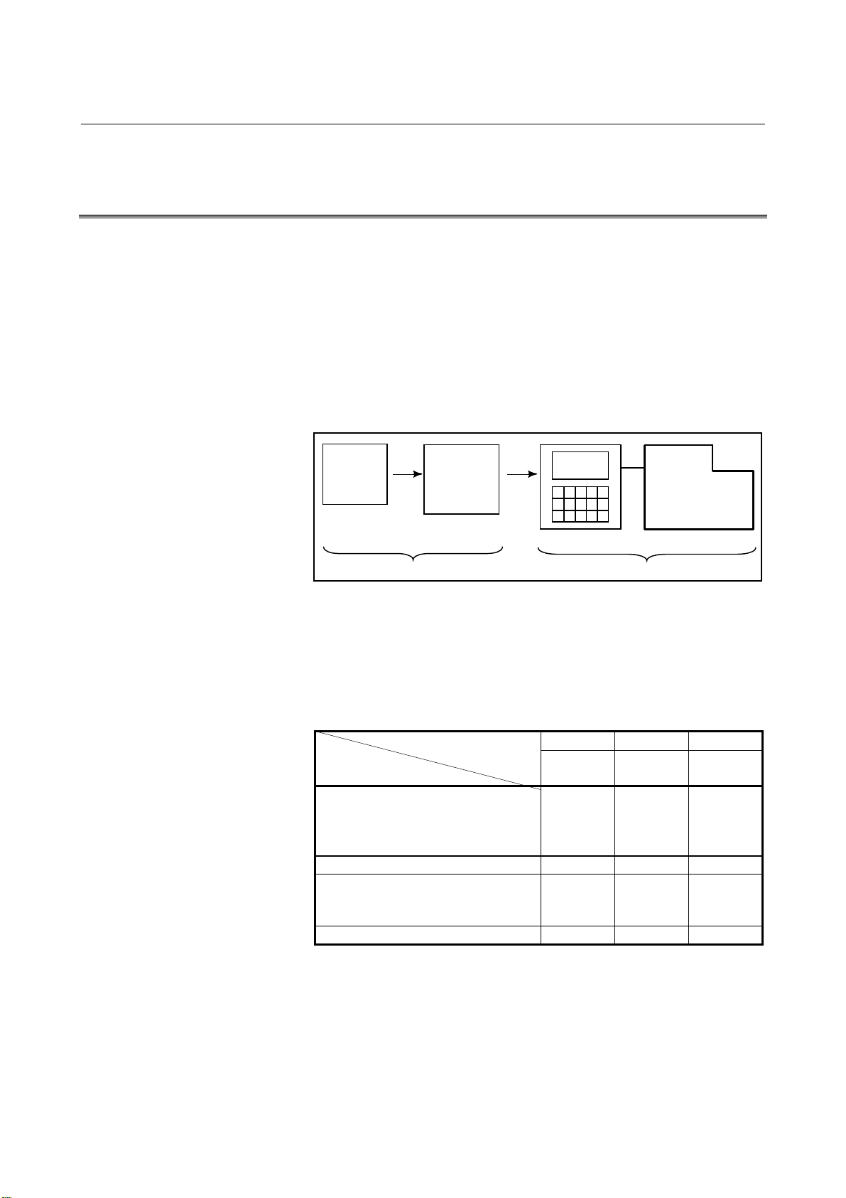
1.1 GENERAL FLOW OF OPERATION OF CNC MACHINE
TOOL
When machining the part using the CNC machine tool, first prepare the
program, then operate the CNC machine by using the program.
(1) First, prepare the program from a part drawing to operate the CNC
machine tool. How to prepare the program is described in the
OPERATOR’S MANUAL (PROGRAMMING).
(2) The program is to be read into the CNC system. Then, mount the
workpieces and tools on the machine, and operate the tools
according to the programming. Finally, execute the machining
actually. How to operate the CNC system is described in the
OPERATOR’S MANUAL (OPERATION).
Part
drawing
PROGRAMMING
Part
programming
CNC MACHINE TOOL
OPERATION
Before the actual programming, make the machining plan for how to
machine the part.
Machining plan-
1. Determination of workpieces machining range
2. Method of mounting workpieces on the machine tool
3. Machining sequence in every machining process
4. Machining tools and machining
Decide the machining method in every machining process.
Machining process
Machining procedure
1. Machining method :
Rough
Semi
Finish
2. Machining tools
3. Machining conditions :
Feedrate
Cutting depth
4. Tool path
123
Feed
cutting
Side
cutting
Hole
machining
- 5 -
Page 28
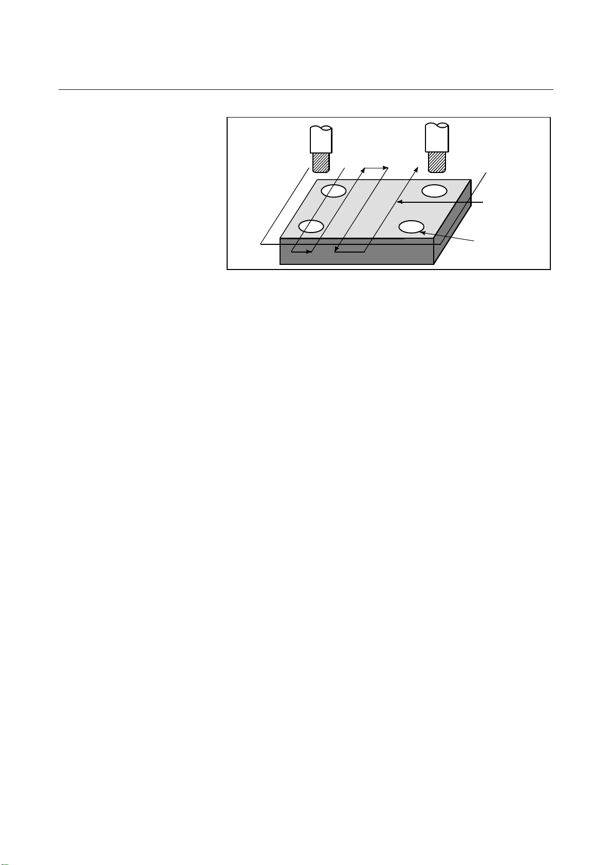
1.GENERAL GENERAL B-63784EN-1/01
Tool
Side cutting
Face cutting
Hole machining
Prepare the program of the tool path and machining condition
according to the workpiece figure, for each machining.
- 6 -
Page 29

B-63784EN-1/01 GENERAL 1.GENERAL
1.2 NOTES ON READING THIS MANUAL
NOTE
1 The function of an CNC machine tool system
depends not only on the CNC, but on the
combination of the machine tool, its magnetic
cabinet, the servo system, the CNC, the operator's
panels, etc. It is too difficult to describe the function,
programming, and operation relating to all
combinations.
This manual generally describes these from the
stand-point of the CNC. So, for details on a particular
CNC machine tool, refer to the manual issued by the
machine tool builder, which should take precedence
over this manual.
2 Headings are placed in the left margin so that the
reader can easily access necessary information.
When locating the necessary information, the reader
can save time by searching though these headings.
3 Machining programs, parameters, variables, etc. are
stored in the CNC unit internal non-volatile memory.
In general, these contents are not lost by the
switching ON/OFF of the power. However, it is
possible that a state can occur where precious data
stored in the non-volatile memory has to be deleted,
because of deletions from a maloperation, or by a
failure restoration.
In order to restore rapidly when this kind of mishap
occurs, it is recommended that you create a copy of
the various kinds of data beforehand.
4 This manual describes as many reasonable
variations in equipment usage as possible. It cannot
address every combination of features, options and
commands that should not be attempted.
If a particular combination of operations is not
described, it should not be attempted.
- 7 -
Page 30

Page 31

II OPERATION
Page 32

Page 33

B-63784EN-1/01 OPERATION 1.GENERAL
1 GENERAL
- 11 -
Page 34

1.GENERAL OPERATION B-63784EN-1/01
1.1 MANUAL OPERATION
Explanations
- Manual reference position return
The CNC machine tool has a position used to determine the machine
position.
This position is called the reference position, where the tool is replaced
or the coordinate are set. Ordinarily, after the power is turned on, the
tool is moved to the reference position.
Manual reference position return is to move the tool to the reference
position using switches and pushbuttons located on the operator's
panel.(See II-3.1)
Reference Position
Tool
Machine operator’s panel
Fig.1.1 (a) Manual reference position return
The tool can be moved to the reference position also with program
commands.
This operation is called automatic reference position return (See
Programming Manual II-6).
- 12 -
Page 35

B-63784EN-1/01 OPERATION 1.GENERAL
- The tool movement by manual operation
Using machine operator's panel switches, pushbuttons, or the manual
handle, the tool can be moved along each axis.
Machine operator's panel
Manual
pulse
generator
Tool
Workpiece
Fig.1.1 (b) The tool movement by manual operation
The tool can be moved in the following ways:
(i) Jog feed (See Section II-3.2)
The tool moves continuously while a pushbutton remains pressed.
(ii) Incremental feed (See Section II-3.3)
The tool moves by the predetermined distance each time a button
is pressed.
(iii) Manual handle feed (See Section II-3.4)
By rotating the manual handle, the tool moves by the distance
corresponding
to the degree of handle rotation.
(iv) Manual feed at an arbitrary angle (See Section II-3.5)
The tool moves in an arbitrary direction on a plane.
(v) Manual numeric command (See Section II-3.6)
By entering numeric data from the MDI keyboard, the tool moves
through the distance corresponding to the entered data.
- 13 -
Page 36

1.GENERAL OPERATION B-63784EN-1/01
1.2
TOOL MOVEMENT BY PROGRAMING – AUTOMATIC
OPERATION
Explanations
- Memory operation
Automatic operation is to operate the machine according to the created
program.
It includes memory, MDI and DNC operations. (See Section II-4).
Program
O1000 ;
M_ S_ T_ ;
G92 X_ ;
G00 ;
G01 ;
:
:
Fig. 1.2 (a) Tool Movement by Programming
Tool
After the program is once registered in memory of CNC, the machine
can be run according to the program instructions. This operation is
called memory operation.
CNC
Memory
Machine
Fig. 1.2 (b) Memory Operation
- 14 -
Page 37

B-63784EN-1/01 OPERATION 1.GENERAL
- MDI operation
After the program is entered, as an command group, from the MDI
keyboard, the machine can be run according to the program. This
operation is called MDI operation.
- DNC operation
CNC MDI keyboard
Program entry by
manual
Fig.1.2 (c) MDI operation
Machine
In this mode of operation, the program is not registered in the CNC
memory. It is read from the external input/output devices instead. This
is called DNC operation. This mode is useful when the program is too
large to fit the CNC memory.
- 15 -
Page 38

1.GENERAL OERATION B-63784EN-1/01
A
A
1.3 AUTOMATIC OPERATION
Explanations
- Program selection
Select the program used for the workpiece. Ordinarily, one program is
prepared for one workpiece. If two or more programs are in memory,
select the program to be used, by searching the program number
(Section II-4.4.1).
In memory or on a tape
O1001
G92
M30
O1002
G92
Program number
Work-1
program
Program number
Work-2
program
Program number
search
utomatic
operation
- Start and stop
M30
O1003
G92
M30
Fig.1.3 (a) Program Selection for Automatic Operation
Program number
Work-3 program
Pressing the cycle start pushbutton causes automatic operation to start.
By pressing the feed hold or reset pushbutton, automatic operation
pauses or stops. By specifying the program stop or program termination
command in the program, the running will stop during automatic
operation. When one process machining is completed, automatic
operation stops. (See Section II-4)
Cycle start
Feed hold Reset
Stop
Start
utomatic operation
Program stop
Program end
Fig.1.3 (b) Start and Stop for Automatic Operation
Stop caused
by program
- 16 -
Page 39

B-63784EN-1/01 OERATION 1.GENERAL
X
p
- Restart
You can continue machining of paused workpieces. If, for example, the
tool breaks during machining, you can replace the tool, and then restart
machining. (Refer to II-4.7.)
- Handle interruption
Tool
Workpiec e Workpiec e
When machining of a paused workpiece is rest arted. When a t ool breaks
Fig.1.3 (c) Restart on automatic operation
Paused
drilling
Tool
Tool breakage
While automatic operation is being executed, tool movement can
overlap automatic operation by rotating the manual handle. (See
Section II-4.13)
Tool position during
automatic operation
tion
Programmed
depth of cut
Z
Tool position after
handle interru
Depth of
cut by
Fig.1.3 (d) Handle Interruption for Automatic Operation
- 17 -
Page 40

1.GENERAL OERATION B-63784EN-1/01
1.4 TESTING A PROGRAM
Before machining is started, the automatic running check can be
executed. It checks whether the created program can operate the
machine as desired. This check can be accomplished by running the
machine actually or viewing the position display change (without
running the machine) (See Section II-5).
- 18 -
Page 41

B-63784EN-1/01 OERATION 1.GENERAL
1.4.1 Check by Running the Machine
Explanations
- Dry run
Remove the workpiece, check only movement of the tool. Select the
tool movement rate using the dial on the operator's panel. (See Section
II-5.2)
Tool
- Feedrate override
Table
Fig.1.4 (a) Dry run
Check the program by changing the feedrate specified in the program.
(See Programming II-5.2)
Feed rate specified by program : 100 mm/min.
Tool
Feed rate after feed rate override (20%) :
20 mm/min.
Workpiece
- 19 -
Fig 1.4 (b) Feedrate Override
Page 42

1.GENERAL OERATION B-63784EN-1/01
- Single block
Each time the cycle start button is pressed, one block of a program is
executed, then the tool stops.
A program is checked by executing it on a block-by-block basis. (See
Section II-5.3.)
Cycle start
Cycle start Cycle start
Tool
Cycle start
Workpiece
StopStop
Stop
Fig.1.4 (c) Single Block
- 20 -
Page 43

B-63784EN-1/01 OERATION 1.GENERAL
X
1.4.2
How to View the Position Display Change without Running the Machine
Explanations
- Machine lock
- Auxiliary function lock
The machine tool does not move, and only the position coordinates are
updated.
MDI
Tool
Workpiece
The tool remains stopped, and only the
positional displays of the axes change.
Fig 1.4 (d) Machine Lock
Y
Z
When automatic running is placed into the auxiliary function lock
mode during the machine lock mode (See Sections II-5.1), all auxiliary
functions (spindle rotation, tool replacement, coolant on/off, etc.) are
disabled. (See Section II-5.1)
- 21 -
Page 44

1.GENERAL OERATION B-63784EN-1/01
1.5 EDITING A PART PROGRAM
After a created program is once registered in memory, it can be
corrected or modified from the MDI panel (See Section II-8).
This operation can be executed using the part program storage/edit
function.
Program registration
CNC
Program correction or modification
Tape reader
CNC tape
(program)
Fig.1.5 (a) Part Program Editing
MDI
CNC
- 22 -
Page 45

B-63784EN-1/01 OERATION 1.GENERAL
1.6 DISPLAYING AND SETTING DATA
The operator can display or change a value stored in CNC internal
memory by key operation on the MDI screen (See II-9).
Data setting
Data display
Screen Keys
MDI
CNC memory
Fig.1.6 (a) Displaying and Setting Data
Explanations
- Offset value
Screen
MDI
Fig.1.6 (b) Displaying and Setting Offset Values
Setting
Display
Geometry
compensation
Tool compensation
number1 12.3 25.0
Tool compensation 20.0 40.0
number2
Tool compensation . . . . . .
number3
. . . . . . . . . . . . . . .
. . . . . . . . . . . . . . .
CNC memory
Wear
compensation
The tool has the tool dimension (length, diameter). When a workpiece
is machined, the tool movement value depends on the tool dimensions.
By setting tool dimension data in CNC memory beforehand,
automatically generates tool routes that permit any tool to cut the
workpiece specified by the program. Tool dimension data is called the
offset value (See Section II-9.1).
- 23 -
Page 46

1.GENERAL OERATION B-63784EN-1/01
g
A
1st tool path
Ma ch in ed
shape
2nd tool path
Offset value of the 1s t tool
Offset value of the 2nd tool
Fig.1.6 (c) Offset Value
- Displaying and setting
operator's setting data
Apart from parameters, there is data that is set by the operator in
operation. This data causes machine characteristics to change.
For example, the following data can be set:
- Inch/Metric switching
- Selection of I/O devices
- Mirror image cutting on/off
The above data is called setting data (See Section II-9.3).
Setting data
·
Inch/Metric switching
·
Selection of I/O device
·
Mirror image ON/OFF setting
:
:
:
CNC Memory
Operational
characteristics
utomatic
operation
Movement of
the machine
Screen Keys
MDI panel
Settin
Displaying
Program
Fig.1.6 (d) Displaying and Setting Operator's setting data
- 24 -
Page 47

B-63784EN-1/01 OERATION 1.GENERAL
A
- Displaying and setting
parameters
The CNC functions have versatility in order to take action in
characteristics of various machines.
For example, CNC can specify the following:
- Rapid traverse rate of each axis
- Whether increment system is based on metric system or inch
system.
- How to set command multiply/detect multiply (CMR/DMR)
Data to make the above specification is called parameters (See Section
II-9.3).
Parameters differ depending on machine tool.
Parameter
Rapid traverse rate
Position control
Reference position return
Backlash compensation data
Pitch error compensation
data
:
:
:
Screen Keys
MDI
Setting
Display
CNC memory
Operational
characteristics
Program
Fig.1.6 (e) Displaying and setting parameters
utomatic
operation
Movement
of the
machine
- 25 -
Page 48

1.GENERAL OERATION B-63784EN-1/01
- Data protection key
A key called the data protection key can be defined. It is used to
prevent part programs, offset values, parameters, and setting data from
being registered, modified, or deleted erroneously. Refer to the relevant
manual published by the machine tool builder for details.
Data Setting
Screen
MDI
Keys
Protection Key
Registration / modification inhibition
Program
Offset value
Parameters
Setting data
CNC memory
Fig.1.6 (f) Data Protection Key
Signal
Machine operator's
panel
Data protection
key
- 26 -
Page 49

B-63784EN-1/01 OERATION 1.GENERAL
1.7 DISPLAY
1.7.1 Program Display
The contents of the currently active program are displayed. In addition,
the programs scheduled next and the program list are displayed.(See
Section II-10.1)
Active sequence number
Active program number
Program
CONTEN
The cursor indicates the currently
executed location
Fig.1.7 (a) Currently executed program
- 27 -
Page 50

1.GENERAL OERATION B-63784EN-1/01
Fig.1.7 (b) Program list
- 28 -
Page 51

B-63784EN-1/01 OERATION 1.GENERAL
X
X
1.7.2 Current Position Display
The current position of the tool is displayed with the coordinate values.
The distance from the current position to the target position can also be
displayed. (See Section II-10.5)
Y
Y
Workpiece coordinate system
- 29 -
Page 52

1.GENERAL OERATION B-63784EN-1/01
1.7.3 Operator Message Display
Messages stored to memory are displayed when the operator must be
instructed during machining. (Refer to II-10.6)
1.7.4 Alarm Display
"Load t he workpi ece."
CRT di spl ay
Me m o r y
Message 1
Message displ ay
number
Message 2
Message 3
When a trouble occurs during operation, error code and alarm message
are displayed on the screen. (See Section II-10.7)
See PROGRAMMING Appendix F for the list of error codes and their
meanings.
- 30 -
Page 53

B-63784EN-1/01 OERATION 1.GENERAL
1.7.5 Parts Count Display, Run Time Display
When this option is selected, five types of run time and number of parts
are displayed on the screen. (See Section II-10.10)
- 31 -
Page 54

1.GENERAL OERATION B-63784EN-1/01
X
X
1.7.6 Graphic Display
Programmed tool movement can be displayed on the following planes:
(See Section II-10.8)
1) XY plane
2) YZ plane
3) XZ plane
4) Three dimensional display
(1)
Y
Display on the XY plane
Z
Display on the XZ plane
Fig. 1.7 (c) Graphic display
(2)
Z
Display on the YZ plane
(4)(3)
X
Three dimensional display (isometric)
Z
Y
Y
- 32 -
Page 55

B-63784EN-1/01 OERATION 1.GENERAL
A
1.8 DATA INPUT/OUTPUT
Programs, offset values, parameters, etc. input in CNC memory can be
output to paper tape, cassette, or a floppy disk for saving. After once
output to a medium, the data can be input into CNC memory. (See II-
12.)
FANUC Floppy
FANUC Floppy
cassette
Cassette
Memory
Program
Offset
Parameters
:
:
:
CNC
Reader/puncher
interface
Fig.1.8 (a) Data Output
SYSTEM P
utomatic programming
system
Memory card adapter
(incorporated CNC)
Floppy disk
Memory card
- 33 -
Page 56

2.OPERATIONAL DEVICES OPERATION B-63784EN-1/01
2 OPERATIONAL DEVICES
The available operational devices include the setting and display unit
attached to the CNC, the machine operator's panel, and external
input/output devices such as a PPR, Handy File, Floppy Cassette, and
FA Card.
- 34 -
Page 57

B-63784EN-1/01 OPERATION 2.OPERATIONAL DEVICES
2.1 SETTING AND DISPLAY UNITS
The setting and display units are shown in Subsections II-2.1.1 to II-
2.1.3.
9.5"/10.4" LCD unit ................................................................II-2.1.1
MDI unit..................................................................................II-2.1.2
MDI unit (full-keyboard) ........................................................II-2.1.3
- 35 -
Page 58

2.OPERATIONAL DEVICES OPERATION B-63784EN-1/01
2.1.1 9.5"/10.4" LCD Unit
LCD units are following three kinds.
- 9.5-inch monochrome (with graphic display)
- 9.5-inch monochrome (without graphic display)
- 10.4-inch monochrome (with graphic display)
NOTE
The LCD brightness of the 9.5-inch monochrome
LCD unit with or without graphic display is lowered at
low ambient temperatures. (Particularly, the LCD
screen is dark immediately after power-up.) This is a
characteristic of the LCD, and not a failure. As the
ambient temperature rises, the LCD screen becomes
brighter.
- 36 -
Page 59

B-63784EN-1/01 OPERATION 2.OPERATIONAL DEVICES
/
A
AK@
2.1.2 MDI Unit
Help key
Shift key
ResetT key
O(N)GEP
RESET
XUYVZWQ
I,J
HELP
M#S=T*L
F[D]H&B
SHIFT
PAG E
PAG E
Page change keys
ddress/numeric keys
8 9
7
C
?
R
SP
5 64
21
-
0
EOB
POS PROG
SYSTEM MESSAGE GRAPH
Function key
Cursor keys
3
.
CAN
OFFSET
SETTING
ALTER
INSERT
DELETE
INPUT
CUSTOM
Edit key
Cancel (CAN) key
Input key
- 37 -
Page 60

2.OPERATIONAL DEVICES OPERATION B-63784EN-1/01
A
A
/
K
¥
,
2.1.3 MDI Unit (Full-keyboard)
Rest kry
C
ddress/numeric
keys
Shift key
Help key
RESET
I J
R S
7
-
+
!B"
,
8 9
5 64
21
0
=
:L;
T U
3
.
D#E$F%G
MSPN O?P
V[W]X(Y
-
ALTER
SHIFT
CALC
INSERT
HELP
CAN
DELETE
EOB
INPUT
POS PROG
SYSTEM MESSAGE GRAPH
PAG E
PAG E
OFFSET
SETTING
H
&
*
Q
<
>
Z
)
@
CUSTOM
Function keys
Page change keys
Cursor kys
Edit keys
Input keyCancel (CAN) key
- 38 -
Page 61

B-63784EN-1/01 OPERATION 2.OPERATIONAL DEVICES
2.1.4 MDI Unit (Main Panel A/B) for Machine Operator's Panel
The following MDI unit for machine operator's panel can be used.
Reset key
Address/numeric keys
Shift key
Function keys
Page change key
Help key
Edit keys
- 39 -
Input key
Cancel key
Cursor keys
Page 62

2.OPERATIONAL DEVICES OPERATION B-63784EN-1/01
RESET
2.2 EXPLANATION OF THE KEYBOARD
Table2.2 (a) Explanation of the MDI keyboard
Number Name Explanation
1 RESET key Press this key to reset the CNC, to cancel an alarm, etc.
2 HELP key Press this button to use the help function when uncertain about the operation of an MDI
key (help function).
3
Soft keys
4 Address and numeric
keys
N
,
)
4
The soft keys have various functions, according to the Applications.
The soft key functions are displayed at the bottom of the screen.
Press the inside of the rectangle area of the soft key button on the screen, when the
CNC with the touch panel function is used.
The button of the soft key becomes dented and indicated.
And, the same operation treatment as the present soft key is done.
Press these keys to input alphabetic, numeric, and other characters.
5 SHIFT key Some keys have two characters on their keytop. Pressing the <SHIFT> key switches
the characters. Special character # is displayed on the screen when a character
SHIFT
indicated at the bottom right corner on the keytop can be entered.
6 INPUT key When an address or a numerical key is pressed, the data is input to the buffer, and it is
displayed on the screen. To copy the data in the key input buffer to the offset register,
INPUT
etc., press the key. This key is equivalent to the [INPUT] key of the soft keys, and
either can be pressed to produce the same result.
7 Cancel key
CAN
Press this key to delete the last character or symbol input to the key input buffer.
When the key input buffer displays
>N001X100Z_
and the cancel <CAN> key is pressed, Z is canceled and
>N001X100_
is displayed.
8 Program edit keys Press these keys when editing the program.
ALTER
: Alteration
ALTER INSERT
9 Function keys
DELETE
INSERT
: Insertion
DELETE
: Deletion
Press theses keys to switch display screens for each function.
See lll - 2.5 for details of the function keys.
POS PROG
- - -
- 40 -
Page 63

B-63784EN-1/01 OPERATION 2.OPERATIONAL DEVICES
Table2.2 (a) Explanation of the MDI keyboard
Number Name Explanation
10 Cursor move keys There are four different cursor move keys.
: This key is used to move the cursor to the right or in the forward
direction. The cursor is moved in short units in the forward direction.
: This key is used to move the cursor to the left or in the reverse direction.
The cursor is moved in short units in the reverse direction.
: This key is used to move the cursor in a downward or forward direction.
The cursor is moved in large units in the forward direction.
: This key is used to move the cursor in an upward or reverse direction.
The cursor is moved in large units in the reverse direction.
11 Page change keys Two kinds of page change keys are described below.
PAGE
PAGE
PAGE
PAGE
: This key is used to changeover the page on the screen in the
forward direction.
: This key is used to changeover the page on the screen in the
reverse direction.
- 41 -
Page 64

2.OPERATIONAL DEVICES OPERATION B-63784EN-1/01
2.3 OPERATION SCREEN DISPLAY
The operation screens used in the CNC are classified into the following
levels and managed hierarchically:
- Function
- Chapter
Function
Chapter
Function 1
Operation screen
1 of function 1
Operation screen
2 of function 1
Operation screen
1 of function 2
Function 2
Operation screen
2 of function 2
To display a desired operation screen, select a function then chapter.
A function can be selected by using one of the two methods explained
below. A desired function can be selected using either method.
- Using a function key on the MDI panel to select a function
When a function is selected using this method, the soft key
display automatically changes to the chapter selection menu.
- Selecting a function displayed on a soft key
When a function is selected using this method, the soft key
display does not automatically change to the chapter
selection menu. To change the soft key display to the
chapter selection menu, select the chapter key.
To select a chapter, use one of the following methods:
- Pressing a function key on the MDI panel several times
repeatedly
Repeatedly pressing a function key displays the chapters of
the corresponding function sequentially. After the last
chapter is selected, the first chapter is selected again. This
method is useful when you want to display all the chapters of
a function.
- Selecting from the chapters displayed on the soft keys
Select from the chapter selection menu displayed on the soft
keys. This method is useful when you determine the chapter
of a target operation screen.
- 42 -
Page 65

B-63784EN-1/01 OPERATION 2.OPERATIONAL DEVICES
2.4
OPERATIONS SUPPORTED BY EACH OPERATION SCREEN
The operation screens support a wide range of operations.
On the program screen, for example, you can select and search for a
desired program. On the setting screens, operations such as altering the
settings and outputting the setting data to external input/output devices
are possible. The operations that can be performed vary depending on
the operation screens.
A desired operation can be selected and executed using an operation
menu key (soft key) from an operation screen.
Function
Chapter
Operation
Operation screen
1 of function 1
Operation 1
Operation 2
Function 1
Operation screen
2 of function 1
Operation 1
Operation 2
Operation screen
1 of function 2
Operation 1
Operation 2
Function 2
Operation screen
2 of function 2
Operation 1
Operation 2
- 43 -
Page 66

2.OPERATIONAL DEVICES OPERATION B-63784EN-1/01
2.5 FUNCTION KEYS AND SOFT KEYS
2.5.1 General Screen Operations
1 Press a function key on the MDI panel. The chapter selection soft
keys that belong to the selected function appear.
POS
SYSTEM
PROG
MESSAGE
OFFSET
SETTING
GRAPH
CUSTOM
2 Press one of the chapter selection soft keys. The screen for the
selected chapter appears.
3 To perform operations on the displayed screen of the chapter,
press the operation menu key.
For example, pressing the key displays the chapter
PROG
selection soft keys shown below. When these soft keys are displayed
for the first time, the first chapter is selected. (In this example, "TEXT"
is selected.) To display the operation selection menu for this screen,
press the operation menu key located at the right end.
operation menu key
4 To redisplay the chapter menu keys for chapter selection while the
operation selection menu is being displayed, press the chapter
key.
chapter key
The general screen display procedure is explained above. However,
the actual display procedure varies from one screen to another. For
details, see the description of the individual operations.
- 44 -
Page 67

B-63784EN-1/01 OPERATION 2.OPERATIONAL DEVICES
2.5.2 Function Keys
Function keys are provided to select the type of screen to be displayed.
The following function keys are provided on the MDI panel:
POS
PROG
OFFSET
SETTING
SYSTEM
MESSAGE
GRAPH
Press this key to display the position screen.
Press this key to display the program screen.
Press this key to display the offset/setting screen.
Press this key to display the system screen.
Press this key to display the message screen.
Press this key to display the graphics screen.
- 45 -
Page 68

2.OPERATIONAL DEVICES OPERATION B-63784EN-1/01
2.5.3 Soft Keys
Instead of the function keys, soft keys can also be used to select the type
of screen to be displayed. In addition, soft keys are used for actual
operations. The subsequent sections show a function menu and chapter
selection menus.
NOTE
The soft keys explained below are not always
displayed. Some of the soft keys do not appear
depending on the set options.
2.5.4 Function Selection Keys
To select a function with the soft key, press the function
selection menu key to change the soft keys to the function selection keys,
then press the desired function selection key.
Functions can be selected in any mode.
Detailed function selection is performed with the chapter selection
keys.
The following function selection keys are provided:
Function menu key
Function key
NO.
(MDI panel)
(1) POSITION
(2) PROGRAM
(3) OFFSET/SETTING
(4) SYSTEM
(5) MESSAGE
(6) GRAPHIC
POS
PROG
OFFSET
SETTING
SYSTEM
MESSAGE
GRAPH
Function selection key
(soft key)
Explanation
Current-position information screens indicating
absolute coordinates, machine coordinates,
relative coordinates, remaining amounts of travel,
and so forth can be selected.
The part program display screen, program check
screen, and so forth can be selected.
The tool offset screen, workpiece origin offset
screen, and so forth can be selected.
The parameter screen, diagnosis screen, PMC
screen, and so forth can be selected.
Alarm message and operator message screens
can be selected.
Graphics screens can be selected.
- 46 -
Page 69

B-63784EN-1/01 OPERATION 2.OPERATIONAL DEVICES
2.5.5 Chapter selection keys
The function selection keys are used to select large items (functions).
Each of them is further divided into smaller items (chapters). These
items (chapters) are selected using chapter selection keys. To select a
chapter, press the chapter key to display chapter selection keys on the
soft keys first, then press the target chapter selection key. Change from
one chapter to another can also be performed by pressing a function
hard key several times repeatedly. The following sections list the
chapters contained in each function.
2.5.5.1 Position
Function key on the MDI panel Soft keys
POS
POSITION CHAPTER
(1) (2) (3) (4) (5) (6) (7) (8) (9) (10)
NO. Chapter menu Explanation
(1) OVERALL Selects the overall position display screen.
(2) RELATIVE Selects the relative position display screen.
(3) ABSOLUTE Selects the position display screen based on the
workpiece coordinate system.
(4) MACHINE Selects the position display screen based on the
machine coordinate system.
(5) MANUAL OVRLAP Selects the operation screen for performing
manual handle feed interrupt operation.
(6) BLOCK RESTRT Selects the operation screen for restarting
operation from a block in which the previous
operation was interrupted.
(7) PRGRAM RESTRT Selects the operation screen for restarting the
interrupted program operation.
(8) TOOL HEAD Displays the absolute coordinates and actual
feedrate of the tool tip during handle feed in the
longitudinal direction of the tool, handle feed in
the transverse direction of the tool, and rotational
handle feed around the tool tip.
(9) HANDLE PULSE Displays the handle pulse interrupt amount for
performing three-dimensional handle feed.
- 47 -
Page 70

2.OPERATIONAL DEVICES OPERATION B-63784EN-1/01
2.5.5.2 Program
Function key on the MDI panel Soft keys
PROG PROGRAM
CHAPTER
(1) (2) (3) (4) (5) (6) (7) (8) (9) (10)
(11) (12) (13) (14) (15) (16) (17) (18) (19)
No. Chapter menu Explanation
(1) TEXT Selects the screen for displaying the contents of a
currently selected part program.
(2) DIR. MEMORY Selects the screen for displaying a list of currently
registered part programs.
(3) HDD DIR. Selects the screen for displaying a list of files saved on
the hard disk of the data server.
(4) HOST DIR. Selects the screen for displaying a list of files on the host
computer.
(5) CHANGE
HOST
(6) CHECK Selects the screen for displaying a program, positions,
(7) LAST Selects the screen for displaying the values specified in
(8) ACTIVE Selects the screen for displaying the values specified in
(13) POS.DATA Selects the screen for displaying information about
Selects the screen for changing to connect the host
computer.
modal information, and so forth at the same time.
the block immediately preceding the block currently
being executed, and modal values such as G code and F
code which were specified in the blocks up to the
preceding block.
the block currently being executed, and modal values
such as G code and F code which were specified in the
blocks up to the current block.
position compensation.
- 48 -
Page 71

B-63784EN-1/01 OPERATION 2.OPERATIONAL DEVICES
2.5.5.3 Offset/Setting
Function key on the MDI panel
OFFSET
SETIN G
OFFSET
Soft keys
CHAPTER
(1) (2) (3) (4) (5) (6) (7) (8) (9) (10)
(11) (12) (13) (14) (15) (16) (17) (18) (19)
(21) (22) (23) (24) (25) (26) (27) (28) (29)
No. Chapter menu Explanation
(1) TOOL Selects the screen for setting tool offset values.
WORK
(2)
OFFSET
(3) MEASURE_TL Selects the screen for tool length measurement.
SETTING
(4)
PARAMETER
(5) TIMER
(6) RS232C
(7) MEMCARD Selects the screen for memory card operation
(8) MACRO VAR. Selects the screen for setting macro variables.
(9) TOOL LIFE
T CODE
(11)
OFFSET
(12) FOFS Selects the fixture offset screen.
(13) DOFS Selects the dynamic tool offset screen.
(14) SU&NUTATR Selects the SU&NUTATR offset screen.
(15) COM. SETING
OPERAT
(16)
PANEL
MENU
(17)
SWITCH
(29) DISP COLOR
Selects the screen for setting workpiece origin offset
values.
Selects the screen for specifying setting parameters.
Selects the screen for displaying information about the
number of machined parts and operation time.
Selects the screen for operating devices connected to
the RS-232C interface
Selects the screen for making settings related to tool life
management.
Selects the screen for setting a tool number, pot number,
and value for tool offset by tool number.
Selects the screen for making RS-232C and RS-422
settings.
Selects the screen for using part of the operation
switches on the machine operator's panel as soft
switches.
Selects the screen for setting part of the switch signals
input from the machine for CNC operation.
Selects the screen for adjusting tbrightness of the
monochrome LCD.
- 49 -
Page 72

2.OPERATIONAL DEVICES OPERATION B-63784EN-1/01
2.5.5.4 System
Function key on the MDI panel
SYSTEM
SYSTEM
Soft keys
CHAPTER
(1) (2) (3) (4) (5) (6) (7) (8) (9) (10)
(11) (12) (13) (14) (15) (16) (17) (18) (19)
(21) (22) (23) (24) (25) (26) (27) (28) (29)
No. Chapter menu Explanation
(1) PARAMETER Selects the screen for parameter setting.
(2) PITCH ERROR Selects the screen for pitch error compensation setting.
(3) DIAGNOSIS Selects the screen for displaying the CNC status information.
(4) DI/DO MONITOR Selects the screen for displaying the signal status.
(5) PERIOD
MAINTE
(6) MAINTE INFO Selects the screen for setting maintenance information.
(7) SYSTEM
CONFIG
(8) PMC Selects the screen related to the PMC.
(11) WAVE DIAGNS Selects the screen for graphically displaying data such as a
(12) SERVO Selects the screen for making servo settings.
(13) SPINDLE Selects the screen for making spindle settings.
(14) HPCC Selects the screen for setting high-precision contour control.
(17) FSSB Selects the screen for setting the high-speed serial servo bus
(18) VOLUMETRIC Selects the screen for setting three-dimensional error
(19) DISPLY
MEMORY
(23) ETHERNET Selects the screen for setting related to ethernet board.
(24) DATA SERVER Selects the screen for Data server maintenance and setting.
(25) ALARM
HISTORY
(26) OPERAT
HISTORY
(27) SYSTEM LOG Selects the screen for displaying the descriptions of system
(28) TOUCH PANEL Selects the screen for setting the touch panel.
Select the screen for setting those items that require routine
maintenance.
Selects the screen for displaying the current system status.
servo positional deviation, torque, and machine signals.
(FSSB: FANUC Serial Servo Bus).
compensation values.
Selects the screen for displaying the current CNC memory
contents
Selects the screen for displaying the descriptions of alarms
issued before
Selects the screen for displaying a history of keystrokes.
alarms issued before.
- 50 -
Page 73

B-63784EN-1/01 OPERATION 2.OPERATIONAL DEVICES
2.5.5.5 Messages
2.5.5.6 Drawing
Function key on the MDI panel
MESSAGE
MESSAGE
Soft keys
CHAPTER
(1) (2) (3) (4) (5) (6) (7) (8) (9) (10)
No. Chapter menu Explanation
(1) ALARM Selects the alarm message screen.
(2) OPERATOR Selects the operator message screen.
(3) ETHERNET Selects the screen for displaying the log related to
Ethernet board.
Function key on the MDI panel
GRAPH
GRAPHIC
Soft keys
CHAPTER
(1) (2) (3) (4) (5) (6) (7) (8) (9) (10)
No. Chapter menu Explanation
(1) Tool Path Selects the screen for graphic display of the tool path.
(2) GRAPH
PARAM
Selects the screen for setting graphic display of the tool
path.
- 51 -
Page 74

2.OPERATIONAL DEVICES OPERATION B-63784EN-1/01
2.5.6 Key Input and Input Buffer
2.5.6.1 Inserting characters
When an address and a numerical key are pressed, the character
corresponding to that key is input once into the key input buffer. The
contents of the key input buffer is displayed at the bottom of the screen.
A "_" is displayed at the end of the key input data indicating the input
position of the next character.
Fig.2.5.6 (a) Key Input Buffer Display
To input the lower character of the keys that have two
characters inscribed on them, first press the <SHIFT> key and then the
key in question.
When the <SHIFT> key is pressed, "_" indicating the next character
input position changes to "~". Now lowercase characters can be
entered (shift state).
When a character is input in shift status the shift status is
canceled. Furthermore, if the <SHIFT> key is pressed in shift status,
the shift status is canceled.
Example
Inserting G90 after N001 when "N001X100.0Y200.0F100.0;_" is
displayed as the contents of the key input buffer:
- Press cursor key ↑ to move the cursor to the following position:
N001_X100.0Y200.0F100.0;
- Key in G90.
N001G90_X100.0Y200.0F100.0;
- Press cursor key ↓ to move the cursor to the following position:
N001G90X100.0Y200.0F100.0;_
- 52 -
Page 75

B-63784EN-1/01 OPERATION 2.OPERATIONAL DEVICES
2.5.6.2 Deleting characters
Move the cursor to a position next to a character you want to
Example
delete, then press the key.
When the key is pressed while the shift button is held
CAN
CAN
down, the contents of the key input buffer are all deleted.
Deleting Y200.0 when "N001X100.0Y200.0F100.0;_" is displayed as
the contents of the key input buffer:
- Press cursor key <↑> to move the cursor to the following position:
N001X100.0Y200.0_F100.0;
- Press the <CAN> key six times.
N001X100.0_F100.0;
- Press the cursor key <↓> to move the cursor to the following
position:
N001X100.0F100.0;_
- 53 -
Page 76

2.OPERATIONAL DEVICES OPERATION B-63784EN-1/01
2.5.7 Warning Messages
After a character or number has been input from the MDI
panel, a data check is executed when key or a soft key is pressed.
In the case of incorrect input data or the wrong operation a flashing
warning message will be displayed on the status display line.
Warning message display
Display of key input buffer
Soft key display
Fig. 2.5.7 Warning message display
Table2.5.7 Warning Messages
Warning message Content
FORMAT ERROR The format is incorrect.
WRITE PROTECT Key input is invalid because of data protect key or
the parameter is not write enabled.
DATA IS OUT OF RANGE The input value exceeds the permitted range.
TOO MANY DIGITS The input value exceeds the permitted number of
digits.
WRONG MODE An appropriate mode is not selected.
EDIT REJECTED It is not possible to edit in the current CNC
status.
- 54 -
Page 77

B-63784EN-1/01 OPERATION 2.OPERATIONAL DEVICES
2.6 LANGUAGE SELECTION
The Japanese, English, German, French, Italian, Spanish, Swedish, and
Chinese are prepared as display languages. Select the language to be
displayed by parameters.
Fig. 2.6 (a) Example of operation screen : JAPANESE
Fig. 2.6 (b) Example of operation screen : ENGLISH
- 55 -
Page 78

2.OPERATIONAL DEVICES OPERATION B-63784EN-1/01
2.7 EXTERNAL I/O DEVICES
Three types of external input/output devices are available. This section
outlines each device. For details on these devices, refer to the
corresponding manuals listed below.
Table 2.7(a) External I/O device
Max.
Device name Usage
FANUC Handy
File
FANUC Floppy
Cassette
FANUC FA
Card
Easy-to-use, multi function input/output
device. It is designed for FA equipment
and uses floppy disks.
Input/output device. Uses floppy disks. 2500m B-66040E
Compact input/output device. Uses FA
cards.
Storage
capacity
3600m B-61834E
160m B-61274E
The following data can be input/output to or from external input/output
devices:
1. Programs
2. Offset data
3. Parameters
4. Custom macro common variables
For how data is input and output, see II-12.
Reference
manual
- 56 -
Page 79

B-63784EN-1/01 OPERATION 2.OPERATIONAL DEVICES
Parameter
Before an external input/output device can be used, parameters must be
set as follows.
CNC
MAIN CPU BOARD
Channel 1
JD5A
Reader
puncher
I/O CHANNEL=1 I/O CHANNEL=2
Channel 2
JD5B
Reader
puncher
DISPLAY UNIT
Channel 3
JD36A
RS-232-C
Host
computer
I/O CHANNEL=3 I/O CHANNEL=13
Channel 13
JD6A
RS-422RS-232-CRS-232-C
Host
computer
Each external input/output device is temporarily assigned a device
number from 1 to 6. When four external input/output devices are used,
for example, a device number from 1 to 4 is assigned to each device.
After the device numbers are assigned to the external input/output
devices, their specifications are set in parameter Nos. 5110 to 5162.
The numbers of the external input/output devices attached to channels
1, 2, 3, and 13 are set in parameter Nos. 5001, 5002, 5003, and 5013.
Foreground
Background
Channels used by
input/output
devices
Channel No.
0020
0021
0022
0023
Parameter number
- 57 -
1
5001
2
5002
3
5003
13
5013
Device number
used for each
channel
Device No.
5110
1
5111
5112
5120
2
5121
5122
3 :
4 :
5 :
5160
6
5161
5162
Device specification
Number of stop bits
Baud rate
Device specification
Number of stop bits
Baud rate
Device specification
Number of stop bits
Baud rate
Page 80

2.OPERATIONAL DEVICES OPERATION B-63784EN-1/01
UC
r
2.7.1 FANUC Handy File
The Handy File is an easy-to-use, multi function floppy disk
input/output device designed for FA equipment. By operating the Handy
File directly or remotely from a unit connected to the Handy File,
programs can be transferred and edited.
The Handy File uses 3.5-inch floppy disks.
One or more programs (up to 1.44M bytes, which is equivalent to the
memory capacity of 3600-m paper tape) can be stored on one floppy
disk.
RS-422
Interface
RS-232-C
Interface
FANUC
Handy File
2.7.2 FANUC Floppy Cassette
When the Floppy Cassette is connected to the CNC, machining
programs stored in the CNC can be saved on a Floppy Cassette, and
machining programs saved in the Floppy Cassette can be transferred to
the CNC.
RS-232-C o
RS-422 Interface
(Punch panel, etc.)
FAN
RS-232-C Interface
(Punch panel, etc.)
POWER
OFF
ON
- 58 -
Page 81

B-63784EN-1/01 OPERATION 2.OPERATIONAL DEVICES
2.7.3 FANUC FA Card
An FA Card is a memory card used as an input medium in the FA field.
It is compact, but has a large memory capacity with high reliability, and
requires no special maintenance.
When an FA Card is connected to the CNC via the card adapter,
machining programs stored in the CNC can be transferred to and saved
in an FA Card. Machining programs stored on an FA Card can also be
transferred to the CNC.
RS-232-C Interface
(Punch panel, etc.)
READY
READ
WRITE
ALARM
RESET
- 59 -
Page 82

2.OPERATIONAL DEVICES OPERATION B-63784EN-1/01
2.8 POWER ON/OFF
2.8.1 Turning on the Power
Procedure of turning on the power
Procedure
1 Check that the appearance of the CNC machine tool is normal.
(For example, check that front door and rear door are closed.)
2 Turn on the power according to the manual issued by the machine
tool builder.
3 After the power is turned on, check that the position screen is
displayed. An alarm screen is displayed if an alarm occurs upon
power-on. If the screen shown in Maintenance Manual (Sec. 7.11)
is displayed, a system failure may have occurred.
Screen & Position display
4 Check that the fan motor is rotating.
WARNING
Until the positional or alarm screen is displayed at the
power on, do not touch them. Some keys are used
for the maintenance or special operation purpose.
When they are pressed, unexpected operation may
be caused.
- 60 -
Page 83

B-63784EN-1/01 OPERATION 2.OPERATIONAL DEVICES
2.8.2 Power Disconnection
Power Disconnection
Procedure
1 Check that the LED indicating the cycle start is off on the
operator's panel.
2 Check that all movable parts of the CNC machine tool is stopping.
3 If an external input/output device such as the Handy File is
connected to the CNC, turn off the external input/output device.
4 Continue to press the POWER OFF pushbutton for about 5
seconds.
5 Refer to the machine tool builder's manual for turning off the
power to the machine.
CAUTION
In the cable connecting the input/output unit and
RS-232-C interface, the SG signal and each signal
must be paired as shown in the figure below.
- 61 -
Page 84

3.MANUAL OPERATION OPERATION B-63784EN-1/01
3 MANUAL OPERATION
MANUAL OPERATION are as follows :
3.1 Manual reference position return
3.2 Jog feed
3.3 Incremental feed
3.4 Manual handle feed
3.5 Manual feed in a specified direction
3.6 Manual numeric command
3.7 Manual absolute on and off
3.8 Effect of manual intervention
3.9 Three-dimensional handle feed
3.10 Changing tool length compensation in the longitudinal
direction of the tool
3.11 Tool holder offset
3.12 Rotary axis origin compensation and rotary axis offset
3.13 Precautions during 3-dimensional handle feed
3.14 Displaying the coordinates of the tool tip
3.15 Displaying pulse values and amount of movement by manual
interrupt
3.16 Manual interruption function for three-dimensional coordinate
conversion
- 62 -
Page 85

B-63784EN-1/01 OPERATION 3.MANUAL OPERATION
X
C
X
C
AXIS
3.1 MANUAL REFERENCE POSITION RETURN
The tool is returned to the reference position as follows :
The tool is moved in the direction specified in parameter ZMI (bit 5 of
No. 1006) for each axis with the reference position return switch on the
machine operator's panel. The tool moves to the deceleration point at
the rapid traverse rate, then moves to the reference position at the FL
speed. The rapid traverse rate and FL speed are specified in parameters
(No. 1420,1421, and 1425).
Rapid traverse override is effective during rapid traverse.
When the tool has returned to the reference position, the reference
position return completion LED goes on.
Procedure
EDIT
F0
Deceleration
Rapid traverse motion
Rapid traverse rate
(rapid traverse override is
effective)
Procedure for Manual Reference Position Return
MODE
REMOTE
MEMORY
ZERO
RETURN
RAPID TRAVERSE
OVERRIDE (%)
50 10025
DIRECTION
+C +Z +Y
RAPID
MDI
TEACHJOGHANDLE
+X-X
1 Press the reference position return switch, one of the mode
selection switches.
2 To decrease the feedrate, press a rapid traverse override switch.
When the tool has returned to the reference position, the reference
position return completion LED goes on.
3 Press the feed axis and direction selection switch corresponding to
the axis and direction for reference position return. Continue pressing
the switch until the tool returns to the reference position. The tool
moves to the deceleration point at the rapid traverse rate, then moves
to the reference position at the FL speed set in a parameter.
4 Perform the same operations for other axes, if necessary.
The above is an example. Refer to the appropriate manual provided by
the machine tool builder for the actual operations.
point
Reference
position
Decelerated
motion
FL speed
-Y -Z
-
PROGRAM
STOP
M30
ZERO POSITION
Y Z
M02/
MANU
SPINDLE
ABS
X2 Y2 Z2
ORI TAP
ATC
READY
MIRRROR IMAGE
Y Z
NC?MC?
- 63 -
Page 86

3.MANUAL OPERATION OPERATION B-63784EN-1/01
Restrictions
- Moving the tool again
Once the REFERENCE POSITION RETURN COMPLETION
LED lights at the completion of reference position return, the tool
does not move unless the REFERENCE POSITION RETURN
switch is turned off.
- Reference position return completion LED
The REFERENCE POSITION RETURN COMPLETION LED is
extinguished by either of the following operations:
- Moving from the reference position.
- Entering an emergency stop state.
- The distance to return to reference position
For the distance (Not in the deceleration condition) to return the
tool to the reference position, refer to the manual issued by the
machine tool builder.
- 64 -
Page 87

B-63784EN-1/01 OPERATION 3.MANUAL OPERATION
X
C
AXIS
3.2 JOG FEED
In the jog mode, pressing a feed axis and direction selection switch on
the machine operator's panel continuously moves the tool along the
selected axis in the selected direction.
The jog feedrate is specified in a parameter (No.1423)
The jog feedrate can be adjusted with the jog feedrate override dial.
Pressing the rapid traverse switch moves the tool at the rapid traverse
feedrate (No.1420) regardless of the position of the jog feedrate
override dial. This function is called the manual rapid traverse.
Z
HANDLE
MODE
JOG
REMOTE MDIMEMORYEDIT
ZERO
RETURN
Procedure
+C +Z +Y
Procedure for JOG feed
DIRECTION
+X-X
RAPID
-Y -Z
-
Y
While a switch is pressed the tool
moves in the direction specified
by the switch.
1 Press the jog switch, one of the mode selection switches.
2 Press the feed axis and direction selection switch corresponding to
the axis and direction the tool is to be moved. While the switch is
pressed, the tool moves at the feedrate specified in a parameter
(No. 1423). The tool stops when the switch is released.
3 The jog feedrate can be adjusted with the jog feedrate override
dial.
4 Pressing the rapid traverse switch while pressing a feed axis and
direction selection switch moves the tool at the rapid traverse rate
while the rapid traverse switch is pressed. Rapid traverse override
by the rapid traverse override switches is effective during rapid
traverse.
- 65 -
Page 88

3.MANUAL OPERATION OPERATION B-63784EN-1/01
The above is an example. Refer to the appropriate manual provided by
the machine tool builder for the actual operations.
0 2000
JOG FEED RATE OVERRIDE
RAPID TRAVERSE
OVERRIDE (%)
50 100
25
F0
Limitations
- Acceleration/deceleration for rapid traverse
Feedrate, time constant and method of automatic acceleration/
deceleration for manual rapid traverse are the same as G00 in
programmed command.
- Change of modes
Changing the mode to the jog mode while pressing a feed axis and
direction selection switch does not enable jog feed. To enable jog
feed, enter the jog mode first, then press a feed axis and direction
selection switch.
- Rapid traverse before reference position return
When the stored stroke limit option is supported, if reference
position return is not performed after the power is turned ON,
pressing the RAPID TRAVERSE button does not actuate rapid
traverse on the axis to which the reference position return function
is programmed; the feedrate remains at the jog feedrate. As the
stored stroke limit is effective until reference position return is
performed, axis movement at the rapid traverse rate up to the
stroke end is prevented. This function can be disabled by setting
bit 2 (RPD) of parameter No.1400.
- 66 -
Page 89

B-63784EN-1/01 OPERATION 3.MANUAL OPERATION
X
C
AXIS
3.3 INCREMENTAL FEED
In the incremental mode(s), pressing a feed axis and direction selection
switch on the machine operator's panel moves the tool one step along
the selected axis in the selected direction.
Procedure
X100
X10
X1
Procedure for Incremental Feed
1 Press the INC switch, one of the mode selection switches.
X1000
X10000
X100000
DIRECTION
+C +Z +Y
2 Select the distance to be moved for each step with the
magnification dial.
3 Press the feed axis and direction selection switch corresponding to
the axis and direction the tool is to be moved. Each time a switch
is pressed, the tool moves one step. The feedrate is the same as the
jog feedrate.
4 Pressing the rapid traverse switch while pressing a feed axis and
direction selection switch moves the tool at the rapid traverse rate.
Rapid traverse override by the rapid traverse override switch is
effective during rapid traverse.
Z
Tool
Each time a switch is
pressed, the tool moves
one step in the direction
specified by the switch.
Y
RAPID
-Y -Z
+X-X
-
The above is an example. Refer to the appropriate manual provided by
the machine tool builder for the actual operations.
- 67 -
Page 90

3.MANUAL OPERATION OPERATION B-63784EN-1/01
X
3.4 MANUAL HANDLE FEED
In the handle mode, the tool can be minutely moved by rotating the
manual pulse generator on the machine operator's panel. Select the axis
along which the tool is to be moved with the handle feed axis selection
switches.
The minimum distance the tool is moved when the manual pulse
generator is rotated by one graduation is equal to the least input
increment. Or the distance the tool is moved when the manual pulse
generator is rotated by one graduation can be magnified by 10 times or
by one of the two magnifications specified by parameters (No. 1414
and 1418).
Z
Y
Procedure
EDIT
HANDLE
Manual pulse generator
Procedure for Manual Handle Feed
1 Press the HANDLE switch, one of the mode selection switches.
MODE
MEMORY
JOG
REMOTE
ZERO
RETURN
MDI
TEACH
2 Select the axis along which the tool is to be moved by pressing a
handle feed axis selection switch.
3 Select the magnification for the distance the tool is to be moved by
pressing a handle feed magnification switch.
4 Move the tool along the selected axis by rotating the handle.
Rotating the handle 360 degrees moves the tool the distance
equivalent to 100 graduations.
The above is an example. Refer to the appropriate manual provided by
the machine tool builder for the actual operations.
Manual pulse generator
- 68 -
Page 91

B-63784EN-1/01 OPERATION 3.MANUAL OPERATION
Explanation
- When a manual handle feed faster than the rapid traverse rate is specified
When a handle feed faster than the rapid traverse rate is specified, the
command pulses up to the permissible flow amount set in parameter No.
1413 are accumulated in the CNC.
- Distance the tool is moved by manual handle feed
The minimum distance the tool is moved when the manual pulse
generator is rotated by one gradation is equal to the least input
increment. The magnification for the distance the tool is to be moved
can be selected from 10 times and the two magnifications specified by
parameter Nos. 1414 and 1418.
Restrictions
- Number of MPGs
Up to three manual pulse generators can be connected, one for each
axis. The three manual pulse generators can be simultaneously
operated.
WARNING
Rotating the handle quickly with a large magnification
such as ×100 moves the tool too fast. The feedrate is
clamped at the rapid traverse feedrate.
NOTE
Rotate the manual pulse generator at a rate of five
rotations per second or lower. If the manual pulse
generator is rotated at a rate higher than five
rotations per second, the tool may not stop
immediately after the handle is no longer rotated or
the distance the tool moves may not match the
graduations on the manual pulse generator.
- 69 -
Page 92

3.MANUAL OPERATION OPERATION B-63784EN-1/01
3.5 MANUAL FEED IN A SPECIFIED DIRECTION
The tool can be manually moved in a specified direction on a specified
plane. The feedrate and the direction and plane of feed can be changed
at any time. Simple cutting can be manually executed on a plane.
Explanation
- Selecting a plane
Specify external signals that indicate the first and second axes of the
plane on which the tool is manually moved in a specified direction.
- Specifying the direction of feed
Enter an external input signal that indicates the direction in which the
tool is to be manually moved. The direction of feed can be specified in
the range of 0 to 360 degrees in 1/16 degrees. The angle is specified as
shown below.
If an angle greater than 360 degrees is specified, the CNC unit
repeatedly subtracts 360 from the angle until it falls within the range of
0 to 360 degrees.
While the tool is being manually moved in the specified direction, the
direction of feed can be changed as required. When the direction is
changed, the position check is not executed, but the move command in
the new direction is immediately executed.
- Specifying a feedrate
(Positive direction of the second axis)
90°
180°
(Positive direction of the first axis)
270°
0°
Using the dial for specifying the jog feedrate, specify the feedrate (as a
tangential velocity) at which the tool is manually moved in the
specified direction.
Parameter No. 1411 determines the feedrate when the dial is set to the
100% position.
- 70 -
Page 93

B-63784EN-1/01 OPERATION 3.MANUAL OPERATION
- Starting and stopping manual feed in the specified direction
Manual feed in the specified direction is executed while the
corresponding signals are “1”.
The signal that moves the tool in the specified direction and the signal
that moves it in the opposite direction are used in manual feed.
NOTE
1 When the mode of manual feed in the specified
direction is selected, the tool can be moved only on
the selected plane determined by the selected axes.
2 Automatic or manual operation cannot be switched
when manual feed in the specified direction is
executed.
- 71 -
Page 94

3.MANUAL OPERATION OPERATION B-63784EN-1/01
3.6 MANUAL NUMERIC COMMAND
The manual numeric command function allows data programmed by
MDI to be executed in the jog mode. Whenever the system is ready for
jog feed, a manual numeric command can be executed. The following
eight functions are supported:
(1) Positioning (G00)
(2) Linear interpolation (G01)
(3) Automatic reference position return (G28)
(4) 2nd, 3rd or 4th reference position return (G30)
(5) M codes (miscellaneous functions)
(6) S codes (spindle functions)
(7) T codes (tool functions)
(8) B codes (second auxiliary function)
Procedure Manual numeric command
Procedure
1 Follow the procedure for displaying the manual numeric
command screen to display the manual numeric command screen
as follows:
2 Press the operation menu key to display the soft keys in the
operation selection menu.
3 Key in the required command using the address keys and numeric
keys on the MDI panel, and press either
soft key [ENTER] or <INPUT> to set the data.
- 72 -
Page 95

B-63784EN-1/01 OPERATION 3.MANUAL OPERATION
The following data can be set:
1. G00 : Positioning
2. G01 : Linear interpolation
3. G28 : Automatic reference point return
4. G30 : 2nd, 3rd or 4th reference position return
5. M codes : Miscellaneous functions
6. S codes : Spindle functions
7. T codes : Tool functions
8. B codes : Second auxiliary functions
The set data is held in memory even if the screen or mode is changed.
NOTE
Data cannot be set when an alarm occurs.
4 Press the Cycle Start button on the machine operator's panel to
start command execution. The status is indicated as "MSTR." The
automatic operation signal STL can be set to "1" (ON) by setting
bit 2 (STJ) of parameter No. 2000.
5 When execution is completed, the "MSTR" status indication is
cleared from the screen, and automatic signal operation STL is
turned OFF. All set data is cleared. G codes are set to G00 or G01
according to the setting of bit 0 (G01) of parameter No. 2401.
NOTE
If the Cycle Start button is pressed while an alarm has
occurred, a "START IMPOSSIBLE" warning is
generated, and the entered data cannot be executed.
- 73 -
Page 96

3.MANUAL OPERATION OPERATION B-63784EN-1/01
Explanation
- Positioning
The amount of travel is given as a numeric value, preceded by an
address such as X, Y or Z. This is always regarded as being an
incremental command, regardless of whether G90 or G91 is specified.
The tool moves along each axis independently at the rapid traverse rate.
Linear interpolation type positioning (when the tool path is linear) can
also be performed by setting bit 4 (LRP) of parameter No. 1400.
Manual rapid traverse selection switch
OFF ON
Feedrate
(parameter)
Automatic
acceleration/deceler
ation (parameter)
Override Manual feed override Rapid traverse override
- Linear interpolation (G01)
The amount of travel is given as a numeric value, preceded by an
address such as X, Y or Z. This is always regarded as being an
incremental command, regardless of whether G90 or G91 is specified.
Axial movements are always performed in the incremental mode even
during scaling or polar coordinate interpolation. In addition, movement
is always performed in feed per minute mode, regardless of whether
G94 or G95 is specified.
Jog feedrate for each axis
(No. 1423)
Exponential acceleration/
deceleration in jog feed for
each axis
(No. 1624)
Rapid traverse for each
axis (No. 1420)
Linear acceleration/
deceleration in rapid
traverse for each axis
(No. 1620)
Feedrate (parameter) Dry run speed (No. 1410)
Automatic acceleration/
deceleration (parameter)
Override Manual feed override
Exponential acceleration/
deceleration in cutting feed for each
axis (No. 1622)
NOTE
Since the feedrate is always set to the dry run feedrate,
regardless of the setting of the dry run switch, the
feedrate cannot be specified using F.
The feedrate is clamped so that the maximum cutting
feedrate, set in parameter No. 1422, is not exceeded.
- 74 -
Page 97

B-63784EN-1/01 OPERATION 3.MANUAL OPERATION
- Automatic reference position return (G28)
The tool returns directly to the reference position without passing
through any intermediate points, regardless of the specified amount of
travel. For axes for which no move command is specified, however, a
return operation is not performed.
Feedrate (parameter) Rapid traverse rate (No. 1420)
Automatic acceleration/
deceleration (parameter)
Override Rapid traverse override
deceleration in rapid traverse for each
Linear acceleration/
axis (No. 1620)
- 2nd, 3rd or 4th reference position return (G30)
The tool returns directly to the 2nd, 3rd or 4th reference position
without passing through any intermediate points, regardless of the
specified amount of travel. To select a reference point, specify P2, P3
or P4 in address P. If address P is omitted, a return to the 2nd reference
position is performed.
Feedrate (parameter) Rapid traverse rate (No. 1420)
Automatic acceleration/
deceleration (parameter)
Override Rapid traverse override
deceleration in rapid traverse for each
Linear acceleration/
axis (No. 1620)
NOTE
The 2nd, 3rd or 4th reference position return function
is optional. If this option is not selected, the warning
"FORMAT ERROR" is generated, and G30 cannot be
entered. If neither of P2, P3 or P4 are specified in
address P when this option is selected, a "START
IMPOSSIBLE" warning is generated, and the entered
data cannot be executed.
- M codes (miscellaneous functions)
After address M, specify a numeric value of no more than the number
of digits specified by parameter No. 2030.
NOTE
Neither subprogram calls nor custom macro calls can
be performed using M codes.
- S codes (spindle functions)
After address S, specify a numeric value of no more than the number of
digits specified by parameter No. 2031.
NOTE
Subprogram calls cannot be performed using S codes.
- 75 -
Page 98

3.MANUAL OPERATION OPERATION B-63784EN-1/01
- T codes (tool functions)
After address T, specify a numeric value of no more than the number of
digits specified by parameter No. 2032.
NOTE
Subprogram calls cannot be performed using T codes.
- B codes (second auxiliary functions)
After address B, specify a numeric value of no more than the number of
digits specified by parameter No. 2033.
NOTE
Subprogram calls cannot be performed using B codes.
- Data input
(1) When addresses and numeric values of a command are types, then
soft key [INPUT] is pressed, the entered data is set. In this case,
the input key is either least input increment or calculator-type
input format according to the setting of bit 0 (DPI) of parameter
No. 2400.
The <INPUT> key on the MDI panel can be used instead of soft
key [INPUT].
(2) Commands for multiple addresses can be types successively.
(3) Key entry is disabled during execution. If soft key [INPUT] or the
<INPUT> key on the MDI panel is pressed during execution, an
"EXECUTION/MODE SWITCHING IN PROGRESS" warning
is generated.
(4) If input data contains an error, the following warnings may be
generated:
Warning Description
-G code other than G00, G01, G28 and G30 has been entered.
-An address other than those displayed on the manual numeric
command screen has been entered.
FORMAT
ERROR
TOO MANY DIGITS
A value that exceeds the following limitations has been entered:
-Address G: 2 digits
-Address P: 1 digit
-Axis address: 9 digits
-M, S, T, B: The parameter-set number of digits
NOTE
Even when the memory protection key is set, key
input can be performed nevertheless.
- 76 -
Page 99

B-63784EN-1/01 OPERATION 3.MANUAL OPERATION
- Erasing data
(1) When soft key [CLEAR] is pressed, followed by soft key [EXEC],
all set data is cleared. In this case, however, the G codes are set to
G00 or G01 according to the setting of bit 0 (G01) of parameter
No. 2401.
Data can also be cleared by pressing the <RESET> key on the
MDI panel.
(2) If soft key [CLEAR] is pressed during execution, an
"EXECUTION/MODE SWITCHING IN PROGRESS" warning
is generated.
- Halting execution
If one of the following occurs during execution, execution is halted,
and data is cleared in the same way as when soft key [CLEAR] is
pressed. The remaining amount of travel is canceled.
(1) When a feed hold is applied
(2) When the mode is changed to other than the jog feed mode
(3) When an alarm is generated
(4) When a reset or emergency stop is applied
The M, S, T and B functions remain effective even upon the occurrence
of the above events, with the exception of (4).
- Modal information
Model G codes and addresses used in automatic operation are not
affected by the execution of commands specified using the manual
numeric command function.
- Jog feed
When the tool is moved along an axis using a feed axis and direction
selection switch on the manual numeric command screen, the remaining
amount of travel is always shown as "0".
Limitation
- Constant surface speed control
S codes cannot be specified in the constant surface speed control mode.
- M, S, T, B functions
Manual numeric commands can be executed while automatic operation
is halted. In the following cases, however, a "START IMPOSSIBLE"
warning is output, and command execution is disabled.
(1) When an M, S, T or B function is already being executed, a
(2) When an M, S, T or B function is already being executed, and that
manual numeric command containing an M, S, T or B function
cannot be executed.
function alone is specified or a block specifying that function also
contains another function (such as a move command or dwell
function) which has already been executed, a manual numeric
command cannot be executed.
- 77 -
Page 100

3.MANUAL OPERATION OPERATION B-63784EN-1/01
- Jog feed
When a manual numeric command is specified while the tool is being
moved along an axis by using a feed axis and direction selection switch,
the axial movement is interrupted, and the manual numeric command is
executed. For this reason, the tool cannot be moved along an axis by
using a feed axis and direction selection switch during execution of a
manual numeric command.
- Mirror image
Mirror image cannot be applied in the direction of the specified axis
movement.
- Indexing of the index table and chopping
Commands cannot be specified for an axis along which operation is
being performed during indexing or chopping.
If such an axis is specified for execution, a "START IMPOSSIBLE"
warning is generated.
- 78 -
 Loading...