


 Loading...
SCARA ROBOT
RS series
MANIPULATOR MANUAL
Rev.5 |
EM105R2014F |
MANIPULATOR MANUAL |
RS series Rev.5 |
SCARA ROBOT
RS series Manipulator Manual
Rev.5
Copyright © 2008-2010 SEIKO EPSON CORPORATION. All rights reserved.
RS Rev.5 |
i |
FOREWORD
Thank you for purchasing our robot products.
This manual contains the information necessary for the correct use of the manipulator. Please carefully read this manual and other related manuals before installing the robot system.
Keep this manual handy for easy access at all times.
WARRANTY
The Manipulator and its optional parts are shipped to our customers only after being subjected to the strictest quality controls, tests, and inspections to certify its compliance with our high performance standards.
Product malfunctions resulting from normal handling or operation will be repaired free of charge during the normal warranty period. (Please ask your Regional Sales Office for warranty period information.)
However, customers will be charged for repairs in the following cases (even if they occur during the warranty period):
1.Damage or malfunction caused by improper use which is not described in the manual, or careless use.
2.Malfunctions caused by customers’ unauthorized disassembly.
3.Damage due to improper adjustments or unauthorized repair attempts.
4.Damage caused by natural disasters such as earthquake, flood, etc.
Warnings, Cautions, Usage:
1.If the Manipulator or associated equipment is used outside of the usage conditions and product specifications described in the manuals, this warranty is void.
2.If you do not follow the WARNINGS and CAUTIONS in this manual, we cannot be responsible for any malfunction or accident, even if the result is injury or death.
3.We cannot foresee all possible dangers and consequences. Therefore, this manual cannot warn the user of all possible hazards.
ii |
RS Rev.5 |

TRADEMARKS
Microsoft, Windows, and Windows logo are either registered trademarks or trademarks of Microsoft Corporation in the United States and/or other countries. Other brand and product names are trademarks or registered trademarks of the respective holders.
NOTICE
No part of this manual may be copied or reproduced without authorization. The contents of this manual are subject to change without notice.
Please notify us if you should find any errors in this manual or if you have any comments regarding its contents.
INQUIRIES
Contact the following service center for robot repairs, inspections or adjustments.
If service center information is not indicated below, please contact the supplier office for your region.
Please prepare the following items before you contact us.
-Your controller model and its serial number
-Your manipulator model and its serial number
-Software and its version in your robot system
-A description of the problem
SERVICE CENTER
RS Rev.5 |
iii |
MANUFACTURER & SUPPLIER
Japan & Others |
SEIKO EPSON CORPORATION |
|
|
Suwa Minami Plant |
|
|
Factory Automation Systems Dept. |
|
|
1010 Fujimi, Fujimi-machi, |
|
|
Suwa-gun, Nagano, 399-0295 |
|
|
JAPAN |
|
|
TEL |
: +81-(0)266-61-1802 |
|
FAX |
: +81-(0)266-61-1846 |
SUPPLIERS
North & South America EPSON AMERICA, INC.
Factory Automation/Robotics 18300 Central Avenue Carson, CA 90746
USA
TEL : +1-562-290-5900
FAX : +1-562-290-5999 E-MAIL : info@robots.epson.com
Europe |
EPSON DEUTSCHLAND GmbH |
|
|
Factory Automation Division |
|
|
Otto-Hahn-Str.4 |
|
|
D-40670 Meerbusch |
|
|
Germany |
|
|
TEL |
: +49-(0)-2159-538-1391 |
|
FAX |
: +49-(0)-2159-538-3170 |
|
: robot.infos@epson.de |
|
iv |
RS Rev.5 |

For Customers in the European Union
The crossed out wheeled bin label that can be found on your product indicates that this product and incorporated batteries should not be disposed of via the normal household waste stream. To prevent possible harm to the environment or human health please separate this product and its batteries from other waste streams to ensure that it can be recycled in an environmentally sound manner. For more details on available collection facilities please contact your local government office or the retailer where you purchased this product. Use of the chemical symbols Pb, Cd or Hg indicates if these metals are used in the battery.
This information only applies to customers in the European Union, according to DIRECTIVE 2006/66/EC OF THE EUROPEAN PARLIAMENT AND OF THE COUNCIL OF 6 September 2006 on batteries and accumulators and waste batteries and accumulators and repealing Directive 91/157/EEC and legislation transposing and implementing it into the various national legal systems.
For other countries, please contact your local government to investigate the possibility of recycling your product.
The battery removal/replacement procedure is described in the following manuals:
Controller manual / Manipulator manual (Maintenance section)
RS Rev.5 |
v |

Before Reading This Manual
This section describes what you should know before reading this manual.
Structure of Control System
The RS series Manipulators can be used with the following combinations of Controllers and software.
The operating methods and descriptions are different depending on which software you are using. The following icons are put beside appropriate text as necessary. Use the descriptions that pertain to the software you are using.
|
Controller |
Software |
|
Name |
|
Structure |
|
|
|
||
RC180 |
|
Controller |
EPSON RC+ 5.0 Ver.5.3 or greater |
|
|
|
|
RC620 |
|
Control Unit |
EPSON RC+ 6.0 Ver. 6.0 or greater |
|
Drive Unit |
||
|
|
|
|
For details on commands, refer to User’s Guide or “On-line help”.
Turning ON/OFF Controller
When you see the instruction “Turn ON/OFF the Controller” in this manual, be sure to turn ON/OFF all the hardware components. For the Controller composition, refer to the table above.
Shape of Motors
The shape of the motors used for the Manipulator that you are using may be different from the shape of the motors described in this manual because of the specifications.
Setting by Using Software
This manual contains setting procedures by using software. They are marked with the following icon.
EPSON
RC+
Figures in this Manual
The figures of manipulators indicated in this manual are basically Standard-model Manipulator. Unless special instruction is provided, the specifications of Standard-model, Cleanroom-model, and Protected-model (IP54 / IP65) are the same.
vi |
RS Rev.5 |

TABLE OF CONTENTS
TABLE OF CONTENTS
Before Reading This Manual............................................................................v
Setup & Operation
1. Safety |
3 |
|
1.1 |
Conventions............................................................................................. |
3 |
1.2 |
Design and Installation Safety ................................................................. |
4 |
1.3 |
Operation Safety...................................................................................... |
5 |
1.4 |
Emergency Stop ...................................................................................... |
6 |
1.5 |
Emergency Movement Without Drive Power ........................................... |
7 |
1.6 |
Manipulator Labels .................................................................................. |
8 |
2. Specifications |
10 |
|
2.1 |
Features of RS series Manipulators....................................................... |
10 |
2.2 |
Model Number and Model Differences .................................................. |
10 |
2.3 |
Part Names and Outer Dimensions ....................................................... |
11 |
2.4 |
Specifications......................................................................................... |
15 |
2.5 |
How to Set the Model ............................................................................ |
17 |
3. Environments and Installation |
18 |
|
3.1 |
Environmental Conditions...................................................................... |
18 |
3.2 |
Base Table............................................................................................. |
18 |
3.3 |
Mounting Dimensions ............................................................................ |
21 |
3.4 |
Unpacking and Transportation............................................................... |
22 |
3.5 |
Installation Procedure ............................................................................ |
23 |
3.6 |
Connecting the Cables .......................................................................... |
25 |
3.7 |
User Wires and Pneumatic Tubes ......................................................... |
26 |
3.8 |
Relocation and Storage ......................................................................... |
27 |
4. Setting of End Effectors |
29 |
|
4.1 |
Attaching an End Effector ...................................................................... |
29 |
4.2 |
Attaching Cameras and Air valves......................................................... |
30 |
4.3 |
Weight and Inertia Settings.................................................................... |
30 |
4.4 |
Precautions for Auto Acceleration/Deceleration of Joint #3 .................. |
35 |
5. Motion Range |
36 |
|
5.1 |
Motion Range Setting by Pulse Range.................................................. |
36 |
|
5.1.1 Max. Pulse Range of Joint #1 .................................................... |
37 |
|
5.1.2 Max. Pulse Range of Joint #2 .................................................... |
37 |
|
5.1.3 Max. Pulse Range of Joint #3 .................................................... |
38 |
|
5.1.4 Max. Pulse Range of Joint #4 .................................................... |
38 |
5.2 |
Motion Range Setting by Joint #3 Mechanical stops ............................. |
39 |
5.3 |
Setting the Cartesian (Rectangular) Range in the XY Coordinate |
|
|
System of the Manipulator (for Joints #1 and #2) ................................ |
41 |
5.4 |
Standard Motion Range ......................................................................... |
41 |
RS Rev.5 |
|
vii |

TABLE OF CONTENTS
Maintenance
|
1. |
Safety Maintenance |
45 |
||
|
|
|
|||
|
2. |
General Maintenance |
46 |
||
|
|
2.1 |
Schedule for Maintenance Inspection ................................................... |
46 |
|
|
|
2.2 |
Inspection Point..................................................................................... |
47 |
|
|
|
|
2.2.1 Inspection While the Power is OFF ........................................... |
47 |
|
|
|
|
2.2.2 Inspection While the Power is ON ........................................... |
47 |
|
|
|
2.3 |
Greasing ............................................................................................... |
48 |
|
|
|
2.4 |
Tightening Hexagon Socket Head Cap Bolts ........................................ |
49 |
|
|
|
2.5 |
Matching Origins ................................................................................... |
49 |
|
|
|
2.6 |
Layout of Maintenance Parts................................................................. |
50 |
|
|
|
|
|
||
|
3. |
Covers |
|
51 |
|
|
|
3.1 |
Arm #1 |
.................................................................................................. |
52 |
|
|
|
3.1.1 |
RS3-351S (Standard-model) ..................................................... |
53 |
|
|
|
3.1.2 |
RS3-351C (Cleanroom-model).................................................. |
53 |
|
|
3.2 |
Arm #2 |
.................................................................................................. |
54 |
|
|
|
3.2.1 |
Arm #2 Cover ............................................................................ |
54 |
|
|
|
3.2.2 |
Under Cover.............................................................................. |
55 |
|
|
|
3.2.3 Arm #2 Maintenance Cover....................................................... |
55 |
|
|
|
3.3 |
Connector Plate .................................................................................... |
56 |
|
|
|
3.4 |
Base Cover ........................................................................................... |
57 |
|
|
|
3.5 |
User Plate ............................................................................................. |
58 |
|
|
|
|
|||
|
4. |
Cable Unit |
59 |
||
|
|
4.1 |
Replacing Cable Unit ............................................................................ |
60 |
|
|
|
4.2 |
Wiring Diagrams.................................................................................... |
68 |
|
|
|
|
4.2.1 |
Signal Cable .............................................................................. |
70 |
|
|
|
4.2.2 |
Power Cable.............................................................................. |
70 |
|
|
|
4.2.3 |
User Cable ................................................................................ |
72 |
|
|
|
|
||
|
5. |
Arm #1 |
|
73 |
|
|
|
5.1 |
Replacing Joint #1 Motor ...................................................................... |
74 |
|
|
|
5.2 |
Replacing Joint #1 Reduction Gear Unit ............................................... |
78 |
|
|
|
5.3 |
Replacing J1 belt................................................................................... |
81 |
|
|
|
|
|
||
|
6. |
Arm #2 |
|
82 |
|
|
|
6.1 |
Replacing Joint #2 Motor ...................................................................... |
83 |
|
|
|
6.2 |
Replacing Joint #2 Reduction Gear Unit ............................................... |
87 |
|
|
|
6.3 |
Replacing J2 belt................................................................................... |
92 |
|
|
|
|
|
||
|
7. |
Arm #3 |
|
93 |
|
|
|
7.1 |
Replacing Joint #3 Motor ...................................................................... |
94 |
|
|
|
7.2 |
Replacing the Timing Belt ..................................................................... |
98 |
|
|
|
7.3 |
Replacing the Brake.............................................................................. |
99 |
|
viii |
|
|
|
RS Rev.5 |
|
|
|
|
TABLE OF CONTENTS |
|
8. |
Arm #4 |
|
101 |
|
8.1 Replacing Joint #4 Motor ..................................................................... |
102 |
|||
8.2 Replacing the Timing Belt .................................................................... |
106 |
|||
8.3 |
Replacing the Brake ............................................................................ |
110 |
||
9. |
Bellows |
|
111 |
|
10. Ball Screw Spline Unit |
114 |
|||
10.1 |
Greasing the Ball Screw Spline Unit .................................................. |
114 |
||
|
|
10.1.1 |
Standard-model...................................................................... |
115 |
|
|
10.1.2 |
Cleanroom-model / Protected-model ..................................... |
116 |
10.2 |
Replacing the Ball Screw Spline Unit................................................. |
117 |
||
11. |
Lithium Battery |
123 |
||
11.1 Replacing the Battery Unit (Lithium Battery) ...................................... |
124 |
|||
11.2 Replacing the Battery Board .............................................................. |
125 |
|||
12. |
LED Lamp |
126 |
||
13. |
Calibration |
127 |
||
13.1 |
About Calibration ............................................................................... |
127 |
||
13.2 |
Calibration Procedure........................................................................ |
128 |
||
13.3 |
Accurate Calibration of Joint #2......................................................... |
138 |
||
13.4 |
Calibration Procedure without using Calibration Wizard.................... |
140 |
||
14. |
Maintenance Parts List |
144 |
||
14.1 |
Common Parts................................................................................... |
144 |
||
14.2 |
Parts by Environment Model.............................................................. |
145 |
||
RS Rev.5 |
ix |

x |
RS Rev.5 |

Setup & Operation
This volume contains information for setup and operation of the RS series Manipulators.
Please read this volume thoroughly before setting up and operating the Manipulators.
Setup & Operation 1. Safety
1.Safety
Installation and transportation of robots and robotic equipment shall be performed by qualified personnel and should conform to all national and local codes. Please read this manual and other related manuals before installing the robot system or before connecting cables.
Keep this manual handy for easy access at all times.
1.1 Conventions
Important safety considerations are indicated throughout the manual by the following symbols. Be sure to read the descriptions shown with each symbol.
|
|
|
This symbol indicates that a danger of possible serious |
|
|
|
injury or death exists if the associated instructions are not |
WARNING |
followed properly. |
||
|
|||
|
|
|
|
|
|
|
This symbol indicates that a danger of possible serious |
|
|
|
|
|
|
|
injury or death caused by electric shock exists if the |
WARNING |
associated instructions are not followed properly. |
||
|
|||
|
|
|
|
|
|
|
This symbol indicates that a danger of possible harm to |
|
|
|
people or physical damage to equipment and facilities |
CAUTION |
exists if the associated instructions are not followed |
||
properly. |
|||
|
|
|
|
RS Rev.5 |
3 |
Setup & Operation 1. Safety
1.2 Design and Installation Safety
Only trained personnel should design and install the robot system. Trained personnel are defined as those who have taken robot system training and maintenance training classes held by the manufacturer, dealer, or local representative company, or those who understand the manuals thoroughly and have the same knowledge and skill level as those who have completed the training courses.
To ensure safety, a safeguard must be installed for the robot system. For details on the safeguard, refer to the Installation and Design Precautions in the Safety chapter of the EPSON RC+ User’s Guide.
The following items are safety precautions for design personnel:
■Personnel who design and/or construct the robot system with this product must read the Safety chapter in the EPSON RC+ User’s Guide to understand the safety requirements before designing and/or constructing the robot system. Designing and/or constructing the robot system without understanding the safety requirements is extremely hazardous, may result in serious bodily injury and/or severe equipment damage to the robot system, and may cause serious safety problems.
■The Manipulator and the Controller must be used within the environmental conditions described in their respective manuals. This product has been
WARNING |
designed and manufactured strictly for use in a normal indoor environment. |
|
Using the product in an environment that exceeds the specified environmental |
||
|
||
|
conditions may not only shorten the life cycle of the product but may also cause |
|
|
serious safety problems. |
■The robot system must be used within the installation requirements described in the manuals. Using the robot system outside of the installation requirements may not only shorten the life cycle of the product but also cause serious safety problems.
Further precautions for installation are mentioned in the chapter Setup & Operation: 3. Environments and Installation. Please read this chapter carefully to understand safe installation procedures before installing the robots and robotic equipment.
4 |
RS Rev.5 |
Setup & Operation 1. Safety
1.3 Operation Safety
The following items are safety precautions for qualified Operator personnel:
■Please carefully read the Safety-related Requirements in the Safety chapter of the EPSON RC+ User’s Guide before operating the robot system. Operating the robot system without understanding the safety requirements is extremely hazardous and may result in serious bodily injury and/or severe equipment damage to the robot system.
■Do not enter the operating area of the Manipulator while the power to the robot system is turned ON. Entering the operating area with the power ON is extremely hazardous and may cause serious safety problems as the Manipulator may move even if it seems to be stopped.
■Before operating the robot system, make sure that no one is inside the
WARNING |
safeguarded area. The robot system can be operated in the mode for teaching |
|
even when someone is inside the safeguarded area. |
|
The motion of the Manipulator is always in restricted (low speeds and low power) |
|
status to secure the safety of an operator. However, operating the robot system |
|
while someone is inside the safeguarded area is extremely hazardous and may |
|
result in serious safety problems in case that the Manipulator moves |
|
unexpectedly. |
■Immediately press the Emergency Stop switch whenever the Manipulator moves abnormally while the robot system is operated.
■To shut off power to the robot system, pull out the power plug from the power source. Be sure to connect the AC power cable to a power receptacle. DO NOT connect it directly to a factory power source.
■Before performing any replacement procedure, turn OFF the Controller and related equipment, and then pull out the power plug from the power source. Performing any replacement procedure with the power ON is extremely hazardous and may result in electric shock and/or malfunction of the robot
WARNING system.
■Do not insert or pull out the motor connectors while the power to the robot system is turned ON. Inserting or pulling out the motor connectors with the power ON is extremely hazardous and may result in serious bodily injury as the Manipulator may move abnormally, and also may result in electric shock and/or malfunction of the robot system.
■Whenever possible, only one person should operate the robot system. If it is necessary to operate the robot system with more than one person, ensure that all
CAUTION |
people involved communicate with each other as to what they are doing and take |
all necessary safety precautions. |
RS Rev.5 |
5 |
Setup & Operation 1. Safety
1.4 Emergency Stop
If the Manipulator moves abnormally during operation, immediately press the Emergency Stop switch. Stops the power supply to the motor, and the arm stops in the shortest distance with the dynamic brake and mechanical brake.
However, avoid pressing the Emergency Stop switch unnecessarily while the Manipulator is running normally. Otherwise, the Manipulator may hit the peripheral equipment since the operating trajectory while the robot system stops is different from that in normal operation.
To place the system in emergency mode during normal operation, press the Emergency Stop switch when the Manipulator is not moving.
Refer to the Controller manual for instructions on how to wire the Emergency Stop switch circuit.
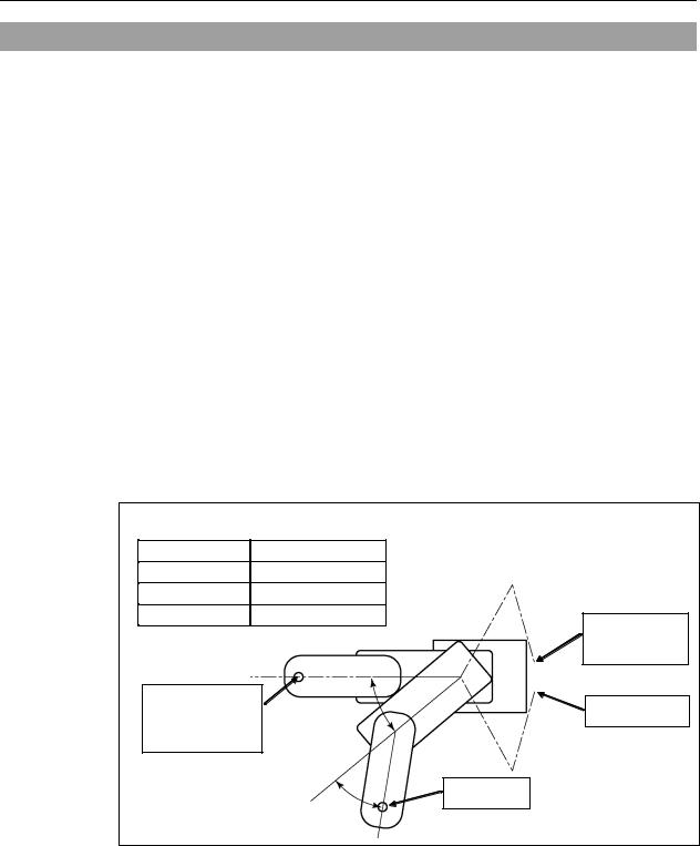
Free running distance in emergency
The operating Manipulator cannot stop immediately after the Emergency Stop switch is pressed.
The free running time/angle/distance of the Manipulator are shown below. However, remember that the values vary depending on following conditions.
Weight of the end effector Weight of work piece Operating pose Weight Speed Accel etc.
Conditions for Measurement |
|
||
Accel Setting |
100 |
|
|
Speed Setting |
100 |
|
|
Load [kg] |
3 |
|
|
Weight Setting |
3 |
Start point of |
|
|
|
||
|
|
operation |
|
Point where the |
Joint #1 |
Target point |
|
emergency stop |
|||
|
|
||
signal is input |
|
|
|
|
|
Stop point |
|
|
Joint #2 |
|
|
|
Controller |
RC180 / RC620 |
||
|
|
|
||
|
Manipulator |
RS3-351* |
||
|
|
|
|
|
Free running time |
Joint #1 + Joint #2 |
[sec.] |
0.4 |
|
|
|
|
||
Joint #3 |
[sec.] |
0.2 |
||
|
||||
|
|
|
|
|
|
Joint #1 |
[deg.] |
50 |
|
Free running angle |
|
|
|
|
Joint #2 |
[deg.] |
30 |
||
|
|
|
||
|
Joint #1 + Joint #2 [deg.] |
80 |
||
|
|
|
|
|
Free running distance |
Joint #3 |
[mm] |
55 |
|
|
|
|
|
|
6 |
RS Rev.5 |

Setup & Operation 1. Safety
1.5 Emergency Movement Without Drive Power
When the system is placed in emergency mode, push the arm or joint of the Manipulator by hand as shown below:
Arm #1 ........... |
Push the arm by hand. |
Arm #2 ........... |
Push the arm by hand. |
Joint #3 .......... |
The joint cannot be moved up/down by hand until the |
|
electromagnetic brake applied to the joint has been released. |
|
Move the joint up/down while pressing the brake release |
|
button. |
Joint #4 ......... |
Rotate the shaft by hand. |
Joint #1 (rotating)
−Joint #2
+ |
(rotating) |
Base |
|
−
Base |
+ |
Arm #1
|
Arm #1 |
|
|
|
Arm #2 |
|
|
|
|
|
|
|
Arm #2 |
|
|
|
|
|
|
+ |
|
|
|
|
Joint #3 |
|
|
|
Joint #3 |
|
(up and down) |
|
− |
Shaft |
brake release button |
|
|
− |
+ |
|
|
|
|
|
|
|
|
|
|
|
Joint #4 |
|
|
|
|
|
(rotating) |
|
|
|
|
||||
NOTE |
Be careful of the shaft while the brake release button is pressed, |
||||
) |
because the shaft may be lowered by the weight of an end effector. |
||||
RS Rev.5 |
7 |
Setup & Operation 1. Safety
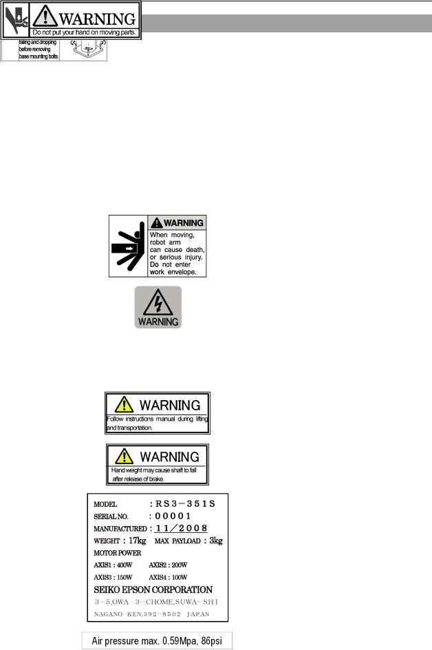
1.6 Manipulator Labels
The following labels are attached near the locations of the Manipulator where specific dangers exist.
Be sure to comply with descriptions and warnings on the labels to operate and maintain the Manipulator safely.
Do not tear, damage, or remove the labels. Use meticulous care when handling those parts or units to which the following labels are attached as well as the nearby areas:
|
|
|
Label |
|
NOTE |
|
|
|
|
|
Before loosening the base mounting screws, |
A |
|
|
|
|
hold the arm and secure it tightly with a band |
|
|
|
|
to prevent hands or fingers from being caught |
|
|
|
|
|
|
|
|
|
|
|
|
in the Manipulator. |
|
|
|
|
|
|
|
|
|
|
|
|
B |
|
|
|
|
|
|
|
|
|
|
|
|
|
|
|
|
Hazardous voltage exists while the |
C |
|
|
|
|
Manipulator is ON. To avoid electric shock, |
|
|
|
|
|
do not touch any internal electric parts. |
|
|
|
|
|
|
|
|
|
|
|
You can catch your hand or fingers between |
|
|
|
|
|
|
D |
|
|
|
|
the shaft and Arm #1 when bringing your |
|
|
|
|
|
hand close to moving parts. |
|
|
|
|
|
|
|
|
|
|
|
|
E |
|
|
|
|
|
|
|
|
|
|
|
|
|
|
|
|
|
|
|
|
|
|
|
|
|
|
|
|
|
F |
|
|
|
|
|
|
|
|
|
|
|
|
|
|
|
|
|
|
|
|
|
|
|
G |
|
|
|
|
|
|
|
|
|
|
|
H |
|
|
|
|
|
|
|
|
|
|
|
8 |
RS Rev.5 |
Setup & Operation 1. Safety
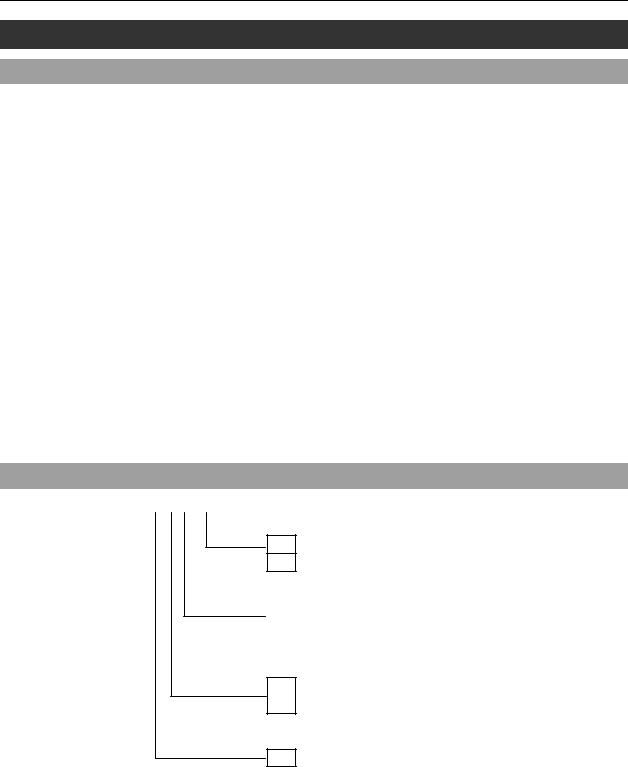
Location of Labels
H
C
C

 D
D


 C E
C E
F |
Top
Side
B (Both sides)
C
Front
G
Bottom
A 
RS Rev.5 |
9 |
Setup & Operation 2. Specifications
2.Specifications
2.1 Features of RS series Manipulators
The RS series Manipulators provides “Operation-oriented layout” with high-performance, high speed, high accuracy, space saving, and flexible installation.
The features of the RS series Manipulators are as follows:
Space Saving
Compactness achieved by using a ductless design
Small body and wide motion range
Ceiling mounting realizes the cylindrical motion range.
-Operation area: approx. 160 % (compared with Scara robot of same arm length)
-Max. inscribed : approx. 250 % (compared with Scara robot of same arm length)
Great flexibility for peripheral equipments installation
Access to ALL directions
Operation efficiency improvement
The shortcut motion with inward movement
2.2 Model Number
RS3-35 1 S -UL
UL specification
UL : UL compliant
□: Non UL compliant
Environment
S |
: Standard |
C |
: Cleanroom & ESD (Anti-static) |
Joint #3 stroke
1
: 130 mm
: 100 mm (with bellows)
Arm length
35 : 350 mm
Environment
Cleanroom-model
This model has additional features that reduce dust emitted by the Manipulator to enable use in clean room environments.
For details of the specifications, refer to Setup & Operation: 2.4 Specifications.
10 |
RS Rev.5 |
Setup & Operation 2. Specifications
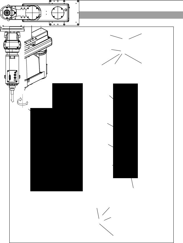
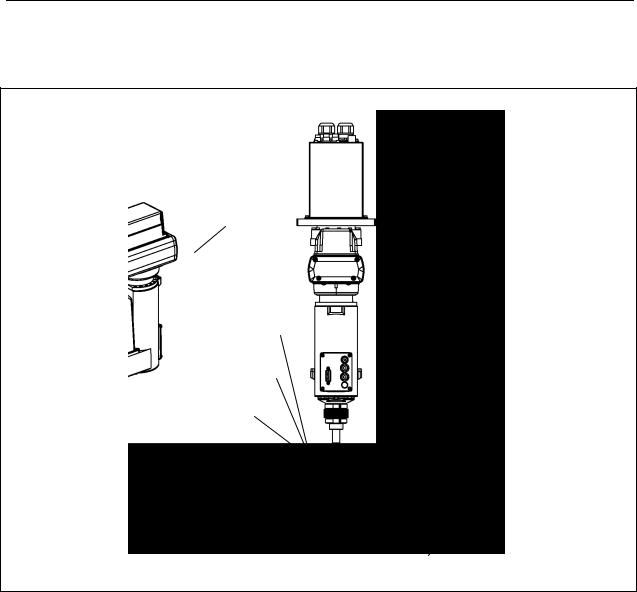
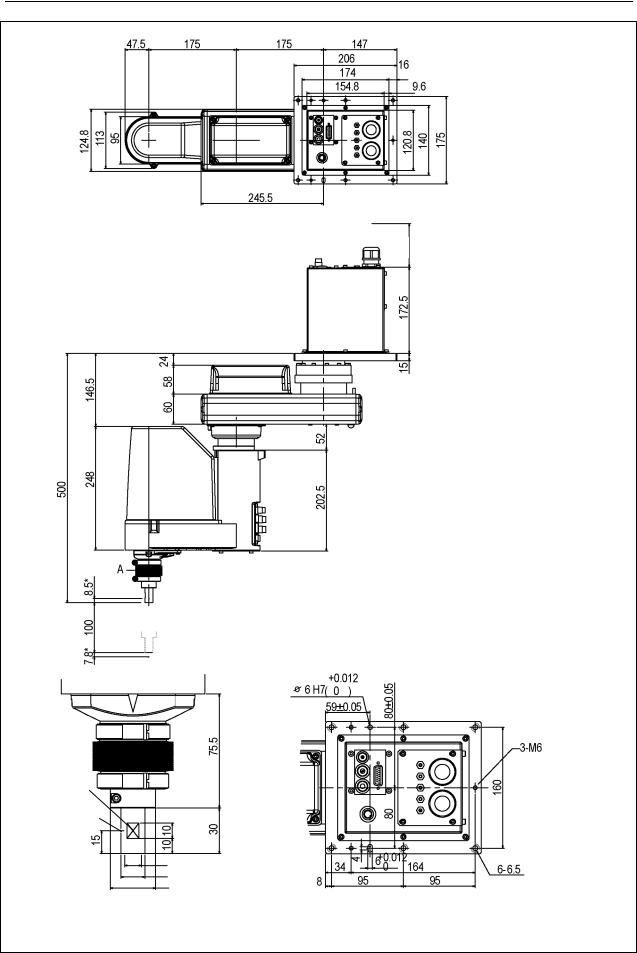
2.3 Part Names and Outer Dimensions
Standard-model: RS3-351S
|
|
Power Cable |
|
|
Signal Cable |
|
|
User Connector |
|
|
|
|
(15-pin D-sub Connector) |
|
|
||
|
Fitting (white) |
|
|
Fitting (white) |
|
|
Fitting (black) |
||||
|
for ø6 mm |
||||
|
|
for ø4 mm |
for ø6 mm |
pneumatic tube |
|
Joint #1 |
|
pneumatic tube |
pneumatic tube |
|
|
(rotating) |
|
|
|
|
|
− |
Joint #2 |
Power Cable |
Signal Cable |
||
|
|
|
|
|
|
+ |
(rotating) |
Base |
|
|
|
− |
|
|
|
||
|
|
|
|
|
|
Base |
+ |
|
|
|
|
Arm #1
Arm #1 |
|
|
|
|
Arm #2 |
Fitting (white) |
||||||
|
|
|
|
|
|
|||||||
|
|
|
|
|
|
|
|
|
|
|
|
|
|
|
|
|
|
|
|
|
|
|
|
|
for ø4 mm |
|
|
|
|
|
|
|
|
|
|
|
|
pneumatic tube |
Arm #2 |
|
|
|
|
|
|
|
|
|
|
Fitting (black) |
|
|
|
|
|
|
|
|
|
|
|
for ø6 mm |
||
|
|
+ |
|
|
User Connector |
|||||||
|
|
|
|
pneumatic tube |
||||||||
Joint #3 |
|
|
|
(15-pin D-sub Connector) |
Fitting (white) |
|||||||
|
− |
|
|
|
|
|
|
|
|
|||
(up and down) |
|
Shaft |
|
|
|
|
|
|
|
for ø6 mm |
||
|
|
− |
+ |
|
|
|
|
|
|
|
|
pneumatic tube |
|
|
|
|
|
|
|
|
|
|
Joint #3 and #4 |
||
|
|
|
|
|
|
|
|
|
|
|
||
|
|
|
Joint #4 |
|
|
|
|
|
|
|
|
brake release button |
|
|
|
(rotating) |
|
|
|
|
|
|
|
|
|
|
|
|
|
|
|
|
|
|
|
|
|
|
|
|
|
|
|
CE label |
|
|
|
|
|
MT label (only for custom specification) |
|
|
|
|
|
|
|
|
|
|
|
|
Signature label |
|
|
|
|
|
|
|
|
|
|
|
|
||
|
|
|
|
|
|
|
|
|
|
|
||
|
|
|
|
|
|
|
|
|
|
|
||
|
|
|
|
|
|
|
|
|
|
|
(Serial No. of Manipulator) |
|
|
|
|
|
|
|
|
|
|
|
|
||
|
|
|
|
|
|
|
|
|
|
|
||
|
|
|
|
|
|
|
|
|
|
|
UR label |
|
|
|
|
|
|
|
|
|
|
|
|
|
|
|
|
|
|
|
|
|
|
|
|
|
|
|
- When the brake release button is pressed in emergency mode, the Joints #3 brake will be
)- released.When the LED lamp is lighting or the controller power is on, the current is being applied to the manipulator. Performing any work with the power ON is extremely
hazardous and it may result in electric shock and/or improper function of the robot
system. Make sure to turn OFF the controller power before the maintenance work.NOTE
RS Rev.5 |
11 |

Setup & Operation 2. Specifications
90 or more Space for cables
← Manipulator installation position
(*) indicates the stroke margin by mechanical stop.
1 mm flat cu |
|
through hole |
|
|
|
||
Ø3,90° |
|
|
|
Conical hole |
|
|
|
Max.ø11 through hole |
|
For manipulator mounting |
|
ø16h7 shaft diameter |
|
||
|
through hole |
||
ø30 mechanical stop diameter |
|||
ø11 spot facing |
|||
Enlarged view from A |
Reference through hole |
||
depth 6.5 |
|||
(Original orientation of Joint #3, #4) |
(View from the top of the base) |
|
|
|
|
||
12 |
RS Rev.5 |
Setup & Operation 2. Specifications
Cleanroom-model: RS3-351C
The following figures show the special parts for Cleanroom-model (Table Top mounting). These parts are different in appearance from Standard-model.
Exhaust port |
Exhaust port |
Plate cover (For Anti-static)
Bellows |
Bellows |
|
RS Rev.5 |
13 |
Setup & Operation 2. Specifications
90 or more Space for cables
← Manipulator installation position
(*) indicates the stroke margin by mechanical stop.
|
|
through hole |
|
1 mm flat cu |
|
|
|
Ø3,90° |
|
|
|
Conical hole |
|
|
|
Max.ø11 through hole |
For Manipulator mounting |
||
through hole |
|||
ø16h7 Shaft diameter |
|||
|
|||
ø30 Mechanical stop diameter |
Ø11 spot facing |
||
Enlarged view from A |
Reference through hole |
depth 6.5 |
|
(Original orientation of Joint #3, #4) |
(View from the top of the base) |
from back side |
|
14 |
RS Rev.5 |

|
|
|
|
|
Setup & Operation 2. Specifications |
|
|
|
|
|
|
|
2.4 Specifications |
|
|||
|
|
|
|
|
|
|
|
|
Item |
|
RS series |
|
Arm length |
|
Arm #1, #2 |
350 mm |
|
|
|
Arm #1 |
175 mm |
||
|
|
|
|
Arm #2 |
175 mm |
|
Max. |
|
Joints #1, #2 |
6237 mm/s |
|
|
|
Joints # 3 |
1100 mm/s |
||
|
operating speed *1 |
||||
|
Joint #4 |
2600 deg/s |
|||
|
|
|
|
||
|
Repeatability |
|
Joints #1, #2 |
± 0.01 mm |
|
|
|
Joints # 3 |
± 0.01 mm |
||
|
|
|
|
Joint #4 |
± 0.01 deg |
|
Payload (Load) |
|
Rated |
1 kg |
|
|
|
Max. |
3 kg |
||
|
|
|
|
||
|
Joint #4 allowable |
|
Rated |
0.005 kg m2 |
|
|
moment of inertia *2 |
Max. |
0.05 kg m2 |
||
|
|
|
|
Joint #1 |
± 225 deg |
|
Max. |
|
Joint #2 |
± 225 deg |
|
|
|
|
RS3-351S: 130 mm |
||
|
motion range |
|
Joint #3 |
||
|
|
RS3-351C: 100 mm |
|||
|
|
|
|
|
|
|
|
|
|
Joint #4 |
± 720 deg |
|
|
|
|
Joint #1 |
− 2560000 to + 5973334 pulse |
|
Max. |
|
Joint #2 |
± 4177920 pulse |
|
|
pulse range |
|
Joint #3 |
RS3-351S: − 1479112 pulse to 0 pulse |
|
|
(pulse) |
|
RS3-351C: − 1137778 pulse to 0 pulse |
||
|
|
Joint #4 |
|||
|
|
|
|
± 3145728 pulse |
|
|
|
|
|
Joint #1 |
0.0000527 deg/pulse |
|
Resolution |
|
Joint #2 |
0.0000538 deg/pulse |
|
|
|
Joint #3 |
0.0000879 mm/pulse |
||
|
|
|
|
||
|
|
|
|
Joint #4 |
0.000229 deg/pulse |
|
Hand diameter |
|
Mounting |
ø 16 mm |
|
|
|
Hollow |
ø 11 mm |
||
|
|
|
|
||
|
Mounting hole |
|
|
6-M6 |
|
|
Weight (cables not included) |
17 kg: 38 lb |
|||
|
(Common to Standard & Cleanroom-model) |
||||
|
|
|
|
|
|
|
Driving method |
|
|
AC servo motor |
|
|
|
|
|
Joint #1 |
400 W |
|
Motor power |
|
Joint #2 |
200 W |
|
|
consumption |
|
Joint #3 |
150 W |
|
|
|
|
|
Joint #4 |
100 W |
|
Option |
|
Environment |
Cleanroom *3 & ESD |
|
|
Joint #3 down force |
|
150 N |
||
|
Installed wire for customer use |
15 wires: D-sub / 15 pin connectors |
|||
|
Installed pneumatic tube for customer use |
2 pneumatic tubes (ø 6 mm): 0.59 Mpa (6 kgf/cm2 : 86 psi) |
|||
|
1 pneumatic tube (ø 4 mm): 0.59 Mpa (6 kgf/cm2 : 86 psi) |
||||
|
Environmental |
|
Ambient temperature |
5 to 40°C (with minimum temperature variation) |
|
|
|
Ambient relative |
|
||
|
requirements |
|
10 to 80% RH (no condensation) |
||
|
|
humidity |
|||
|
|
|
|
||
|
Noise level *4 |
|
|
|
LAeq = 70 dB (A) |
|
Applicable Controller |
|
RC180, RC620 |
||
RS Rev.5 |
15 |

Setup & Operation 2. Specifications
|
Item |
RS series |
|
|
|
SPEED |
1 to (5) to100 |
|
|
ACCEL *5 |
1 to (10) to 120 |
Assignable Value |
|
SPEEDS |
1 to (50) to 2000 |
( ) Default values |
|
ACCELS |
1 to (200) to 25000 |
|
|
FINE |
0 to (10000) to 65000 |
|
|
WEIGHT |
0,175 to (1,175) to 3,175 |
MTBF |
|
|
3 years |
|
|
|
UL1740 (Third Edition, Dated December 7, 2007) |
|
|
|
ANSI/RIA R15.06-1999 |
Safety standard |
|
|
NFPA 79 (2007 Edition) |
|
|
CSA/CAN Z434-03 (February 2003) |
|
|
|
|
|
|
|
|
CE Marking − |
|
|
|
Machinery Directive, Low Voltage Directive, EMC Directive |
*1: In the case of PTP command. Maximum operating speed for CP command is 2000 mm/s on horizontal plane.
*2: In the case where the center of gravity is at the center of Joint #4.
If the center of gravity is not at the center of Joint #4, set the parameter using Inertia command.
*3: The exhaust system in the Cleanroom-model Manipulator draws air from the base interior and arm cover interior together.
A crack or other opening in the base unit can cause loss of negative air pressure in the outer part of the arm, which can cause increased dust emission.
Do not remove the maintenance cover on the front of the base.
Seal the exhaust port and the exhaust tube with vinyl tape so that the joint is airtight.
If the exhaust flow is not sufficient, dust particle emission may exceed the specified maximum level. Cleanliness level: Class ISO 3 (ISO14644-1)
In previous criteria; Clean Class: 10 or its equivalent
|
Amount of Dust (0.1 µm diameter or larger) in 28317 cm3 (1cft) |
|
sample-air around the center of the motion rang: 10 particles or |
|
less.) |
Exhaust System: Exhaust port diameter: Inner diameter: ø12 mm / Outer diameter: ø16 mm |
|
Exhaust tube |
: Polyurethane tube |
|
Outer diameter: ø12 mm (Inner diameter: ø8 mm) |
or Inner diameter ø16mm or larger
Recommended exhaust flow rate: approx. 1000 cm3/s (Normal)
*4: Conditions of Manipulator during measurement as follows:
Operating conditions : Under rated load, 4-joints simultaneous motion, maximum speed, maximum acceleration, and duty 50%.
Measurement point : In front of the Manipulator, 1000 mm apart from the motion range, 50 mm above the base-installed surface.
*5: In general use, Accel setting 100 is the optimum setting that maintains the balance of acceleration and vibration when positioning.
However, you may require an operation with high acceleration to shorten the cycle time by decreasing the vibration at positioning. In this case, set Accel to larger than 100.
If you specify a larger Accel value, the frequency of the overload error and over heat may rise during continuous operation. The use of large Accel setting is recommended only for necessary motions.
16 |
RS Rev.5 |
Setup & Operation 2. Specifications
2.5 How to Set the Model
The Manipulator model for your system has been set before shipment from the factory. It is normally not required to change the model when you receive your system.
■When you need to change the setting of the Manipulator model, be sure to set the Manipulator model properly. Improper setting of the Manipulator model may
result in abnormal or no operation of the Manipulator and/or cause safety CAUTION problems.
)specifications. The custom specifications may require a different configuration procedure; check the custom specifications number described on the MT label and contact us when necessary.
The Manipulator model can be set from software.
Refer to the chapter Robot Configuration in the EPSON RC+ User’s Guide.NOTE If an MT label is attached to the rear of a Manipulator, the Manipulator has custom
RS Rev.5 |
17 |

Setup & Operation 3. Environments and Installation
3.Environments and Installation
3.1 Environmental Conditions
A suitable environment is necessary for the robot system to function properly and safely. Be sure to install the robot system in an environment that meets the following conditions:
Item |
|
|
Conditions |
Ambient temperature *1 |
5 to 40°C |
(with minimum temperature variation) |
|
Ambient relative humidity |
10 to 80% |
(no condensation) |
|
First transient burst noise |
2 kV or less |
|
|
Electrostatic noise |
6 kV or less |
|
|
|
· |
Install indoors |
|
|
· |
Keep away from direct sunlight |
|
|
· |
Keep away from dust, oily smoke, salinity, |
|
|
|
metal powder or other contaminants |
|
Environment |
· |
Keep away from flammable or corrosive solvents |
|
|
|
and gases |
|
|
· |
Keep away from water |
|
|
· |
Keep away from shocks or vibrations |
|
|
· |
Keep away from sources of electric noise |
|
|
|
|
|
)etc. When using Manipulators in inadequate environments that do not meet the above conditions, please contact us.NOTE Manipulators are not suitable for operation in harsh environments such as painting areas,
*1 The ambient temperature conditions are for the Manipulators only. For the Controller the Manipulators are connected to, refer to the Controller manual.
3.2 Base Table
A base table for anchoring the Manipulator is not supplied. Please make or obtain the base table for your Manipulator. The shape and size of the base table differs depending on the use of the robot system. For your reference, we list some Manipulator table requirements here.
The base table must not only be able to bear the weight of the Manipulator but also be able to withstand the dynamic movement of the Manipulator when the Manipulator operates at maximum acceleration. Ensure that there is enough strength on the base table by attaching reinforcing materials such as crossbeams.
The torque and reaction force produced by the movement of the Manipulator are as follows:
Max. Reaction torque on the horizontal plate : |
500 Nm |
|
Max. Horizontal reaction force |
: |
1200 N |
Max. Vertical reaction force |
: 1100 N |
|
The threaded holes required for mounting the Manipulator base are M6. Use mounting bolts with specifications conforming to ISO898-1 property class: 10.9 or 12.9.
For dimensions, refer to Setup & Operation: 3.3 Mounting Dimensions.
18 |
RS Rev.5 |
Loading...