


RC170
Table of contents
 Loading...
Rev.1a EM068P1378F
RC170 Option
Operator Panel
OP1

ii
RC170 Option Operator Panel OP1 Rev.1a

OP1 Rev.1a i
RC170 Option
Operator Panel
OP1
Rev.1a
Copyright © 2006 SEIKO EPSON CORPORATION. All rights reserved.

ii OP1 Rev.1a
FOREWORD
Thank you for purchasing our robot products.
This manual contains the information necessary for the correct use of the Operator Panel.
Please carefully read this manual and other related manuals before installing the robot
system.
Keep this manual handy for easy access at all times.
WARRANTY
The robot system and its optional parts are shipped to our customers only after being
subjected to the strictest quality controls, tests, and inspections to certify its compliance
with our high performance standards.
Product malfunctions resulting from normal handling or operation will be repaired free of
charge during the normal warranty period. (Please ask your Regional Sales Office for
warranty period information.)
However, customers will be charged for repairs in the following cases (even if they occur
during the warranty period):
1. Damage or malfunction caused by improper use which is not described in the manual,
or careless use.
2. Malfunctions caused by customers’ unauthorized disassembly.
3. Damage due to improper adjustments or unauthorized repair attempts.
4. Damage caused by natural disasters such as earthquake, flood, etc.
Warnings, Cautions, Usage:
1. If the robot system associated equipment is used outside of the usage conditions an
d
product specifications described in the manuals, this warranty is void.
2. If you do not follow the WARNINGS and CAUTIONS in this manual, we cannot be
responsible for any malfunction or accident, even if the result is injury or death.
3. We cannot foresee all possible dangers and consequences. Therefore, this manual
cannot warn the user of all possible hazards.

OP1 Rev.1a iii
TRADEMARKS
Microsoft, Windows, and Windows logo are either registered trademarks or trademarks of
Microsoft Corporation in the United States and/or other countries. Other brand and
product names are trademarks or registered trademarks of the respective holders.
TRADEMARK NOTATION IN THIS MANUAL
Microsoft® Windows® XP Operating system
Microsoft® Windows® 2000 Operating system
Throughout this manual, Windows XP, and Windows 2000 refer to above respective
operating systems. In some cases, Windows refers generically to Windows XP, and
Windows 2000.
NOTICE
No part of this manual may be copied or reproduced without authorization.
The contents of this manual are subject to change without notice.
Please notify us if you should find any errors in this manual or if you have any comments
regarding its contents.
INQUIRIES
Contact the following service center for robot repairs, inspections or adjustments.
If service center information is not indicated below, please contact the supplier office for
your region.
Please prepare the following items before you contact us.
- Your controller model and its serial number
- Your manipulator model and its serial number
- Software and its version in your robot system
- A description of the problem
SERVICE CENTER

iv OP1 Rev.1a
MANUFACTURER & SUPPLIER
Japan & Others
SEIKO EPSON CORPORATION
Suwa Minami Plant
Factory Automation Systems Dept.
1010 Fujimi, Fujimi-machi,
Suwa-gun, Nagano, 399-0295
JAPAN
TEL : +81-(0)266-61-1802
FAX : +81-(0)266-61-1846
SUPPLIERS
North & South America
EPSON AMERICA, INC.
Factory Automation/Robotics
18300 Central Avenue
Carson, CA 90746
TEL : +1-562-290-5900
FAX : +1-562-290-5999
E-MAIL : info@robots.epson.com
Europe
EPSON DEUTSCHLAND GmbH
Factory Automation Division
Otto-Hahn-Str.4
D-40670 Meerbusch
Germany
TEL : +49-(0)-2159-538-1391
FAX : +49-(0)-2159-538-3170
E-MAIL : robot.infos@epson.de
Before Reading This Manual
Do not connect the OP1 to the following Robot Controllers. Connecting to the following
Robot Controllers may result in malfunction of the device since the pin assignments are
different.
RC420 / RC520 / SRC5** / SRC-3** / SRC-2**
)
NOTE

OP1 Rev.1a v
TABLE OF CONTENTS
1. Safety 1
1.1 Conventions...................................................................................................1
1.2 Safety Precautions ........................................................................................1
1.3 Emergency Stop............................................................................................3
2. Specifications 4
2.1 Specification Tables ......................................................................................4
2.1.1 Electrical Specifications................................................................... 4
2.1.2 Environmental Specifications .......................................................... 4
2.1.3 Appearance Specifications.............................................................. 4
2.2 Part Names and Functions............................................................................5
2.3 Appearance and Dimensions ........................................................................6
2.3.1 Appearance (without mounting metal hasps) ................................. 7
2.3.2 Appearance (with mounting metal hasps)....................................... 7
2.3.3 Panel Cutout Dimensions................................................................ 8
2.3.4 Mounting Metal Hasps Dimensions ................................................ 8
3. Installation 9
3.1 Unpacking......................................................................................................9
3.2 Installation......................................................................................................9
3.2.1 Gasket................................................................................................. 9
3.2.2 Mounting Holes ................................................................................. 10
3.2.3 Installing Operator Panel .................................................................. 11
3.3 Connecting Cables......................................................................................12
3.4 Teach Pendant Connection.........................................................................13
4. Operation 14
4.1 Basic Operations .........................................................................................14
4.2 Startup Screen.............................................................................................15
4.3 Program Execution Screen .........................................................................16
4.4 Task Monitor Screen ...................................................................................19
4.5 I/O Monitor Screen ......................................................................................20
4.6 System History Screen ................................................................................22
4.7 Application Screen ......................................................................................23
4.8 Setup Screen...............................................................................................25

vi OP1 Rev.1a
5. Programming for Operator Panel 27
5.1 Display on Operator Panel ..........................................................................27
5.1.1 Simple Display Program.................................................................27
5.1.2 Display Device................................................................................28
5.2 Data Input from Operator Panel.................................................................. 28
5.2.1 Value Input ......................................................................................29
5.2.2 String Input......................................................................................30
5.3 About Display Language ............................................................................. 31
6. Maintenance and Inspection 32
6.1 Contrast Adjustment.................................................................................... 32
6.2 Brightness Adjustment ................................................................................ 33
6.3 Firmware Update.........................................................................................34
6.4 Case and Display Cleaning......................................................................... 34
6.5 About Gasket............................................................................................... 35
6.6 Regular Maintenance Inspection ................................................................36
6.7 Backlight Replacement ...............................................................................36
6.8 Maintenance Parts List................................................................................ 36
1. Safety
OP1 Rev.1a 1
1. Safety
1.1 Conventions
Important safety considerations are indicated throughout the manual by the following
symbols. Be sure to read the descriptions shown with each symbol.
WARNING
This symbol indicates that a danger of possible serious injury or
death exists if the associated instructions are not followed
properly.
WARNING
This symbol indicates that a danger of possible harm to people
caused by electric shock exists if the associated instructions are
not followed properly.
CAUTION
This symbol indicates that a danger of possible harm to people or
physical damage to equipment and facilities exists if the
associated instructions are not followed properly.
1.2 Safety Precautions
For details of Safety, refer to the User’s Guide 2. Safety. Please read and understand the chapter
before using the robot system.
Only trained personnel should design and install the robot system. Trained
personnel are defined as those who have taken robot system training and
maintenance training classes held by the manufacturer, dealer, or local
representative company, or those who understand the manuals thoroughly and
have the same knowledge and skill level as those who have completed the
training courses.
WARNING
Only authorized personnel who have taken the safety training should be allowed
to execute teaching or calibration of the robot system.
The safety training is the program for industrial robot operator that follows the
laws and regulations of each nation. The personnel who have taken the safety
training acquire knowledge of industrial robots (operations, teaching, etc.).
The personnel who have completed the robot system-training class held by the
manufacturer, dealer, or locally-incorporated company are allowed to maintain
the robot system.
1. Safety
2 OP1 Rev.1a
Only authorized personnel who have taken the safety training should be allowed
to maintain the robot system.
The safety training is the program for industrial robot operator that follows the laws
and regulations of each nation. The personnel who have taken the safety training
acquire knowledge of industrial robots (operations, teaching, etc.), knowledge of
inspections, and knowledge of related rules/regulations. The personnel who have
completed the robot system-training and maintenance-training classes held by
the manufacturer, dealer, or locally incorporated company are allowed to maintain
the robot system.
WARNING
Immediately press the EMERGENCY STOP switch whenever you suspect any
danger.
The Operator Panel is equipped with an EMERGENCY STOP switch. Before
operating the Operator Panel, make sure that the EMERGENCY STOP switch on
the Operator Panel functions properly. Operating the Operator Panel when the
switch does not function properly is extremely hazardous and may result in
serious bodily injury and/or serious damage to the equipment, as the switch
cannot fulfill its intended function in an emergency.
WARNING
Be sure to connect the cables between the Controller and the Operator Panel
properly. Do not allow unnecessary strain on the cables. (Do not put heavy
objects on the cables. Do not bend or pull the cables forcibly.) The unnecessary
strain on the cables may result in damage to the cables, disconnection, and/or
contact failure. Damaged cables, disconnection, or contact failure is extremely
hazardous and may result in electric shock and/or improper function of the
system. Do not use the cables near heat or fire.
Do not shock the Operator Panel physically or place any object on Operator
Panel. A liquid crystal display is used for the Operator Panel display. If the
display is damaged, liquid crystal may leak out. Liquid crystal is harmful. If it
sticks on your skin or clothes, immediately wash your skin and clothes thoroughly
with clean water and soap immediately.
The Operator Panel must be used within the environmental conditions described
in this manual. This product has been designed and manufactured strictly for use
in a normal indoor environment. Using this product in the environment that
exceeds the conditions may not only shorten the life cycle of the product but also
cause serious safety problems.
Do not disassemble, repair, or modify the Operator Panel by yourself. Improper
disassembly, repair, or modification of the Operator Panel may cause not only
improper function of the robot system but also serious safety problems.
CAUTION
Be sure to turn OFF the Controller before connecting and disconnecting cables.
Connecting or disconnecting the cables with the power ON may result in
malfunction of the robot system.
1. Safety
OP1 Rev.1a 3
1.3 Emergency Stop
WARNING
Immediately press the EMERGENCY STOP switch whenever you suspect any
danger.
The Operator Panel is equipped with an EMERGENCY STOP switch. Before
operating the Operator Panel, make sure that the EMERGENCY STOP switch
on the Operator Panel functions properly. Operating the Operator Panel when
the switch does not function properly is extremely hazardous and may result in
serious bodily injury and/or serious damage to the equipment, as the switch
cannot fulfill its intended function in an emergency.
Furthermore, the EMERGENCY STOP switch does not function when nothing is
displayed on the Operator Pendant screen for the disconnection of the Operator
Pendant to the Controller.
Press the EMERGENCY STOP switch to stop the program execution, and turn OFF the
robot axis motors. The program, pause data and other data will not be destroyed.
When the EMERGENCY STOP switch is pressed, the Emergency Stop state is held both
mechanically and electrically.
To resume operation, follow the procedure below to reset the emergency stop state.
How to Reset an Emergency Stop State
(1) Remove the cause of the Emergency Stop, and make sure that the robot can be operated
safely when robot operation is resumed.
(2) Release the EMERGENCY STOP switch. To release a mechanical hold, turn the
EMERGENCY STOP switch to the right.
(3) Display the program execution screen and touch the Reset button.
When the Emergency Stop is released, the “EMERGENCY STOP” on the Operator Panel
Program Execution Screen turns OFF (displays
).
2. Specifications
4 OP1 Rev.1a
2. Specifications
2.1 Specification Tables
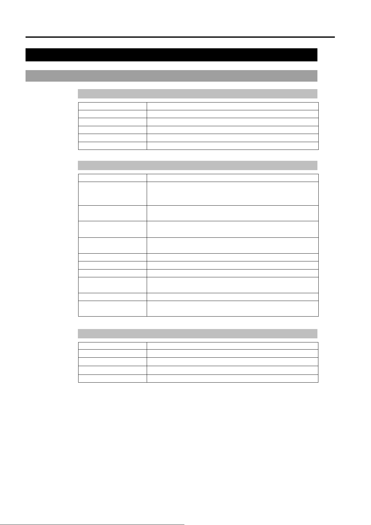
2.1.1 Electrical Specifications
Item Specifications
Rated voltage DC 24 V
Voltage range DC 21.6 to 26.4 V
Power consumption 7 W or less
Dielectric strength AC 500 V 20 mA per minute (across charger and FG terminals)
Insulation resistance 500 VDC 20 MΩ or more (across charger and FG terminals)
2.1.2 Environmental Specifications
Item Specifications
Ambient temperature
(in panel and at sides of
display screen)
5 to 40 deg C (with minimal variation)
Storage ambient
temperature
−25 to 55 deg C
Operating ambient
humidity
20 to 80% (no condensation)
Storage ambient
humidity
20 to 80% (no condensation)
Dust 0.1 mg/m
3
or less (no conductive dust)
Contamination level 2
Corrosive gasses Free of corrosive gasses
Air pressure resistance
(operation altitude)
800 to 1114 hPa (Max. 2000 m)
Noise resistance 1 kV (EN61000-4-4)
Electrostatic discharge
immunity
4 kV (EN61000-4-2 level 2)
2.1.3 Appearance Specifications
Item Specifications
Protective structure* JEM1030 IP65 or equivalent NEMA#250 TYPE4X/12
External dimensions
W215 mm × H155 mm × D46 mm (excluding connector hood)
Weight
Approx. 800 g (Including Bypass Plug. Excluding the cable.)
Cooling method Air-cooling without blower
* The protective structure is for the front part when the Operator Panel is installed. Though
conformity has been confirmed under applicable testing conditions, use under all
environments is not guaranteed. Before you start to use the Operator Panel, confirm use
in the operating environment. Also, gasket that is used for long periods of time or once
has been installed on the panel is scratched or dirty, and may cause lose sufficient
protection performance. To ensure consistent protection performance, replace the gasket
periodically.
2. Specifications
OP1 Rev.1a 5
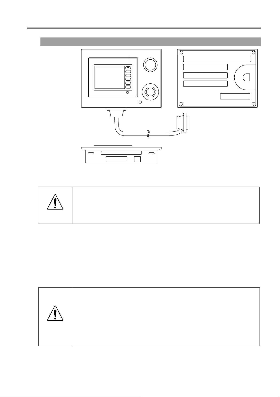
2.2 Part Names and Functions
(1)
(3)
(4)
(6)
(7)
(8)
(9)
(2)
(5)
(8)
(10)
(1) Touch Panel
This screen displays various information, and is used for automatic operation, data entry,
and other operations.
WARNING
When the backlight of the touch panel goes out, the screen turns completely black
and you can no longer see what is on the screen. The touch switches, however,
are enabled. When nothing is displayed on the LCD screen even though the
power lamp is ON, the backlight may have gone out. Stop to use it immediately
and repair the Operator Panel.
(2) Function switches
These switches are used for entering data from the Operator Panel.
(3) EMERGENCY STOP switch
This switch is for Emergency Stop. When this switch is pressed, the Emergency Stop state is
held both mechanically and electrically. When an emergency stop is performed, the motor
for each manipulator axis turns OFF and the robot stops immediately.
For details on how to release an Emergency Stop, refer to 1.3 Emergency Stop.
WARNING
Immediately press the EMERGENCY STOP switch whenever you suspect any
danger.
The Operator Panel is equipped with an EMERGENCY STOP switch. Before
operating the Operator Panel, make sure that the EMERGENCY STOP switch on
the Operator Panel functions properly. Operating the Operator Panel when the
switch does not function properly is extremely hazardous and may result in
serious bodily injury and/or serious damage to the equipment, as the switch
cannot fulfill its intended function in an emergency.
2. Specifications
6 OP1 Rev.1a
(4) Power Lamp
This lights (green) when the controller's power switch is turned ON.
(5) Teach Pendant connector (Bypass Plug)
This connector is for connecting the optional Teach Pendant for Robot Controller RC170.
When the Teach Pendant does not need to be connected, connect the Bypass Plug. The
robot status will be the Emergency Stop state unless the Teach Pendant or Bypass Plug is
connected.
WARNING
To ensure that the dust and drip-proof function properly, be sure to attach the
Bypass Plug when the Teach Pendant is not connected. Make sure to secure the
Teach Pendant connect or the Bypass Plug.
(6)
Controller connector
This connector connects the cable from the Operator Panel to the Controller.
(D-Sub 25-pin)
(7) HCOM connector
This connector is for connecting the high-speed communications connector. (RJ45)
(8) Mounting metal hasp
These metal hasps are for installing the Operator Panel on a panel.
2 holes both at top and bottom (total 4 locations)
(9) TOOL connector
This connector is for connecting the communications cable to change the display firmware.
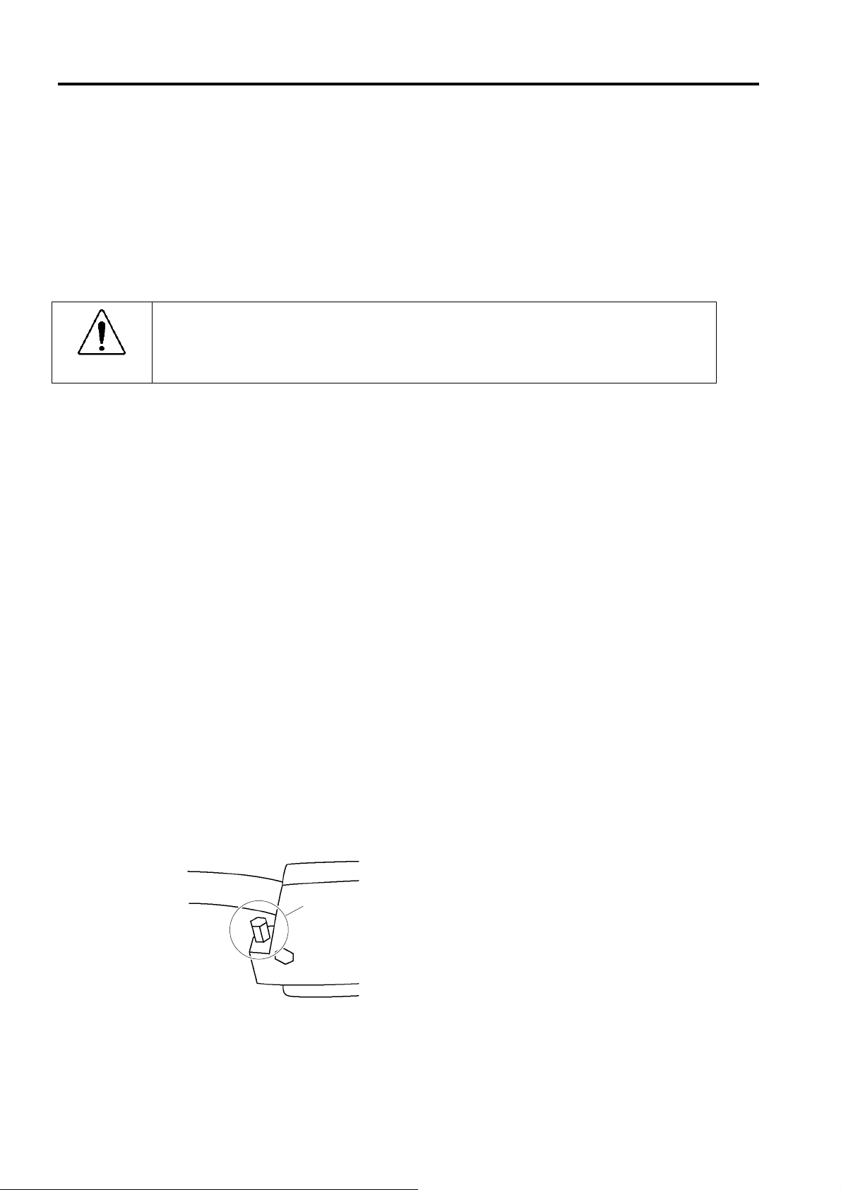
(10) OP1 cable
Connects the straight connector to the Operator Panel and right angle connector to the
RC170.
Secure the connector on the RC170 side with hexagon head screws.
Hexagon Head Screw
(on both side of the connector)
RC170 Side Connector
Loading...