


4400
Table of contents
 Loading...
SERVICE MANUAL
Color Large Format Inkjet Printer
EPSON Stylus Pro 4400/4450/4800 4880/4880C
SEIJ04008

Notice:
All rights reserved. No part of this manual may be reproduced, stored in a retrieval system, or transmitted in any form or by any means,
electronic, mechanical, photocopying, recording, or otherwise, without the prior written permission of SEIKO EPSON CORPORATION.
The contents of this manual are subject to change without notice.
All effort have been made to ensure the accuracy of the contents of this manual. However, should any errors be detected, SEIKO EPSON
would greatly appreciate being informed of them.
The above not withstanding SEIKO EPSON CORPORATION can assume no responsibility for any errors in this manual or the consequences
thereof.
EPSON is a registered trademark of SEIKO EPSON CORPORATION.
General Notice: Other product names used herein are for identification purpose only and may be trademarks or registered trademarks of their
respective owners. EPSON disclaims any and all rights in those marks.
Copyright © 2007 SEIKO EPSON CORPORATION.
Imaging Product CS,PL & Environmental Management

PRECAUTIONS
Precautionary notations throughout the text are categorized relative to 1)Personal injury and 2) damage to equipment.
DANGER Signals a precaution which, if ignored, could result in serious or fatal personal injury. Great caution should be exercised in
performing procedures preceded by DANGER Headings.
WARNING Signals a precaution which, if ignored, could result in damage to equipment.
The precautionary measures itemized below should always be observed when performing repair/maintenance procedures.
DANGER
1. ALWAYS DISCONNECT THE PRODUCT FROM THE POWER SOURCE AND PERIPHERAL DEVICES PERFORMING ANY MAINTENANCE
OR REPAIR PROCEDURES.
2. NO WORK SHOULD BE PERFORMED ON THE UNIT BY PERSONS UNFAMILIAR WITH BASIC SAFETY MEASURES AS DICTATED FOR
ALL ELECTRONICS TECHNICIANS IN THEIR LINE OF WORK.
3. WHEN PERFORMING TESTING AS DICTATED WITHIN THIS MANUAL, DO NOT CONNECT THE UNIT TO A POWER SOURCE UNTIL
INSTRUCTED TO DO SO. WHEN THE POWER SUPPLY CABLE MUST BE CONNECTED, USE EXTREME CAUTION IN WORKING ON
POWER SUPPLY AND OTHER ELECTRONIC COMPONENTS.
WARNING
1. REPAIRS ON EPSON PRODUCT SHOULD BE PERFORMED ONLY BY AN EPSON CERTIFIED REPAIR TECHNICIAN.
2. MAKE CERTAIN THAT THE SOURCE VOLTAGES IS THE SAME AS THE RATED VOLTAGE, LISTED ON THE SERIAL NUMBER/RATING
PLATE. IF THE EPSON PRODUCT HAS A PRIMARY AC RATING DIFFERENT FROM AVAILABLE POWER SOURCE, DO NOT CONNECT IT
TO THE POWER SOURCE.
3. ALWAYS VERIFY THAT THE EPSON PRODUCT HAS BEEN DISCONNECTED FROM THE POWER SOURCE BEFORE REMOVING OR
REPLACING PRINTED CIRCUIT BOARDS AND/OR INDIVIDUAL CHIPS.
4. IN ORDER TO PROTECT SENSITIVE MICROPROCESSORS AND CIRCUITRY, USE STATIC DISCHARGE EQUIPMENT, SUCH AS ANTISTATIC WRIST STRAPS, WHEN ACCESSING INTERNAL COMPONENTS.
5. REPLACE MALFUNCTIONING COMPONENTS ONLY WITH THOSE COMPONENTS BY THE MANUFACTURE; INTRODUCTION OF
SECOND-SOURCE ICs OR OTHER NON-APPROVED COMPONENTS MAY DAMAGE THE PRODUCT AND VOID ANY APPLICABLE EPSON
WARRANTY.
6. WHEN AIR DUSTRE IS USED ON THE REPAIR AND THE MAINTENANCE WORK, THE USE OF THE AIR DUSTER PRODUCTS
CONTAINING THE INFLAMMABLE GAS IS PROHIBITED.

About This Manual
This manual describes basic functions, theory of electrical and mechanical operations, maintenance and repair procedures of the printer. The instructions and
procedures included herein are intended for the experienced repair technicians, and attention should be given to the precautions on the preceding page.
Manual Configuration
This manual consists of six chapters and Appendix.
CHAPTER 1.PRODUCT DESCRIPTIONS
Provides a general overview and specifications of the product.
CHAPTER 2.OPERATING PRINCIPLES
Describes the theory of electrical and mechanical operations of
the product.
CHAPTER 3.TROUBLESHOOTING
Describes the step-by-step procedures for the troubleshooting.
CHAPTER 4.DISASSEMBLY / ASSEMBLY
Describes the step-by-step procedures for disassembling and
assembling the product.
CHAPTER 5.ADJUSTMENT
Provides Epson-approved methods for adjustment.
CHAPTER 6.MAINTENANCE
Provides preventive maintenance procedures and the lists of
Epson-approved lubricants and adhesives required for servicing
the product.
APPENDIX Provides the following additional information for reference:
• Connector pin assignments
• Electrical circuit boards schematics
• Exploded diagram & Parts List
Symbols Used in this Manual
Various symbols are used throughout this manual either to provide ad ditional
information on a specific topic or to warn of possible danger present during a
procedure or an action. Be aware of all symbols when they are used, and
always read NOTE, CAUTION, or WARNING messages.
Indicates an operating or maintenance procedure, practice or
condition that is necessary to keep the product’s quality.
Indicates an operating or maintenance procedure, practice, or
condition that, if not strictly observed, could result in damage to,
or destruction of, equipment.
May indicate an operating or maintenance procedure, prac tice or
condition that is necessary to accomplish a task efficiently. It may
also provide additional information that is related to a specific
subject, or comment on the results achieved through a previous
action.
Indicates an operating or maintenance procedure, practice or
condition that, if not strictly observed, could result in injury or loss
of life.
Indicates that a parti cu la r ta sk mu st be ca rr i ed o ut ac co rd ing to a
certain standard after disassembly and before re-assembly,
otherwise the quality of the components in question may be
adversely affected.

Revision Status
Revision Date of Issue Description
A Jun. 2, 2005 First release
B May. 25, 2007 Revised contents:
[Chapter 3]
Recovery (p.163) was changed.
[Chapter 5]
• Procedures were partially changed in 5.1.4 Adjustment Items classified by Part/Unit (p.368).
• 5.8 Installing Firmware for SP 4400 (4-color model) after replacing Main Board with New one (p.445) was added.
C September. 12, 2007 Revised Contents:
[All chapters]
• Information on Stylus 4450/4880/4880C has been added.

EPSON Stylus Pro 4400/4450/4800/4880/4880C Revision C
Contents
Chapter 1 Product Description
1.1 Product Description............................................................................................. 10
1.1.1 Comparison with Stylus Pro 4000.................................... .......................... 10
1.1.2 Features....................................................................................................... 11
1.2 Basic Specifications......................................... .................................................... 13
1.2.1 Print Specifications............................................. ........................................ 13
1.2.2 Character Specification............................................................................... 14
1.2.3 Control Code....................................................... ................................. ....... 14
1.2.4 Paper Feed Specification ............................................................................ 14
1.2.5 Paper Feeder Specification......................................................................... 14
1.2.6 Paper Specification..................................................................................... 15
1.2.7 Mechanism Specifications.......................................................................... 19
1.2.8 Electrical Specification............................................................................... 22
1.2.9 Reliability ................................................................................................... 23
1.2.10 Environmental Conditions........................................................................ 23
1.2.11 Quality Standards for Completed Products .............................................. 25
1.2.12 Overall Dimensions.................................................................................. 25
1.2.13 Accessories............................................................................................... 26
1.3 External View and Parts Names.......................................................................... 28
1.4 Operating Panel ............................................ ....................................................... 30
1.4.1 Buttons and Functions ................................................................................ 30
1.4.2 Panel Display.............................................................................................. 33
1.4.3 Job information........................................................................................... 39
1.4.4 Panel Setting............................. .................................. ................................ 40
1.4.5 Maintenance Mode 1 .................................................................................. 83
1.4.6 Maintenance Mode 2 .................................................................................. 90
1.4.7 MIB Function............................................................................................ 102
1.4.8 Function to Prevent Irregular Printing...................................................... 103
1.4.9 Initialization.............................................................................................. 104
1.4.10 Default Setup Values.............................................................................. 104
1.5 Controller........................................................................................................... 105
1.6 Interface............................................................................................................. 106
1.6.1 USB interface............................................................................................ 106
1.6.2 IEEE1394 Interface ....................................................... ........................... 107
1.6.3 Optional Interface..................................................... ................................ 108
1.6.4 Supplements....................................... .................................. ..................... 110
1.7 Optional Units and Consumables................................................. ..................... 111
1.7.1 Ink Cartridge........................... .................................. ................................ 111
1.7.2 Cleaning cartridge..................................................................................... 112
1.7.3 Maintenance Tank .................................................................................... 112
Chapter 2 Operating Principles
2.1 Overview...................................... .................................................................... . 114
2.2 Printer Mechanism Components....................................................................... 115
2.2.1 Printing Mechanism (Print Head).......................... ................................... 116
2.2.2 Ink Supply Mechanism............................................. ................................ 118
2.2.3 Cleaning Mechanism................................................................................ 120
2.2.4 Carriage (CR) Mechanism........................................................................ 125
2.2.5 Paper Feed Mechanism............................................................................. 131
2.2.6 Paper Eject/Release Mechanism.............................................................. . 140
2.2.7 Multi Sensor ................................................................ ............................. 145
2.2.8 Others...................................... .................................. ................................ 151
2.3 Outline of Control Circuit Board............................................ ........................... 152
2.4 Outline of Power Supply Circuit Board ............................................................ 154
2.5 Colorimetric Calibration (Color ID) Overview....................................... .......... 155
6

EPSON Stylus Pro 4400/4450/4800/4880/4880C Revision C
Chapter 3 Troubleshooting
3.1 Outline............................................................................................................... 157
3.1.1 Check Before Troubleshooting ................................................................. 157
3.1.2 Narrow Down the Trouble........................................................................ 157
3.2 Troubleshooting Based on Panel Messages ...................................................... 158
3.2.1 Message Table.......................................................................................... 158
3.2.2 Corrective Actions for Displayed Warnings............................................. 162
3.2.3 Corrective Actions for Error Display ................................................ ....... 165
3.2.4 Corrective Actions for Service Request Display...................................... 175
3.3 Troubleshooting Based on Your Printout.......................................................... 196
Chapter 4 Disassembly & Assembly
4.1 Introductory Information................................................................................... 201
4.1.1 Cautions.................................................................................................... 201
4.1.2 Tools......................................................................................................... 203
4.1.3 Screws....................................................................................................... 204
4.1.4 Difference Between 8-color And 4-color Models In Disassembly/Assembly
205
4.2 Disassembly Procedures.................................................................................... 206
4.2.1 Basic Operations....................................................................................... 207
4.2.2 Consumable Parts/ASF Cassette Removal............................................... 209
4.2.3 Panel Unit/Housing Removal................................................................... 214
4.2.4 Circuit Board Removal............................................................................. 226
4.2.5 Printer Mechanism Disassembly .............................................................. 241
4.2.6 ASF........................................................................................................... 246
4.2.7 Carriage Mechanism................................................................................. 266
4.2.8 Ink System................................................................................................ 285
4.2.9 Paper Feed Mechanism ............................................................................. 343
4.2.10 Harness Routing...................................................................................... 358
4.2.11 Disassembly/Assembly Unique to 4-color Model (Stylus Pro 4000)..... 36 2
Chapter 5 Adjustment
5.1 Overview...................................... .................................................................... . 367
5.1.1 Cautions...................................................... ................................. ............. 367
5.1.2 Advance of Adjustment............................................................................ 367
5.1.3 The Part/Unit that Requires Adjustment .................................................. 367
5.1.4 Adjustment Items classified by Part/Unit................................................. 368
5.1.5 Adjustment Item .......................................................................... ............. 371
5.1.6 Adjustment Tools ................................. ... .................................. ............... 374
5.1.7 Adjustment Program Basic Operation...................................................... 375
5.2 Mechanical Adjustment........................................................................... .......... 376
5.2.1 CR Timing Belt Tension Adjustment....................................................... 376
5.2.2 PF Timing Belt Tension Adjustment........................................................ 378
5.2.3 Paper Thickness Sensor Adjustment ........................................................ 380
5.2.4 CR Encoder Sensor Position Adjustment................................................. 382
5.2.5 PG Adjustment .............................................................. ........................... 383
5.2.6 Multi Sensor Position Adjustment............................................................ 385
5.3 Basic Adjustment .............................................................................................. 387
5.3.1 RTC&USB ID&IEEE1394 ID ................................................................. 387
5.3.2 Head Rank ID.............................. ............................................................. 388
5.3.3 Multi Sensor Level Adjustment................................................................ 389
5.3.4 T&B&S (Roll Paper)................................................... ............................. 390
5.3.5 T&B&S (Cut Sheet) ................................................................................. 391
5.3.6 Cutter Pressure Adjustment...................................................................... 392
5.3.7 Nozzle Bi-D Adjustment .......................................................................... 393
5.3.8 Print Head Slant Adjustment (PF)........................................................... . 394
5.3.9 Print Head Slant Adjustment (CR)........................................................... 397
5.3.10 Auto Uni-d Adjustment.......................................................................... 401
5.3.11 Multi Sensor Adjustment for Auto Nozzle Check.................................. 402
5.3.12 Skew Check............................................................................................ 404
5.3.13 Platen Position Adjustment .................................................................... 405
5.3.14 1000mm Feed Adjustment...................................................................... 407
5.3.15 Initial Ink charge flag ON/OFF.............................................................. 408
5.3.16 NVRAM Back Up and Write ................................................................. 409
5.3.17 Check Platen Gap ................................................... ................................ 410
5.3.18 Ink Discharge.......................................................................................... 411
5.3.19 Initial Ink Charge.................................................................................... 412
5.3.20 Cleaning.................................................................................................. 412
5.3.21 Rear Sensor Adjustment......................................................................... 413
5.3.22 Colorimetric Calibration (Color ID)....................................................... 414
7

EPSON Stylus Pro 4400/4450/4800/4880/4880C Revision C
5.4 Advanced Adjustment....................................................................................... 430
5.4.1 Auto Bi-d Adjustment............................................................................... 430
5.4.2 Manual Bi-D Adjustment ......................................................................... 431
5.4.3 Destination Setting.................................................................................... 434
5.4.4 PF Micro Feed Adjustment (Bi-D) (TBD) ............................................... 435
5.5 Check Results.................................................................................................... 436
5.5.1 Check Nozzle............................................................................................ 436
5.5.2 Check Alignment...................................................................................... 437
5.5.3 Print Adjustment Check Pattern ............................................................... 438
5.5.4 Image Printing .......................................................................................... 439
5.5.5 Check Cutting........................................................................................... 440
5.6 Reset Counters................................................................................................... 441
5.6.1 Reset Paper Ejection Switching/PG Switching Counter .......................... 441
5.6.2 Reset PF Motor Counter................................................................. .......... 441
5.6.3 Reset ASF Counter................................................................................... 442
5.6.4 Reset When CR Unit Change................................................................... 442
5.6.5 Reset When Cleaning Unit Change.......................................................... 443
5.6.6 Reset When Printhead Change ................................................................. 443
5.7 Installing Firmware ........................................................................................... 444
5.8 Installing Firmware for SP 4400 (4-color model) after replacing Main Board with
New one................................................................................................................... 445
5.9 Device ID Setting.............................................................................................. 446
5.10 Writing MAC Address .................................................................................... 447
Chapter 6 Maintenance
6.1 Overview...................................... .................................................................... . 449
6.1.1 Product Life Information.......................................................................... 450
6.1.2 Important Maintenance Items During Service Operations....................... 450
6.2 Lubrication ................................................. ... .................................. .................. 451
Chapter 7 Appendix
7.1 Connectors................................................................ ......................................... 458
7.2 Exploded Diagrams........................................................................................... 463
7.3 Parts List............................................................................................. ............... 481
8

PRODUCT DESCRIPTION
CHAPTER
1
EPSON Stylus Pro 4400/4450/4800/4880/4880C Revision C
1.1 Product Description
The Stylus Pro 4400/4450/4800/4880/4880C is a large-format printer based on the Stylus Pro 4000.
The Stylus Pro 4800/4880/4880C is the exclusive model for 8-color inks and the Stylus Pro 4400/4450 is the exclusive model for 4-color inks.
The following table shows the major changes from the Stylus Pro 4000.
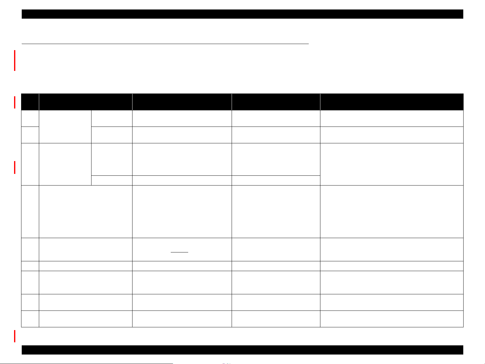
1.1.1 Comparison with Stylus Pro 4000
Table 1-1. Comparative Table
No. Comparative Point
1 Difference between
Hardware The 4-color model is not equipped with
8-color model and
4-color model
2 Printer driver Differs between the 8-color model and
3 Ink set
8-color model
configuration
4-color model MK,C,M,Y
4 Calibration function Colorimetric Calibration:
5 PG setting 5 levels:
6 Harness connection for CR Motor Connected by connectors Connected by soldering Harnesses are made easier to connect/disconnect.
7 Connection between Printhead and
Main Board
8 Material for roll paper guide roller Rubber (elastomer) Plastic (POM) Reduce roller marks traced when roll paper passes
9 Cooling fan Added a cooling fan --- Cools the MAIN Board and the Power Supply Board, and
Note *: PK=Photo Black, MK=Matte Black, LK=Light Black, LLK=Light Light Black, C=Cyan, M=Magenta, LC=Light Cyan, LM=Light Magenta, Y=Yellow, VM=Vivid Magenta,
VLM=Vivid Light Magenta
Stylus Pro 4400/4450/4800
/4880/4880C
an ink holder on the right side.
the 4-color model.
Stylus Pro 4800
K (PK/MK),C,M,Y,LK,LC,LM,LLK
Stylus Pro 4880/4880C
K (PK/MK),C,VM,Y,LK,LC,VLM,LLK
*
*
*
Corrects the amount of dot generation
based on the individual difference
between the following parts:
Printhead
MAIN Board
Power Supply Board
0.7mm/1.2mm/1.5mm
/2.2mm/2.6mm
Added a relay board between
“Printhead, Harness”and the MAIN
Board.
Stylus Pro 4000 Remark
Common ---
Common ---
MK,C,M,Y,PK,LC,LM,LK
MK,C,M,Y
*
Head ID:
Corrects the amount of dot
*
---
Calibration accuracy is improved by taking electrical
variable factor into consideration.
generation based on the individual
difference between the following
part:
Printhead
4 levels:
0.7mm/1.2mm/2.2mm/2.6mm
Added 1.5 mm of PG setting to prevent thin paper from
being damaged. (Lock bush design is changed according
to the added PG setting.)
The Printhead is connected to the
MAIN Board by “Head, Harness”
only.
An additional relay board prevents head drive waveform
being deteriorated when transmitting data form the MAIN
Board to the Printhead.
through the roller.
ventilates the board container.
Product Description Product Description 10

EPSON Stylus Pro 4400/4450/4800/4880/4880C Revision C
1.1.2 Features
Large Format
Max. paper width: 431.8 mm (17"), A2+ size supported
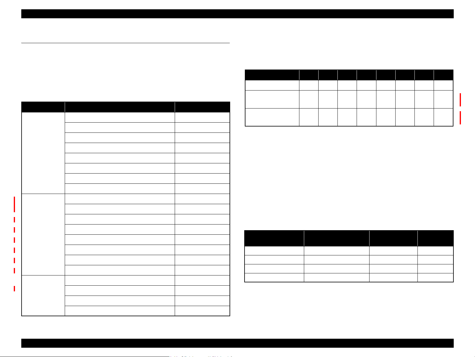
High-Speed Throughput
Stylus Pro 4400/4800
Table 1-2. Throughput (Stylus Pro 4400/4800)
Ink
EPSON
type
8-color Plain
4-color Plain
media
Paper
Matte
Paper
Glossy
Photo
Paper
Paper
Matte
Paper
Glossy
Photo
Paper
Quality Dot size
Economy VSD1 360 x 360 1.3 min.
Speed VSD1 360 x 360 2.3 min.
Quality VSD2 720 x 36 0 2.7 min.
High Quality VSD3 720 x 720 5.5 min.
Speed VSD1 360 x 720 2.3 min.
Quality VSD2 720 x 72 0 5.5 min.
High Quality VSD3 1440 x 720 7.9 min.
High Quality Super
On
Quality VSD2 720 x 72 0 5.5 min.
High Quality 1440 VSD3 1440 x 720 7.9 min.
High Quality 2880 VSD3_HR 2880 x 1440 14.9 min.
Economy VSD1 360 x 360 0.9 min.
Speed VSD1 360 x 360 1.3 min.
Quality VSD2 720 x 36 0 2.3 min.
High Quality VSD3 720 x 720 3.8 min.
Speed VSD1 360 x 720 3.1 min.
Quality VSD2 720 x 72 0 3.8 min.
High Quality VSD3 1440 x 720 5.4 min.
High Quality Super
On
Quality VSD2 720 x 72 0 5.0 min.
High Quality VSD3 720 x 720 7.5 min.
High Quality Super On
VSD3 1440 x 720 14.2 min.
VSD3 1440 x 720 7.3 min.
VSD3 1440 x 720 10.5 min.
Resolution
(dpi)
Throughput
(A2 printing
time *print only)
Stylus Pro 4450/4880/4880C
Table 1-3. Throughput (Stylus Pro 4450/4880/4880C)
Ink
EPSON
type
8-color Plain
4-color Plain
media
Paper
Matte
Paper
Glossy
Photo
Paper
Paper
Matte
Paper
Glossy
Photo
Paper
Quality Dot size
Economy VSD1 360 x 360 1.5 min.
Speed VSD1 360 x 360 2.4 min.
Quality VSD2 720 x 360 2.8 min.
High Quality VSD3 720 x 720 5.2 min.
Speed VSD1 720 x 360 2.4 min.
Quality VSD2 720 x 720 5.2 min.
High Quality 1440 VSD3 1440 x 720 7.5 min.
High Quality 2880 VSD3_HR 2880 x 1440 14.2 min.
Quality VSD2 720 x 720 5.5 min.
High Quality 1440 VSD3 1440 x 720 7.9 min.
High Quality 2880 VSD3_HR 2880 x 1440 14.9 min.
Economy VSD1 360 x 360 1.2 min.
Speed VSD1 360 x 360 1.5 min.
Quality VSD2 720 x 360 2.4 min.
High Quality VSD2 720 x 720 3.7 min.
Speed VSD1 360 x 720 2.5 min.
POP Print VSD2 720 x 720 2.8 min.
Quality VSD2 720 x 720 3.7 min.
High Quality VSD3 1440 x 720 4.3 min.
High Quality Super
On
POP Print VSD2 720 x 720 3.9 min.
Quality VSD2 720 x 720 5.3 min.
High Quality VSD3 1440 x 720 6.4 min.
High Quality Super On
Resolution
(dpi)
VSD3 1440 x 720 5.1 min.
VSD3 1440 x 720 7.7 min.
Throughput
(A2 printing
time *print only)
Product Description Product Description 11

EPSON Stylus Pro 4400/4450/4800/4880/4880C Revision C
Max Quality
High image quality made by various layers of 8-color ink, 2880 x 1440 dpi*,
and minimum of 3.5 pl.
Note *: Stylus Pro 4800/4880/4880C only. 1440 x 720 dpi for Stylus Pro 4400/4450.
Low Running Cost
Independent for each color and 110ml ink cartridge
Optional ink cartridge with larger capacity of 220ml can be used
Paper Handling
Support various media
Automatic roll paper cutter, manual cutter
Automatic cut sheet loading (ASF)
Rear manual feed/ Front manual feed (thick paper only)
Borderless print for 4 sides
ASF support
Compatibility with Other LFPs
Commands are upper compatible with following models.
Stylus Pro 4400/4800
Stylus Pro 4000/7000/7500/7600/9000/9500/9600/10000/10000CF/
10000 Dye/10600CF/10600UC
Stylus Pro 4450/4880/4880C
Stylus Pro 4000/4400/4800/7000/7400/7500/7600/7800/9000/9400/
9500/9600/9800/10000/10000CF/10000 Dye/1 0600/
10600CF/10600UC
The latest RIP technology
Stylus Rip Professional 3
Others: Various 3rd Party RIP
Product Description Product Description 12
EPSON Stylus Pro 4400/4450/4800/4880/4880C Revision C
1.2 Basic Specifications
1.2.1 Print Specifications
Printing
On-demand ink-jet
Nozzle configuration
Table 1-4. Nozzle configuration
Model Name Ink Nozzles
Stylus Pro 4800 Black(MK or PK) 180
Light Black 180
Light Light Black 180
Cyan 180
Magenta 180
Light Cyan 180
Light Magenta 180
Yellow 180
Stylus Pro 4880
Stylus Pro 4880C
Stylus Pro 4400
Stylus Pro 4450
Black(MK or PK) 180
Light Black 180
Light Light Black 180
Cyan 180
Vivid Magenta 180
Light Cyan 180
Vivid Light Magenta 180
Yellow 180
Matte Black 360
Cyan 360
Magenta 360
Yellow 360
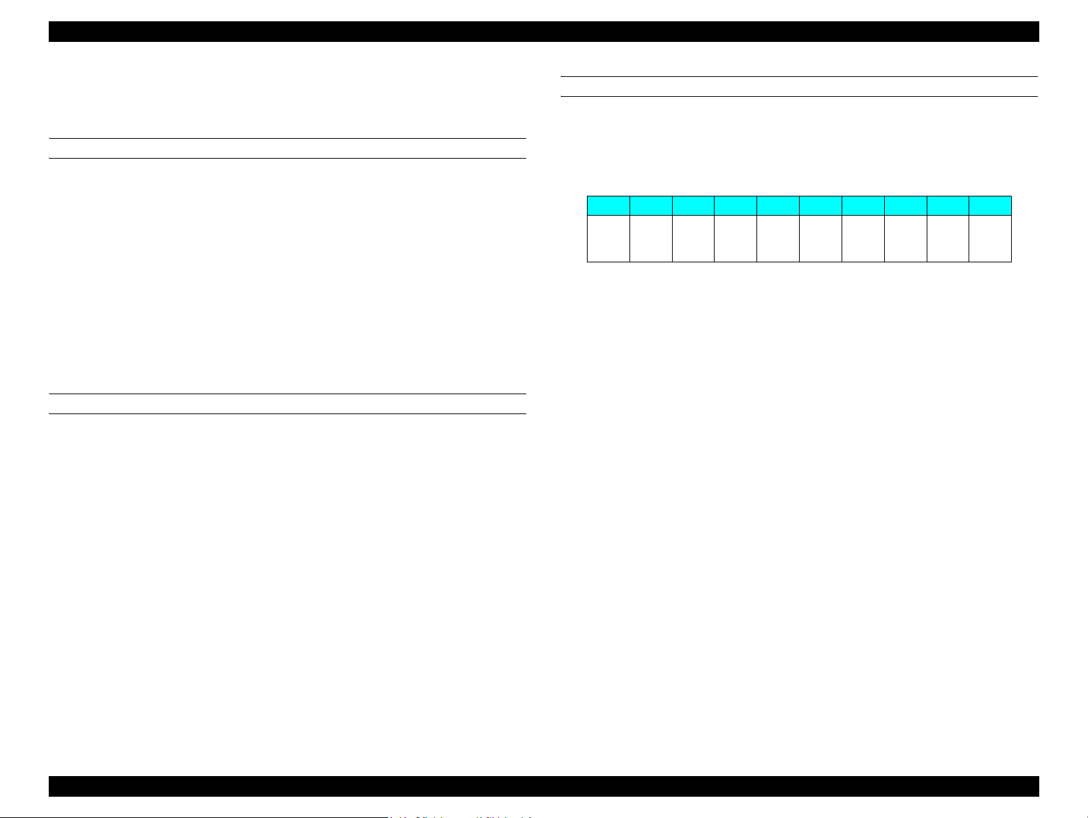
Nozzle pitch
0.141 mm (1/180 inch) for each color
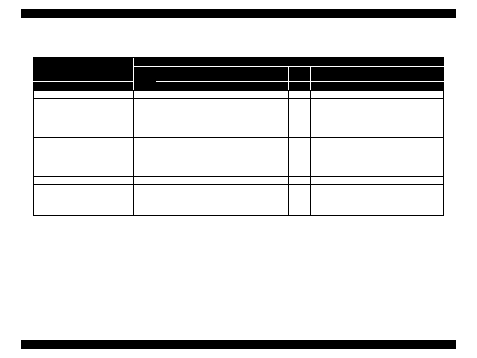
Ink Set Configuration
Table 1-5. Ink Set Configuration
Mode Name 1-row 2-row 3-row 4-row 5-row 6-row 7-row 8-row
*2
Stylus Pro 4800 K
Stylus Pro 4880
Stylus Pro 4880C
Stylus Pro 4400
Stylus Pro 4450
Note *1: Rows below are counted from the front left side of the printer.
*2: Ink change (MK<=>PK) is available to users.
K
MK C M Y - - - -
C M Y LK LC LM LLK
*2
C VM Y LK LC VLM LLK
*1
Printing direction
Bi-direction with logic seeking (high-speed return, high-speed skip only)
Printing speed and printable area
Alphanumeric characters
• Character quality : High quality
• Character pitch : 10 cpi
• Printable area : 167 characters
• Printing speed : 320 cps max.
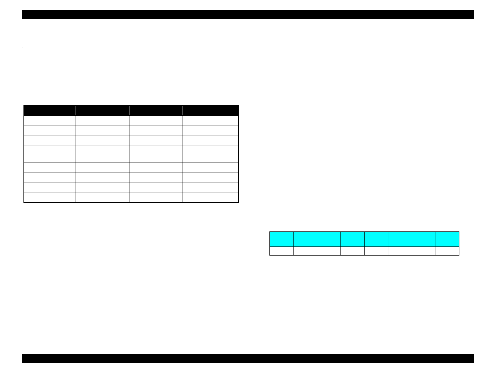
Graphic Mode
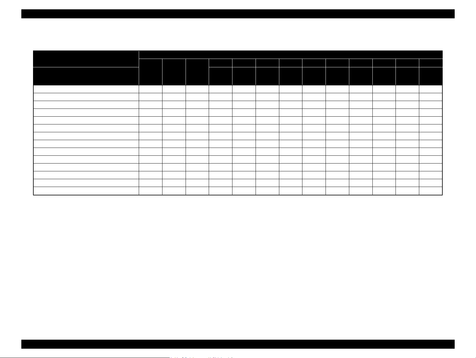
Table 1-6. Graphics Modes
Horizontal resolution
(dpi)
360 439.8 mm (17.31") 6,233 320 cps
720 439.8 mm (17.31") 12,466 240 cps
1440 439.8 mm (17.31") 24,933 240 cps
2880 439.8 mm (17.31") 49,867 240 cps
Note 1: Includes left margin of 5 mm (Maximum), right margin of 3 mm.
2: Standard maximum printable area in normal mode is 425.8 mm (16.7 inch)
Maximum printable area
Maximum number
of printable dots
Printing
speed
Product Description Basic Specifications 13

EPSON Stylus Pro 4400/4450/4800/4880/4880C Revision C
1.2.2 Character Specification
Character tables
PC 437 (Alphanumeric characters extension graphics)
Font
EPSON original font – Alphanumeric character Courier
1.2.3 Control Code
Control code
ESC/P Raster
1.2.4 Paper Feed Specification
Paper fee d i ng
Friction feed
Line spacing
1/6 inch or programmable at 1440 inch
Note: Paper feed resolution is 0.002936758 mm.
Paper pa th
Roll paper
Manual (front/back)
Automatic sheet feeder
Feed speed
6.35 mm paper feed: 215 ± 10 msec
(except front rush, back rush, and hold time)
1.2.5 Paper Feeder Specification
ASF
Feeds paper automatically by Automatic Sheet Feeder.
Rear Manual Feed
Loads automatically from rear manual feed opening.
Front Manual Feed
Loads automatically from front manual feed opening.
Roll Paper Feed
Sets spindle to rear roll-paper holder.
Product Description Basic Specifications 14
EPSON Stylus Pro 4400/4450/4800/4880/4880C Revision C
1.2.6 Paper Specification
1.2.6.1 Roll Paper
CONTAINABLE PAPER
The printer accepts following plain paper and EPSON special paper. It is not
assured feeding and print quality with any other paper except them.
Paper Size
2" core : 203 ~ 432 mm (W) x ~ 45 m (H) (within roll size)
3" core : 203 ~ 432 mm (W) x ~ 202 m (H) (within roll size)
Roll Size
2" core : Under 103 mm ext. diameter for 1 roll setting
3" core : Under 150 mm ext. diameter for 1 roll setting
Thickness : 0.08 mm ~ 0.50 mm
PLAIN PAPER
It is assured feeding only with following specifications.
Paper Size
2" core : 203 ~ 432 mm (W) x ~ 45m (H) (within roll size)
3" core : 203 ~ 432 mm (W) x ~ 202m (H) (within roll size)
Roll Size
2" core : Under 103 mm ext. diameter for 1 roll setting
3" core : Under 150 mm ext. diameter for 1 roll setting
Thickness : 0.08 ~ 0.15 mm
Weight : 64 ~ 130 gf/m
Type : Plain paper, Recycle paper
2
BORDERLESS PRINT WIDTH
Borderless print for right and left is assured with following paper width roll
paper.
Borderless Print Width
Table 1-7. Borderless Print Width
8" 8.25" 8.5" 10" 12" 13" 14" 16" 16.5” 17”
203.2mm210mm
(A4)
(LTR)
216mm
257mm
(A3)
297mm
300mm
(A3+)
329mm
355.6
mm
400mm
(A2)
420mm
431.8
mm
But following types are not recommended for borderless printing.
Single Weight Matte Paper
Enhanced Matte Paper
Textured Fine Art Paper
Ultra Smooth Fine Art Paper
NOTE 1: Paper should have no wrinkles or tears, and the surface should be
smooth.
2: The force to remove the end of the roll paper from the core at the
beginning of rolling paper should be between 300gf and 2000gf.
3: If 3" core is used, a product-exclusive option (roll paper spindle 3")
is necessary.
4: It is used under normal condition (temperature 15°C ~ 25°C,
humidity 40% ~ 60%RH).
5: Roll paper can be printed before paper comes out of the core.
(Reference: Remaining paper length is 300mm approx. when roll
paper come out of the core.)
6: Mechanism clips print data out of over-printable area for
borderless print.
7: For A2 size, spacer is specially needed.
Product Description Basic Specifications 15
EPSON Stylus Pro 4400/4450/4800/4880/4880C Revision C
1.2.6.2 Cut Sheet
CONTAINABLE PAPER
The printer accepts following plain paper and special paper. It is not assure d
feeding and print quality with any other paper except plain paper and special
paper.
Paper Size
Table 1-8. Cut Sheet Size (Containable Paper)
Paper Size Size (H x W) Paper Size Size (H x W)
B3 364 mm x 515 mm US-C Size 17 x 22 inch
B4 257 mm x 364 mm 16 x 20 inch 16 x 20 inch
A2 420 mm x 594 mm 300 mm x 450 mm 300 mm x 450 mm
Super A3/B
(A3 +)
A3 297 mm x 420 mm 11 x 14 inch 11 x 14 inch
A4 210 mm x 297 mm Quarter 10 x 12 inch
Thickness
0.08 ~ 1.50 mm (paper length; 279 mm ~ 610 mm)
NOTE 1: Paper should have no wrinkles, tears, or stains an d
329 mm x 483 mm US-B Size
(Ledger)
Letter 8.5 x 11 inch
8 x 10 inch 8 x 10 inch
11 x 17 inch
the surface should be smooth.
2: Paper should be placed with its fibrous direction same
as the feed direction. (Basically portrait orientation)
3: 0.08 ~ 1.50mm paper thicknesses are supported for
long-edge insertion.
4: A4, letter, or 8 x 10 inch papers should not be placed
in landscape orientation on rear manual feed path.
5: Auto nozzle check is not available for 8 x 10 inch or
smaller paper.
6: Front manual feed is not available for soft paper or
0.2mm or less thickness paper.
PLAIN PAPER
It is assured feeding only with following specifications.
Paper Size : Identical to Table 1-8 "Cut Sheet Size (Containable
Paper)"(p16).
Thickn ess : 0.08 ~ 0.11 mm
Weight : 64 ~ 130 gf/m
2
Type : Plain paper, Recycle paper
NOTE 1: Paper should be placed in portrait orientation.
2: Paper should have no wrinkles, tears, or stains and the surface
should be smooth.
3: It is used under normal condition (temperature 15ºC ~ 25ºC,
humidity 40% ~ 60%RH).
BORDERLESS PRINT WIDTH
Borderless print for right and left is assured with following paper width. But
following types are not recommended for borderless printing.
NOTE: 300 mm, 400 mm are supported for Europe.
Borderless Print Width
Table 1-9. Borderless Print Width
8.25””
210mm
A4 LTR B4 A3 A3+ – 16"
NOTE 1: Mechanism clips print data out of over-printable area for
2: Borderless printing is not available for A2 cut sheet.
8.5"
216mm
10"
257mm
borderless print.
12"
297mm
13"
329mm
14"
355.6mm
16"
400mm
431.8mm
x20" US-C
17"
Product Description Basic Specifications 16
EPSON Stylus Pro 4400/4450/4800/4880/4880C Revision C
1.2.6.3 Special Paper
Cut Sheet
Table 1-10. Availability with Cut Sheet
Media Size
Cut Sheet
PG
Name 203x279 210x297 216x279 229x305 254x364 279x356 297x420 279x432 305x457 329x483 400x600 420x594 432x559
Premium Ink Jet Plain Paper (Xerox 4024) 1.5 – @ @ @ @ – @ @ @ – – @ @
Premium Ink Jet Plain Paper (Genuine) 1.5 – @ –––––––––––
Bright White Inkjet Paper 1.5 – @ –––––––––––
EPSON Photo Quality Inkjet Paper 1.5 – §§–––§––§–––
EPSON Enhanced (Archival) Matte Paper1.2–§§–––§––§––§
Watercolor Paper-Radiant White 1.2 – ––––––––§–––
EPSON Premium Glossy Photo Paper 0.7 – §§–––§––§–––
EPSON Premium Semigloss Photo Paper0.7–§§–––§––§–––
Premium Semimatte/Luster Photo Paper<250>
Premium Luster Photo Paper 0.7––§––––––§–––
P;atinum Photo Paper 0.7 – §––––§––§–––
EPSON Velvet Fine Art 1.2––§––––––§–––
Single Weight Matte Paper 1.5 – ––––––––§–§§
Ultra Smooth Fine Art Paper 1.5 – ––––––––§––§
Proofing Paper Semimatte 0.7 – ––––––––§–––
Velvet Fine Art Paper – –§––––––§–––
(mm)
8"x10" A4
1.2––––––––––––§
US-A
LTR
Arch.A
9x12"
B4 11"x14" A3 US-B
Arch.B
12x18"
Super
A3/B
400x600 A2 US-C
Note 1: Symbol ~: Assured, @: Assured for plain paper only
2: Assured range for image quality 15°C 40%RH ~ 25°C 60%RH
3: PG setting value of Velvet Fine Art Paper is accordance with the panel setting.
Product Description Basic Specifications 17
EPSON Stylus Pro 4400/4450/4800/4880/4880C Revision C
Roll Paper
Table 1-11. Availability with Roll Sheet
Roll Paper
Core"
Name
Bright White Inkjet Paper 2 1.5 A § – ––––––§–
Single Weight Matte Paper Roll 2 1.2 A – – ––––––§§
Enhanced Matte Paper Roll 3 1.2 A – – –––––––§
Photo Glossy Paper Roll 2 0.7 A – – ––––––§–
Photo Semigloss Paper Roll 2 0.7 A – – ––––––§–
Premium Glossy Photo Paper<250>Roll 3 0.7 A – – –––––§––
Premium Semigloss Photo Paper<250>Roll 3 0.7 A – – –––––§––
Premium Semimatte Photo Paper <250 >Roll 3 0.7 A – – –––––§––
Premium Luster Photo Paper <250 >Roll 3 0.7 A – § §––––§––
Ultra Smooth Fine Art Paper 3 1.5 A – – –––––––§
Textured Fine Art Paper 3 1.2 A – – –––––––§
Proofing Paper Semimatte Roll 2 0.7 A – – ––§––––§
Photo Paper Gloss 250 3 0.7 A – – –––––––§
Tracing Paper 2/3 1.2 A – – ––§–––
SpindlePG(mm)
Cutter
Auto
or
Manual
A4 10" 30cm 12" A3+ 14" 40cm 16" A2 17"
210 254 300 305 329 356 400 406 420 431.6
Media Size
@
–
Note 1: Symbol ~: Assured, @: Assured for plain paper only
2: Assured range for image quality 15°C 40%RH ~ 25°C 60%RH
Product Description Basic Specifications 18
EPSON Stylus Pro 4400/4450/4800/4880/4880C Revision C
1.2.7 Mechanism Specifications
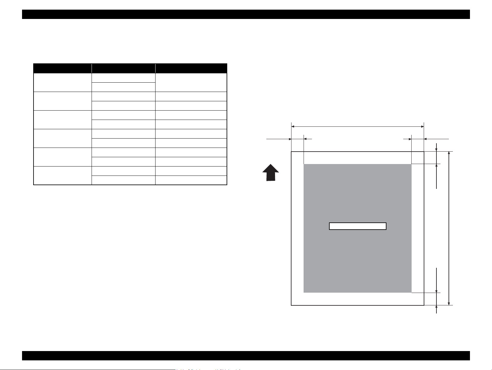
1.2.7.1 Printable Area
Table 1-12. Printable Area
Item Roll paper / Cut Sheet Dimension
PW (Paper width)
PL (Paper length)
TM (Top margin)
BM (Bottom margin)
LM (Left margin)
RM (Right margin)
Note *: Max. value is roll paper 439.8mm(17.31"), and cut sheet 437.8mm (17.24") for
no margin print.
Roll paper
Cut Sheet
Roll paper Max. 202m
Cut Sheet 279mm~594mm
Roll paper 0mm/3mm/15mm/35mm
Cut Sheet 0mm/3mm
Roll paper 0mm/3mm/15mm(/35mm)
Cut Sheet 0mm/3mm/14mm
Roll paper 0mm/3mm/15mm
Cut Sheet 0mm/3mm
Roll paper 0mm/3mm/15mm
Cut Sheet 0mm/3mm
203mm~431.8mm (17")
The printer detects paper width when paper is set (print data is accepted
for ASF). (If set paper width detection is OFF, it doesn't detect paper
width.)
It doesn't print the image beyond printable area specified with paper size
setting or detected paper width. (It may print on the platen if set paper
width detection is OFF.)
Margins of roll paper can be changed with the panel as following;
Top/bottom 15mm, left/right 3mm
Top/bottom 25mm, left/right 3mm
Top/bottom/left/right 3mm
Top/bottom/left/right 15mm
NOTE 1: Under special condition, it is possible to set right and
left margin (LM, RM) to 0.
2: When special internal pattern is printed on roll paper,
right and left side margin are fixed to 3mm. “1.4.4.8
Roll Paper Margin (p.52)” for details.
*
For borderless print, right and left surplus printable area is maximum 3mm
on the home position side and maximum 5mm on the other side distance
from paper edge to platen (sponge width) is less th an 3m m, the m axim u m
surplus print quantity not on platen (0mm~3mm) is printable area.
Conditions for separating into multiple pages for printing cut sheet.
1. For thick paper, print until the bottom edge reaches to 14mm.
Remaining data is invalid and not to be printed.
2. When error occurred such as releasin g paper lever when prin ting, then
print is separated to next page after down margin is printed.
When printing on cut sheet at resolution of 2800 x 1440dpi and setting the
bottom margin to 3mm, the actual bottom margin will be 3.8mm.
PW
LM RM
TM
Printable Area
Paper Feed Direction
Figure 1-1. Printable Area
PL
BM
Product Description Basic Specifications 19
EPSON Stylus Pro 4400/4450/4800/4880/4880C Revision C
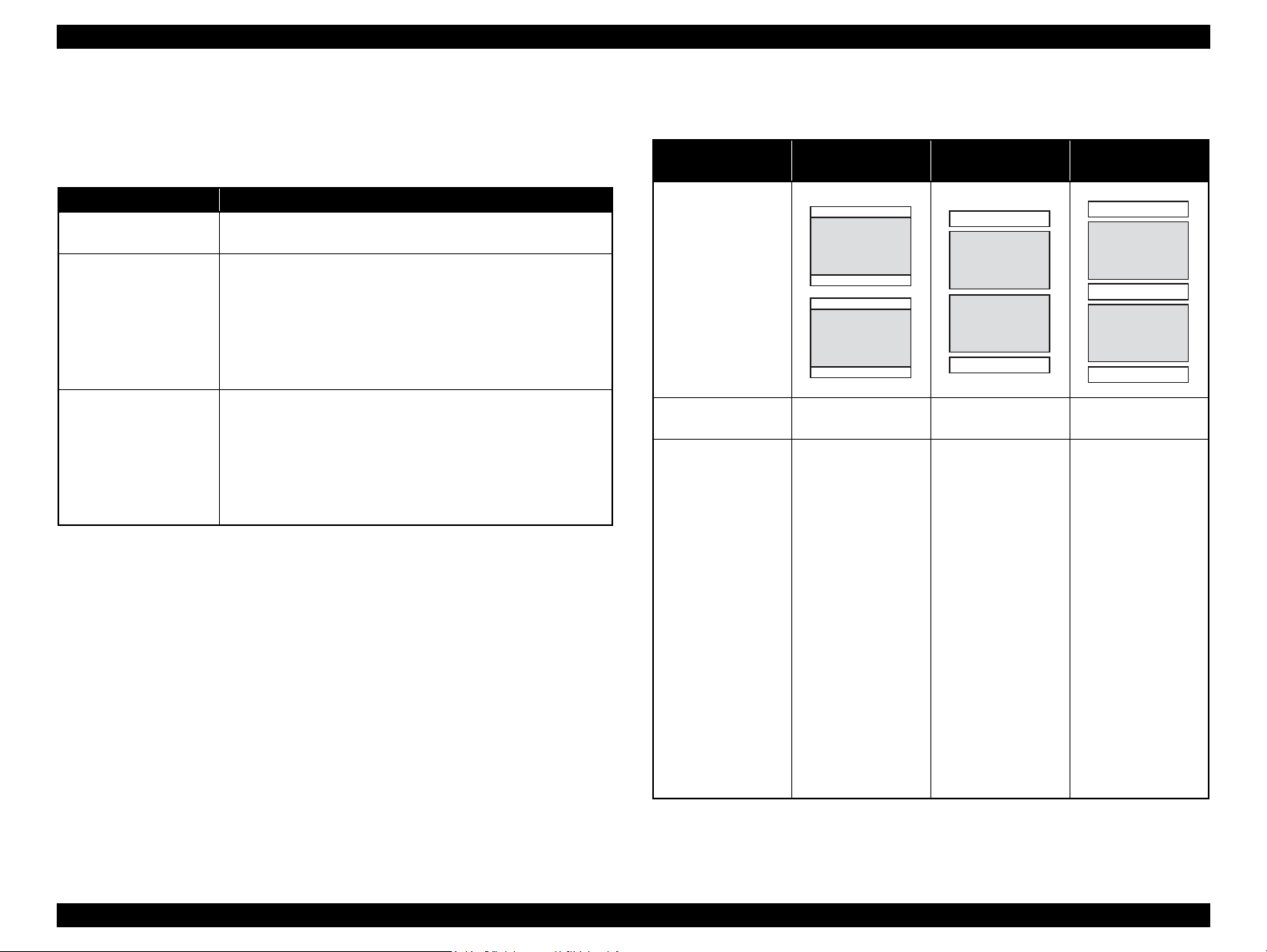
1.2.7.2 Borderless Print Specification
By driver's command transmission, supports the following borderless print
mode. Supports the following 3 modes.
Table 1-13. Borderless Print Specification mode
Mode Operation
Right and left
borderless (default)
4 sides borderless/1 cut You can set 4 sides margins to zero. Use the following
4 sides borderless/2 cut You can set 4 sides margins to zero. Use the following
Note 1: For 4 sides borderless, after cutting, up and down size of the printing will be
smaller by approximately 2mm than the actual printing size.
2: When the roll paper cutter is OFF and page line printing is ON, print the page
line at each cutting position including front edge page.
3: In following media, if 1 cut is selected at borderless printing, it is cut as 2 cut to
prevent scraping top of paper.
• Premium Glossy Photo Paper
• Premium Semigloss Photo Paper
Note *: Recommended a borderless length for glossy paper is 60mm, for other paper
is 100mm.
You can set only the right and left margins to zero. At this time,
up and down margins are set by roll paper margin setting.
method for cutting.
Starting of JOB, take minimum cut length for margin and
cut while printing.
While JOB, new page has no margin, cut at image border
position in continuing print.
End of JOB, cut at the bottom of the image.
method for cutting.
At the front edge page, take refresh margin length for
margin, cut while printing.
At the end of the page, cut at the bottom of the image.
To discard the remaining part of printing after cut, cut the
paper after advancing the paper to minimum cut length.
*
Borderless setting method
Table 1-14. Borderless setting
Borderless mode
Right and left
borderless
Printer operation
Driver setting Borderless print Borderless print
Note Default setting
4 sides borderless
(1 cut)
Single cut
The upper edge
cut is performed
by interrupting
print operation;
there is chance of
color shading
according to data.
By adjusting
cutter position,
there is chance of
data from
continuous page
remaining in top
or bottom edge of
the page.
4 sides borderless
(2 cut)
Borderless print
Double cut
The upper edge
cut is performed
by interrupting
print operation;
there is chance of
color shading
according to data.
To avoid
remaining of
margin, cut off the
top and bottom
part of the paper
by going inside of
image.
Therefore the
actual size will be
about 2mm
smaller than the
specified print
area.
Product Description Basic Specifications 20
EPSON Stylus Pro 4400/4450/4800/4880/4880C Revision C
Borderless Print Assurance Conditions
Borderless print is assured under the following conditions.
Temperature condition: 15 to 25 degrees C, 40 to 60%
Media Type: Photo media
POP/Poster media
Note 1: Refer to “1.2.6 Paper Specification (p.1 5)” for details on assured media for
borderless print.
2: Borderless printing is not assured if the surface of few rolls is extended due to
moisture absorbent.
3: Medea types and sizes other than above assure borderless margins equal to or
more than PX-10000 / PX-9000. However, margins may appear on the right and
left edges, if paper wrinkled due to conditions such as temperature is used.
*1,*2
Right and Left Surplus Printable Area
For right and left surplus printable area
available:
Left (opposite side of home position) = 1.5mm/ right (home position side) =
1.5mm
Left (opposite side of home position) = 3.0mm/ right (home position side) =
3.0mm
Left (opposite side of home position) = 5.0mm/ right (home position side) =
3.0mm
Note *1: Right and left surplus printable area can be selected on the driver.
*2
*2: When the media is wrinkled, a selection of "Left (oppo site side of home
position) = 5.0mm/ right (home position side) = 3.0mm" is recommended to
prevent margins from appearing on the right and left edges.
*1
, the following settings are
1.2.7.3 Paper Set Lever
Table 1-15. Paper Set Lever
Lever Position Description
Backward Position for paper setting
(Paper holding is released, and paper can be set.)
Forward Ready-to-print position
(Paper is fixed, and it becomes ready to be printed.)
1.2.7.4 Cut Specification
There are two types, auto cut and manual cut for roll paper cutting.
C A U T I O N
AUTOMATIC CUT FOR ROLL PAPER
For paper that automatic cut is admitted, cut the paper using the following
method by setting panel setting to "roll paper automatic cut".
Mechanic condition
Distance between the cutting position and paper setting position
Distance between the cutting position and cutter mark
Minimum cut length
Initial cut
(Pressing the lever down when there is
paper and pushing the [Paper Source/
Paper Cut (<)] key for 3 sec.)
Cut when driver ends print. Cutting method (include Star Wheel
Initial cut when printing Cut while printing is prohibited in this
Initial cut in an original standby situation Deliver size of L1 paper and cut by 2-step
After printing in automatic cut OFF mode,
start initial cut in automatic cut ON mode.
Cut when paper width detection is OFF. Same as paper width detection is ON.
Note *: User need to remove the strip of paper that remains between eject roller and
Making cutting action to paper wh ich au to ma ti c cu tt in g is
prohibited will cause damage to the printhead.
L0=205.43mm
L1=27.6 mm
L2=130 mm (default value)
Table 1-16. Cutting Conditions and Cutting Methods
Cut condition Cutting method
Deliver size of L1 paper and cut by 2-step with
roll paper holding Star Wheel. (100cps)
holding), cutting pressure, minimum cut
length follows to the media table.
model. (Product specification)
with roll paper holding Star Wheel. (100cps)
Cut by 2-step with roll paper holding Star
Wheel reserving size of L2. (100cps)
(Paper jam is not occurred for 2-step cut.)
nip roller when executing this operation without L2 reservation.
*
Product Description Basic Specifications 21

EPSON Stylus Pro 4400/4450/4800/4880/4880C Revision C
MANUAL CUT FOR ROLL PAPER
When using paper for which automatic cutting is prohibited, use manual cut
with the steps below.
1. Use [Paper Source / Paper Cut] button to select Roll Paper Auto Cut OFF
(" ").
2. Press and hold the [Paper Source / Paper Cut] button for 3 seconds.
3. The paper will be automatically fed to the manual cut position and the
printer will go offline, indicating “Pause”on the panel.
4. Cut off paper using own scissors.
5. Then press the [Pause] button and the paper will be fed back, and the
printer will be online.
NOTE 1: Auto cutter supports all genuine roll paper.
2: Paper of 3rd party media and generally auto cutter is prohibited.
• Fiber-form paper such as cloth.
• Rigidity is extremely high paper such as Vinyl (Outdoor type) or
Fine Art type.
1.2.8 Electrical Specification
Rated voltage: AC 100 ~ 240V
Input voltage range: AC 90 ~ 264V
Rated frequency range: 50 ~ 60Hz
Input frequency range: 49 ~ 61Hz
Rated current: 100-240V ac, 50-60Hz, and 1.0-0.5A
Power consumption
operation status
• Stylus Pro 4400/4800: Less than 59 W
• Stylus Pro 4450/4880/4880C: Less than 55 W
Less than 5 W for low power status (Shifting time: 15 minutes)
Less than 1 W for Power OFF
Insulation resistance: More than 10M ohms
(Between AC line and chassis is DC 500V)
Dielectric strength: AC 1.0kV rms 1min. or AC1.2kV rms 1 sec.
(Between AC line and chassis)
Leakage: Less than 0.25mA
[Adapts Japan National Electronics Development
Incorporated Association "Personal Computer
Industry Standard" (PC-11-1988)]
Adapted standard regulation
Adapts International Star Program
(Adapts category: measure for harmonic
component suppression guideline)
Adapts VCCI class B
Product Description Basic Specifications 22
EPSON Stylus Pro 4400/4450/4800/4880/4880C Revision C
1.2.9 Reliability
PRINTER LIFE
Approx. 20,000 pages (A2, plain paper, quality, 720 x 360 FOL, Bi-D)
AVERAGE CUTTER LIFE
Coated paper: Approx. 2,000 cut
Film: Approx. 1,000 cut
REPLACEMENT PARTS LIFE
Maintenance Unit: Approx. 20,000 sheets
(A2, plain paper, speed mode, continuous printing)
The maintenance unit reaches its end of life when
the number of the pump rotation exceeds 160,000
times.
1.2.10 Environmental Conditions
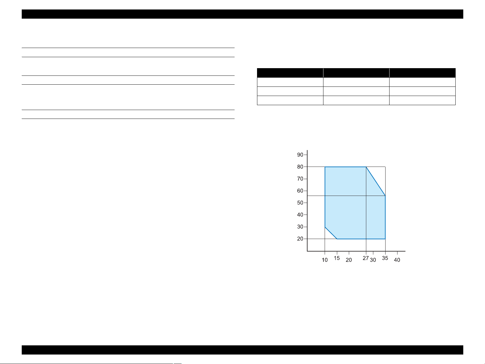
1.2.10.1 Temperature/Humidity
Table 1-17. Temperature/Humidity
Condition Temperature
During operation 10 ~ 35°C 20 ~ 80%
During storage -20
During transport -20
Note *1: Within one month for 40ºC, within 120 hours for 60ºC
*2: No condensation. These values are applicable only within the range as shown
below. Print quality is assured only within a temperature of 15 to 25 degrees C
and a humidity of 40 to 60%.
Humidity (%)
~ 40°C 20 ~ 85%
~ 60°C 5 ~ 85%
*1
Humidity
*2
Temperature (°C)
Figure 1-2. Environmental Conditions: Temperature/Humidity
Product Description Basic Specifications 23
EPSON Stylus Pro 4400/4450/4800/4880/4880C Revision C
1.2.10.2 Vibration
During op e ratio n: 0.15G, 10-55Hz X, Y, Z direc tio ns
During storage: 0.50G, 10-55Hz X, Y, Z directions
1.2.10.3 Shock
During op e ratio n: 1G, 1ms max. X, Y, Z directions
During storage: 2G, 2ms max. X, Y, Z directions
NOTE 1: Check that the printhead is capped during storage.
2: Check that the printhead is capped, then remove ink cartridges
from the body, and make sure ink cartridge cover is closed during
transport.
3: If the printer head uncapped, and the ink cartridge is attached,
switch the power ON. Switch the power OFF when capping is
completed.
4: Left out in condition of temperature under -15°C; the ink in the
printhead and ink cartridge freezes. It takes about 3 hours for the
frozen ink to be usable under the condition of 25°C.
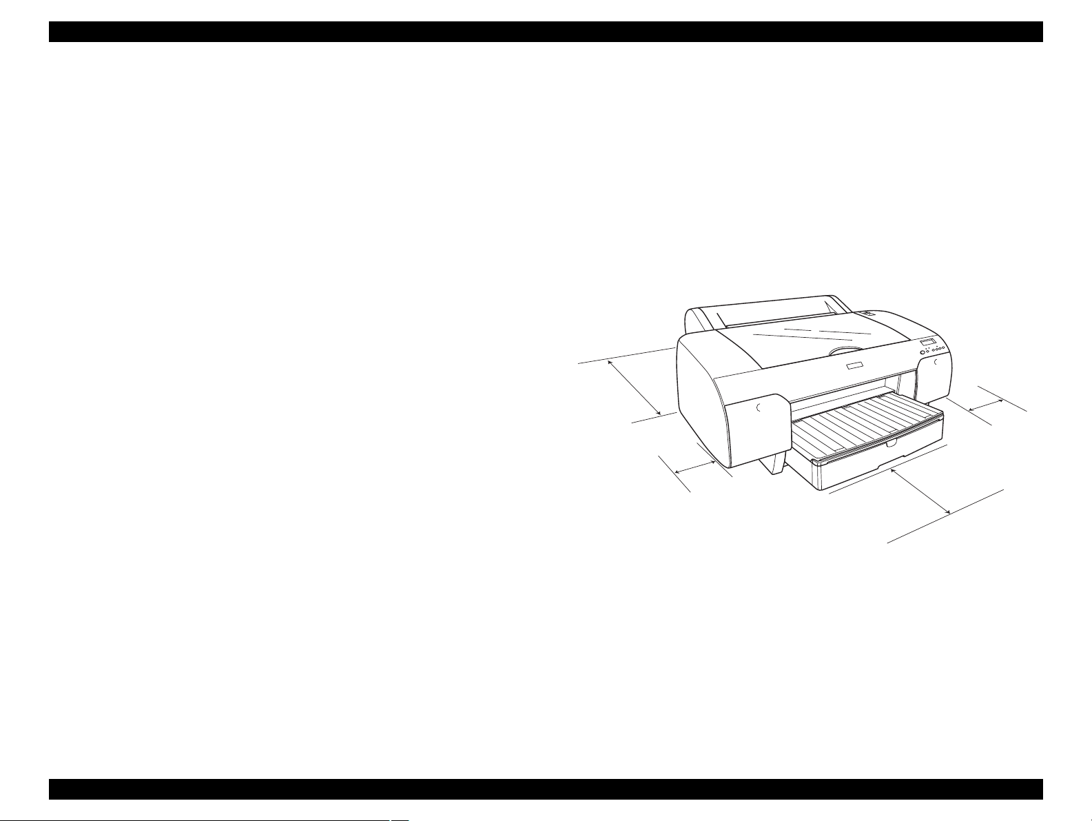
1.2.10.4 Surrounding Space
Provide the printer with an enough surrounding space to ensu re proper
installation of accessories and replacement of consumables and easy wo rk for
daily maintenance.
From the front of the printer: 35cm or more
(When the paper tray is extended.)
From the rear of the printer: 40cm or more
(When cut sheets are set by hand
insertion from the front.)
From the both sides of the printer: 15cm or more
40cm or
more
15cm or
more
35cm or more
15cm or
more
Figure 1-3. Surrounding Space
Product Description Basic Specifications 24
EPSON Stylus Pro 4400/4450/4800/4880/4880C Revision C
1.2.11 Quality Standards for Completed Products
NOISE
Sound pr essure level: Less than 50 dB
(4 direction average, compliant with ISO9296)
*Should be no impact, abnormal or harsh noise.
INITIALIZING TIME AT POWER ON
Within 1 minu te (* exclud in g waiting time such as Timer CL)
TIME FOR INITIAL INK CHARGE
Less than 8 minutes
(* until initial ink charge is finished after the ink lever is lowered)
MTBF (MEAN TIME BETWEEN FAILURES)
20,000 hours with power on (except when electronic parts and fans have
any malfunction)
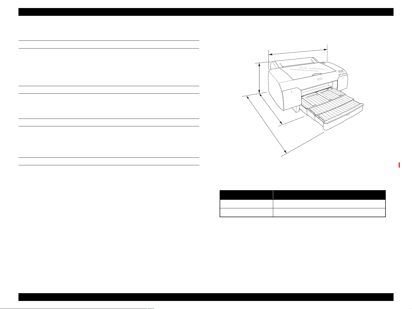
1.2.12 Overall Dimensions
848
354
764
1099
Figure 1-4. Overall Dimensions of Stylus Pro 4400/4450/4800/4880/4880C
Dimensions of Unit
Condition Width (W) x Depth (D) x Height (H) (mm)
When tray is stored 848 x 764 x 354
When tray is extended 848 x 1099 x 354
Weight
8-color model: Approx. 40.2kg (ink cartridge and paper is not included)
4-color model: Approx. 39.0kg (ink cartridge and paper is not included)
Product Description Basic Specifications 25

EPSON Stylus Pro 4400/4450/4800/4880/4880C Revision C
1.2.13 Accessories
Stylus Stylus Pro 4400/4450/4800/4880/4880C accessories and options are
shown below.
Standard Accessories
Manual set
Software CD-ROM
• Printer Driver
• EPSON LFP Remote Panel
AC Cable
Spacer for borderless printing 8”/A2 roll paper
17 (2"/3") inch normal tension spindle (With 2 adapters for exclusive
paper core use)
Ink cartridges 110ml 1 each
8-color model
• Stylus Pro 4800: PK,C,M,Y,LC,LM,LK,LLK
• Stylus Pro 4880/4880C: PK,C,VM,Y,LC,VLM,LK,LLK
4-color model
• Stylus Pro 4400/4450: MK,C,M,Y
Maintenance Tank
Guarantee Card
Card holder
Individual Packaging
Special Options
Maintenance Tank (C12C890191)
Special Consumables
Ink cartridge (8-color)
• Stylus Pro 4800
Table 1-18. Ink Cartridge (Stylus Pro 4800)
Model Number
Ink cartridge
110 ml 220 ml
Photo Black C13T564100 C13T565100
Matte Black C13T543800 C13T544800
Cyan C13T564200 C13T565200
Magenta C13T564300 C13T565300
Yellow C13T564400 C13T565400
Light Cyan C13T564500 C13T565500
Light Magenta C13T564600 C13T565600
Light Black C13T564700 C13T565700
Light Light Black C13T564900 C13T565900
• Stylus Pro 4880/4880C
Table 1-19. Ink Cartridge (Stylus Pro 4880/4880C)
Model Number
Ink cartridge
110 ml 220 ml
Photo Black C13T605100 C13T606100
Matte Black C13T613800 C13T614800
Cyan C13T605200 C13T606200
Vivid Magenta C13T605300 C13T606300
Yellow C13T605400 C13T606400
Light Cyan C13T605500 C13T606500
Vivid Light Magenta C13T605600 C13T606600
Light Black C13T605700 C13T606700
Light Light Black C13T605900 C13T606900
Product Description Basic Specifications 26

EPSON Stylus Pro 4400/4450/4800/4880/4880C Revision C
Ink cartridge (4-color model)
• Stylus Pro 4400
Table 1-20. Ink Cartridge (Stylus Pro 4400)
Model Number
Ink cartridge
110 ml 220 ml
Matte Black C13T543800 C13T544800
Cyan C13T543200 C13T544200
Magenta C13T543300 C13T544300
Yellow C13T543400 C13T544400
• Stylus Pro 4450
Table 1-21. Ink Cartridge (Stylus Pro 4450)
Model Number
Ink cartridge
110 ml 220 ml
Matte Black C13T613800 C13T614800
Cyan C13T613200 C13T614200
Magenta C13T613300 C13T614300
Yellow C13T613400 C13T614400
Options Common to Other Printers
2/3 inch Dual Roll Feed Spindle (C12C811171)
2/3 inch Dual Roll Feed Spindle (High Tension) (C12C811191)
Roll Paper Belt (C12C890121)
EpsonNet 10/100 BASE RX High Speed Int. Print Server
(C12C824052*) (Stylus Pro 4400/4800 only)
Borderless Print Spacer for 420 mm and 8 inch Roll Paper
(C12C811201)
Auto Cutter Spare Blade (C12C815291)
Note *: The asterisk (*) is a substitute for the last digit of the product code, which
varies by location.
Special paper (Refer to "1.2.6 Paper Specification (p.15)" for paper
type and size)
Black ink conversion kit (ICCVK36)
Product Description Basic Specifications 27
EPSON Stylus Pro 4400/4450/4800/4880/4880C Revision C
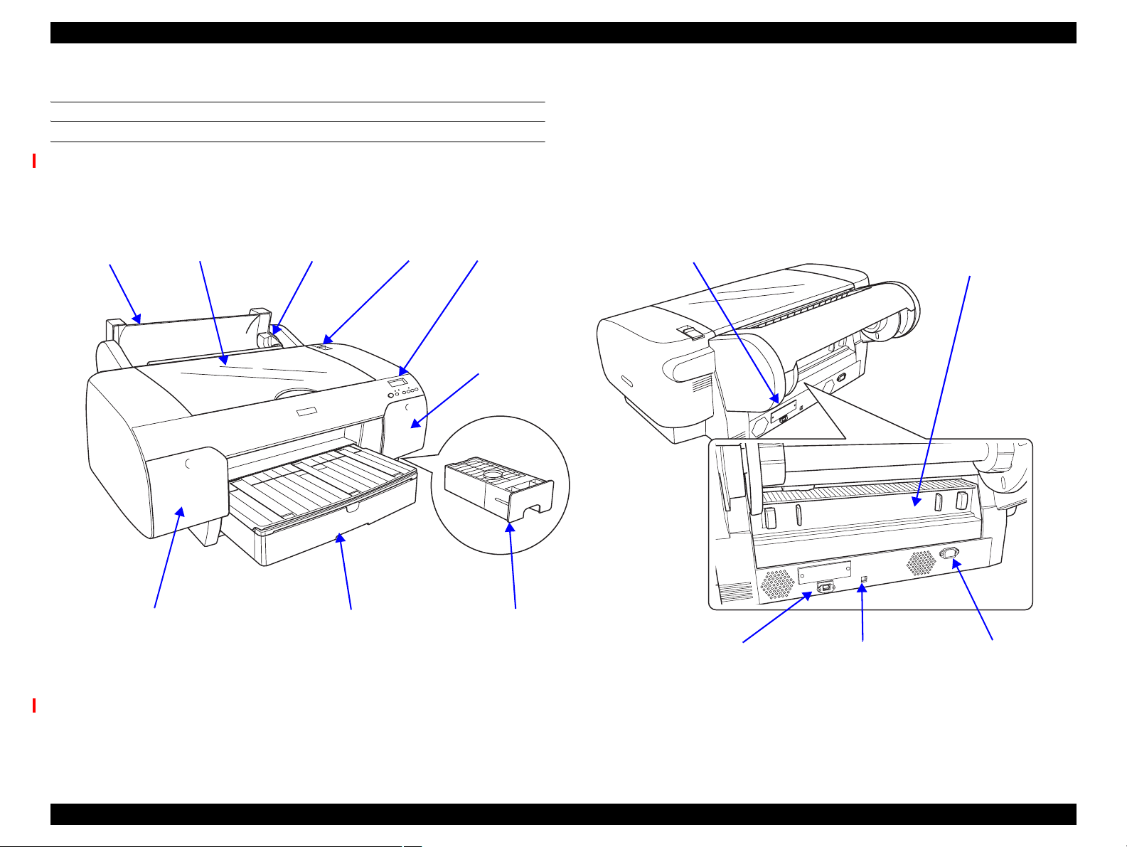
1.3 External View and Parts Names
EXTERNAL VIEW
Stylus Pro 4400/4800
Paper Cover
(Left side)
Printer Cover Spindle Paper Set Lever Control Panel
Ink Cartridge Box
(Right side)
ASF Cassette Maintenance TankInk Cartridge Box
Type-B Interface
IEEE1394 Interface AC InletUSB Interface
Paper Guide Center Unit
(Rear cover)
Figure 1-5. External View and Parts Names (Stylus Pro 4400/4800)
NOTE: 4-color model is equipped with a cover instead of the ink cartridge box (right).
Product Description External View and Parts Names 28
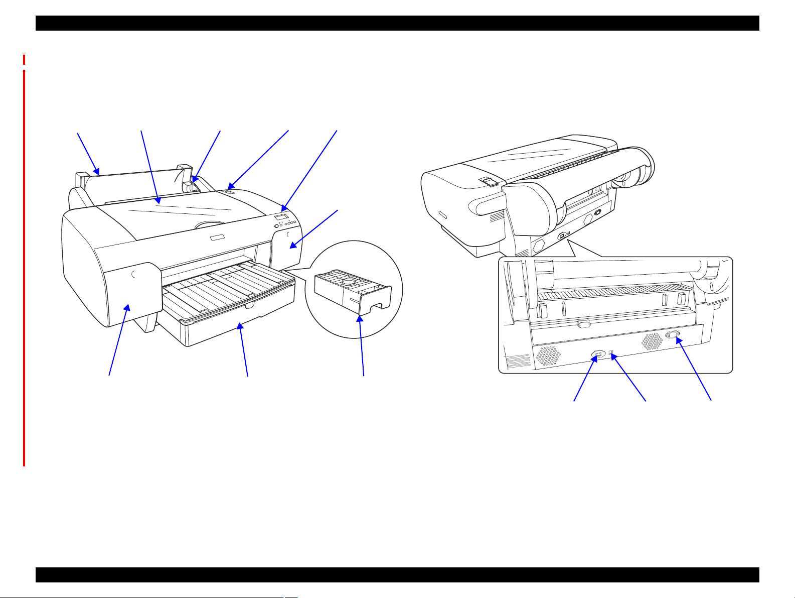
EPSON Stylus Pro 4400/4450/4800/4880/4880C Revision C
Stylus Pro 4450/4880/4880C
Paper Cover
(Left side)
Printer Cover Spindle Paper Set Lever Control Panel
Ink Cartridge Box
(Right side)
ASF Cassette Maintenance TankInk Cartridge Box
Network Interface AC InletUSB Interface
Figure 1-6. External View and Parts Names (Stylus Pro 4450/4880/4880C)
4-color model is equipped with a cover instead of the ink cartridge box (right).
Product Description External View and Parts Names 29
EPSON Stylus Pro 4400/4450/4800/4880/4880C Revision C
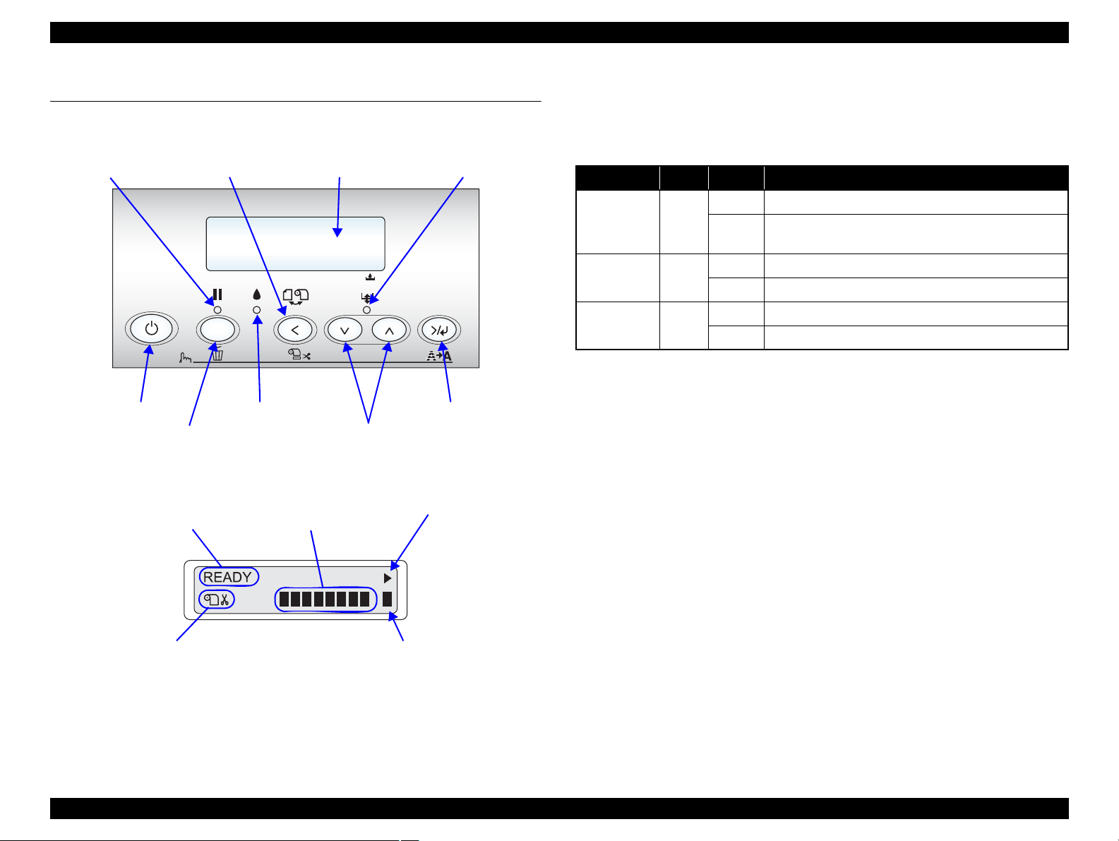
1.4 Operating Panel
1.4.1 Buttons and Functions
Pause LED
Panel Display
(Refer to "1.4.2 Panel
Display (p33)".)
Paper Source / Paper Cut
3sec.
Power
Pause
1 2 3 4 5 6 7 8
Ink check LED
Paper Feed / Eject Paper
Figure 1-7. Panel Design
Remaining Ink Cartridge
(Refer to "1.4.2.4 Ink Remaining
Indicator Display (p38)".)
LCD Paper check LED
Menu
Menu / Cleaning
Shifts to Setting
Item Selection Menu
1.4.1.1 LED
Panel LED types are the following 3 types. The LEDs indicate printer status as
follows.
Table 1-22. LED
LED Color Display Printer Status
On Indicates that the paper is not printable.
Paper check Red
Blink
On Indicates printer pauses operation.
Pause Green
Blink Indicates printer is in operation.
On Indicates error regarding ink occurred.
Ink check Red
Blink Indicates warning status regarding ink.
Indicates error that occurred when feeding / ejecting
paper.
Cut availability for Paper
Type/Roll Paper selection
Available rate of Maintenance Tank
(Refer to "1.4.2.4 Ink Remaining Indicator
Display (p38)".)
Figure 1-8. LCD Panel (8-color model)
Product Description Operating Panel 30
Loading...