


CF5100BS00
Emerson CF5100BS00, CF5100VNB00, CF5100GES00, CF5100VS00, CF5100ORB00 Owner's Manual
...
Part No. F40BP74800000 Form No. BP7480
Revision: 131218 U.L. Model No.: CF5100
READ AND SAVE THESE INSTRUCTIONS
PENBROOKE SELECT
™
Ceiling Fan Owner's Manual
CF5100BS00 - Brushed Steel
CF5100GES00 - Golden Espresso
CF5100ORB00 - Oil Rubbed Bronze
CF5100SW00 - Satin White
CF5100VNB00 - Venetian Bronze
CF5100VS00 - Vintage Steel
Model Numbers
Net Weight: 20.2 Lbs.
Questions, problems, missing parts: Before returning to the store call
Emerson Electric Customer Service
8 a.m. - 6 p.m., Eastern, Monday-Friday
1-800-654-3545
www.emersonfans.com
44”, 54”, or 60” Fan Blades
Not Included
(B79 Not Recommended)
BP7480 CF5100 PENBROOKE SELECT 12/18/13 10:35 AM Page 1
2
Safety Instructions
TO REDUCE THE RISK OF FIRE, ELECTRICAL SHOCK,
OR INJURY TO PERSONS, OBSERVE THE
FOLLOWING:
a. Use this unit only in a manner intended by the
manufacturer. If you have questions, contact the
manufacturer.
b. Before servicing or cleaning unit, switch power off
at service panel and lock service panel
disconnecting means to prevent power from being
switched on accidentally. When the service
disconnecting means cannot be locked, securely
fasten a warning device, such as a tag, to the
service panel.
WARNING
!
Additional Safety Instructions for Installation
1. To avoid possible shock, be sure electricity is turned
off at the fuse box before wiring, and do not operate
fan without blades.
2. All wiring must be in accordance with the National
Electrical Code “ANSI/NFPA 70-2014” and Local
Electrical Codes. Use the National Electrical Code if
Local Codes do not exist. The ceiling fan must be
grounded as a precaution against possible electrical
shock. Electrical installation should be made or
approved by a licensed electrician.
3. The outlet box and joist must be securely mounted
and capable of reliably supporting at least 50 pounds.
Use only U.L. outlet boxes listed as “Acceptable for
Fan Support of 22.7 kg. (50 lbs.) or less”, and use the
mounting screws provided with the outlet box. Most
outlet boxes commonly used for support of light
fixtures are not acceptable for fan support and may
need to be replaced. Consult a qualified electrician if
in doubt.
4. The downrod furnished with the fan provides the
minimum recommended floor to fan blade clearance
for an 8 foot ceiling.
5. The fan must be mounted with the fan blades at least
7 feet from the floor to prevent accidental contact with
the fan blades.
6. Follow the recommended instructions for the proper
method of wiring your ceiling fan. If you do not know
enough about electrical wiring, have your fan installed
by a licensed electrician.
WARNING: To reduce the risk of electrical shock, this
fan must be installed with an isolating wall control/
switch.
NOTE: This fan is suitable for use with solid-state speed
controls.
WARNING: This product is designed to use only those
parts supplied with this product and/or any accessories
designated specifically for use this product by Emerson
Electric Co. Substitution of parts or accessories not
designated for use with this product by Emerson could
result in personal injury or property damage.
WARNING: To reduce the risk of personal injury, do not
bend the blade flange when installing the blade flanges,
balancing the blades or cleaning the fan. Do not insert
foreign objects in between rotating fan blades.
WARNING: To avoid fire, shock or injury, do not use an
Emerson or any other brand of control not specifically
approved for this fan.
NOTE: All setscrews must be checked and re-tightened
where necessary before installation.
1. Read your owner’s manual carefully and keep it for
future reference.
2. Be careful of the fan and blades when cleaning,
painting, or working near the fan. Always turn off the
power to the ceiling fan before servicing.
3. Do not put anything into the fan blades while they are
turning.
4. Do not operate reversing switch until fan blades have
come to a complete stop.
DATE CODE:
The date code of this fan may be found on the box, stamped in ink on a white label. You should record
this data above and keep it in a safe place for future use.
U.L. Model No.: CF5100
READ AND SAVE THESE INSTRUCTIONS
Table of Contents
Section Page
Safety Instructions . . . . . . . . . . . . . . . . . . . . . . . . . . . . . . . .2
1. Unpacking Instructions . . . . . . . . . . . . . . . . . . . . . . . . .3-4
2. Electrical Requirements . . . . . . . . . . . . . . . . . . . . . . . . . .4
3. Ceiling Fan Assembly . . . . . . . . . . . . . . . . . . . . . . . . . .5-8
4. How to Hang Your Ceiling Fan . . . . . . . . . . . . . . . . . .9-10
5. How to Wire Your Ceiling Fan . . . . . . . . . . . . . . . . . . . . .10
6. Final Assembly . . . . . . . . . . . . . . . . . . . . . . . . . . . . . . . .11
7. Switch Cup - Manual Control . . . . . . . . . . . . . . . . . . . . .11
Section Page
8. Maintenance . . . . . . . . . . . . . . . . . . . . . . . . . . . . . . . . . .12
9. Accessories . . . . . . . . . . . . . . . . . . . . . . . . . . . . . . . . . . .12
10. Accent Light Harness Installation . . . . . . . . . . . . . . . . .13
11. Optional AL100 Accent Light Installation . . . . . . . . . . .14
12. Trouble Shooting . . . . . . . . . . . . . . . . . . . . . . . . . . . . . .15
13. Repair Parts . . . . . . . . . . . . . . . . . . . . . . . . . . . . . . .16-17
Ceiling Fan Limited Warranty . . . . . . . . . . . . . . . . . . . . . . .19
BP7480 CF5100 PENBROOKE SELECT 12/18/13 10:35 AM Page 2
1. Unpacking Instructions
3
emersonfans.com
Please contact 1-800-654-3545 for further assistance
U.L. Model No.: CF5100
This product is designed to use only those parts
supplied with this product and/or any accessories
designated specifically for use with this product by
Emerson Electric Co. Substitution of parts or
accessories not designated for use with this product
by Emerson Electric Co. could result in personal injury
or property damage.
WARNING
!
Do not install or use fan if any part is damaged or
missing. Call Toll-Free:
1-800-654-3545
WARNING
!
1.1
Check to see that you have received the following parts:
NOTE: If you are uncertain of part description, refer
to exploded view illustration.
NOTE: Place the parts from the loose parts bags in
a small container to keep them from being lost.
If any parts are missing, contact your local
retailer or catalog outlet for replacement before
proceeding.
1.2
Remove and discard the two cardboard shipping
retainers securing the motor hub in the motor housing
assembly.
1.3
Remove the fan motor assembly from the protective
plastic bag. Place the fan assembly into the upper foam
pad with the bottom of the motor facing up.
The upper foam pad serves as a holder for the fan
during assembly.
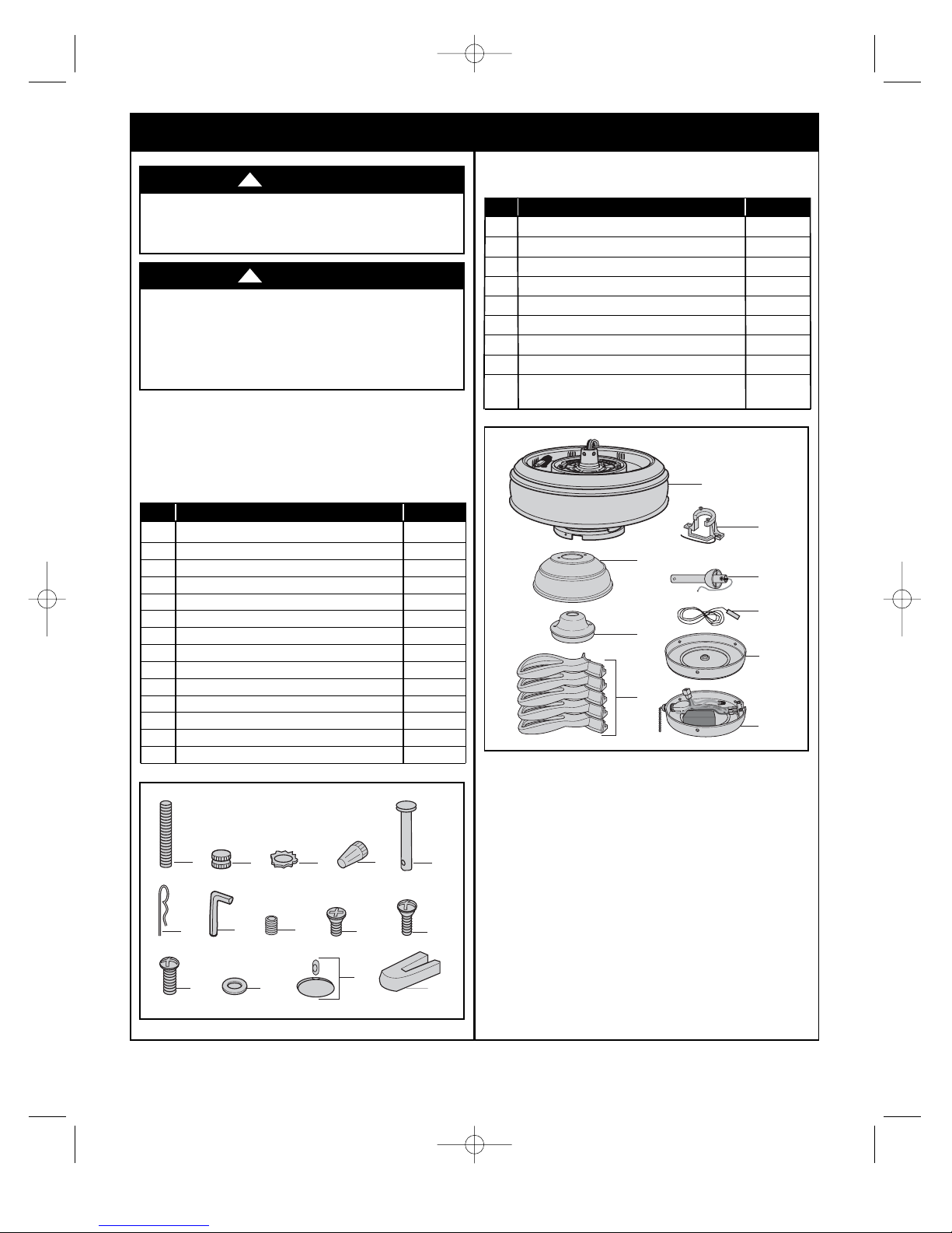
PACKAGE CONTENTS
Part Description Quantity
A Fan Motor & Housing Assembly 1
B Ceiling Cover 1
C Motor Coupler Cover 1
D Blades Flanges 5
E Hanger Bracket 1
F Hanger Ball / Downrod Assembly 1
G Accent Light Harness 1
H Switch Cup 1
I Switch Cup Assembly
(Use w/Manual Switches) 1
HARDWARE CONTENTS
Part Description Quantity
1 Threaded Studs, #8-32 x 1-1/4” 4
2 Knurled Knobs, #8-32 4
3 Lockwashers, External Tooth #8 4
4 Wire Connectors, 12 ga. 5
5 Clevis Pin 1
6 Hairpin Clip 1
7 Setscrew Wrench 1
8 Setscrew 1
9 #6-32 x 3/8” Flat Head Screws 4
10 #10-32 x 5/8” Oval Head Screws 11
11 #10-24 x 12mm Round Head Screws 21
12 Flat Washers 21
13 Pendant & Coupling 1 each
14 Blade Balance Kit 1
BP7480 CF5100 PENBROOKE SELECT 12/18/13 10:35 AM Page 3
1
6
2
7
3
8
4
9
B
C
D
5
10
A
E
F
G
H
I
11
12
13
14
Before assembling your ceiling fan, refer to section on
proper method of wiring your fan (page 10). If you feel
you do not have enough wiring knowledge or
experience, have your fan installed by a licensed
electrician.
WARNING
!
This Manual Is Designed to Make it as Easy as Possible for You to Assemble,
Install, Operate and Maintain Your Ceiling Fan
Tools Needed for Assembly
One Phillips head screwdriver One stepladder
One 1/4” blade screwdriver One wire stripper
Materials
Wiring outlet box and box connectors must be of type
required by the local code. The minimum wire would be
a 3-conductor (2-wire with ground) of following size:
Installed Wire Length Wire Size A.W.G.
Up to 50 ft. 14
50-100 ft. 12
4
U.L. Model No.: CF5100
2. Electrical Requirements
Your new ceiling fan will require a grounded electrical
supply line of 120 volts AC, 60 Hz, 15 amp circuit.
To reduce the risk of fire, electric shock, or personal
injury, mount fan to outlet box marked “Acceptable for
Fan Support of 22.7 kg. (50 lbs.) or less”, and use
screws supplied with outlet box. Most outlet boxes
commonly used for support of light fixtures are not
acceptable for fan support and may need to be
replaced. Consult a qualified electrician if in doubt.
WARNING
!
Turning off wall switch is not sufficient. To avoid
possible electrical shock, be sure electricity is turned
off at the main fuse box before wiring. All wiring must
be in accordance with National and Local codes and
the ceiling fan must be properly grounded as a
precaution against possible electrical shock.
WARNING
!
To avoid fire or shock, follow all wiring instructions
carefully.
Any electrical work not described in these
instructions should be done or approved by a licensed
electrician.
WARNING
!
The outlet box must be securely anchored and capable
of withstanding a load of at least 50 pounds.
If your fan is to replace an existing ceiling light fixture,
turn electricity off at the main fuse box at this time and
remove the existing light fixture.
1. Unpacking Instructions (continued)
BP7480 CF5100 PENBROOKE SELECT 12/18/13 10:35 AM Page 4

3. Ceiling Fan Assembly
5
emersonfans.com
Please contact 1-800-654-3545 for further assistance
U.L. Model No.: CF5100
3.1
Mount the fan blade (sold separately) using the four
#10-24 x 12mm round head screws and flat washers
(supplied) to secure flange to blade (Figure 1).
Repeat for the remaining four blades.
NOTE: Some accessory blades are supplied with
shorter screws. These shorter screws MUST be
used to assemble the blades to flanges.
Figure 1
3.2
Rotate the motor hub to expose the motor flange holes
through the switch cup adapter.
Attach a blade assembly to the motor hub using two
10-32 x 5/8" oval head screws (supplied) (Figure 2).
Do not tighten completely at this time.
Install remaining blade assemblies in the same way.
Gently snug all flange screws to the motor hub, working
around the hub in a clockwise sequence.
The blade flanges have an interlocking feature that must
be fully engaged before tightening the screw. Make sure
all the flanges are properly engaged and then tighten
the flange screws. If one of the flanges does not seat
properly on the motor hub, loosen the adjacent flange
screws, re-engage and reseat the flanges, then tighten
the screws again.
NOTE: Take care not to scratch fan housing
assembly when installing blades.
Figure 2
Installation of Switch Cup for
Accessory Control
3.3
Position the switch cup on the switch cup adapter and
align the holes in the switch cup with the holes in the
adapter. Secure the switch cup adapter by installing the
three #6-32 x 3/8” flat head screws (provided) (Figure
3).
Figure 3
To reduce the risk of personal injury, do not bend the
blade flange when installing the blade flanges,
balancing the blades or cleaning the fan. Do not insert
foreign objects in between rotating fan blades.
WARNING
!
BP7480 CF5100 PENBROOKE SELECT 12/18/13 10:35 AM Page 5
#10-24 x 12mm ROUND
HEAD BLADE SCREW (4)
9/16" FLAT
WASHER
(4 per blade/flange)
FAN BLADE
(sold separately)
#10-32 x 5/8" OVAL
HEAD SCREWS (2 per
flange/blade assembly)
SWITCH CUP
ADAPTER HOLE
BLADE FLANGE
ASSEMBLY
SWITCH CUP
BLADE
FLANGE
#6-32 x 3/8" FLAT
HEAD SCREWS (3)
6
U.L. Model No.: CF5100
3. Ceiling Fan Assembly (continued)
Installation of Switch Cup
Assembly for Manual Control
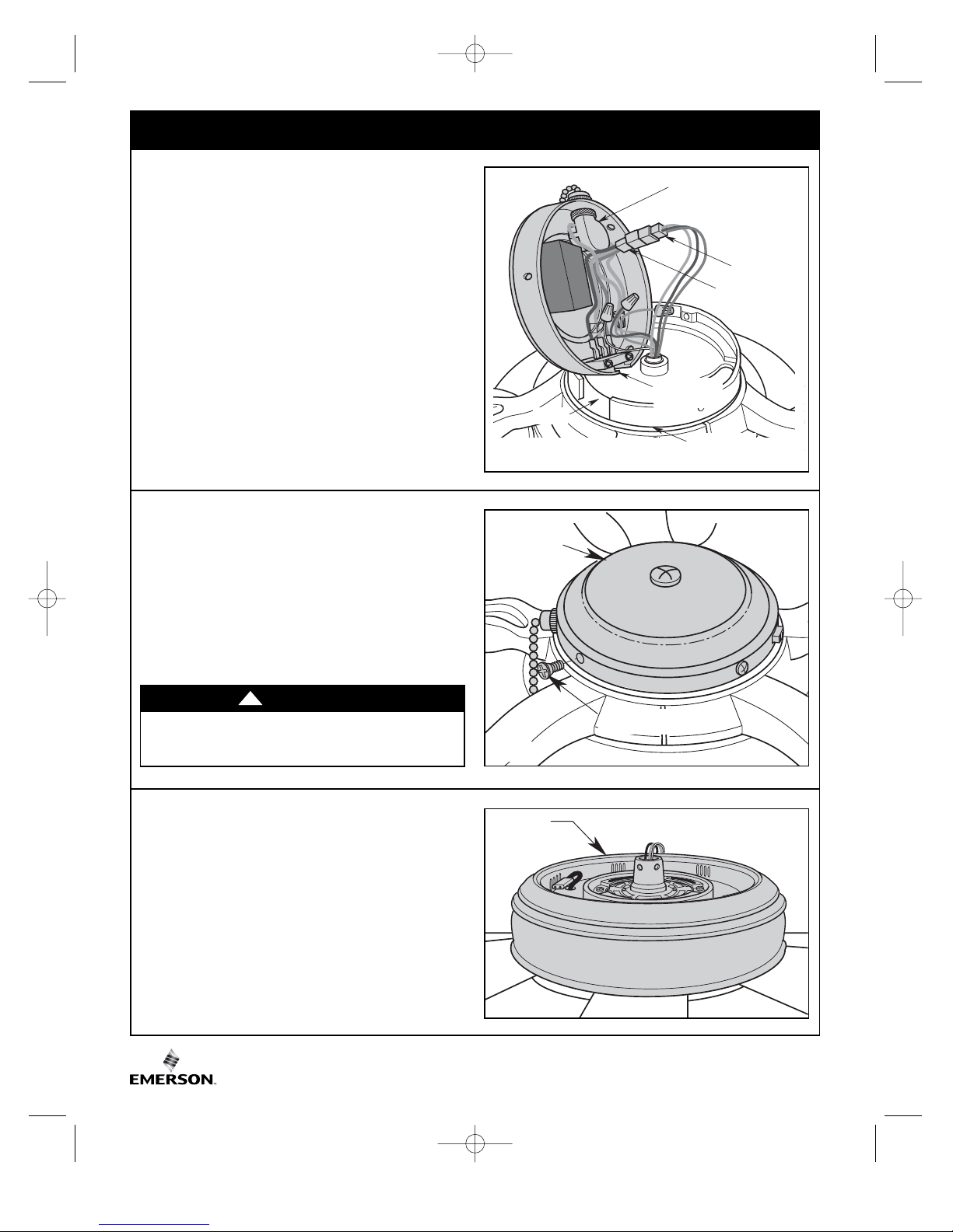
3.4
Engage the connector of the switch cup assembly with
the motor connector (Figure 4). The two connectors are
keyed and color-coded and must be mated correctly
(color-to-color) before they can be engaged. Make sure
the connector latch closes properly.
Rotate the switch cup assembly to align the pull chain
switch with the slot of the switch cup adapter (Figure 4).
Figure 4
Installation of Switch Cup
Assembly for Manual Control
3.5
Carefully tuck all wires and connectors under the switch
cup assembly.
Secure the switch cup assembly by installing the three
#6-32 x 3/8” flat head screws (provided) (Figure 5).
Figure 5
3.6
Turn the partially assembled ceiling fan right side up for
final preparation. Place the fan carefully onto the top of
the styrofoam as not to bend the ceiling fan blades
(Figure 6).
Figure 6
To avoid possible fire or shock, do not pinch wires
between the switch cup assembly and the switch cup
adapter.
WARNING
!
BP7480 CF5100 PENBROOKE SELECT 12/18/13 10:35 AM Page 6
PULL CHAIN SWITCH
SLOT
SWITCH CUP
ASSEMBLY
SWITCH CUP
ASSEMBLY
#6-32 x 3/8" FLAT
HEAD SCREWS (3)
MOTOR
CONNECTOR
SWITCH CUP
ASSEMBLY
CONNECTOR
SWITCH CUP
ADAPTER
PARTIALLY
ASSEMBLED
CEILING FAN
 Loading...