


 Loading...
Quick Start Guide
00825-0200-4420, Rev FE
August 2015
Emerson™ Smart Wireless Gateway 1420

Quick Start Guide |
August 2015 |
|
|
NOTICE
This guide provides basic guidelines for the Smart Wireless Gateway. It does not provide instructions for diagnostics, maintenance, service, or troubleshooting. Refer to the Smart Wireless Gateway Reference Manual (document number 00809-0200-4420) for more information and instructions. This guide and the manual are available electronically on www.emersonprocess.com.
Explosions could result in death or serious injury.
Installation of this device in an explosive environment must be in accordance with the appropriate local, national, and international standards, codes, and practices. Review the Product Certifications section for any restrictions associated with a safe installation.
Avoid contact with the leads and terminals. High voltage may be present on leads can cause electrical shock.
This device complies with Part 15 of the FCC Rules. Operation is subject to the following conditions:
This device may not cause harmful interference.
This device must accept any interference received, including interference that may cause undesired operation.
This device must be installed to ensure a minimum antenna separation distance of 20 cm from all persons.
Contents
Wireless considerations . . . . . . . . . . . . . . . . 3 Software installation (optional) . . . . . . . .17 General considerations . . . . . . . . . . . . . . . . . 4 Verify operations . . . . . . . . . . . . . . . . . . . . . .18 Initial connection and configuration . . . . 5 Product specifications . . . . . . . . . . . . . . . . .19 Physical installation . . . . . . . . . . . . . . . . . . .11 Product Certifications . . . . . . . . . . . . . . . . .22 Connect to the host system . . . . . . . . . . .16
2
August 2015 |
Quick Start Guide |
|
|
Wireless considerations
Power up sequence
The Smart Wireless Gateway (Gateway) should be installed and functioning properly before power modules are installed in any wireless field devices. Wireless field devices should also be powered up in order of proximity from the Smart Wireless Gateway beginning with the closest. This will result in a simpler and faster network installation.
Antenna position
The antenna should be positioned vertically, and be approximately 3-ft. (1 m) from large structures or buildings to allow for clear communication to other devices.
Mounting height
For optimal wireless coverage, the Gateway or remote antenna is ideally mounted 15to 25-ft. (4,6 to 7,6 m) above ground or 6-ft. (2 m) above obstructions or major infrastructure.
Gateway redundancy
If the wireless Gateway was ordered with redundancy (Gateway Redundancy code RD), refer to Appendix D in the Smart Wireless Gateway Reference Manual (document number 00809-0200-4420) for additional installation instructions.
3
Quick Start Guide |
August 2015 |
|
|
General considerations
PC requirements
Operating system (optional software only)
Microsoft® Windows™ XP Professional, Service Pack 3
Windows Server 2003 Service Pack 2
Windows Server 2003 R2 Service Pack 2
Windows Server 2008 (Standard Edition), Service Pack 2
Windows Server 2008 R2 Standard Edition, Service Pack 1
Windows 7 Professional, Service Pack 1
Windows 7 Enterprise, Service Pack 1
Applications
Internet Explorer® 6.0 or higher
Mozilla Firefox® 1.5 or higher
.Net Framework 2.0 (for OPC proxy only) Hard disk space
AMS® Wireless Configurator: 1.5 GB
Gateway Setup CD: 250 MB
4
August 2015 |
Quick Start Guide |
|
|
Step 1: Initial connection and configuration
DeltaV™ ready
If the Gateway was ordered DeltaV Ready (Data Protocols Code 5), then skip to Step 2: Physical installation, and connect the Gateway to a DeltaV 10.3 or newer control network.
Initial connection and configuration
To configure the Smart Wireless Gateway, a local connection between a PC/laptop and the Gateway needs to be established.
Powering the Gateway
Bench top power will be needed to power the Gateway by wiring a 24 VDC (nominal) power source, with at least 250 mA, to the power terminals.
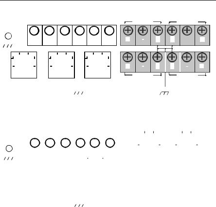
Figure 1. Legacy Gateway Terminal Block Diagram
|
|
|
|
24 VDC |
|
|
|
|
|
|
|
|
|
|
|
|
|
|
|
|
|
|
|
|
|
||||
|
|
|
|
(nominal) |
|
|
|
|
|
|
|
|
|
|
|
|
|
Serial ® |
|
|
|
||||||||
|
|
|
Power Input |
|
|
|
|
|
|
|
|
|
|
|
|
|
Modbus |
|
|
|
Not Used |
Not Used |
|||||||
|
|
|
|
|
|||||||||||||||||||||||||
|
|
|
|
|
|
|
|
|
|
|
|
|
|
|
|
|
|
|
|
|
|
|
|
|
|
|
|
|
|
|
|
|
|
|
|
|
|
|
|
|
|
|
|
|
|
|
|
|
|
|
|
|
|
|
|
|
|
|
|
|
|
|
|
|
|
|
|
|
|
|
|
|
|
|
|
|
|
|
|
|
|
|
|
|
|
|
|
|
|
|
|
|
+ |
|
- |
|
|
|
S |
|
|
|
|
|
A |
B |
|
|
|
|
|
|
|
|
|
|
|
|
|
|
|
|
|
|
|
|
|
|
|
|
|
|
|
|
- |
|
|
|
|
|
|
|
|
|
|
||||||||||||||||||||||
|
|
|
|
+ |
|
|
|
|
|
|
|
|
|
|
|
|
S |
S |
|
|
|
|
|
|
|
|
|
|
|
|
|
|
|||||||||||||||||||||||||||||||||||||||||||||
|
|
|
|
|
+ |
|
|||||||||||||||||||||||||||||||||||||||||||||||||||||||||||||||||||||||
Case |
|
|
|
|
|
|
|
|
|
|
|
|
|
|
|
|
|
|
|
|
|
|
|
|
|
|
|
|
|
|
|
|
|
|
|
|
|
|
|
|
|
|
|
|
|
|
|
|
|
|
|
|
|
|
|
|
|
|
|
|
|
|
|
|
|
|
|
||||||||||
|
|
|
|
|
|
|
|
|
|
|
|
|
|
|
|
|
|
|
|
|
|
|
|
|
|
|
|
|
|
|
|
|
|
|
|
|
|
|
|
|
|
|
|
|
|
|
|
|
|
|
|
|
|
|
|
|
|
|
|
|
|
|
|
|
|
|
|||||||||||
|
|
|
|
|
|
|
|
|
|
|
|
|
|
|
|
|
|
|
|
|
|
|
|
|
|
|
|
|
|
|
|
|
|
|
|
|
|
|
|
|
|
|
|
|
|
|
|
|
|
|
|
|
|
|
|
|
|
|
|
|
|
|
|
|
|
|
|||||||||||
|
|
|
|
|
|
|
|
|
|
|
|
|
|
|
|
|
|
|
|
|
|
|
|
|
|
|
|
|
|
|
|
|
|
|
|
|
|
|
|
|
|
|
|
|
|
|
|
|
|
|
|
|
|
|
|
|
|
|
|
|
|
|
|
|
|
|
|
|
|
|
|
|
|
|
|
|
|
|
|
|
|
|
|
|
|
|
|
|
|
|
|
|
|
|
|
|
|
|
|
|
|
|
|
|
|
|
|
|
|
|
|
|
|
|
|
|
|
|
|
|
|
|
|
|
|
|
|
|
|
|
|
|
|
|
|
|
|
|
|
|
|
|
|
|
|
|
|
|
|
|
|
|
|
||
|
|
|
|
|
|
|
|
|
|
|
|
|
|
|
|
|
|
|
|
|
|
|
|
|
|
|
|
|
|
|
|
|
|
|
|
|
|
|
|
|
|
|
|
|
|
|
|
|
|
|
|
|
|
|
|
|
|
|
|
|
|
|
|
|
|
|
|
|
|
|
|
|
|
|
|
|
|
|
|
|
|
|
|
|
|
|
|
|
|
|
|
|
|
|
|
|
|
|
|
|
|
|
|
|
|
|
|
|
|
|
|
|
|
|
|
|
|
|
|
|
|
|
|
|
|
|
|
|
|
|
|
|
|
|
|
|
|
|
|
|
|
|
|
|
|
|
|
|
|
|
|
|
|
|
|
|
|
|
|
|
|
|
|
|
|
|
|
|
|
|
|
|
|
|
|
|
|
|
|
|
|
|
|
|
|
|
|
|
|
|
|
|
|
|
|
+ |
|
|
|
|
|
|
|
|
|
|
|
|
S |
|
|
|
|
S |
|
|
|
|
|
|
|
|
|
|
|
|
|
+ |
|
|
|||
|
|
|
|
Ethernet 2 |
|
|
|
|
|
|
Ethernet 2 |
|
|
|
|
Ethernet 1 |
|
|
|
Not Used |
|
|
|
|
|
Not Used |
|
|
|
||||||||||||||||||||||||||||||||||||||||||||||||
|
|
|
|
with Power |
|
|
|
|
|
|
|
|
|
|
|
|
|
|
|
|
|
|
|||||||||||||||||||||||||||||||||||||||||||||||||||||||
|
|
|
|
(Covered) |
|
|
(Secondary) |
|
|
|
|
|
(Primary) |
|
|
|
|
|
|
|
|
|
|
|
|
|
|
|
|
|
|
|
|
|
|
|
|
|
|
|
|
|
|
|
|
|
|
|
|
|
|
|
|
|
|
|
|
|
|||||||||||||||||||
|
|
|
|
|
|
|
|
|
|
|
|
|
|
|
|
|
|
|
|
|
|
|
|
|
|
|
|
|
|
|
|
|
|
|
|
|
|
|
|
|
|
|
|
|
|
|
|
|
|
|
|
|
|
|
|
|
|
|
|
|
|
|
|
|
|
|
|
|
|
|
|
|
|
|
|
|
|
|
|
|
|
|
|
|
|
|
|
|
|
|
|
|
|
|
|
|
|
|
|
|
|
|
|
|
|
|
|
|
|
|
|
|
|
|
|
|
|
|
|
|
|
|
|
|
|
|
|
|
|
|
|
|
|
|
|
|
|
|
|
|
|
|
|
|
|
|
|
|
|
|
|
|
|
|
|
|
|
|
|
|
|
|
|
|
|
|
|
|
|
|
|
|
|
|
|
|
|
|
|
|
|
|
|
|
|
|
|
|
|
|
|
|
|
|
|
|
|
|
|
|
|
|
|
|
|
|
|
|
|
|
|
|
|
|
|
|
|
|
|
|
|
|
|
|
|
|
|
|
|
|
|
|
|
|
|
|
|
|
|
|
|
|
|
|
|
|
|
|
|
|
|
|
|
|
|
|
|
|
|
|
|
|
|
|
|
|
|
|
|
|
|
|
|
|
|
|
|
|
|
|
|
|
|
|
|
|
|
|
|
|
|
|
|
|
|
|
|
|
|
|
|
|
|
|
|
|
|
|
|
|
|
Figure 2. Power over Ethernet (PoE) Terminal Block Diagram |
|
|
|
|
|
|
|
|
|
|
|
|
|
|
|
|
|
|
|
||||||||||||||||||||||||||||||||||||||||||||||||||||||||||
|
|
|
|
|
|
|
|
|
24 VDC |
|
|
|
|
|
|
|
|
|
|
|
|
|
|
|
|
|
|
|
|
|
|
|
|
|
|
|
|
|
|
|
|
|
|
|
|
|
|
|
|
|
|
|
|
|
|
|
|
|
|
|
|
|
|
|
|
|
|
|
|
|
|
|
|
||||
|
|
|
|
|
|
|
|
(nominal) |
|
|
|
|
|
|
|
|
|
|
|
|
|
|
|
|
Serial |
|
|
|
|
|
|
|
|
|
|
|
|
|
|
|
|
|
|
|
|
|
|
|
|
|
|
|
|
|
|
|
|
|
|
|
|
|
|
|
|||||||||||||
|
|
|
|
|
|
|
Power Input |
|
|
|
|
|
|
|
|
|
|
Modbus |
|
|
|
|
|
|
|
|
|
|
|
|
|
|
|
|
|
|
|
|
|
|
|
|
|
|
|
|
|
|
|
|
|
|
|
|
|
|
|
|
|
||||||||||||||||||
|
|
|
|
|
|
+ |
|
- |
|
|
|
S |
|
|
|
|
|
|
|
|
A |
|
B |
|
|
|
|
|
|
|
|
|
|
|
|
|
|
|
|
|
|
|
|
|
|
|
|
|
|
|
|
|
|
|
|
|
|
||||||||||||||||||||
|
|
|
|
|
|
|
|
|
|
|
|
|
|
|
|
|
|
|
|
|
|
|
|
|
Ethernet 2 |
|
|
|
|
|
|
Ethernet 1 |
|
|
|
||||||||||||||||||||||||||||||||||||||||||
|
|
|
|
|
|
|
|
|
|
|
|
|
|
|
|
|
|
|
|
|
|
|
|
|
|
|
|
|
|
|
|
|
|||||||||||||||||||||||||||||||||||||||||||||
|
|
|
|
|
|
|
|
|
|
|
|
|
|
|
|
|
|
|
|
|
|
|
|
|
|
|
|
|
|
|
|
|
|
|
|
|
|
|
|
|
|
|
|
(Secondary) |
|
|
|
|
|
(Primary) |
|
|
|
||||||||||||||||||||||||
Case |
|
|
|
|
|
|
|
|
|
|
|
|
|
|
|
|
|
|
|
|
|
|
|
|
|
|
|
|
|
|
|
|
|
|
|
|
|
|
|
|
|
|
|
|
|
|
|
|
|
|
|
|
|
|
|
|
|
|
|
|
|
|
|
|
|
|
|
||||||||||
|
|
|
|
|
|
|
|
|
|
|
|
|
|
|
|
|
|
|
|
|
|
|
|
|
|
|
|
|
|
|
|
|
|
|
|
|
|
|
|
|
|
|
|
|
|
|
|
|
|
|
|
|
|
|
|
|
|
|
|
|
|
|
|
|
|
|
|
|
|
|
|
|
|
|
|
|
|
|
|
|
|
|
|
|
|
|
|
|
|
|
|
|
|
|
|
|
|
|
|
|
|
|
|
|
|
|
|
|
|
|
|
|
|
|
|
|
|
|
|
|
|
|
|
|
|
|
|
|
|
|
|
|
|
|
|
|
|
|
|
|
|
|
|
|
|
|
|
|
|
|
|
|
|
|
|
5

Quick Start Guide |
August 2015 |
|
|
Note
Figure 1 depicts the terminal block of legacy Gateways prior to the introduction of PoE capabilities. Figure 2 shows the terminal block arrangement of a PoE version of the Gateway. If the Gateway will be powered via the standard 24 volt power input terminals, and no PSE is desired, it is not necessary to change the default settings of the PoE jumper matrix.
Note
The Gateway enclosure case should always grounded in accordance with national and local electrical codes. The most effective grounding method is a direct connection to earth ground with minimal impedance.
Figure 3. 1420 PoE Jumpering Matrix (Located on 1420 Board)
Black fill below indicates jumper.
PoE PD on port 1
(Default jumpering for production. Used for no PoE also)
PoE PD on port 2
PoE PSE on port 1
PoE PSE on port 2
Legend:
ETH1: Ethernet port 1 selected for PD or PSE ETH2: Ethernet port 2 selected for PD or PSE
PD: Gateway derived its power off the Ethernet port selected
PSE: The Gateway is powered via the standard 24 volt power input terminals and provides power via the selected Ethernet port to another device with a compatible PD port.
EN: Enabled; this enables the PSE operation DIS: Disabled; this disables the PSE operation
Note
Electrostatic discharge (ESD) protection required when swapping PoE jumpers.
6
August 2015 |
Quick Start Guide |
|
|
Note
Only one port and one mode of operation (PD or PSE) can be selected at a time; any other combination of jumpers is invalid.
Note
IEEE 802.3af-2003 PoE standard provides up to 15.4 W of DC power (minimum 44 V DC and 350 mA) to each device. Only 12.95 W is assured to be available at the powered device as some power is dissipated in the cable.
IEEE 802.3at-2009 PoE standard also known as “PoE+” or “PoE plus”, provides up to 25.5 W of power. The 2009 standard prohibits a powered device from using all four pairs for power.
For more information on PoE and frequently asked questions, reference document number 00870-0500-4420.
Establishing a connection
Note
For information on connecting a Windows 7 PC, see Technical Note (document number 00840-0900-4420).
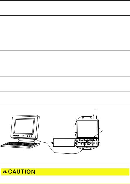
1. Connect the PC/laptop to the Ethernet 1 (Primary) receptacle on the Gateway.
Figure 4. Gateway PC/Laptop Connection
A
B
24 V DC |
|
Power Input |
Modbus |
+ |
- |
S |
S |
A |
B |
Case
POE |
P2 |
P1 |
Not Used |
Not Used |
+ |
- |
S |
S |
- |
+ |
+ |
- |
S |
S |
- |
+ |
Not Used |
Not Used |
A.PC/laptop
B.Ethernet 1 receptacle
Do not connect to the Ethernet 2 with power (covered) port. This port supplies power and could damage the PC/laptop.
2.To establish the PC/laptop settings, navigate to Start>Settings>Network Connections.
a.Select Local Area Connection.
b.Right click to select Properties.
7
Quick Start Guide |
August 2015 |
|
|
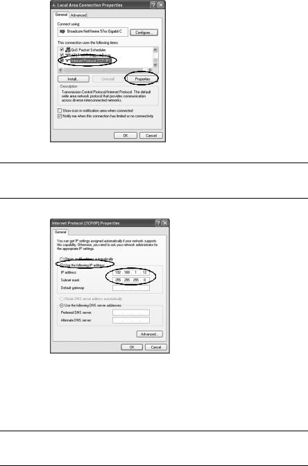
c.Select Internet Protocol (TCP/IP), then select the Properties button.
Note
If the PC/laptop is from another network, record the current IP address and other settings so the PC/laptop can be returned to the original network after the Gateway has been configured.
d.Select the Use the following IP address button.
e.In the IP address field, enter 192.168.1.12.
f.In the Subnet mask field, enter 255.255.255.0.
g.In the Internet Protocol (TCP/IP) Properties window, select OK.
h.In the Local Area Connection Properties window, select OK.
Note
Connecting to the Gateway's secondary Ethernet port requires different network settings. Refer to Table 1 for additional network settings.
8
August 2015 Quick Start Guide
Table 1. Default IP Addresses
|
Gateway |
PC/laptop |
|
|
|
Ethernet 1 |
192.168.1.10 |
192.168.1.12 |
Ethernet 2 |
192.168.2.10 |
192.168.2.12 |
Ethernet 1 (DeltaV Ready) |
10.5.255.254 |
10.5.255.200 |
Ethernet 2 (DeltaV Ready) |
10.9.255.254 |
10.9.255.200 |
|
|
|
Table 2. Subnet Settings
Subnet mask
Default |
255.255.255.0 |
|
|
DeltaV |
255.254.0.0 |
|
|
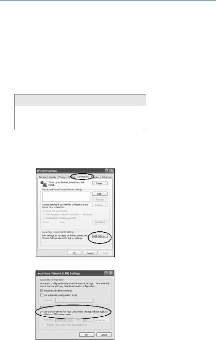
3.Disable proxies.
a.Open a standard web browser (Internet Explorer, Mozilla Firefox, or other).
b.Navigate to Tools>Internet Options>Connections>LAN Settings.
c.Uncheck the box under Proxy Server.
9
Loading...